DE102011055754A1 - Solar cell module and method for interconnecting solar cells - Google Patents
Solar cell module and method for interconnecting solar cellsDownload PDFInfo
- Publication number
- DE102011055754A1 DE102011055754A1DE102011055754ADE102011055754ADE102011055754A1DE 102011055754 A1DE102011055754 A1DE 102011055754A1DE 102011055754 ADE102011055754 ADE 102011055754ADE 102011055754 ADE102011055754 ADE 102011055754ADE 102011055754 A1DE102011055754 A1DE 102011055754A1
- Authority
- DE
- Germany
- Prior art keywords
- solar cells
- carrier
- connectors
- solar cell
- solar
- Prior art date
- Legal status (The legal status is an assumption and is not a legal conclusion. Google has not performed a legal analysis and makes no representation as to the accuracy of the status listed.)
- Granted
Links
Images


Classifications
- H—ELECTRICITY
- H02—GENERATION; CONVERSION OR DISTRIBUTION OF ELECTRIC POWER
- H02S—GENERATION OF ELECTRIC POWER BY CONVERSION OF INFRARED RADIATION, VISIBLE LIGHT OR ULTRAVIOLET LIGHT, e.g. USING PHOTOVOLTAIC [PV] MODULES
- H02S40/00—Components or accessories in combination with PV modules, not provided for in groups H02S10/00 - H02S30/00
- H02S40/30—Electrical components
- H02S40/34—Electrical components comprising specially adapted electrical connection means to be structurally associated with the PV module, e.g. junction boxes
- H02S40/345—Electrical components comprising specially adapted electrical connection means to be structurally associated with the PV module, e.g. junction boxes with cooling means associated with the electrical connection means, e.g. cooling means associated with or applied to the junction box
- H—ELECTRICITY
- H10—SEMICONDUCTOR DEVICES; ELECTRIC SOLID-STATE DEVICES NOT OTHERWISE PROVIDED FOR
- H10F—INORGANIC SEMICONDUCTOR DEVICES SENSITIVE TO INFRARED RADIATION, LIGHT, ELECTROMAGNETIC RADIATION OF SHORTER WAVELENGTH OR CORPUSCULAR RADIATION
- H10F19/00—Integrated devices, or assemblies of multiple devices, comprising at least one photovoltaic cell covered by group H10F10/00, e.g. photovoltaic modules
- H10F19/90—Structures for connecting between photovoltaic cells, e.g. interconnections or insulating spacers
- H10F19/902—Structures for connecting between photovoltaic cells, e.g. interconnections or insulating spacers for series or parallel connection of photovoltaic cells
- H10F19/908—Structures for connecting between photovoltaic cells, e.g. interconnections or insulating spacers for series or parallel connection of photovoltaic cells for back-contact photovoltaic cells
- H—ELECTRICITY
- H10—SEMICONDUCTOR DEVICES; ELECTRIC SOLID-STATE DEVICES NOT OTHERWISE PROVIDED FOR
- H10F—INORGANIC SEMICONDUCTOR DEVICES SENSITIVE TO INFRARED RADIATION, LIGHT, ELECTROMAGNETIC RADIATION OF SHORTER WAVELENGTH OR CORPUSCULAR RADIATION
- H10F71/00—Manufacture or treatment of devices covered by this subclass
- H10F71/121—The active layers comprising only Group IV materials
- H—ELECTRICITY
- H10—SEMICONDUCTOR DEVICES; ELECTRIC SOLID-STATE DEVICES NOT OTHERWISE PROVIDED FOR
- H10F—INORGANIC SEMICONDUCTOR DEVICES SENSITIVE TO INFRARED RADIATION, LIGHT, ELECTROMAGNETIC RADIATION OF SHORTER WAVELENGTH OR CORPUSCULAR RADIATION
- H10F77/00—Constructional details of devices covered by this subclass
- H10F77/20—Electrodes
- H10F77/206—Electrodes for devices having potential barriers
- H10F77/211—Electrodes for devices having potential barriers for photovoltaic cells
- H10F77/219—Arrangements for electrodes of back-contact photovoltaic cells
- H—ELECTRICITY
- H10—SEMICONDUCTOR DEVICES; ELECTRIC SOLID-STATE DEVICES NOT OTHERWISE PROVIDED FOR
- H10F—INORGANIC SEMICONDUCTOR DEVICES SENSITIVE TO INFRARED RADIATION, LIGHT, ELECTROMAGNETIC RADIATION OF SHORTER WAVELENGTH OR CORPUSCULAR RADIATION
- H10F77/00—Constructional details of devices covered by this subclass
- H10F77/93—Interconnections
- H10F77/933—Interconnections for devices having potential barriers
- H10F77/935—Interconnections for devices having potential barriers for photovoltaic devices or modules
- H10F77/937—Busbar structures for modules
- Y—GENERAL TAGGING OF NEW TECHNOLOGICAL DEVELOPMENTS; GENERAL TAGGING OF CROSS-SECTIONAL TECHNOLOGIES SPANNING OVER SEVERAL SECTIONS OF THE IPC; TECHNICAL SUBJECTS COVERED BY FORMER USPC CROSS-REFERENCE ART COLLECTIONS [XRACs] AND DIGESTS
- Y02—TECHNOLOGIES OR APPLICATIONS FOR MITIGATION OR ADAPTATION AGAINST CLIMATE CHANGE
- Y02E—REDUCTION OF GREENHOUSE GAS [GHG] EMISSIONS, RELATED TO ENERGY GENERATION, TRANSMISSION OR DISTRIBUTION
- Y02E10/00—Energy generation through renewable energy sources
- Y02E10/50—Photovoltaic [PV] energy
- Y02E10/547—Monocrystalline silicon PV cells
- Y—GENERAL TAGGING OF NEW TECHNOLOGICAL DEVELOPMENTS; GENERAL TAGGING OF CROSS-SECTIONAL TECHNOLOGIES SPANNING OVER SEVERAL SECTIONS OF THE IPC; TECHNICAL SUBJECTS COVERED BY FORMER USPC CROSS-REFERENCE ART COLLECTIONS [XRACs] AND DIGESTS
- Y02—TECHNOLOGIES OR APPLICATIONS FOR MITIGATION OR ADAPTATION AGAINST CLIMATE CHANGE
- Y02P—CLIMATE CHANGE MITIGATION TECHNOLOGIES IN THE PRODUCTION OR PROCESSING OF GOODS
- Y02P70/00—Climate change mitigation technologies in the production process for final industrial or consumer products
- Y02P70/50—Manufacturing or production processes characterised by the final manufactured product
Landscapes
- Photovoltaic Devices (AREA)
Abstract
Translated fromGermanDescription
Translated fromGermanDie Erfindung bezieht sich auf ein Solarzellenmodul umfassend auf einem Träger angeordnete Solarzellen, die mittels Verbinder verschaltet sind. Auch nimmt die Erfindung Bezug auf ein Verfahren zum Verschalten von erste und zweite Kontakte aufweisenden Solarzellen zu einem Modul, wobei die Solarzellen mit den Rückseiten auf einem Träger angeordnet werden, der erste und zweite elektrische Verbinder aufweist, über die die Solarzellen mit ihren ersten und zweiten Kontakten in Verschaltungspunkten verschaltet werden.The invention relates to a solar cell module comprising solar cells arranged on a support, which are interconnected by means of connectors. Also, the invention relates to a method of interconnecting first and second contact solar cells to a module, wherein the solar cells are disposed with the back sides on a support having first and second electrical connectors over which the solar cells with their first and second Contacts in interconnection points are interconnected.
Um geeignete Spannungen bzw. Leistungen mit Solarzellen bereitzustellen, ist es bekannt, diese zu größeren Einheiten zu verschalten. Zur Herstellung entsprechender Module werden die Zellen parallel oder in Serie miteinander verschaltet und in einem geeigneten transparenten Verkapselungsmaterial wie Ethylenvinylacetet (EVA) eingebettet. Frontseitig werden entsprechende Module üblicherweise von einer Glasscheibe und rückseitig von einer witterungsfesten Kunststoffverbundfolie wie Polyvinylfluorid (TEDLAR) und Polyester abgedeckt. Das Modul selbst ist von einem Rahmen z. B. aus Aluminium umgeben.In order to provide suitable voltages or power with solar cells, it is known to interconnect them to larger units. To produce appropriate modules, the cells are connected in parallel or in series and embedded in a suitable transparent encapsulating material such as ethylene vinyl acetate (EVA). On the front side, corresponding modules are usually covered by a glass pane and on the back by a weather-resistant plastic composite film such as polyvinyl fluoride (TEDLAR) and polyester. The module itself is of a frame z. B. surrounded aluminum.
Typische Solarzellenmodule auf Silicium-Waferbasis weisen Kontakte auf der Vorder- und Rückseite auf. Zur Verschaltung der Solarzellen wird der Frontkontakt einer Solarzelle mit dem Rückkontakt der folgenden verbunden. Somit ist eine Verschaltung zu Strings möglich. Dabei müssen die Verbinder zwischen den Zellen eine hinreichende Länge aufweisen, um wärmebedingte Relativbewegungen zuzulassen. Dies wiederum führt dazu, dass die Solarzellen in gewissen Abständen zueinander angeordnet werden, so dass nicht aktive Modulflächen entstehen. Hierdurch bedingt und durch die Abschattung der frontseitig verlaufenden Kontakte wie Kontaktfinger und Busbars, die mit den Verbindern elektrisch leitend verbunden werden, treten Leistungseinbußen auf.Typical silicon wafer-based solar cell modules have contacts on the front and back. For interconnecting the solar cells, the front contact of a solar cell is connected to the back contact of the following. Thus, an interconnection to strings is possible. In this case, the connectors between the cells must have a sufficient length to allow heat-related relative movements. This in turn means that the solar cells are arranged at certain distances from each other, so that non-active module surfaces arise. As a result, and due to the shading of the front side extending contacts such as contact fingers and busbars, which are electrically connected to the connectors, performance losses occur.
Bei Frontseitenkontaktsolarzellen wird üblicherweise ein auf der dem Licht zugewandten Seite aufgebrachtes elektrisch leitendes Grid bestehend aus Stromsammlern (Grid-Fingern) und Stromableitern (Busbars) mit dem zumeist durch eine zusammenhängende Metallschicht wie Aluminium oder eine rückseitig passivierende Silicium-Nitridschicht mit Aussparungen für die Aluminium-Kontaktierung als Rückseitenkontakt verbunden. Auch werden sogenannte Bifacial-Zellen mit lichtdurchlässigen Rückseitenkontakten zu Frontkontaktsolarzellen gezählt.In the case of front-side contact solar cells, an electrically conductive grid applied on the side facing the light is usually composed of current collectors (grid fingers) and current conductors (busbars), usually by a continuous metal layer such as aluminum or a backside passivating silicon nitride layer with recesses for the aluminum Contacting connected as back contact. Also, so-called bifacial cells are counted with translucent backside contacts to front contact solar cells.
Die Serienverschaltung der entsprechenden Solarzellen erfolgt üblicherweise dadurch, dass die Solarzellen einzeln mit als Zellverbinder zu bezeichnenden Kontaktbändern aus z. B. verzinntem Kupfer verlötet werden, anschließend zu einem sogenannten String zusammengefasst und in Reihe geschaltet werden. Die Strings werden palettenweise angeordnet und über weitere verzinnte Kupferbänder in Reihe verschaltet.The series connection of the corresponding solar cells is usually carried out in that the solar cells individually with as cell connector to be designated contact bands of z. B. tin-plated copper are soldered, then combined into a so-called string and connected in series. The strings are arranged in pallets and connected in series via other tinned copper strips.
Um höhere Wirkungsgrade und damit Leistungen zu erzielen, können Rückseitenkontaktsolarzellen verwendet werden, deren beiden Kontakte auf der Zellenrückseite, d. h. der strahlabgewandten Seite angeordnet sind. Hierdurch wird eine unerwünschte Abschattung wegen des Wegfalls der Busbars und je nach Solarzellentyp eventuell auch der Kontaktfinger auf der Frontseite vermieden. Ferner kann die Packungsdichte der Solarzellen vom Modul erhöht werden, da co-planare Verbinder verwendet werden können.In order to achieve higher efficiencies and thus achievements, back contact solar cells can be used, the two contacts on the back of the cell, d. H. the jet side facing away are arranged. As a result, unwanted shading is avoided because of the omission of the busbars and depending on the type of solar cell, possibly also the contact fingers on the front. Furthermore, the packing density of the solar cells can be increased from the module, since co-planar connectors can be used.
Bei entsprechenden Rückseitenkontaktsolarzellen unterscheidet man üblicherweise zwischen Metal Wrap Through(MWT)-Solarzellen und Emitter Wrap Through(EWT)-Solarzellen. Bei MWT-Solarzellen gibt es einen Frontkontakt und einen Rückkontakt. Durch Bohrungen in dem Halbleitersubstrat – wie Silicium-Wafer – wird sodann der Frontkontakt auf die Rückseite geführt. Die Bohrungen wie Löcher werden z. B. durch eine Ag-Leitpaste metallisiert und der Bereich um den Durchstoßpunkt auf der Rückseite von dem restlichen Bereich der Rückseite so isoliert, dass der Strom von der Vorderseite auf die Rückseite geleitet wird und dort abgenommen werden kann. Der Vorteil dieser Schaltung ist, dass keine lichtabdeckenden Stromableiter mehr benötigt werden und eine höhere Transparenz des Frontgitters dadurch gegeben ist.Corresponding rear-side contact solar cells typically distinguish between Metal Wrap Through (MWT) solar cells and Emitter Wrap Through (EWT) solar cells. For MWT solar cells there is a front contact and a back contact. By drilling in the semiconductor substrate - such as silicon wafer - then the front contact is guided to the back. The holes such as holes are z. B. metallized by an Ag conductive paste and the area around the puncture point on the back of the remaining area of the back so isolated that the current is passed from the front to the back and can be removed there. The advantage of this circuit is that no more light-covering current conductors are needed and a higher transparency of the front grille is thereby given.
Bei den EWT-Solarzellen wird die n-Schicht direkt durch sehr kleine Bohrungen in der Waferscheibe direkt auf die Rückseite geführt und dort durch eine möglichst punktförmige Metallschicht – die sogenannte Durchkontaktierung – kontaktiert. Daher spricht man auch von Punktkontaktsolarzellen. Der Vorteil dieser Zelle ist, dass das übliche Frontgitter auf der Vorderseite vollständig entfällt und durch eine aus in Bezug auf die Durchkontaktierungen radial verlaufenden Fingern bestehende Metallisierung ersetzt wird, wodurch die bestmögliche Transparenz für den Lichteinfall gegeben ist.In the case of the EWT solar cells, the n-layer is led directly through very small holes in the wafer disc directly onto the rear side where it is contacted by a punctiform metal layer - the so-called plated through hole. Therefore one speaks also of point contact solar cells. The advantage of this cell is that the usual front grille on the front side is completely eliminated and replaced by an existing with respect to the vias radial fingers existing metallization, whereby the best possible transparency for the light is given.
Allerdings ist der Nachteil gegeben, dass durch die Bohrungen im Wafer diese anfällig für mechanische Belastungen machen.However, there is the disadvantage that the holes in the wafer make them susceptible to mechanical stress.
Um diese Nachteile zu vermeiden, ist es bekannt, Rückseitenkontaktsolarzellen in einer Kombination aus Folie und Kupferbändern zu verschalten (siehe z. B.
In verschiedenen Veröffentlichungen werden Wrap-Through-Solarzellen beschrieben, um einen Kontakt zwischen Emitter und Rückseite der Solarzellen herzustellen, um sodann ausschließlich über Rückseitenkontakte eine Verschaltung vorzunehmen.In various publications, wrap-through solar cells are described in order to establish contact between the emitter and the back of the solar cells, in order then to make an interconnection exclusively via rear contacts.
Zum Verschalten von Rückseitenkontaktsolarzellen sind co-planare Verbinder bekannt. Die Verbinder bestehen dabei auf Metallbasis und sind dielektrisch beschichtet, wobei spezielle Anordnungen der Kontaktfinger auf den Zellrückseiten dünnere Busbar-Designs ermöglichen. Die Verbinder können dabei in verschiedenen geometrischen Formen ausgeführt und im Wesentlichen über Lötverfahren an mindestens zwei Stellen auf jeder Zelle befestigt sein. Nachteil dieser Verschaltungskonzepte ist die aufwändige Positionierung von Zellen und Verbindern sowie die begrenzten Querschnitte der Verbinder, da eine flächige Verbindung den Füllfaktor erhöhen kann.For interconnecting backside contact solar cells, co-planar connectors are known. The connectors are metal-based and dielectrically coated, with special arrangements of the contact fingers on the cell backs allowing for thinner busbar designs. The connectors may be embodied in various geometrical shapes and fastened essentially via soldering methods at at least two locations on each cell. Disadvantage of this Verschaltungskonzepte is the complex positioning of cells and connectors and the limited cross-sections of the connector, since a surface connection can increase the fill factor.
Einen Überblick über entsprechende Techniken bieten nachstehende Veröffentlichungen:
D. Thorp, et al “Methods of contacting multijunction silicon PV modules“, 14th European PVSEC, Barcelona, 1997, p A. Schoenecker, et al “An industrial mc EWT-solar cell with screen-printed metallization”, 14th European PVSEC, Barcelona, 1997, p M. Späth, et al “Solder version of 8 inch back-contacted solar cells”, 15th PVSEC Shanghai, 2005, p.1003 F. Clement, et al “Processing and comprehensive characterization of screen-printed mc-Si metal wrap through (MWT) solar cells”, 22nd European PVSEC, 2007, Milano, p. 1399 Y. Meydbray, et al “Solder Joint degradation in high efficiency all back contact solar cells”, 22nd European PVSEC, Milano, 2007, p. 2561 U. Eitner, et al “A modelling approach to the optimization of interconnects for back contact cells by thermomechanical simulations of photovoltaic modules”, 23rd European PVSEC, Valencia, 2008, p. 2815 K. Nakamura, et al “Development of back contact Si solar cells and module in pilot production line”, 23rd European PVSEC, Valencia, 2008, p. 1006
D. Thorp, et al., Methods of contacting multi-junction silicon PV modules, 14th European PVSEC, Barcelona, 1997, p A. Schoenecker, et al. "An industrial mc EWT solar cell with screen-printed metallization", 14th European PVSEC, Barcelona, 1997, p M. Späth, et al "Solder version of 8 inch back-contacted solar cells", 15th PVSEC Shanghai, 2005, p.1003 F. Clement, et al. "Processing and Comprehensive Characterization of Screen-printed MC-Si Metal Wrap-Through (MWT) Solar Cells", 22nd European PVSEC, 2007, Milano, p. 1399 Y. Meydbray, et al "Solder Joint Degradation in High Efficiency All Back Contact Solar Cells", 22nd European PVSEC, Milano, 2007, p. 2561 U. Eitner, et al. "A Modeling Approach to the Optimization of Interfaces for Back Contact Cells by Thermomechanical Simulation of Photovoltaic Modules", 23rd European PVSEC, Valencia, 2008, p. 2815 K. Nakamura, et al. "Development of back contact Si Solar Cells and Modules in Pilot Production Line", 23rd European PVSEC, Valencia, 2008, p. 1006
Es ist auch bekannt, Rückseitenfolien zur Verschaltung zu nutzen. Dabei können elektrisch leitende Kleberschichten benutzt werden, um Kontakte zu verbinden.It is also known to use backsheets for interconnection. In this case, electrically conductive adhesive layers can be used to connect contacts.
Die elektrisch leitenden Kleber können durch Drucktechnik aufgebracht werden (
Der Literaturstelle
Ein Verfahren zum Verschalten von Rückseitenkontaktsolarzellen ist aus der
Das weiche Einbetten der Solarzellen in einer Einbettmasse erfolgt vor dem Hintergrund, dass mechanische Belastungen vermieden bzw. reduziert werden sollen. Messungen haben jedoch ergeben, dass die Bewegungen der Solarzellen in weich einbettendem Material 120 µm betragen und die erwartete Temperaturausdehnung um den Faktor 4 übertreffen.The soft embedding of the solar cells in an investment material takes place against the background that mechanical loads should be avoided or reduced. However, measurements have shown that the movements of the solar cells in soft embedding material are 120 μm and exceed the expected temperature expansion by a factor of 4.
Somit führt die weiche Einbettung zu einer hohen mechanischen Belastung mit der Folge, dass sowohl Serienverbinder als auch Zellen selbst brechen können und sich bei Rückkontaktzellen die Kontakte ablösen können.Thus, the soft embedding leads to a high mechanical stress, with the result that both series connectors and cells can break themselves and in the case of back contact cells, the contacts can detach.
Zusammenfassend kann festgestellt werden, dass bei herkömmlichen Solarmodulen nachstehende Nachteile gegeben sind:
- – aufwendige und kostenintensive Herstellungsverfahren,
- – schlechte Ausnutzung der Modulfläche durch photoempfindliche Bereiche,
- – Begrenzung der Dicke der angelöteten Serienverbinder aus Kupfer und hierdurch bedingter hoher Widerstand der Zuleitungen und die damit verbundenen hohen elektrischen Verluste,
- – mechanische Belastung zwischen sehr dünnen Siliziumwafer bzw. Solarzellen,
- – Erhitzung der Solarzellen durch die Sonneneinstrahlung bei schlechter Wärmeabfuhr mit der Folge einer verminderten Leistungsabgabe der Solarzellen, kürzere Lebensdauer der Elektronik, schlechte Kühlung der Bypassdioden, höhere mechanische Belastung des gesamten Modulverbundes,
- – hohes Modulgewicht durch Glasträger bzw. Doppelglasträger,
- – Befestigungsaufwand mit Rücksicht auf die Materialeigenschaften bei der Verwendung von Glasträgern,
- – Probleme bei der Einbindung von Kontaktbox, Bypassdioden in die Modulgrundplatte.
- - costly and expensive production processes,
- Poor utilization of the module area by photosensitive areas,
- - Limiting the thickness of the soldered copper series connector and the resulting high resistance of the leads and the associated high electrical losses,
- Mechanical stress between very thin silicon wafers or solar cells,
- - Heating of the solar cells by sunlight in poor heat dissipation with the result of a reduced power output of the solar cells, shorter life of the electronics, poor cooling of the bypass diodes, higher mechanical stress on the entire module network,
- High module weight due to glass carrier or double glass carrier,
- - Fixing effort with regard to the material properties when using glass slides,
- - Problems with the integration of contact box, bypass diodes in the module base plate.
Aus der
Der vorliegenden Erfindung liegt die Aufgabe zu Grunde, die Nachteile des Standes der Technik zu vermeiden, insbesondere ein Solarzellenmodul zur Verfügung zu stellen, das kostengünstig herstellbar ist und bei dem die elektrischen Verluste durch Verbinder minimiert werden.The present invention is based on the object to avoid the disadvantages of the prior art, in particular to provide a solar cell module, which is inexpensive to produce and in which the electrical losses are minimized by connectors.
Nach einem weiteren Aspekt der Erfindung soll der Abstand der Zellen optimiert, die Bruchgefahr von dünnen Wafern reduziert und die Wärmeabfuhr optimiert werden.According to a further aspect of the invention, the distance of the cells is to be optimized, the risk of breakage of thin wafers is reduced and the heat dissipation is optimized.
Auch soll eine Gewichtsreduzierung im Vergleich zu bekannten Modulen erreicht werden, ohne dass Einbußen in Bezug auf die Stabilität in Kauf genommen werden müssen. Ferner soll ein problemloses Integrieren von Bypassdioden oder Kontaktboxen möglich sein.Also, a weight reduction compared to known modules is to be achieved without sacrificing stability. Furthermore, a problem-free integration of bypass diodes or contact boxes should be possible.
Zur Lösung einer oder mehrerer Aspekte der Erfindung ist im Wesentlichen vorgesehen, dass der Träger Aussparungen aufweist, innerhalb der die Verbinder zumindest abschnittsweise verlaufen, und dass die Solarzellen außerhalb der Aussparungen flächig oder im Wesentlichen flächig auf dem Träger oder einer auf dem Träger verlaufenden Schicht angeordnet sind. Insbesondere bezieht sich die Erfindung auf ein Solarzellenmodul, bei dem Solarzellen in Verschaltungspunkten mittels elektrischer Verbinder verschaltet sind, und dass sich dadurch auszeichnet, dass die Verbinder in den Aussparungen außerhalb der Verschaltungspunkte gegeneinander und gegenüber dem Träger elektrisch isoliert angeordnet sind. Dabei ist insbesondere vorgesehen, dass der Träger aus einem Metallschaum wie Aluminium-, Zink- oder Kupferschaum besteht.To solve one or more aspects of the invention, it is essentially provided that the carrier has recesses within which the connectors run at least in sections, and that the solar cells are arranged outside the recesses flatly or substantially flat on the carrier or on a layer running on the carrier are. In particular, the invention relates to a solar cell module in which solar cells are interconnected in interconnection points by means of electrical connectors, and that is characterized in that the connectors are arranged in the recesses outside the Verschaltungspunkte against each other and against the carrier electrically isolated. It is provided in particular that the carrier consists of a metal foam such as aluminum, zinc or copper foam.
Bei den Aussparungen kann es sich um Längs- oder Queraussparungen handeln. Bezüglich der Verschaltungspunkte ist anzumerken, dass diese nicht nur punktuell, sondern z.B. auch linienförmig ausgebildet sein können, wie dies insbesondere bei Rückseitenkontaktsolarzellen der Fall ist, bei denen kammförmige Kontaktstrukturen, die die auf der Rückseite verlaufenden Front- und Rückseitenkontakte verbinden, über die in den Aussparungen in dem Träger angeordnete Verbinder verbunden werden. Kammartige Kontaktstrukturen sind z.B. der
Erfindungsgemäß sind die zur Verschaltung der Solarzellen benötigten Verbinder in einer Ebene angeordnet, die unterhalb der Oberfläche des Trägers verläuft, auf der die Solarzellen aufliegen und befestigt sind.According to the invention, the connectors required for interconnecting the solar cells are arranged in a plane which extends below the surface of the carrier on which the solar cells rest and are fastened.
Hierdurch bedingt besteht die Möglichkeit, dass der Abstand der Solarzellen untereinander im Vergleich zu bekannten Konstruktionen verringert wird und somit eine optimale Ausnutzung der Modulfläche möglich ist. Gleichzeitig ergibt sich der Vorteil, dass die in den Aussparungen wie Längsaussparungen wie Kanälen verlaufenden Verbinder im Vergleich zu herkömmlichen Verbindern größere Querschnitte aufweisen können, so dass geringere elektrische Verluste auftreten.As a result, there is the possibility that the distance of the solar cells from each other is reduced compared to known constructions and thus optimal utilization of the module surface is possible. At the same time, there is the advantage that the connectors running in the recesses, such as longitudinal recesses, such as channels, can have larger cross sections compared with conventional connectors, so that lower electrical losses occur.
Da die Verbinder außerhalb der Auflagefläche der einzelnen Solarzellen verlaufen, können diese ebenflächig auf dem Träger – sei es unmittelbar oder auf einer auf dem Träger verlaufenden im Wesentlichen unnachgiebigen Schicht wie Folie – angeordnet werden, so dass ein Zellenbruch vermieden wird, der nach dem Stand der Technik durch die entlang der Befestigungsfläche verlaufenden Kupferbänder als Verbinder verursacht werden kann.Since the connectors run outside the bearing surface of the individual solar cells, they can be arranged on the substrate, whether directly or on an essentially unyielding layer, such as foil, running on the substrate, so that a cell breakage is avoided which, according to the state of the art Technique can be caused by the running along the mounting surface copper bands as a connector.
Als Materialien für den Träger kommen elektrisch isolierende oder elektrisch leitende Materialien in Frage. Werden elektrisch isolierende Materialien verwendet, so sind insbesondere Kunststoffschaum, Materialien aus Zellstoff und/oder Altpapier wie Pappe, lackgetränkte Zellulose und Karton zu nennen. Auch Leiterplatten aus Pertinax oder Verblendstoffen können als Träger eingesetzt werden. Bei elektrisch leitenden Materialien ist insbesondere ein Metallschaum zu bevorzugen, wobei beispielhaft Aluminium-, Zink- oder Magnesiumschaum zu nennen sind.Suitable materials for the carrier are electrically insulating or electrically conductive materials. If electrically insulating materials are used, in particular plastic foam, pulp and / or waste paper materials such as cardboard, cellulose impregnated with cellulose and cardboard should be mentioned. Even printed circuit boards made of Pertinax or veneering materials can be used as carriers. In the case of electrically conductive materials, in particular a metal foam is to be preferred, examples being aluminum, zinc or magnesium foam.
Durch die Verwendung von Metallschaum als Träger ist nicht nur eine einfachere Bearbeitung des Trägers im Vergleich zu Trägern aus Glas möglich, sondern gleichzeitig ist eine gute Wärmeabfuhr sichergestellt, wodurch die Leistungsabgabe der Solarzellen verbessert wird. Ferner können problemlos Bypassdioden oder sonstige für ein Modul erforderliche Bauelemente bzw. Baugruppen in dem auch als Modulkörper bzw. -platte zu bezeichnenden Träger integriert werden. Insbesondere besteht die Möglichkeit, Kühlkanäle in dem Träger auszubilden, die von einem Kühlfluid durchströmbar sind. The use of metal foam as a support not only easier processing of the support compared to glass substrates is possible, but at the same time a good heat dissipation is ensured, whereby the power output of the solar cell is improved. Furthermore, bypass diodes or other components or modules required for a module can easily be integrated in the carrier, which can also be referred to as a module body or plate. In particular, it is possible to form cooling channels in the carrier, which can be traversed by a cooling fluid.
Der Träger kann des Weiteren problemlos mit Bohrungen versehen werden, die zum Befestigen des Moduls z. B. auf einem Dach mit Schrauben durchsetzbar sind.The carrier can also be easily provided with holes for attaching the module z. B. on a roof with screws can be enforced.
Zur Unterbindung von Kurzschlüssen wird die Oberfläche der Metallschaumplatte mit einer beständigen Isolationsschicht versehen. Auch gibt es die Möglichkeit, Hybrid-Kombinationen aus Kunststoff mit offenporigen oder geschlossenporigen Metallschaumkörpern herzustellen. Falls die Isolierschicht aus einem Kunststoff besteht, kann diese durch ein isolierendes Gewebe oder ein Vlies zur Aufrechterhaltung der isolierenden Eigenschaften verstärkt werden. Gleichzeitig sichert das Vlies bzw. das isolierende Gewebe den gewünschten Abstand zur Oberfläche der Metallschaumplatte.To prevent short circuits, the surface of the metal foam plate is provided with a durable insulation layer. There is also the possibility of producing hybrid combinations of plastic with open-pored or closed-pore metal foam bodies. If the insulating layer is made of a plastic, it can be reinforced by an insulating fabric or a fleece to maintain the insulating properties. At the same time the fleece or the insulating fabric ensures the desired distance to the surface of the metal foam plate.
Es besteht auch die Möglichkeit, bei geschlossenporigen Trägern als Isolator eine Oxidschicht auf dem aus Metallschaum bestehenden Träger oder durch eine Metalloxidschicht auszubilden.It is also possible to form an oxide layer on the carrier made of metal foam or by a metal oxide layer in the case of closed-cell carriers as an insulator.
Die Verbinder, die zum einen die Verschaltung zwischen den Solarzellen und zum anderen mit Querverbindern sicherstellen, über die der Strom von dem Modul abgeführt wird, sind in dem Träger integriert, wobei die Verbinder durch insbesondere eine Isoliermasse von dem metallischen Träger elektrisch getrennt sind. Die Verbinder können gewünschte Querschnitte aufweisen, um Leitungswiderstände klein zu halten, ohne dass die Gefahr eines Zellenbruchs besteht, da die Solarzellen auf den Verbindern in Abweichung von vorbekannten Konstruktionen nicht aufliegen.The connectors, which on the one hand ensure the interconnection between the solar cells and, on the other hand, with cross connectors, via which the current is conducted away from the module, are integrated in the carrier, wherein the connectors are electrically separated from the metallic carrier by, in particular, an insulating compound. The connectors may have desired cross-sections to minimize line resistances without the risk of cell breakage since the solar cells do not rest on the connectors unlike previously known designs.
Die grundsätzlich als Längsaussparungen bezeichneten Aussparungen, ohne dass hierdurch eine Einschränkung der Erfindung erfolgt, können bei der Herstellung der Träger, also formgebend ausgebildet werden oder durch nachträgliche Bearbeitung wie durch Fräsen, Schleifen oder Einpressen.The generally referred to as longitudinal recesses recesses, without thereby limiting the invention, can be formed in the manufacture of the carrier, ie shaping or by subsequent processing such as by milling, grinding or pressing.
Sofern Frontseitenkontaktsolarzellen zu einem Modul verschaltet werden, befinden sich auf deren Frontseiten Stromableiter, insbesondere aus Kupfer oder Aluminium. Diese werden über Verbindungselemente mit den in den Längsaussparungen verlaufenden Verbindern stoffschlüssig verbunden. Dabei können die von den Frontkontakten ausgehenden Verbindungselemente sich entlang gegenüberliegender Längsränder einer jeden Solarzelle erstrecken oder Durchbrechungen der Solarzellen durchsetzen. Unabhängig hiervon wird durch die Möglichkeit, eine Verschaltung über zwei von den Frontkontakten ausgehende Verbindungselemente vorzunehmen, sichergestellt, dass jedes Verbindungselement nur die Hälfte des Photostroms leiten muss, wodurch die elektrischen Verluste reduziert werden bzw. eine geringere Verbinderstärke erforderlich ist, was zu einer geringeren thermomechanischen Belastung der Solarzelle führt.If front-side contact solar cells are interconnected to form a module, there are current conductors on their front sides, in particular of copper or aluminum. These are connected by connecting elements with the running in the longitudinal recesses connectors cohesively. In this case, the outgoing of the front contacts connecting elements can extend along opposite longitudinal edges of each solar cell or enforce openings in the solar cell. Regardless of this, the possibility of making a connection via two connection elements emanating from the front contacts ensures that each connection element must conduct only half of the photocurrent, thereby reducing the electrical losses or requiring a smaller connector thickness, resulting in a lower thermomechanical Loading of the solar cell leads.
Die Verbinder können als Funktionsleisten in die Längsaussparung eingelassen und als Halbzeug gefertigt werden. Somit besteht die Möglichkeit, Halbzeuge vorzufertigen und entsprechend bestückte Träger zur Verfügung zu stellen, auf die die Solarzellen aufgebracht und anschließend elektrisch verbunden werden.The connectors can be inserted as function strips in the longitudinal recess and manufactured as a semi-finished product. Thus it is possible to prefabricate semi-finished products and to provide correspondingly equipped carriers, to which the solar cells are applied and subsequently electrically connected.
Die Solarzellen werden nacheinander oder in Gruppen zusammengefasst, auf die richtige Position auf den vorzugsweise vorgefertigten Träger aufgelegt und elektrisch mit den jeweils zugehörigen Verbindern verbunden. Somit wird auf einfache Weise die Möglichkeit des Verschaltens von Solarzellen zu einem Solarmodul eröffnet.The solar cells are combined successively or in groups, placed on the correct position on the preferably prefabricated carrier and electrically connected to the respective associated connectors. Thus, the possibility of interconnecting solar cells to a solar module is opened in a simple manner.
Die Verbindung zwischen den Solarzellen und dem Träger erfolgt vorzugsweise über einen Kleber wie Silikonkleber, Thermoplast oder ähnliches, wobei ein unmittelbares Verbinden mit dem Träger oder mit der Isolationsschicht erfolgen kann. Bei der ersten Möglichkeit weist die Isolationsschicht in den Bereichen, in denen die Verbindung zwischen der Solarzelle und dem Träger erfolgen soll, entsprechende Aussparungen auf. Durch die diesbezüglichen Maßnahmen ist zusätzlich sichergestellt, dass die Solarzellen überaus flächig auf der Isolationsschicht aufliegen.The connection between the solar cells and the carrier is preferably carried out via an adhesive such as silicone adhesive, thermoplastic or the like, wherein a direct connection with the carrier or with the insulating layer can take place. In the first possibility, the insulation layer in the areas in which the connection between the solar cell and the carrier is to take place, corresponding recesses. By the relevant measures is additionally ensured that the solar cells lie over a very large area on the insulation layer.
Nach Positionieren und Fixieren der Solarzellen wird auf diese eine Abdeckung z. B. aus transparentem Glas oder einem anderen transparenten Material wie Kunststoff oder Kunststoff-Glasverbund auflaminiert.After positioning and fixing the solar cells is on this a cover z. B. laminated from transparent glass or other transparent material such as plastic or plastic-glass composite.
Optional kann ein Rahmen angebracht werden. Dies ist jedoch nicht zwingend erforderlich.Optionally, a frame can be attached. However, this is not mandatory.
Aufgrund der erfindungsgemäßen Lehren werden aufwendige und kostenintensive Verschaltungen vermieden, da diese in dem Träger integriert sind. Infolgedessen ist es nur noch erforderlich, dass auf den Träger die Zellen aufgebracht werden.Due to the teachings of the invention costly and costly interconnections are avoided because they are integrated in the carrier. As a result, it is only necessary that the cells are applied to the carrier.
Durch die Integration der Verschaltung in den Trägerkörper kann der Zellenmindestabstand reduziert werden, wobei zusätzlich die Querverbinder in einem Randbereich des Trägerkörpers verlaufen. By integrating the interconnection into the carrier body, the minimum cell spacing can be reduced, with the cross connectors additionally extending in an edge region of the carrier body.
Nach dem Stand der Technik werden die die Solarzellen verschaltenden Verbinder in Form von Kupferbändern auf Dicken von ca. 200 µm limitiert, um einen Zellenbruch zu vermeiden.According to the state of the art, the connectors interconnecting the solar cells are limited in the form of copper strips to thicknesses of approximately 200 μm in order to avoid cell breakage.
Da die Verbinder erfindungsgemäß in dem Trägerkörper eingelassen sind, können die Verbinder ausreichend massiv ausgeführt werden, so dass die elektrischen Verluste minimiert werden.According to the invention, since the connectors are embedded in the carrier body, the connectors can be made sufficiently solid, so that the electrical losses are minimized.
Nach dem Stand der Technik werden dünne bruchempfindliche Wafer schwimmend gelagert. Erfindungsgemäß können die Wafer unmittelbar auf die Trägerfläche bzw. die auf sich entlang der Trägerfläche erstreckende Isolationsschicht befestigt werden, so dass mechanische Kräfte auf den Träger anstatt auf die Wafer wirken.According to the state of the art, thin break-sensitive wafers are stored in a floating manner. According to the invention, the wafers can be fastened directly on the carrier surface or on the insulating layer extending along the carrier surface, so that mechanical forces act on the carrier instead of on the wafers.
Nach dem Stand der Technik ist bei der Verwendung von Trägern aus Glas und Kunststoff eine schlechte Wärmeabfuhr gegeben. Demgegenüber ist erfindungsgemäß insbesondere vorgesehen, dass als Träger ein Metallschaum benutzt wird, so dass eine gute Wärmeableitung gewährleistet ist. Zusätzlich kann der Träger problemlos gekühlt werden, insbesondere durch integrierte Kühlkanäle oder -rohre, durch die Gas wie Luft oder Flüssigkeit wie Wasser geführt wird. Auch ist ein problemloses Befestigen möglich.According to the prior art, the use of glass and plastic supports gives poor heat dissipation. In contrast, the invention provides, in particular, that a metal foam is used as the carrier, so that a good heat dissipation is ensured. In addition, the carrier can be easily cooled, in particular by integrated cooling channels or tubes, is guided by the gas such as air or liquid such as water. Also, a trouble-free fastening is possible.
Die Verwendung einer Metallschaumplatte führt des Weiteren dazu, dass das Gewicht im Vergleich zu bekannten Modulkonstruktionen reduziert wird.The use of a metal foam sheet also results in the weight being reduced compared to known module constructions.
Ein problemloses Integrieren weiterer Bauelemente wie Kontaktbox, Bypassdiode ist aufgrund der Verwendung eines Trägers aus Metallschaum gleichfalls möglich.A problem-free integration of other components such as contact box, bypass diode is also possible due to the use of a carrier made of metal foam.
Kann in jeder Längsaussparung ein einziger Verbinder eingebracht werden, so besteht insbesondere die Möglichkeit, dass in einer Längsaussparung gegeneinander und gegenüber dem Träger elektrisch isolierte erste und zweite Verbinder verlaufen, wobei die ersten Verbinder mit ersten Kontakten von entlang des Kanals verlaufenden Solarzellen und die zweiten Verbinder mit zweiten Kontakten der Solarzellen verbunden sind, und dass die in der Längsaussparung verlaufenden ersten und zweiten Verbinder in den Verschaltungspunkten elektrisch leitend verbunden sind. Die Verbinder können dabei nebeneinander oder übereinander angeordnet sein.If a single connector can be inserted in each longitudinal recess, there is the possibility in particular that in a longitudinal recess against each other and with respect to the carrier electrically insulated first and second connectors extend, wherein the first connector with first contacts extending along the channel solar cells and the second connector are connected to second contacts of the solar cells, and that in the longitudinal recess extending first and second connectors are electrically connected in the Verschaltungspunkte. The connectors can be arranged side by side or one above the other.
Daher zeichnet sich die Erfindung auch dadurch aus, dass Verbindungselemente von ersten Kontakten der Solarzelle mit dem bei übereinander angeordneten ersten und zweiten Verbindern unteren zweiten Verbinder verbunden sind und den ersten Verbinder durchsetzen, der in jeweiligem Durchstoßpunkt des Verbindungselements im Vergleich zum angrenzenden Bereich flächenmäßig erweitert ist. Hierdurch wird die Querschnittsfläche des ersten Verbinders nicht merklich verringert.Therefore, the invention is also characterized in that connecting elements of the first contacts of the solar cell are connected to the lower second connector arranged on superimposed first and second connectors and enforce the first connector, which is expanded in area at each piercing point of the connecting element compared to the adjacent area , As a result, the cross-sectional area of the first connector is not significantly reduced.
Ein Verfahren der eingangs genannten Art zeichnet sich dadurch aus, dass in dem Träger Längsaussparungen ausgebildet werden, dass in die Längsaussparungen die Verbinder eingebracht werden, die gegenüber dem Träger bzw. den Längsaussparungen und außerhalb von Verschaltungspunkten gegeneinander elektrisch isoliert sind oder werden, dass die Solarzellen auf den Träger gelegt werden und dass sodann die ersten und zweiten Kontakte mit den Verbindern verbunden werden.A method of the type mentioned above is characterized in that in the carrier longitudinal recesses are formed, that in the longitudinal recesses, the connectors are introduced, which are electrically isolated from the carrier or the longitudinal recesses and outside of Verschaltungspunkten against each other or that the solar cells placed on the carrier and then that the first and second contacts are connected to the connectors.
Dabei ist insbesondere vorgesehen, dass als Träger ein aus elektrisch isolierendem Material wie aus Zellstoff hergestelltes Material oder ein aus elektrisch leitendem Material wie aus Metallschaum bestehender Träger verwendet wird, in dem zumindest die Längsaussparung bei der Herstellung oder nach der Herstellung durch z. B. mechanisches Bearbeiten wie Fräsen oder plastisches Verformen wie Eindrücken z. B. mittels erwärmter Stempel ausgebildet werden.In this case, it is provided in particular that the carrier used is a material produced from electrically insulating material such as cellulose or a carrier consisting of electrically conductive material such as metal foam, in which at least the longitudinal recess in the production or after production by z. B. mechanical processing such as milling or plastic deformation such as impressions z. B. be formed by means of heated stamp.
Bevorzugterweise ist vorgesehen, dass in dem Träger ergänzend ein oder mehrere Funktionsbereiche wie Kühlkanäle, Aufnahme für Bypass-Dioden, Kontaktdose, Kontaktbuchsen oder Befestigungsöffnungen ausgebildet werden.Preferably, it is provided that one or more functional areas such as cooling channels, receptacle for bypass diodes, contact socket, contact sockets or mounting holes are additionally formed in the carrier.
Um Kurzschlüsse zu vermeiden, sieht die Erfindung vor, dass zwischen den Solarzellen und dem Träger eine ggfs. ein isolierendes Gewebe oder Vlies aufweisende Isolierschicht auf Kunststoff mit ggfs. in dieser vorhandenen Durchbrechungen angeordnet wird, wobei die Solarzellen mit der Isolierschicht oder mit dem Träger über die Durchbrechungen durchsetzende Klebemittel wie Silikonkleber verbunden werden.In order to avoid short circuits, the invention provides that between the solar cells and the carrier if necessary. An insulating fabric or non-woven insulating layer on plastic with possibly. In this existing openings is arranged, wherein the solar cells with the insulating layer or with the carrier on the perforations passing through adhesive such as silicone adhesive are connected.
Die Verbinder können neben- und/oder übereinander und/oder ineinandergreifend in einer Längsaussparung angeordnet werden, wobei bei übereinander angeordneten ersten und zweiten Verbindern oberer Verbinder vorzugsweise abgeflachte Abschnitte aufweist, die von zu ersten oder zweiten Kontakten führenden und mit dem unteren Verbinder verbundenen oder zu verbindenden Verbindungselementen durchsetzt werden. Die Verbinder können dreidimensional ausgebildet bzw. verlegt werden.The connectors may be arranged side-by-side and / or one above the other and / or intermeshing in a longitudinal recess, with superposed first and second connectors having upper connectors preferably flattened portions leading from or to first or second contacts and connected to the lower connector interspersing connecting elements are interspersed. The connectors can be formed or laid three-dimensionally.
Weitere Einzelheiten, Vorteile und Merkmale der Erfindung ergeben sich nicht nur aus den Ansprüchen, den diesen zu entnehmenden Merkmalen – für sich und/oder in Kombination –, sondern auch aus der nachfolgenden Beschreibung von der Zeichnung zu entnehmenden bevorzugten Ausführungsbeispielen. For more details, advantages and features of the invention will become apparent not only from the claims, the features to be taken these features - alone and / or in combination - but also from the following description of the drawing to be taken preferred embodiments.
Es zeigen:Show it:
Anhand der Figuren, in denen grundsätzlich für gleiche Elemente gleiche Bezugszeichen verwendet werden, soll die erfindungsgemäße Lehre anhand von zu einem Modul in Reihe verschalteten Solarzellen erläutert werden.With reference to the figures, in which the same reference numerals are used in principle for the same elements, the teaching of the invention will be explained with reference to a solar cell connected in series to a module.
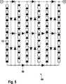
Ein entsprechendes Modul
Bei der Erläuterung des Ausführungsbeispiels wird als Material für den Träger
Insbesondere kann der Träger
Bei den Solarzellen
Die Frontseitenkontaktsolarzellen
Der Träger
Zum Verschalten der Solarzellen
Auch sind die Verbinder
Der Träger
In der
Der zweite Verbinder
Somit sind in der
Zum Verschalten wird der Abschnitt
Die in den Kanälen
Von den Busbars
Da die Verbindungselemente nicht zwischen der Auflagefläche
Dadurch, dass die Verbinder
Eine stoffschlüssige Verbindung zwischen den zweiten Verbindern
Die Verbindung wird dann hergestellt, wenn die ersten und zweiten Verbinder
Entsprechend erfolgt eine Verbindung zwischen den Rückseitenkontakten bzw. Busbars oder Pads mit den ersten Verbindern
Die Verbinder
In diesem Fall sind die ersten und zweiten Verbinder
Dieser Bereich in dem ersten Verbinder
Anhand der
Entsprechend können in dem Träger
Die ersten und zweiten Verbinder
Ein entsprechender Träger
Es besteht auch die Möglichkeit, eine aus Kunststoff bestehende elektrisch isolierende Schicht aufzubringen, die gegebenenfalls ein isolierendes Gewebe oder Vlies enthält, um eine Verstärkung zu erzielen.It is also possible to apply an existing plastic insulating layer, which optionally contains an insulating fabric or non-woven to achieve a gain.
Durch diese Maßnahme ist sichergestellt, dass die Solarzellen
Diesbezügliche Maßnahmen sind nicht zwingend erforderlich, wenn das Material des Trägers aus einem elektrisch isolierenden Material wie Pappe oder Karton besteht.Such measures are not mandatory if the material of the carrier is made of an electrically insulating material such as cardboard or cardboard.
Nach dem Verbinden der Solarzellen
Es besteht auch die Möglichkeit, die Solarzellen
Abschließend wird auf die Solarzellen
Ist die erfindungsgemäße Lehre zuvor anhand von Frontsolarkontaktzellen beschrieben worden, so ist hierdurch eine Beschränkung nicht zu sehen. Vielmehr sind auch zu Solarzellenmodulen zu verschaltende Rückseitenkontaktsolarzellen – auch Rückkontaktsolarzellen genannt – entsprechend der erfindungsgemäßen Lehre flächig auf Träger anordbar, wobei die Verbinder zwischen den zu verschaltenden Solarzellen in Aussparungen des Trägers verlaufen, die entsprechend zuvor erfolgter Erläuterungen ausgebildet sein können. Insoweit wird auf die zuvor erfolgte Beschreibung verwiesen. Dies gilt auch in Bezug auf die verwendeten Materialien sowie Ausgestaltungen.If the teaching according to the invention has been described above on the basis of frontolar contact cells, a restriction is not to be seen thereby. Rather, solar cell modules to be interconnected back contact solar cells - also known as back contact solar cells - can be arranged according to the teaching of the invention on a carrier surface, the connectors between the solar cells to be interconnected in recesses of the carrier, which may be formed according to previous explanations. In that regard, reference is made to the description above. This also applies with regard to the materials used and configurations.
In
Die den Durchgangsöffnungen
Zum Sammeln des Stroms ist auf der Frontseite
Entsprechend dem Stand der Technik werden die in Reihen und zur Rückseite der Solarzellen
Um die Solarzellen
Die Solarzelle
Anstelle einer der
Den
Durch die Anordnung der Durchgangsöffnungen
Dabei ist die Solarzelle
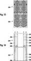
Nach
Aus den
Es ergibt sich ein langgestreckter S- oder Z-förmiger Verlauf eines jeden Verbinders
Es besteht auch die Möglichkeit, Verbinder kammartiger Geometrie zu benutzen, die einen Querschenkel und zu beiden Seiten von diesem verlaufende Längsschenkel aufweisen, wobei die Längsschenkel einer Seite mit parallel verlaufenden ersten Busbars wie p-Kontakten einer ersten Solarzelle und die Längsschenkel der anderen Seite mit parallel verlaufenden zweiten Busbars wie n-Kontakten einer mit der ersten Solarzelle zu verschaltenden zweiten Solarzelle verbunden sind. It is also possible to use connectors comb-like geometry having a transverse leg and on both sides extending from this longitudinal leg, wherein the longitudinal legs of one side with parallel first busbars such as p-contacts of a first solar cell and the longitudinal legs of the other side with parallel extending second busbars are connected as n-contacts of a second solar cell to be connected to the first solar cell.
ZITATE ENTHALTEN IN DER BESCHREIBUNG QUOTES INCLUDE IN THE DESCRIPTION
Diese Liste der vom Anmelder aufgeführten Dokumente wurde automatisiert erzeugt und ist ausschließlich zur besseren Information des Lesers aufgenommen. Die Liste ist nicht Bestandteil der deutschen Patent- bzw. Gebrauchsmusteranmeldung. Das DPMA übernimmt keinerlei Haftung für etwaige Fehler oder Auslassungen.This list of the documents listed by the applicant has been generated automatically and is included solely for the better information of the reader. The list is not part of the German patent or utility model application. The DPMA assumes no liability for any errors or omissions.
Zitierte PatentliteraturCited patent literature
- US 5972732 A[0017]US 5972732 A[0017]
- US 5951786 A[0017]US 5951786 A[0017]
- DE 102005057468 A[0021]DE 102005057468 A[0021]
- WO 2010/027265 A[0026]WO 2010/027265 A[0026]
Zitierte Nicht-PatentliteraturCited non-patent literature
- D. W. Eikelboom et al.[0010]DW Eikelboom et al.[0010]
- D. Thorp, et al “Methods of contacting multijunction silicon PV modules“, 14th European PVSEC, Barcelona, 1997, p[0013]D. Thorp, et al "Methods of Contacting multi junction silicon PV modules", 14th European PVSEC, Barcelona, 1997, p[0013]
- A. Schoenecker, et al “An industrial mc EWT-solar cell with screen-printed metallization”, 14th European PVSEC, Barcelona, 1997, p[0013]A. Schoenecker, et al "An industrial mc EWT solar cell with screen-printed metallization" 14th European PVSEC, Barcelona, 1997, p[0013]
- M. Späth, et al “Solder version of 8 inch back-contacted solar cells”, 15th PVSEC Shanghai, 2005, p.1003[0013]M. Späth, et al "Solder version of 8 inch back-contacted solar cells", 15th PVSEC Shanghai, 2005, p.1003[0013]
- F. Clement, et al “Processing and comprehensive characterization of screen-printed mc-Si metal wrap through (MWT) solar cells”, 22nd European PVSEC, 2007, Milano, p. 1399[0013]F. Clement, et al. "Processing and Comprehensive Characterization of Screen-printed MC-Si Metal Wrap-Through (MWT) Solar Cells", 22nd European PVSEC, 2007, Milano, p. 1399[0013]
- Y. Meydbray, et al “Solder Joint degradation in high efficiency all back contact solar cells”, 22nd European PVSEC, Milano, 2007, p. 2561[0013]Y. Meydbray, et al "Solder Joint Degradation in High Efficiency All Back Contact Solar Cells", 22nd European PVSEC, Milano, 2007, p. 2561[0013]
- U. Eitner, et al “A modelling approach to the optimization of interconnects for back contact cells by thermomechanical simulations of photovoltaic modules”, 23rd European PVSEC, Valencia, 2008, p. 2815[0013]U. Eitner, et al. "A Modeling Approach to the Optimization of Interfaces for Back Contact Cells by Thermomechanical Simulation of Photovoltaic Modules", 23rd European PVSEC, Valencia, 2008, p. 2815[0013]
- K. Nakamura, et al “Development of back contact Si solar cells and module in pilot production line”, 23rd European PVSEC, Valencia, 2008, p. 1006[0013]K. Nakamura, et al. "Development of back contact Si Solar Cells and Modules in Pilot Production Line", 23rd European PVSEC, Valencia, 2008, p. 1006[0013]
- D. W. Eikelboom, et al “Conductive adhesives for interconnection of busbar-less emitter wrapthrough solar cells on a structured metal foil”, 17th PVSEC Fukuoka Japan, 2001, p.1547[0015]DW Eikelboom, et al. "Conductive adhesives for interconnection of busbarless emitters through solar cells on a structured metal foil", 17th PVSEC Fukuoka Japan, 2001, p.1547[0015]
- M. Späth, et al “A novel module assembly line using back-contact solar cells”, 23rd European PVSEC, Valencia, 2008, p. 2917[0016]M. Späth, et al "A novel module assembly line using back-contact solar cells", 23rd European PVSEC, Valencia, 2008, p. 2917[0016]
Claims (21)
Translated fromGermanPriority Applications (4)
| Application Number | Priority Date | Filing Date | Title |
|---|---|---|---|
| DE102011055754.7ADE102011055754B4 (en) | 2011-06-01 | 2011-11-28 | Solar cell module and method for connecting solar cells |
| CN201280026117.6ACN103650154B (en) | 2011-06-01 | 2012-05-29 | Solar module and the method for the wiring for solaode |
| PCT/EP2012/060025WO2012163908A2 (en) | 2011-06-01 | 2012-05-29 | Solar cell module and method for connecting solar cells |
| EP12730407.9AEP2715795A2 (en) | 2011-06-01 | 2012-05-29 | Solar cell module and method for connecting solar cells |
Applications Claiming Priority (3)
| Application Number | Priority Date | Filing Date | Title |
|---|---|---|---|
| DE102011050795.7 | 2011-06-01 | ||
| DE102011050795 | 2011-06-01 | ||
| DE102011055754.7ADE102011055754B4 (en) | 2011-06-01 | 2011-11-28 | Solar cell module and method for connecting solar cells |
Publications (2)
| Publication Number | Publication Date |
|---|---|
| DE102011055754A1true DE102011055754A1 (en) | 2012-12-06 |
| DE102011055754B4 DE102011055754B4 (en) | 2022-12-29 |
Family
ID=47173123
Family Applications (1)
| Application Number | Title | Priority Date | Filing Date |
|---|---|---|---|
| DE102011055754.7AActiveDE102011055754B4 (en) | 2011-06-01 | 2011-11-28 | Solar cell module and method for connecting solar cells |
Country Status (3)
| Country | Link |
|---|---|
| EP (1) | EP2715795A2 (en) |
| DE (1) | DE102011055754B4 (en) |
| WO (1) | WO2012163908A2 (en) |
Cited By (9)
| Publication number | Priority date | Publication date | Assignee | Title |
|---|---|---|---|---|
| CN103337531A (en)* | 2013-03-22 | 2013-10-02 | 横店集团东磁股份有限公司 | Roof solar energy photovoltaic component |
| WO2016184456A1 (en)* | 2015-05-19 | 2016-11-24 | Hanwha Q Cells Gmbh | Solar module with central interconnection |
| DE102018103740A1 (en) | 2018-02-20 | 2019-08-22 | Turck Duotec GmbH | Arrangement of solar elements and method for interconnecting solar elements |
| DE102018112104A1 (en)* | 2018-05-18 | 2019-11-21 | Institut Für Solarenergieforschung Gmbh | LAMINATE FOIL AND METHOD OF EMBEDDING SOLAR CELLS FOR FORMING A PHOTOVOLTAIC MODULE AND METHOD FOR MANUFACTURING A LAMINATE FOIL |
| CN110726262A (en)* | 2019-10-22 | 2020-01-24 | 陕西科技大学 | A light-to-heat conversion film, its preparation method, and a double-layer evaporation structure for solar steam generation |
| EP3017520B1 (en) | 2013-07-05 | 2020-10-14 | REC Solar Pte. Ltd. | Solar cell assembly |
| WO2022089947A1 (en)* | 2020-10-26 | 2022-05-05 | Fraunhofer-Gesellschaft zur Förderung der angewandten Forschung e. V. | Solar cell module |
| WO2022171602A1 (en)* | 2021-02-10 | 2022-08-18 | Hanwha Q Cells Gmbh | Photovoltaic module and method for producing same |
| WO2023099771A1 (en)* | 2021-12-03 | 2023-06-08 | Fraunhofer-Gesellschaft zur Förderung der angewandten Forschung e. V. | Solar-cell module |
Families Citing this family (1)
| Publication number | Priority date | Publication date | Assignee | Title |
|---|---|---|---|---|
| GB2563046A (en) | 2017-06-01 | 2018-12-05 | Rec Solar Pte Ltd | Cost effective frame design for thinner wafers |
Citations (20)
| Publication number | Priority date | Publication date | Assignee | Title |
|---|---|---|---|---|
| US3874931A (en)* | 1969-12-12 | 1975-04-01 | Communications Satellite Corp | Solar cell array |
| JPH09153634A (en)* | 1995-11-29 | 1997-06-10 | Sony Corp | Transparent substrate incorporating solar battery electrode, manufacture of the same and solar battery device |
| US5951786A (en) | 1997-12-19 | 1999-09-14 | Sandia Corporation | Laminated photovoltaic modules using back-contact solar cells |
| US5972732A (en) | 1997-12-19 | 1999-10-26 | Sandia Corporation | Method of monolithic module assembly |
| US20020134422A1 (en)* | 2001-03-20 | 2002-09-26 | The Boeing Company | Solar tile and associated method for fabricating the same |
| DE102005057468A1 (en) | 2005-11-30 | 2007-05-31 | Solarwatt Solar-Systeme Ag | Plate-shaped frameless photovoltaic solar module has solar cells embedded between cover and rear materials and a rear strengthening structure |
| DE102006052018A1 (en)* | 2006-11-03 | 2008-05-15 | Fraunhofer-Gesellschaft zur Förderung der angewandten Forschung e.V. | Solar cell and solar cell module with improved backside electrodes as well as process and fabrication |
| US20090065043A1 (en)* | 2006-02-22 | 2009-03-12 | Jean-Christophe Hadorn | Method of coupling photovoltaic cells and film for implementing it |
| JP2009076739A (en)* | 2007-09-21 | 2009-04-09 | Kyocera Corp | Solar cell module and manufacturing method thereof |
| DE102008012286A1 (en)* | 2008-03-03 | 2009-09-24 | Fraunhofer-Gesellschaft zur Förderung der angewandten Forschung e.V. | Solar module i.e. photovoltaic component, for directly generating electrical current from sunlight, has plastic carrier providing metallic electrical connecting structure for electrical connection to solar cell arrangement |
| DE202008011461U1 (en)* | 2008-08-28 | 2010-01-07 | Aleo Solar Ag | Electric solar cell connections and photovoltaic solar modules |
| WO2010027265A2 (en) | 2008-09-05 | 2010-03-11 | Solland Solar Energy Holding B.V. | Method of monolithic photo-voltaic module assembly |
| DE102008055475A1 (en)* | 2008-12-04 | 2010-06-10 | Azur Space Solar Power Gmbh | Solar cells i.e. concentrator solar cells, arrangement for use in e.g. high-concentrated photo-voltaic system, has concentrator solar cells interconnected in area uncovered by enclosed hollows, base section, covers and cover substrate |
| DE102009014491A1 (en)* | 2009-03-23 | 2010-09-30 | Rawema Countertrade Handelsgesellschaft Mbh | Collector for heating fluid by solar energy, has inlet area for supplying fluid that is heated, where discharge area discharges heated fluid in collector, and fluid flow area is provided between inlet area and discharge area |
| DE102009002823A1 (en)* | 2009-05-05 | 2010-11-18 | Komax Holding Ag | Solar cell, this solar cell comprehensive solar module and method for their preparation and for producing a contact foil |
| US20100307582A1 (en)* | 2009-06-05 | 2010-12-09 | Semiconductor Energy Laboratory Co., Ltd. | Photoelectric conversion device |
| DE102009023901A1 (en)* | 2009-06-04 | 2010-12-16 | Fraunhofer-Gesellschaft zur Förderung der angewandten Forschung e.V. | Photovoltaic module with flat cell connector |
| DE102010004112A1 (en)* | 2009-06-29 | 2010-12-30 | Bosch Solar Energy Ag | Method for producing a foil-type electrical connector for solar cells, connecting element produced in this way and method for electrically connecting at least two solar cells to a solar module |
| DE102009026149A1 (en)* | 2009-07-10 | 2011-01-27 | Eppsteinfoils Gmbh & Co.Kg | Composite system for photovoltaic modules |
| US20110067751A1 (en)* | 2008-04-29 | 2011-03-24 | Meakin David H | Photovoltaic modules manufactured using monolithic module assembly techniques |
Family Cites Families (5)
| Publication number | Priority date | Publication date | Assignee | Title |
|---|---|---|---|---|
| GB1554507A (en) | 1977-04-28 | 1979-10-24 | Tideland Signal Corp | Enclosure for solar cells |
| US4636577A (en)* | 1983-08-29 | 1987-01-13 | Thomas & Betts Corporation | Solar panel module and support therefor |
| US4832755A (en)* | 1987-08-11 | 1989-05-23 | The Boeing Company | Glass encapsulation of solar cell arrays to minimize voltage/plasma interaction effects in a space environment |
| GB2247564B (en) | 1990-08-16 | 1995-01-04 | Eev Ltd | A solar cell arrangement |
| DE102008018360A1 (en) | 2008-04-11 | 2009-10-15 | Seho Systemtechnik Gmbh | Method for fitting solar cells on connecting support of solar cell module, involves connecting solar cells with connecting support, where connecting support is provided with conductive paths |
- 2011
- 2011-11-28DEDE102011055754.7Apatent/DE102011055754B4/enactiveActive
- 2012
- 2012-05-29EPEP12730407.9Apatent/EP2715795A2/ennot_activeWithdrawn
- 2012-05-29WOPCT/EP2012/060025patent/WO2012163908A2/enactiveApplication Filing
Patent Citations (20)
| Publication number | Priority date | Publication date | Assignee | Title |
|---|---|---|---|---|
| US3874931A (en)* | 1969-12-12 | 1975-04-01 | Communications Satellite Corp | Solar cell array |
| JPH09153634A (en)* | 1995-11-29 | 1997-06-10 | Sony Corp | Transparent substrate incorporating solar battery electrode, manufacture of the same and solar battery device |
| US5951786A (en) | 1997-12-19 | 1999-09-14 | Sandia Corporation | Laminated photovoltaic modules using back-contact solar cells |
| US5972732A (en) | 1997-12-19 | 1999-10-26 | Sandia Corporation | Method of monolithic module assembly |
| US20020134422A1 (en)* | 2001-03-20 | 2002-09-26 | The Boeing Company | Solar tile and associated method for fabricating the same |
| DE102005057468A1 (en) | 2005-11-30 | 2007-05-31 | Solarwatt Solar-Systeme Ag | Plate-shaped frameless photovoltaic solar module has solar cells embedded between cover and rear materials and a rear strengthening structure |
| US20090065043A1 (en)* | 2006-02-22 | 2009-03-12 | Jean-Christophe Hadorn | Method of coupling photovoltaic cells and film for implementing it |
| DE102006052018A1 (en)* | 2006-11-03 | 2008-05-15 | Fraunhofer-Gesellschaft zur Förderung der angewandten Forschung e.V. | Solar cell and solar cell module with improved backside electrodes as well as process and fabrication |
| JP2009076739A (en)* | 2007-09-21 | 2009-04-09 | Kyocera Corp | Solar cell module and manufacturing method thereof |
| DE102008012286A1 (en)* | 2008-03-03 | 2009-09-24 | Fraunhofer-Gesellschaft zur Förderung der angewandten Forschung e.V. | Solar module i.e. photovoltaic component, for directly generating electrical current from sunlight, has plastic carrier providing metallic electrical connecting structure for electrical connection to solar cell arrangement |
| US20110067751A1 (en)* | 2008-04-29 | 2011-03-24 | Meakin David H | Photovoltaic modules manufactured using monolithic module assembly techniques |
| DE202008011461U1 (en)* | 2008-08-28 | 2010-01-07 | Aleo Solar Ag | Electric solar cell connections and photovoltaic solar modules |
| WO2010027265A2 (en) | 2008-09-05 | 2010-03-11 | Solland Solar Energy Holding B.V. | Method of monolithic photo-voltaic module assembly |
| DE102008055475A1 (en)* | 2008-12-04 | 2010-06-10 | Azur Space Solar Power Gmbh | Solar cells i.e. concentrator solar cells, arrangement for use in e.g. high-concentrated photo-voltaic system, has concentrator solar cells interconnected in area uncovered by enclosed hollows, base section, covers and cover substrate |
| DE102009014491A1 (en)* | 2009-03-23 | 2010-09-30 | Rawema Countertrade Handelsgesellschaft Mbh | Collector for heating fluid by solar energy, has inlet area for supplying fluid that is heated, where discharge area discharges heated fluid in collector, and fluid flow area is provided between inlet area and discharge area |
| DE102009002823A1 (en)* | 2009-05-05 | 2010-11-18 | Komax Holding Ag | Solar cell, this solar cell comprehensive solar module and method for their preparation and for producing a contact foil |
| DE102009023901A1 (en)* | 2009-06-04 | 2010-12-16 | Fraunhofer-Gesellschaft zur Förderung der angewandten Forschung e.V. | Photovoltaic module with flat cell connector |
| US20100307582A1 (en)* | 2009-06-05 | 2010-12-09 | Semiconductor Energy Laboratory Co., Ltd. | Photoelectric conversion device |
| DE102010004112A1 (en)* | 2009-06-29 | 2010-12-30 | Bosch Solar Energy Ag | Method for producing a foil-type electrical connector for solar cells, connecting element produced in this way and method for electrically connecting at least two solar cells to a solar module |
| DE102009026149A1 (en)* | 2009-07-10 | 2011-01-27 | Eppsteinfoils Gmbh & Co.Kg | Composite system for photovoltaic modules |
Non-Patent Citations (12)
| Title |
|---|
| A. Schoenecker, et al "An industrial mc EWT-solar cell with screen-printed metallization", 14th European PVSEC, Barcelona, 1997, p |
| D. Thorp, et al "Methods of contacting multijunction silicon PV modules", 14th European PVSEC, Barcelona, 1997, p |
| D. W. Eikelboom et al. |
| D. W. Eikelboom, et al "Conductive adhesives for interconnection of busbar-less emitter wrapthrough solar cells on a structured metal foil", 17th PVSEC Fukuoka Japan, 2001, p.1547 |
| DE JONG, P. C. [u.a.]: Single-step laminated full-size PV modules made with back-contacted MC-Si cells. In: Proceedings of the 19th European Photovoltaic Solar Energy Conference, 2004, S. 2145 - 2148.* |
| DE JONG, P. C. [u.a.]: Single-step laminated full-size PV modules made with back-contacted MC-Si cells. In: Proceedings of the 19th European Photovoltaic Solar Energy Conference, 2004, S. 2145 – 2148. |
| F. Clement, et al "Processing and comprehensive characterization of screen-printed mc-Si metal wrap through (MWT) solar cells", 22nd European PVSEC, 2007, Milano, p. 1399 |
| K. Nakamura, et al "Development of back contact Si solar cells and module in pilot production line", 23rd European PVSEC, Valencia, 2008, p. 1006 |
| M. Späth, et al "A novel module assembly line using back-contact solar cells", 23rd European PVSEC, Valencia, 2008, p. 2917 |
| M. Späth, et al "Solder version of 8 inch back-contacted solar cells", 15th PVSEC Shanghai, 2005, p.1003 |
| U. Eitner, et al "A modelling approach to the optimization of interconnects for back contact cells by thermomechanical simulations of photovoltaic modules", 23rd European PVSEC, Valencia, 2008, p. 2815 |
| Y. Meydbray, et al "Solder Joint degradation in high efficiency all back contact solar cells", 22nd European PVSEC, Milano, 2007, p. 2561 |
Cited By (13)
| Publication number | Priority date | Publication date | Assignee | Title |
|---|---|---|---|---|
| CN103337531A (en)* | 2013-03-22 | 2013-10-02 | 横店集团东磁股份有限公司 | Roof solar energy photovoltaic component |
| EP3017520B1 (en) | 2013-07-05 | 2020-10-14 | REC Solar Pte. Ltd. | Solar cell assembly |
| US12212146B2 (en) | 2013-07-05 | 2025-01-28 | Rec Solar Pte. Ltd. | Solar cell assembly |
| WO2016184456A1 (en)* | 2015-05-19 | 2016-11-24 | Hanwha Q Cells Gmbh | Solar module with central interconnection |
| WO2019162254A1 (en) | 2018-02-20 | 2019-08-29 | Turck Duotec GmbH | Arrangement of solar elements and method for interconnecting solar elements |
| DE102018103740A1 (en) | 2018-02-20 | 2019-08-22 | Turck Duotec GmbH | Arrangement of solar elements and method for interconnecting solar elements |
| DE102018112104A1 (en)* | 2018-05-18 | 2019-11-21 | Institut Für Solarenergieforschung Gmbh | LAMINATE FOIL AND METHOD OF EMBEDDING SOLAR CELLS FOR FORMING A PHOTOVOLTAIC MODULE AND METHOD FOR MANUFACTURING A LAMINATE FOIL |
| CN110726262A (en)* | 2019-10-22 | 2020-01-24 | 陕西科技大学 | A light-to-heat conversion film, its preparation method, and a double-layer evaporation structure for solar steam generation |
| CN110726262B (en)* | 2019-10-22 | 2020-10-27 | 陕西科技大学 | Photo-thermal conversion film, preparation method thereof and double-layer evaporation structure for solar steam generation |
| WO2022089947A1 (en)* | 2020-10-26 | 2022-05-05 | Fraunhofer-Gesellschaft zur Förderung der angewandten Forschung e. V. | Solar cell module |
| US12328953B2 (en) | 2020-10-26 | 2025-06-10 | Fraunhofer-Gesellschaft zur Förderung der angewandten Forschung e.V. | Solar cell module |
| WO2022171602A1 (en)* | 2021-02-10 | 2022-08-18 | Hanwha Q Cells Gmbh | Photovoltaic module and method for producing same |
| WO2023099771A1 (en)* | 2021-12-03 | 2023-06-08 | Fraunhofer-Gesellschaft zur Förderung der angewandten Forschung e. V. | Solar-cell module |
Also Published As
| Publication number | Publication date |
|---|---|
| WO2012163908A3 (en) | 2013-03-21 |
| DE102011055754B4 (en) | 2022-12-29 |
| WO2012163908A2 (en) | 2012-12-06 |
| EP2715795A2 (en) | 2014-04-09 |
| CN103650154A (en) | 2014-03-19 |
Similar Documents
| Publication | Publication Date | Title |
|---|---|---|
| DE102011055754B4 (en) | Solar cell module and method for connecting solar cells | |
| DE112016003768B4 (en) | SOLAR PANEL | |
| EP2308090B1 (en) | Thin-film solar module which is contact-connected on one side and has an internal contact layer | |
| EP2517265B1 (en) | Solar panel comprising a printed circuit and method of production and use thereof | |
| KR20170048460A (en) | Main-gate-free and high efficiency back contact solar cell module, assembly and preparation process | |
| EP2577740A1 (en) | Method for contacting and connecting solar cells and solar cell combination produced by means of said method | |
| WO1999048136A2 (en) | Solar cell arrangement | |
| DE102014118332A1 (en) | photovoltaic module | |
| CN104269462B (en) | Back contact solar cell back sheet without main grids, back contact solar cell assembly without main grids and manufacturing technology | |
| WO2009135819A2 (en) | Method for producing a monocrystalline solar cell | |
| EP2817830A2 (en) | Method and device for producing a solar module and a solar module having flexible thin-film solar cells | |
| DE102012003455A1 (en) | Method for producing thin film solar module, involves providing sequence of flexible thin-film solar cells for designing side portions in electrically conductive terminals and forming photovoltaic active layer with electrical conductor | |
| DE102018105472A1 (en) | Process for producing a photovoltaic solar cell, photovoltaic solar cell and photovoltaic module | |
| DE102010007131A1 (en) | Solar cell string and method for its production | |
| DE102010043006A1 (en) | Photovoltaic device | |
| NL2015899B1 (en) | Interconnection of back-contacted solar cell, a solar panel having such interconnection. | |
| DE102010016976A1 (en) | Method for interconnecting solar cells, involves assigning back contact solar cells on second and third electric guards to contact back led front face region according to back contact solar cells in series which are interconnected | |
| DE102011051511A1 (en) | Rear contact solar cell and method for producing such | |
| WO2012128284A1 (en) | Rear surface electrode-type solar cell, manufacturing method for rear surface electrode-type solar cell, and solar cell module | |
| CN204088340U (en) | Without main grid high efficiency back contact solar cell backboard | |
| CN204088345U (en) | Without main grid high efficiency back contact solar cell module and assembly | |
| DE102011052318B4 (en) | Solar module with contact foil and solar module manufacturing process | |
| DE202013003610U1 (en) | solar cell module | |
| DE102011056632A1 (en) | Method for forming a front side metallization of a solar cell and solar cell | |
| AT511628B1 (en) | PHOTOVOLTAIC MODULE WITH SEVERAL SOLAR CELLS |
Legal Events
| Date | Code | Title | Description |
|---|---|---|---|
| R163 | Identified publications notified | ||
| R081 | Change of applicant/patentee | Owner name:FRAUNHOFER-GESELLSCHAFT ZUR FOERDERUNG DER ANG, DE Free format text:FORMER OWNER: SCHOTT SOLAR AG, 55122 MAINZ, DE Effective date:20130808 | |
| R082 | Change of representative | Representative=s name:STOFFREGEN, HANS-HERBERT, DIPL.-PHYS. DR.RER.N, DE Effective date:20130808 | |
| R012 | Request for examination validly filed | ||
| R016 | Response to examination communication | ||
| R018 | Grant decision by examination section/examining division | ||
| R020 | Patent grant now final | ||
| R079 | Amendment of ipc main class | Free format text:PREVIOUS MAIN CLASS: H01L0031050000 Ipc:H10F0019900000 |