DE102011050983A1 - Closing plugs for pharmaceutical applications - Google Patents
Closing plugs for pharmaceutical applicationsDownload PDFInfo
- Publication number
- DE102011050983A1 DE102011050983A1DE102011050983ADE102011050983ADE102011050983A1DE 102011050983 A1DE102011050983 A1DE 102011050983A1DE 102011050983 ADE102011050983 ADE 102011050983ADE 102011050983 ADE102011050983 ADE 102011050983ADE 102011050983 A1DE102011050983 A1DE 102011050983A1
- Authority
- DE
- Germany
- Prior art keywords
- sealing
- projection
- closure
- sealing flange
- flange
- Prior art date
- Legal status (The legal status is an assumption and is not a legal conclusion. Google has not performed a legal analysis and makes no representation as to the accuracy of the status listed.)
- Withdrawn
Links
- 238000007789sealingMethods0.000claimsabstractdescription197
- 239000003708ampulSubstances0.000claimsabstractdescription15
- 239000003814drugSubstances0.000claimsabstractdescription9
- 239000008177pharmaceutical agentSubstances0.000claimsabstractdescription4
- 238000007373indentationMethods0.000claimsdescription20
- 230000000694effectsEffects0.000claimsdescription15
- 238000003780insertionMethods0.000claimsdescription5
- 230000037431insertionEffects0.000claimsdescription5
- 230000001154acute effectEffects0.000claimsdescription3
- 230000015572biosynthetic processEffects0.000claims1
- 238000005755formation reactionMethods0.000claims1
- 230000000007visual effectEffects0.000claims1
- 238000013461designMethods0.000description12
- 238000004108freeze dryingMethods0.000description10
- 239000000463materialSubstances0.000description7
- 238000000034methodMethods0.000description4
- 230000003313weakening effectEffects0.000description4
- 239000011324beadSubstances0.000description3
- 229940079593drugDrugs0.000description3
- 230000000630rising effectEffects0.000description3
- 241000196324EmbryophytaSpecies0.000description2
- 230000006835compressionEffects0.000description2
- 238000007906compressionMethods0.000description2
- 230000005489elastic deformationEffects0.000description2
- 239000007788liquidSubstances0.000description2
- 238000004519manufacturing processMethods0.000description2
- 229920002725thermoplastic elastomerPolymers0.000description2
- 238000012549trainingMethods0.000description2
- BUHVIAUBTBOHAG-FOYDDCNASA-N(2r,3r,4s,5r)-2-[6-[[2-(3,5-dimethoxyphenyl)-2-(2-methylphenyl)ethyl]amino]purin-9-yl]-5-(hydroxymethyl)oxolane-3,4-diolChemical compoundCOC1=CC(OC)=CC(C(CNC=2C=3N=CN(C=3N=CN=2)[C@H]2[C@@H]([C@H](O)[C@@H](CO)O2)O)C=2C(=CC=CC=2)C)=C1BUHVIAUBTBOHAG-FOYDDCNASA-N0.000description1
- 244000043261Hevea brasiliensisSpecies0.000description1
- 239000000654additiveSubstances0.000description1
- 238000013459approachMethods0.000description1
- 230000007423decreaseEffects0.000description1
- 238000011161developmentMethods0.000description1
- 238000001035dryingMethods0.000description1
- 229920001971elastomerPolymers0.000description1
- 230000001788irregularEffects0.000description1
- 238000012986modificationMethods0.000description1
- 230000004048modificationEffects0.000description1
- 229920003052natural elastomerPolymers0.000description1
- 229920001194natural rubberPolymers0.000description1
- 230000002093peripheral effectEffects0.000description1
- 239000004033plasticSubstances0.000description1
- 239000000843powderSubstances0.000description1
- 238000002360preparation methodMethods0.000description1
- 230000000284resting effectEffects0.000description1
- 230000007704transitionEffects0.000description1
- 239000002699waste materialSubstances0.000description1
Images


Classifications
- B—PERFORMING OPERATIONS; TRANSPORTING
- B65—CONVEYING; PACKING; STORING; HANDLING THIN OR FILAMENTARY MATERIAL
- B65D—CONTAINERS FOR STORAGE OR TRANSPORT OF ARTICLES OR MATERIALS, e.g. BAGS, BARRELS, BOTTLES, BOXES, CANS, CARTONS, CRATES, DRUMS, JARS, TANKS, HOPPERS, FORWARDING CONTAINERS; ACCESSORIES, CLOSURES, OR FITTINGS THEREFOR; PACKAGING ELEMENTS; PACKAGES
- B65D39/00—Closures arranged within necks or pouring openings or in discharge apertures, e.g. stoppers
- B65D39/0005—Closures arranged within necks or pouring openings or in discharge apertures, e.g. stoppers made in one piece
- B—PERFORMING OPERATIONS; TRANSPORTING
- B65—CONVEYING; PACKING; STORING; HANDLING THIN OR FILAMENTARY MATERIAL
- B65D—CONTAINERS FOR STORAGE OR TRANSPORT OF ARTICLES OR MATERIALS, e.g. BAGS, BARRELS, BOTTLES, BOXES, CANS, CARTONS, CRATES, DRUMS, JARS, TANKS, HOPPERS, FORWARDING CONTAINERS; ACCESSORIES, CLOSURES, OR FITTINGS THEREFOR; PACKAGING ELEMENTS; PACKAGES
- B65D51/00—Closures not otherwise provided for
- B65D51/002—Closures to be pierced by an extracting-device for the contents and fixed on the container by separate retaining means
- B—PERFORMING OPERATIONS; TRANSPORTING
- B65—CONVEYING; PACKING; STORING; HANDLING THIN OR FILAMENTARY MATERIAL
- B65D—CONTAINERS FOR STORAGE OR TRANSPORT OF ARTICLES OR MATERIALS, e.g. BAGS, BARRELS, BOTTLES, BOXES, CANS, CARTONS, CRATES, DRUMS, JARS, TANKS, HOPPERS, FORWARDING CONTAINERS; ACCESSORIES, CLOSURES, OR FITTINGS THEREFOR; PACKAGING ELEMENTS; PACKAGES
- B65D51/00—Closures not otherwise provided for
- B65D51/24—Closures not otherwise provided for combined or co-operating with auxiliary devices for non-closing purposes
- B65D51/241—Closures not otherwise provided for combined or co-operating with auxiliary devices for non-closing purposes provided with freeze-drying means
Landscapes
- Engineering & Computer Science (AREA)
- Mechanical Engineering (AREA)
- Closures For Containers (AREA)
- Medical Preparation Storing Or Oral Administration Devices (AREA)
Abstract
Translated fromGermanDescription
Translated fromGermanDie Erfindung betrifft einen Verschlussstopfen für pharmazeutische Anwendungen, insbesondere zum dichtenden Verschließen eines ein pharmazeutisches Mittel enthaltenden Behältnisses, bspw. zum Verschluss einer ein Medikament enthaltenden Ampulle, mit einem Dichtflansch zum dichtenden Aufsitzen auf einer Stirnfläche einer Verschlussmündung des Behältnisses, wobei der Dichtflansch eine untere Dichtfläche und eine an einem am weitesten nach unten vorragenden Bereich anliegende, sich senkrecht zu einer Mittelachse des Verschlussstopfens erstreckende Begrenzungsebene aufweist, einem Eingriffsabschnitt, der sich unterhalb des Dichtflansches erstreckt und mit geringerer radialer Erstreckung als der Dichtflansch ausgebildet ist, und, bevorzugt, einem Handhabungsabschnitt, der sich oberhalb des Dichtflansches erstreckt, wobei weiter an dem Eingriffsabschnitt ein umlaufender Dichtvorsprung ausgebildet ist, der gegenüber einem sich zunächst unterhalb des Dichtflansches anschließenden, einen Abschnittsradius aufweisenden Axialabschnitt des Eingriffabschnitts um ein Radialmaß vorsteht.The invention relates to a sealing plug for pharmaceutical applications, in particular for sealingly closing a container containing a pharmaceutical agent, for example for closing an ampoule containing a medicament, with a sealing flange for sealing seating on an end face of a closure mouth of the container, wherein the sealing flange has a lower sealing surface and a limiting plane adjacent to a downwardly projecting portion extending perpendicular to a central axis of the sealing plug, an engaging portion extending below the sealing flange and having a smaller radial extent than the sealing flange, and, preferably, a handling portion; which extends above the sealing flange, wherein further on the engagement portion, a circumferential sealing projection is formed, which is opposite to a first below the sealing flange, ei NEN section radius having axial portion of the engaging portion protrudes by a radial dimension.
Derartige Verschlussstopfen sind bereits in verschiedener Ausgestaltung bekannt geworden. Es wird bspw. auf die
Derartige Verschlussstopfen finden unter anderem Verwendung in Gefriertrocknungsverfahren. Insbesondere bei solchen Gefriertrocknungsverfahren, aber auch allgemein, ist ein Bedürfnis gegeben, den Verschlussstopfen bei guter Abdichtungsleistung vorteilhaft aufbringen zu können.Such sealing plugs find use, inter alia, in freeze-drying processes. In particular, in such freeze-drying method, but also in general, there is a need to be able to apply the closure plug with good sealing performance advantageous.
Diese Verschlussstopfen sind in der Regel rotationssymmetrisch zu einer Mittelachse ausgebildet.These sealing plugs are generally formed rotationally symmetrical to a central axis.
Hiervon ausgehend beschäftigt sich die Erfindung mit der Aufgabe, einen Verschlussstopfen für pharmazeutische Anwendungen anzugeben, der hinsichtlich des Aufbringens auf ein entsprechendes Behältnis und das Erreichen der Verschlussstellung vorteilhaft ausgebildet ist.On this basis, the invention has the object to provide a sealing plug for pharmaceutical applications, which is advantageously designed with respect to the application to a corresponding container and the achievement of the closed position.
Eine mögliche Lösung der Aufgabe ist nach einem ersten Erfindungsgedanken bei einem Gegenstand gegeben, der insbesondere die Merkmale aufweist, dass der Dichtvorsprung vertikal zumindest bezüglich seines Fußabschnittes in Überdeckung zu einem an dem Dichtflansch gegenüber der Begrenzungsebene ausgebildeten Rücksprungbereich ist. Es handelt sich also um einen Bereich, der in Bezug auf die Dichtfläche axial weiter oben befindlich ist als die Begrenzungsebene. Dies kann auf verschiedene Weise erreicht sein. Bspw. durch eine Schwächung des Flansches in diesem Bereich oder durch eine im Querschnitt vorgepfeilte, d. h. dass im Querschnitt ein radial äußerer Bereich weiter nach unten ragt als ein radial innerer Bereich des Dichtflansches, Gestaltung des Dichtflansches. In beiden Fällen wird erreicht, dass der im Verschlusszustand „aktive”, d. h. der tatsächlich dichtend wirkende, Flächenanteil der Dichtfläche auf einen mehr radial außen liegenden Bereich des Dichtflansches konzentriert ist. Da sich im Überdeckungsbereich zu dem Dichtvorsprung ohnehin, bis auf eine gewisse zur Erzielung der Dichtwirkung erforderliche und gewünschte Komprimierung des Dichtvorsprunges, im Verschlusszustand der Öffnungsquerschnitt der Mündung des Behältnisses befindet, ist eine ebenengleiche Gestaltung des Flansches in diesem Bereich nicht erforderlich.A possible solution of the problem is given according to a first inventive concept in an article, which in particular has the features that the sealing projection is vertically at least with respect to its foot portion in overlap to a formed on the sealing flange against the boundary plane return area. It is therefore an area that is located axially higher in relation to the sealing surface than the boundary plane. This can be achieved in various ways. For example. by a weakening of the flange in this area or by a pre-arrowed in cross-section, d. H. in that a radially outer region protrudes further downwards in cross-section than a radially inner region of the sealing flange, design of the sealing flange. In both cases it is achieved that in the closed state "active", d. H. the actual sealing effect, surface portion of the sealing surface is concentrated on a more radially outer region of the sealing flange. Since in the overlap region to the sealing projection anyway, except for a certain required to achieve the sealing effect and desired compression of the sealing projection, in the closed state of the opening cross section of the mouth of the container, a planar design of the flange in this area is not required.
Eine weitere mögliche Lösung der Aufgabe ist nach einem weiteren Erfindungsgedanken bei einem Gegenstand gegeben, der insbesondere die Merkmale aufweist, dass eine der äußeren Grenze des Radialmaßes, um welches der Dichtvorsprung gegenüber einem sich oberhalb des Dichtvorsprungs befindlichen Axialabschnitt des Eingriffsabschnittes vorsteht, entsprechende radiale Erstreckung, von der zentralen Achse ausgehend, bezogen auf einen geringsten Abschnittsradius, dem 1,05-fachen oder mehr entspricht, und dass ein Axialmaß des Dichtvorsprunges, gemessen entlang einer Parallelen zu der Mittellinie des Verschlussstopfens, wobei die Parallele ober- und/oder unterseitig des Dichtvorsprungs eine Tangente zu dem angrenzenden Bereich des Axialabschnittes oder zu einem Bereich eines sich ggf. unterseitig des Dichtvorsprungs erstreckenden Unterabschnitt des Eingriffsabschnittes bildet, und zwar an dem Bereich, oder ggf. beiden, zu dem sich, von radial außen kommend, zunächst die tangentiale Anlage ergibt, dem 0,5-fachen oder mehr der Differenz des Radialmaßes zu dem geringsten Abschnittsradius entspricht.A further possible solution to the problem is given according to a further inventive idea in an article, which in particular has the features that one of the outer boundary of the radial dimension, which projects beyond the sealing projection against a located above the sealing projection axial portion of the engagement portion corresponding radial extent, from the central axis, based on a smallest sectional radius corresponding to 1.05 times or more, and that an axial dimension of the sealing projection, measured along a parallels to the center line of the sealing plug, the parallel upper and / or lower side of the sealing projection a tangent to the adjacent region of the axial section or to a region of a possibly underside of the sealing projection extending Subsection of the engagement portion forms, namely at the area, or possibly both, to which, coming from radially outside, initially the tangential system results, which corresponds to 0.5 times or more of the difference of the radial dimension to the lowest section radius.
Diese Gestaltung zeichnet sich durch einen vergleichsweise radial weit vorstehenden Dichtvorsprung und entsprechend gegenüber diesem größten Radialmaß des Dichtvorsprungs zurückweichenden Axialabschnitt aus. Hierdurch wird eine vergleichsweise starke Belastung, im Verschlusszustand, an dem Dichtvorsprung erreicht und damit bezogen auf den Dichtvorsprung eine hohe Dichtwirkung.This design is characterized by a comparatively radially far projecting sealing projection and corresponding to this largest radial dimension of the sealing projection receding axial portion. As a result, a comparatively strong load, in the closed state, is achieved at the sealing projection and thus with respect to the sealing projection a high sealing effect.
Weitere Merkmale der Erfindung sind nachstehend, auch in der Figurenbeschreibung und der Zeichnung, oftmals in ihrer bevorzugten Zuordnung zu den bereits vorstehend erläuterten Anspruchskonzepten beschrieben bzw. dargestellt, sie können aber auch in einer Zuordnung zu nur einem oder mehreren einzelnen Merkmalen, die hier beschrieben oder zeichnerisch dargestellt sind, oder in einem anderen Gesamtkonzept oder unabhängig von Bedeutung sein.Further features of the invention are described below, also in the figure description and the drawing, often in their preferred assignment to the already explained above claim concepts or illustrated, but they can also be assigned to only one or more individual features described here or are represented graphically, or in another overall concept or independently of importance.
Zunächst ist es im Rahmen der Erfindung möglich, dass auch beide vorstehend schon beschriebenen Merkmalskomplexe zusammengefasst an einem derartigen Verschlussstopfen verwirklicht sind.First, it is possible in the context of the invention that both feature complexes already described above are realized in a summarized manner on such a closure plug.
Bei einem hier beschriebenen Verschlussstopfen ist auch bevorzugt, dass sich die Dichtwirkung, insofern als Gesamtdichtwirkung zu bezeichnen, sowohl axial wie auch radial ergibt.In the case of a sealing plug described here, it is also preferred that the sealing effect, insofar as to be referred to as the total sealing effect, results both axially and radially.
Im Hinblick auf eine Stirnfläche einer Mündung, insbesondere eines Mündungswulstes eines mit dem Verschlussstopfen verschlossenen Gefäßes, ergibt sich eine axiale Dichtwirkung. Hinsichtlich des Dichtvorsprungs, auch gegebenenfalls, wenn dieser teilweise oder überwiegend als Schiebevorsprung wirkt, wie weiter unten noch ergänzend ausgeführt, ergibt sich eine Dichtwirkung in radialer Richtung, innerhalb der Mündung. Bei allen Verschlussstopfen kann auch oberseitig des Dichtflansches noch eine Einbuchtung nach unten ausgebildet sein, bevorzugt vertikal gegenüberliegend zu dem unteren Rücksprungbereich. Hierdurch wird eine noch größere Flexibilität des Dichtflansches erreicht. Der Rücksprungbereich ist auch als (untere) Einbuchtung im Rahmen der Anmeldung bezeichnet.With regard to an end face of an orifice, in particular of a mouth bead of a vessel closed with the sealing plug, an axial sealing effect results. With regard to the sealing projection, also where appropriate, if this partially or predominantly acts as a sliding projection, as further supplemented below, results in a sealing effect in the radial direction, within the mouth. In the case of all sealing plugs, an indentation can also be formed on the upper side of the sealing flange, preferably vertically opposite to the lower recessed region. As a result, an even greater flexibility of the sealing flange is achieved. The return area is also referred to as (lower) indentation in the context of the application.
Insofern ist im Weiteren bevorzugt, dass eine, bezogen auf eine Querschnittsdarstellung des Verschlussstopfens, eine Unterfläche des Dichtflansches darstellende Querschnittslinie eine Einbuchtung aufweist. Die Unterfläche des Dichtflansches kann über einen größeren radialen Bereich mit der Begrenzungsebene zusammenfallen. Sie kann aber auch nur in einem, vorzugsweise äußeren, radialen Bereich oder Punkt des Dichtflansches – weiterhin bezogen auf die angesprochene Querschnittsdarstellung – mit der Begrenzungsebene zusammenfallen. Die Unterfläche des Dichtflansches ist ersichtlich insbesondere dann unterschiedlich zu der Begrenzungsebene, wenn die Begrenzungsebene nur in einem radial eng begrenzten Bereich, oder eben punktförmig, bezogen auf eine Querschnittsansicht, mit der Unterfläche des Dichtflansches zusammenfällt. Die Begrenzungsebene braucht insbesondere nicht rechtwinklig zu der Mittelachse zu verlaufen. Sie kann aber rechtwinklig hierzu verlaufen.In this respect, it is further preferred that a cross-sectional line representing a lower surface of the sealing flange, based on a cross-sectional representation of the sealing plug, has an indentation. The lower surface of the sealing flange may coincide with the boundary plane over a larger radial area. However, it can also coincide with the boundary plane only in one, preferably outer, radial region or point of the sealing flange-furthermore with reference to the mentioned cross-sectional representation. The lower surface of the sealing flange can be seen in particular different from the boundary plane, if the boundary plane coincides with the lower surface of the sealing flange only in a radially narrow area, or even point-like, based on a cross-sectional view. In particular, the boundary plane need not run at right angles to the central axis. But it can run at right angles to this.
Die genannte Einbuchtung führt zu einer Schwächung des Flanschquerschnittes, wenn, was grundsätzlich möglich aber im Rahmen der Erfindung nicht bevorzugt ist, nicht oberseitig dieser Einbuchtung eine entsprechende Ausbuchtung im Flanschquerschnitt entspricht. Bei der im Rahmen der Erfindung bevorzugten Gestaltung ergibt sich eine vorteilhafte Schwächung des Dichtflansches in seinem Wurzelabschnitt (radial innersten Abschnitt). Eine elastische Verformung in diesem Bereich im Verschlusszustand ermöglicht die Sicherung einer dichtenden Anlage zufolge gewisser Vorspannung im Verschlusszustand.Said indentation leads to a weakening of the flange cross-section, if, which is basically possible but not preferred in the context of the invention, does not correspond to a corresponding bulge in the flange cross-section on the upper side of this indentation. In the preferred design within the scope of the invention results in an advantageous weakening of the sealing flange in its root portion (radially innermost section). An elastic deformation in this area in the closed state allows the securing of a sealing system according to certain bias in the closed state.
Diese gewünschte Schwächung kann durch die bereits genannte oberseitige, umlaufende Ausnehmung des Dichtflansches, eine oberseitige Einbuchtung, noch ergänzt und verstärkt werden.This desired weakening can be supplemented and reinforced by the above-mentioned, circumferential recess of the sealing flange, a top-side indentation.
Weiterhin ist bevorzugt, dass die Einbuchtung an einem Übergang des Dichtflansches in den Eingriffsabschnitt ausgebildet ist. Sie ist also zentrumsnah, nahe dem Zentralbereich des Verschlussstopfens, ausgebildet.Furthermore, it is preferred that the indentation is formed at a transition of the sealing flange in the engagement portion. It is so close to the center, near the central region of the sealing plug formed.
Die Querschnittslinie, welche die Randlinie der Einbuchtung im Querschnitt wiedergibt, ist im Bereich der Einbuchtung zumindest teilweise kreisabschnittsförmig verlaufend gebildet. Hierdurch lässt sich eine gute Risssicherheit bei gleichzeitiger Ausbildung der Einbuchtung im gewünschten Ausmaß erreichen.The cross-sectional line, which reproduces the edge line of the indentation in cross-section, is formed in the region of the indentation running at least partially in the shape of a circle segment. This makes it possible to achieve good crack resistance while forming the indentation to the desired extent.
Die Querschnittslinie kann im Bereich der Einbuchtung zumindest teilweise auch rechtwinklig zu der Mittellinie verlaufen. Dies bspw. in einem solchen Fall, in dem die Einbuchtung gleichsam nutartig, mit einem gerade verlaufenden Nutgrund, ausgebildet ist. Der Nutgrund kann aber im Querschnitt auch schräg verlaufend ausgebildet sein, wobei dann ein diesbezüglicher Teilbereich der Querschnittslinie unter einem spitzen Winkel zu der Mittelachse verläuft. Die Querschnittslinie kann entsprechend auch einen Bereich aufweisen, der gerade, d. h. rechtwinklig zu einem weiteren Bereich verläuft. Der unter Einschluss eines spitzen Winkels mit der Mittelachse verlaufende Bereich kann nach oben oder unten gepfeilt verlaufen.The cross-sectional line may extend at least partially at right angles to the center line in the region of the indentation. This, for example, in such a case in which the indentation is groove-like, with a straight groove bottom formed. However, the groove base can also be formed obliquely in cross-section, in which case a relevant subregion of the cross-sectional line runs at an acute angle to the central axis. The cross-sectional line may accordingly also have an area which is straight, ie at right angles to another area. The region extending at an acute angle with the central axis may be swept up or down.
Weiterhin kann vorgesehen sein, dass die Einbuchtung axial unten unmittelbar in den geringsten Abschnittsdurchmesser des Eingriffsabschnitts übergeht. Hierbei muss dieser Eingriffsabschnitt aber im Verschlusszustand nicht notwendig sich unterhalb einer Mündungsebene des Behältnisses befinden. Grundsätzlich ist hiermit nur angesprochen, dass er sich unterhalb der Flanschausbildung erstreckt.Furthermore, it can be provided that the indentation merges axially downwards directly into the smallest section diameter of the engagement section. In this case, however, this engagement section does not necessarily have to be located below an orifice plane of the container in the closed state. Basically, this is only addressed that it extends below the flange training.
Die genannte Einbuchtung ist auch ein Rücksprungbereich, wie zunächst beschrieben. Jedoch ist bevorzugt im Rahmen der Erfindung ein solcher Rücksprungbereich als Einbuchtung bezeichnet, der sich als Abweichung von der Querschnittslinie ergibt.The said indentation is also a return area, as initially described. However, in the context of the invention, such a return region is preferably referred to as indentation, which results as a deviation from the cross-sectional line.
Weiterhin ist auch bevorzugt, dass zwei oder mehr Dichtvorsprünge axial beabstandet an dem Eingriffsabschnitt ausgebildet sind. Insbesondere hierdurch lässt sich erreichen, dass die Dichtwirkung auf die zwei oder mehr Dichtvorsprünge konzentriert wird.Furthermore, it is also preferable that two or more sealing protrusions are formed axially spaced at the engaging portion. In particular, this makes it possible to achieve that the sealing effect is concentrated on the two or more sealing projections.
Ergänzend oder alternativ können ein Dichtvorsprung, oder zwei oder mehr, oder die zwei oder mehr Dichtvorsprünge, auch – ergänzend oder alternativ – als Schiebevorsprung wirken, wie dies weiter unten in weiterer Einzelheit beschrieben ist.Additionally or alternatively, a sealing projection, or two or more, or the two or more sealing projections, also - supplementarily or alternatively - act as a sliding projection, as described in more detail below.
Bei einer solchen Ausgestaltung ist weiter bevorzugt, dass jedenfalls zwei Dichtvorsprünge unterschiedliche Radialmaße aufweisen. Dies bedeutet, dass ein Dichtvorsprung sich leichter einführen lässt als der weitere Dichtvorsprung.In such an embodiment, it is further preferred that at least two sealing projections have different radial dimensions. This means that a sealing projection is easier to insert than the other sealing projection.
Im weiteren ist dann bevorzugt, dass ein von dem Dichtflansch aus gesehen oberer Dichtvorsprung ein größeres Radialmaß aufweist als ein unterer Dichtvorsprung. Der Verschlussstopfen lässt sich also zunächst in eine erste Stellung vergleichsweise leicht in die Öffnung des Behältnisses eintreiben und hinsichtlich des zweiten Dichtvorsprungs dann mit einer etwas größeren Kraft.Furthermore, it is then preferable for an upper sealing projection, seen from the sealing flange, to have a greater radial dimension than a lower sealing projection. The closure plug can thus be relatively easily drive into a first position in the opening of the container and then with respect to the second sealing projection then with a slightly larger force.
Hinsichtlich der Gestaltung des Dichtstopfens ist weiter auch bevorzugt, dass im Bereich des Einsteckabschnittes eine zentrale Ausnehmung gebildet ist. Die Ausnehmung kann im Bereich des Dichtvorsprungs oder ggf. zumindest im Bereich eines ersten Dichtvorsprunges, einen zylindrischen Wandabschnitt aufweisen. Weiter kann die Ausnehmung im Bereich des Dichtvorsprunges, zumindest im Bereich eines ggf. vorgesehenen zweiten Dichtvorsprungs, einen nach radial außen sich erweiternden Wandbereich aufweisen.With regard to the design of the sealing plug, it is further preferred that a central recess is formed in the region of the insertion section. The recess may have a cylindrical wall section in the region of the sealing projection or possibly at least in the region of a first sealing projection. Furthermore, in the region of the sealing projection, at least in the region of a possibly provided second sealing projection, the recess may have a wall region which widens radially outward.
Es ist auch bevorzugt, dass der Einsteckabschnitt unterhalb des, ggf. ersten, Dichtvorsprungs eine sich erweiternde Außenkontur aufweist. Hierdurch lässt sich günstig einer Verkippungsneigung bspw. entgegenwirken.It is also preferred that the insertion section below the possibly first sealing projection has a widening outer contour. In this way, it is possible for example to counteract a tilting tendency, for example.
Gegenstand der Erfindung ist auch ein Verschluss für ein Behältnis, beispielsweise eine Ampulle, in dem bevorzugt ein Medikament aufgenommen ist, mit einer Verschlusskappe und einem in dem Verschluss aufgenommenen, einen Dichtflansch aufweisenden Verschlussstopfen, wobei an der Verschlusskappe Rastausformungen ausgebildet sind zur Rasthalterung des Verschlusses an der Ampulle.The invention also relates to a closure for a container, for example an ampoule, in which a medicament is preferably received, having a closure cap and a closure stopper accommodated in the closure and having a sealing flange, locking projections being formed on the closure cap for latching the closure the ampoule.
Derartige Verschlüsse sind bereits vielfach bekannt. Zusätzlich zu den eingangs genannten Druckschriften wird in diesem Zusammenhang auch auf die
Bei den bekannten Verschlüssen werden die Verschlusskappen der Verschlüsse auf dem Behältnis zunächst in einer ersten Stellung angeordnet, in der über zum Inneren des Behältnisses gegebene Luftwege beispielsweise in einer Gefriertrocknungskammer eine Trocknung des in dem Behältnis aufgenommenen Medikaments durchgeführt werden kann. Nach Beendigung der Gefriertrocknung werden die Verschlusskappen dann in eine zweite Stellung verbracht, in welcher sie an einem Mündungsrand des Behältnisses verrastet sind, und in welcher der in der Verschlusskappe aufgenommene Verschlussstopfen mit einem Dichtflansch auf einer stirnseitigen Mündungsfläche des Behältnisses dichtend aufsitzt.In the known closures, the closure caps of the closures are first placed on the container in a first position in which drying of the medicament received in the container can be carried out, for example, in a freeze-drying chamber via air passages to the interior of the container. After completion of the freeze-drying, the closure caps are then moved to a second position in which they are latched to a mouth edge of the container, and in which the sealing plug received in the closure cap sealingly seated with a sealing flange on an end face of the container.
In diesem Zusammenhang beschäftigt sich die Erfindung mit der technischen Problematik, eine möglichst dauerhafte und sichere Abdichtung zu erreichen.In this context, the invention deals with the technical problem of achieving a permanent and secure seal as possible.
Diese technische Problematik ist durch einen Gegenstand gemäß Anspruch 15 gelöst, wobei darauf abgestellt ist, dass der nach radial außen abfallend ausgebildete Dichtflansch in der Verschlussstellung durch Zusammenwirkung mit einem Mündungsrand des Behältnisses angehoben ist. Der unbeeinflusste Verschlussstopfen, der sich insbesondere noch nicht in einer dichtenden Verschlussstellung befindet, weist entsprechend eine in Aufsetzrichtung auf das Behältnis nach vorne gepfeilte Ausbildung des Dichtflansches auf. Abweichend von einer (im Querschnitt) durchgehenden Pfeilung, beginnend an einem Zentralbereich, kann die genannte Auslenkung auch durch eine radial außen an der Unterseite des Dichtflansches beispielsweise umlaufende Schulter erreicht sein.This technical problem is solved by an article according to
Ein so auf dem Behältnis aufsitzender Verschlussstopfen weist eine entsprechende ständige elastische Vorspannung in die Dichtstellung auf. Die Auslenkung ist je nach dem Maß des Abfalls des Dichtflansches nach radial außen unterschiedlich. Bei einer streng gepfeilten Ausbildung ist entsprechend die Auslenkung radial außen am größten und nimmt dann zur Mitte hin ab. Zusätzlich zu dem Effekt der ständigen elastischen Vorspannung in der Dichtstellung ist bei einem solchen Verschlussstopfen auch eine verstärkte Dichtwirkung bei dem in den Behältnissen eingreifenden Dichtvorsprung gegeben. Er wird durch die genannte Verformung in seine Dichtstellung (weiter) vorgespannt.A thus sitting on the container closure plug has a corresponding permanent elastic bias in the sealing position. The Deflection is different depending on the degree of waste of the sealing flange radially outward. In a strictly swept training, the deflection is correspondingly the largest radially outward and then decreases toward the middle. In addition to the effect of permanent elastic bias in the sealing position is given in such a closure plug also an enhanced sealing effect in the engaging in the containers sealing projection. It is (further) biased by said deformation in its sealing position.
Insbesondere kann es sich um einen zweiteilig ausgebildeten Verschluss handeln. Weiter bevorzugt weist der Verschluss ein Schiebeteil auf, das relativ zu einer feststehenden Verschlusskappe aus einer Öffnungsstellung, in der beispielsweise eine Gefriertrocknung durchgeführt werden kann, in eine Verschlussstellung versetzt werden kann.In particular, it may be a two-part closure. More preferably, the closure on a sliding part, which can be displaced relative to a fixed cap from an open position in which, for example, a freeze-drying can be performed in a closed position.
In der Verschlussstellung ist das Schiebeteil relativ zu der Verschlusskappe nach unten verfahrbar. Insbesondere ist bevorzugt, dass das Schiebeteil in der Verschlussstellung relativ zu der Verschlusskappe verrastet.In the closed position, the sliding part is movable relative to the closure cap down. In particular, it is preferred that the sliding part is locked in the closed position relative to the closure cap.
Nachstehend ist die Erfindung des weiteren anhand der beigefügten Zeichnungen, die jedoch lediglich Ausführungsbeispiele darstellt, erläutert. Hierbei zeigt:The invention will be further explained below with reference to the accompanying drawings, which, however, illustrate only exemplary embodiments. Hereby shows:
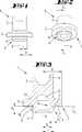
Der Verschlussstopfen
Der Verschlussstopfen
Der Eingriffsabschnitt
An dem Eingriffsabschnitt
Der Dichtvorsprung
Der gepfeilte wie auch der ungepfeilte Dichtflansch
Der Dichtflansch
Beim Ausführungsbeispiel und auch bevorzugt ergibt sich der genannte Durchmesser D1 innerhalb des bzw. in vertikaler Projektion zu dem Rücksprungbereiches Rb.In the exemplary embodiment and also preferably, said diameter D1 results within the or in vertical projection to the return area Rb .
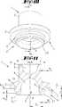
Bei den Ausführungsbeispielen der
Eine der äußeren Grenze des Radialmaßes R1 entsprechende radiale Erstreckung r entspricht bezogen auf den geringsten Abschnittsradius D1 dem 1,05-fachen oder mehr, bis hin bspw. zum 2-fachen.A radial extent r corresponding to the outer limit of the radial dimension R1 corresponds to 1.05 times or more with respect to the smallest segment radius D1, up to, for example, 2 times.
Weiter weist der Dichtvorsprung
Die Schnittpunkte oder Berührungspunkte (im Falle der Tangente), oder ein Schnittpunkt und ein Berührungspunkt, der Konturlinie des Dichtvorsprunges
Beim Ausführungsbeispiel der
Gleiche bzw. sinngemäß gleiche Bezugszeichen (bspw. D1, E2, etc.) bedeuten in allen Ausführungsformen gleiche Elemente, auf welche dann auch grundsätzlich die diesbezüglichen vorstehenden Ausführungen zutreffen.Identical or mutatis mutandis, the same reference numerals (for example, D1, E2, etc.) mean the same elements in all embodiments, which then apply in principle to the relevant above explanations.
Ein Abstand Z zwischen den Vorsprüngen
Es ist auch ersichtlich, dass, wie auch bevorzugt, die Radialmaße R1 bzw. R2 unterschiedlich sind. Darüber hinaus sind auch die Axialmaße Ax1 und Ax2 unterschiedlich. Bevorzugt ist das Radialmaß R2 des unteren Vorsprungs
Diese genannten Unterschiede sind auch bevorzugt signifikant. Jedenfalls im Bereich von 1 bis 20%.These mentioned differences are also preferably significant. In any case, in the range of 1 to 20%.
Beim Ausführungsbeispiel der
Der Dichtvorsprung
Beim Ausführungsbeispiel der
Ein Rücksprungbereich Rb, der sich durch eine Abweichung der Konturlinie L von einer Geraden ergibt, vgl. die Ausführungsformen der
Die maximale radiale Erstreckung der Ausnehmung Rb übertrifft bei diesem Ausführungsbeispiel (wieder) das Maß D1 zuzüglich dem Maß R1.The maximum radial extension of the recess Rb in this embodiment (again) exceeds the dimension D1 plus the dimension R1.
Beim Ausführungsbeispiel der
Die jeweiligen Besonderheiten der einzelnen Ausführungsformen haben nicht nur im Zusammenhang mit der jeweiligen Ausführungsform Bedeutung. So kann das vergleichbar große Axialmaß Ax der Ausführungsformen der
Soweit zwei Vorsprünge
Durch die Ausbildung des Dichtflansches
Alle dargestellten Verschlussstopfen sind bezüglich der Mittelachse A rotationssymmetrisch gebildet.All illustrated plugs are rotationally symmetrical with respect to the central axis A.
Die vorstehend verschiedentlich angegebenen Bereiche relativer oder prozentualer Abmessungen schließen hinsichtlich des Offenbarungsgehaltes auch jeweils sämtliche Zwischenwerte ein, insbesondere in Einzehntel-Schritten, speziell bspw. in Einzehntel-Prozent-Schritten, also einerseits zur Eingrenzung der genannten Bereichsgrenzen von unten und/oder oben, alternativ oder ergänzend aber auch im Hinblick auf die Offenbarung eines oder mehrerer singulärer Werte aus dem jeweiligen Bereich.The areas of relative or percentage dimensions mentioned above also include all intermediate values with regard to the disclosure content, in particular in one-tenth increments, especially, for example, in one-tenths of a percent increments, ie on the one hand to delimit the stated range boundaries from below and / or above, alternatively or additionally but also with regard to the disclosure of one or more singular values from the respective area.
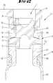
Im Weiteren wird noch angemerkt, dass ersichtlich bei allen Ausführungsformen bevorzugt ist, dass der Verschlussstopfen eine zentrale, von seinem unteren Ende ausgehende erste Höhlung
Die Höhlung
Bevorzugt ist auch, dass die Höhlung
Wie bspw. die Ausführungsform der
Die genannten Höhlungsgestaltungen sind jeweils wiederum nicht auf eine der genannten Ausführungsformen begrenzt. Die Tatsache, dass sie jeweils nur mit einer Ausführungsform konkret kombiniert gezeichnet dargestellt sind, hat nur beispielhaften Charakter. Sie können in gleicher Weise auch bei den anderen Ausführungsformen vorgesehen sein.The aforementioned cavity configurations are in turn not limited to one of the embodiments mentioned. The fact that they are shown in each case specifically combined with only one embodiment drawn in combination, has only exemplary character. They can be provided in the same way in the other embodiments.
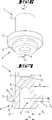
Bezüglich der
Es handelt sich um einen Verschluss
Der Verschluss
Wie sich weiter aus den Querschnittsdarstellungen der
Die Verschlusskappe
Die Rastausformungen
Wie sich weiter aus einem Vergleich der
In den
Alle offenbarten Merkmale sind (für sich) erfindungswesentlich. In die Offenbarung der Anmeldung wird hiermit auch der Offenbarungsinhalt der zugehörigen/beigefügten Prioritätsunterlagen (Abschrift der Voranmeldung) vollinhaltlich mit einbezogen, auch zu dem Zweck, Merkmale dieser Unterlagen in Ansprüche vorliegender Anmeldung mit aufzunehmen. Die Unteransprüche charakterisieren in ihrer fakultativ nebengeordneten Fassung eigenständige erfinderische Weiterbildung des Standes der Technik, insbesondere um auf Basis dieser Ansprüche Teilanmeldungen vorzunehmen.All disclosed features are essential to the invention. The disclosure of the associated / attached priority documents (copy of the prior application) is hereby also incorporated in full in the disclosure of the application, also for the purpose of including features of these documents in claims of the present application. The subclaims characterize in their optional sibling version independent inventive development of the prior art, in particular to make on the basis of these claims divisional applications.
BezugszeichenlisteLIST OF REFERENCE NUMBERS
- 11
- Verschlussstopfensealing plug
- 22
- Handhabungsabschnitthandling section
- 33
- Dichtflanschsealing flange
- 44
- Eingriffsabschnittengaging portion
- 55
- Dichtvorsprungsealing projection
- 66
- Axialabschnittaxial
- 77
- BereichArea
- 88th
- Höhlungcavity
- 99
- Höhlungcavity
- 1010
- Einbuchtungindentation
- 1111
- Verschlussshutter
- 1212
- Ampulleampoule
- 1313
- Verschlusskappecap
- 1414
- Schiebeteilsliding part
- 1515
- Ringteilring part
- 1616
- Rastausformungenlatching recesses
- 1717
- MündungswulstMündungswulst
- 1818
- RastfüßeRest feet
- 1919
- AufsetzfüßeAufsetzfüße
- 2020
- Anbindungconnection
- 2121
- Dichtvorsprung bzw. SchiebevorsSealing projection or Schiebevors
- E1–4E1-4
- Ebenelevel
- E5E5
- Begrenzungsebenelimiting plane
- E6E6
- Ebenelevel
- D1D1
- Abschnittsradiussection radius
- R1R1
- Radialmaßradial
- R2R2
- Radialmaßradial
- RbRb
- RücksprungbereichReturn area
- AxAx
- Axialmaßaxial dimension
- PP
- Paralleleparallel
- AA
- Mittelliniecenter line
- LL
- QuerschnittslinieSection line
- ZZ
- Abstanddistance
- RR
- Erstreckungsmaßextending size
- BB
- Abschnittsection
- rr
- Radialmaßradial
ZITATE ENTHALTEN IN DER BESCHREIBUNG QUOTES INCLUDE IN THE DESCRIPTION
Diese Liste der vom Anmelder aufgeführten Dokumente wurde automatisiert erzeugt und ist ausschließlich zur besseren Information des Lesers aufgenommen. Die Liste ist nicht Bestandteil der deutschen Patent- bzw. Gebrauchsmusteranmeldung. Das DPMA übernimmt keinerlei Haftung für etwaige Fehler oder Auslassungen.This list of the documents listed by the applicant has been generated automatically and is included solely for the better information of the reader. The list is not part of the German patent or utility model application. The DPMA assumes no liability for any errors or omissions.
Zitierte PatentliteraturCited patent literature
- WO 2009/002991 A1[0002]WO 2009/002991 A1[0002]
- WO 2009/051282 A1[0002]WO 2009/051282 A1[0002]
- US 2010/0050575 A1[0002]US 2010/0050575 A1[0002]
- WO 2008/129144 A1[0002]WO 2008/129144 A1[0002]
- CA 2677408 A1[0002]CA 2677408 A1[0002]
- WO 2005/000703 A2[0002]WO 2005/000703 A2[0002]
- US 2002/0113033 A1[0002]US 2002/0113033 A1[0002]
- DE 102004034899 A1[0002]DE 102004034899 A1[0002]
- US 5314084 A[0028]US 5314084A[0028]
Claims (16)
Translated fromGermanPriority Applications (5)
| Application Number | Priority Date | Filing Date | Title |
|---|---|---|---|
| DE102011050983ADE102011050983A1 (en) | 2010-09-09 | 2011-06-09 | Closing plugs for pharmaceutical applications |
| PCT/EP2011/065085WO2012031969A1 (en) | 2010-09-09 | 2011-09-01 | Closure stopper for pharmaceutical uses |
| US13/820,844US10273059B2 (en) | 2010-09-09 | 2011-09-01 | Closure stopper for pharmaceutical applications |
| JP2013527551AJP2013540655A (en) | 2010-09-09 | 2011-09-01 | Medical stopper |
| EP11763616.7AEP2614011B1 (en) | 2010-09-09 | 2011-09-01 | Closure stopper for pharmaceutical uses |
Applications Claiming Priority (3)
| Application Number | Priority Date | Filing Date | Title |
|---|---|---|---|
| DE102010037438 | 2010-09-09 | ||
| DE102010037438.5 | 2010-09-09 | ||
| DE102011050983ADE102011050983A1 (en) | 2010-09-09 | 2011-06-09 | Closing plugs for pharmaceutical applications |
Publications (1)
| Publication Number | Publication Date |
|---|---|
| DE102011050983A1true DE102011050983A1 (en) | 2012-03-15 |
Family
ID=44719870
Family Applications (1)
| Application Number | Title | Priority Date | Filing Date |
|---|---|---|---|
| DE102011050983AWithdrawnDE102011050983A1 (en) | 2010-09-09 | 2011-06-09 | Closing plugs for pharmaceutical applications |
Country Status (5)
| Country | Link |
|---|---|
| US (1) | US10273059B2 (en) |
| EP (1) | EP2614011B1 (en) |
| JP (1) | JP2013540655A (en) |
| DE (1) | DE102011050983A1 (en) |
| WO (1) | WO2012031969A1 (en) |
Families Citing this family (8)
| Publication number | Priority date | Publication date | Assignee | Title |
|---|---|---|---|---|
| USD716656S1 (en)* | 2014-01-15 | 2014-11-04 | Tanio, S.A.U. | Dispenser cap |
| EP3028947A1 (en)* | 2014-12-05 | 2016-06-08 | F. Hoffmann-La Roche AG | Closing a chamber of a container for a pharmaceutical product |
| USD757543S1 (en)* | 2015-01-08 | 2016-05-31 | Runway Blue, Llc | Spout for a container |
| USD778725S1 (en)* | 2015-01-08 | 2017-02-14 | Runway Blue, Llc | Spout for a container |
| US11104489B2 (en)* | 2018-07-13 | 2021-08-31 | Aktiebolaget Skf | Annular seal having a garter spring for establishing a minimum interior diameter and seal plug including the seal |
| EP4217285B1 (en)* | 2020-09-28 | 2025-03-26 | F. Hoffmann-La Roche AG | Closure system and kit |
| AU2021405307A1 (en)* | 2020-12-23 | 2023-06-22 | Daikyo Seiko, Ltd. | Rubber stopper |
| CN114955215B (en)* | 2022-05-27 | 2023-11-28 | 中国航空工业集团公司沈阳飞机设计研究所 | Bottle sealing structure with observable residual capacity scale |
Citations (7)
| Publication number | Priority date | Publication date | Assignee | Title |
|---|---|---|---|---|
| US5314084A (en) | 1992-08-21 | 1994-05-24 | The West Company, Incorporated | Two piece all plastic seal |
| US20020113033A1 (en) | 2000-04-06 | 2002-08-22 | Claessens Albert Louis Victor Jozef | Moulding suitable for pharmaceutical applications and method for production thereof |
| WO2005000703A2 (en) | 2003-06-23 | 2005-01-06 | Helvoet Pharma Belgium N.V. | Closure for lyophilizing |
| DE102004034899A1 (en) | 2004-07-19 | 2005-05-19 | Helvoet Pharma Belgium N.V. | Closure unit for medical containers such as bottles, ampules and the like comprises a component which consists of a thermoplastic elastomer, and is provided with a foil not fully covering its surface |
| WO2008129144A1 (en) | 2007-02-09 | 2008-10-30 | Biocorp Recherche Et Developpement | Device for stopping a container, container equipped with such a device and method for closing a batch of such containers |
| WO2009002991A1 (en) | 2007-06-26 | 2008-12-31 | Praxair Technology, Inc. | Container-closure system for use in lyophilization applications |
| WO2009051282A1 (en) | 2007-10-18 | 2009-04-23 | Daikyo Seiko, Ltd. | Vial rubber-stopper |
Family Cites Families (19)
| Publication number | Priority date | Publication date | Assignee | Title |
|---|---|---|---|---|
| US1634655A (en)* | 1925-01-22 | 1927-07-05 | Huron Mfg Co | Washout plug and method of making same |
| US2663451A (en)* | 1951-10-10 | 1953-12-22 | Chandler P Yarnall | Closure plug |
| US2848130A (en)* | 1953-10-07 | 1958-08-19 | Duo Vent Vacuum Closure Compan | Pressure resistant closures |
| US2927709A (en)* | 1959-07-07 | 1960-03-08 | Faultless Rubber Co | Bottle stopple |
| US3330281A (en)* | 1964-08-21 | 1967-07-11 | Upjohn Co | Combination syringe and vial mixing container |
| BE755165A (en) | 1969-08-23 | 1971-02-22 | Philips Nv | ELASTICALLY DEFORMABLE PLUG FOR INJECTION SYRINGE |
| US3578200A (en)* | 1969-11-03 | 1971-05-11 | Gti Corp | Port protectors |
| US4230231A (en)* | 1979-04-16 | 1980-10-28 | Coulter Electronics, Inc. | Closure cap |
| US4545497A (en)* | 1984-11-16 | 1985-10-08 | Millipore Corporation | Container cap with frangible septum |
| US5680953A (en)* | 1993-11-16 | 1997-10-28 | Rieke Corporation | Plastic drum closure |
| US5862936A (en)* | 1996-09-27 | 1999-01-26 | Sonoco Products & Company | Bung for a pressure vessel |
| US6471082B1 (en)* | 1997-12-17 | 2002-10-29 | Rieke Corporation | Fusible pressure relieving drum closure |
| US20040045967A1 (en)* | 2002-09-11 | 2004-03-11 | Becker Gordon P. | Reclosable metal beverage can |
| ES2310791T3 (en)* | 2004-09-14 | 2009-01-16 | Daikyo Seiko, Ltd. | CONTAINER FOR MEDICINES AND RUBBER CLOSURE. |
| JP5566101B2 (en)* | 2006-04-24 | 2014-08-06 | メディカル・インスティル・テクノロジーズ・インコーポレイテッド | Needle penetrable and laser resealable freeze-drying apparatus and related methods |
| DE102008051351A1 (en)* | 2008-10-10 | 2010-04-15 | Friedrich Sanner Gmbh & Co. Kg | Closure for pressing and locking with a container |
| US8763831B2 (en)* | 2009-12-23 | 2014-07-01 | Daniel L. Garcia | Reuseable bottle cap having identification means |
| DE102010016866B4 (en)* | 2010-05-10 | 2018-06-21 | Helvoet Pharma Belgium N.V. | Closure for a container and method for carrying out a freeze-drying method |
| FR2975976B1 (en)* | 2011-06-06 | 2014-08-29 | Biocorp Rech Et Dev | CLOSURE DEVICE AND CONTAINER EQUIPPED WITH SUCH A DEVICE |
- 2011
- 2011-06-09DEDE102011050983Apatent/DE102011050983A1/ennot_activeWithdrawn
- 2011-09-01USUS13/820,844patent/US10273059B2/enactiveActive
- 2011-09-01WOPCT/EP2011/065085patent/WO2012031969A1/enactiveApplication Filing
- 2011-09-01EPEP11763616.7Apatent/EP2614011B1/enactiveActive
- 2011-09-01JPJP2013527551Apatent/JP2013540655A/ennot_activeWithdrawn
Patent Citations (9)
| Publication number | Priority date | Publication date | Assignee | Title |
|---|---|---|---|---|
| US5314084A (en) | 1992-08-21 | 1994-05-24 | The West Company, Incorporated | Two piece all plastic seal |
| US20020113033A1 (en) | 2000-04-06 | 2002-08-22 | Claessens Albert Louis Victor Jozef | Moulding suitable for pharmaceutical applications and method for production thereof |
| WO2005000703A2 (en) | 2003-06-23 | 2005-01-06 | Helvoet Pharma Belgium N.V. | Closure for lyophilizing |
| DE102004034899A1 (en) | 2004-07-19 | 2005-05-19 | Helvoet Pharma Belgium N.V. | Closure unit for medical containers such as bottles, ampules and the like comprises a component which consists of a thermoplastic elastomer, and is provided with a foil not fully covering its surface |
| WO2008129144A1 (en) | 2007-02-09 | 2008-10-30 | Biocorp Recherche Et Developpement | Device for stopping a container, container equipped with such a device and method for closing a batch of such containers |
| CA2677408A1 (en) | 2007-02-09 | 2008-10-30 | Biocorp Recherche Et Developpement | Device for stopping a container, container equipped with such a device and method for closing a batch of such containers |
| US20100050575A1 (en) | 2007-02-09 | 2010-03-04 | Biocorp Recherche Et Developpement | Device for stopping a container, container equipped with such a device and method for closing a batch of such containers |
| WO2009002991A1 (en) | 2007-06-26 | 2008-12-31 | Praxair Technology, Inc. | Container-closure system for use in lyophilization applications |
| WO2009051282A1 (en) | 2007-10-18 | 2009-04-23 | Daikyo Seiko, Ltd. | Vial rubber-stopper |
Also Published As
| Publication number | Publication date |
|---|---|
| JP2013540655A (en) | 2013-11-07 |
| EP2614011B1 (en) | 2015-08-05 |
| US20130213924A1 (en) | 2013-08-22 |
| EP2614011A1 (en) | 2013-07-17 |
| US10273059B2 (en) | 2019-04-30 |
| WO2012031969A1 (en) | 2012-03-15 |
Similar Documents
| Publication | Publication Date | Title |
|---|---|---|
| EP2614011B1 (en) | Closure stopper for pharmaceutical uses | |
| EP1268301B1 (en) | Screw cap with a brush | |
| EP0786417B1 (en) | Plastic tube presenting a tube body and method of making it | |
| EP3503951B1 (en) | Device for inhaling powdery substances | |
| EP2648784A1 (en) | Syringe cap | |
| EP0312725A2 (en) | Drop dispersing bottle and process for making it | |
| CH715953A2 (en) | Closure cap for closing a container and container with such a captive closure cap. | |
| DE69720396T2 (en) | DISPENSER CAP WITH OUTDOOR DELIVERY OPENING, AND METHOD FOR THE PRODUCTION THEREOF | |
| WO2006053845A1 (en) | Sealing cap | |
| EP2569225B1 (en) | Closure for a receptacle and method for carrying out a freeze-drying process | |
| DE202010005089U1 (en) | Sterile containers for medical purposes | |
| DE202014010527U1 (en) | Lid for a container | |
| DE1164864B (en) | Bottle cap | |
| WO2012168268A1 (en) | Plunger stopper for a lyophilization unit | |
| DE2024385A1 (en) | Container with safety lock | |
| AT525541B1 (en) | Recording device with a septum and method for its production | |
| EP3807163B1 (en) | Process for manufacturing a safety closure, injection moulded part and safety closure | |
| DE20314688U1 (en) | Device for storing and mixing of two or more components has at least two chambers separated from one another and each closed off by membrane, and pin which punctures membrane to allow mixing of components | |
| EP1790582B1 (en) | Tamper evident closure | |
| EP2842883B1 (en) | Cap for a container | |
| AT218894B (en) | Bottle cap | |
| DE1204959B (en) | Closure for liquid container | |
| DE202017104889U1 (en) | Lid for a mixing and dosing tank | |
| DE202008003937U1 (en) | Dosing closure for tubes | |
| WO2012152450A2 (en) | Two-part child-proof lock |
Legal Events
| Date | Code | Title | Description |
|---|---|---|---|
| R119 | Application deemed withdrawn, or ip right lapsed, due to non-payment of renewal fee |