DE102011015780A1 - Small aircraft - Google Patents
Small aircraftDownload PDFInfo
- Publication number
- DE102011015780A1 DE102011015780A1DE102011015780ADE102011015780ADE102011015780A1DE 102011015780 A1DE102011015780 A1DE 102011015780A1DE 102011015780 ADE102011015780 ADE 102011015780ADE 102011015780 ADE102011015780 ADE 102011015780ADE 102011015780 A1DE102011015780 A1DE 102011015780A1
- Authority
- DE
- Germany
- Prior art keywords
- small missile
- jet engine
- fuselage
- missile
- control surfaces
- Prior art date
- Legal status (The legal status is an assumption and is not a legal conclusion. Google has not performed a legal analysis and makes no representation as to the accuracy of the status listed.)
- Ceased
Links
- 238000011144upstream manufacturingMethods0.000claimsdescription2
- 239000007789gasSubstances0.000description8
- 239000000446fuelSubstances0.000description7
- 239000004449solid propellantSubstances0.000description6
- 238000011161developmentMethods0.000description5
- 238000003384imaging methodMethods0.000description5
- 238000013461designMethods0.000description4
- 239000002828fuel tankSubstances0.000description4
- 239000003795chemical substances by applicationSubstances0.000description3
- 239000000463materialSubstances0.000description3
- 238000005259measurementMethods0.000description3
- 230000005540biological transmissionEffects0.000description2
- 230000001276controlling effectEffects0.000description2
- 239000012530fluidSubstances0.000description2
- 231100000518lethalToxicity0.000description2
- 230000001665lethal effectEffects0.000description2
- 239000000779smokeSubstances0.000description2
- 239000000725suspensionSubstances0.000description2
- BUHVIAUBTBOHAG-FOYDDCNASA-N(2r,3r,4s,5r)-2-[6-[[2-(3,5-dimethoxyphenyl)-2-(2-methylphenyl)ethyl]amino]purin-9-yl]-5-(hydroxymethyl)oxolane-3,4-diolChemical compoundCOC1=CC(OC)=CC(C(CNC=2C=3N=CN(C=3N=CN=2)[C@H]2[C@@H]([C@H](O)[C@@H](CO)O2)O)C=2C(=CC=CC=2)C)=C1BUHVIAUBTBOHAG-FOYDDCNASA-N0.000description1
- RZVHIXYEVGDQDX-UHFFFAOYSA-N9,10-anthraquinoneChemical compoundC1=CC=C2C(=O)C3=CC=CC=C3C(=O)C2=C1RZVHIXYEVGDQDX-UHFFFAOYSA-N0.000description1
- 241000272525Anas platyrhynchosSpecies0.000description1
- 239000004743PolypropyleneSubstances0.000description1
- 230000001133accelerationEffects0.000description1
- 230000003044adaptive effectEffects0.000description1
- 230000002411adverseEffects0.000description1
- 238000013459approachMethods0.000description1
- 230000002457bidirectional effectEffects0.000description1
- 238000002144chemical decomposition reactionMethods0.000description1
- 239000002131composite materialSubstances0.000description1
- 238000010276constructionMethods0.000description1
- 230000000694effectsEffects0.000description1
- 238000004146energy storageMethods0.000description1
- 238000005516engineering processMethods0.000description1
- 230000007613environmental effectEffects0.000description1
- 238000004880explosionMethods0.000description1
- 239000002360explosiveSubstances0.000description1
- 239000000835fiberSubstances0.000description1
- 238000010304firingMethods0.000description1
- 238000007667floatingMethods0.000description1
- 239000012774insulation materialSubstances0.000description1
- 239000003350keroseneSubstances0.000description1
- 230000007246mechanismEffects0.000description1
- IMACFCSSMIZSPP-UHFFFAOYSA-Nphenacyl chlorideChemical compoundClCC(=O)C1=CC=CC=C1IMACFCSSMIZSPP-UHFFFAOYSA-N0.000description1
- 239000004033plasticSubstances0.000description1
- -1polypropylenePolymers0.000description1
- 229920001155polypropylenePolymers0.000description1
- 230000002035prolonged effectEffects0.000description1
- 230000001105regulatory effectEffects0.000description1
- 230000035945sensitivityEffects0.000description1
- 230000001953sensory effectEffects0.000description1
- 239000007787solidSubstances0.000description1
- 230000006641stabilisationEffects0.000description1
- 238000011105stabilizationMethods0.000description1
- 239000003491tear gasSubstances0.000description1
- 238000012546transferMethods0.000description1
Images


Classifications
- F—MECHANICAL ENGINEERING; LIGHTING; HEATING; WEAPONS; BLASTING
- F42—AMMUNITION; BLASTING
- F42B—EXPLOSIVE CHARGES, e.g. FOR BLASTING, FIREWORKS, AMMUNITION
- F42B15/00—Self-propelled projectiles or missiles, e.g. rockets; Guided missiles
- F—MECHANICAL ENGINEERING; LIGHTING; HEATING; WEAPONS; BLASTING
- F42—AMMUNITION; BLASTING
- F42B—EXPLOSIVE CHARGES, e.g. FOR BLASTING, FIREWORKS, AMMUNITION
- F42B15/00—Self-propelled projectiles or missiles, e.g. rockets; Guided missiles
- F42B15/01—Arrangements thereon for guidance or control
- F—MECHANICAL ENGINEERING; LIGHTING; HEATING; WEAPONS; BLASTING
- F42—AMMUNITION; BLASTING
- F42B—EXPLOSIVE CHARGES, e.g. FOR BLASTING, FIREWORKS, AMMUNITION
- F42B15/00—Self-propelled projectiles or missiles, e.g. rockets; Guided missiles
- F42B15/10—Missiles having a trajectory only in the air
- F—MECHANICAL ENGINEERING; LIGHTING; HEATING; WEAPONS; BLASTING
- F42—AMMUNITION; BLASTING
- F42B—EXPLOSIVE CHARGES, e.g. FOR BLASTING, FIREWORKS, AMMUNITION
- F42B33/00—Manufacture of ammunition; Dismantling of ammunition; Apparatus therefor
- F42B33/001—Devices or processes for assembling ammunition, cartridges or cartridge elements from parts
Landscapes
- Engineering & Computer Science (AREA)
- General Engineering & Computer Science (AREA)
- Chemical & Material Sciences (AREA)
- Aviation & Aerospace Engineering (AREA)
- Combustion & Propulsion (AREA)
- Manufacturing & Machinery (AREA)
- Aiming, Guidance, Guns With A Light Source, Armor, Camouflage, And Targets (AREA)
- Toys (AREA)
- Control Of Position, Course, Altitude, Or Attitude Of Moving Bodies (AREA)
Abstract
Translated fromGerman
Description
Translated fromGermanTECHNISCHES GEBIETTECHNICAL AREA
Die vorliegende Erfindung betrifft einen Kleinflugkörper mit einem Rumpf und wenigstens zwei Tragflächen sowie einer die Flugbahn lenkenden Steuereinrichtung und einer Antriebseinrichtung nach dem Oberbegriff des Anspruchs 1.The present invention relates to a small missile with a fuselage and at least two wings as well as a control device which directs the trajectory and a drive device according to the preamble of claim 1.
STAND DER TECHNIKSTATE OF THE ART
Ein Einsatzbereich von einem gattungsgemäßen, modularen Kleinflugkörper mit einer Gesamtmasse von beispielsweise bis zu 15 kg, kann etwa darin bestehen, ein Wirkmittel unter hohen Sicherheitsanforderungen mit hoher Geschwindigkeit und hoher Treffergenauigkeit in ein definiertes Ziel zu tragen. Es ist bereits ein Kleinflugkörper bekannt geworden, der ein mit Feststoff betriebenes Raketentriebwerk aufweist. Wenn der Flugkörper auch bei geringer Anströmung steuerbar sein soll, ist es möglich, Strahlruder im Strömungskanal des Feststofftriebwerks vorzusehen. Die hohe thermische Belastung durch das Feststofftriebwerk sorgt aber dafür, dass die Strahlruder innerhalb kürzester Zeit, nämlich wenigen Sekunden, stumpf werden und dadurch der Strömungswiderstand erhöht wird und die Manövrierbarkeit des Flugkörpers beträchtlich verringert wird.A field of application of a generic, modular small missile with a total mass of, for example, up to 15 kg, may be to carry an agent under high security requirements with high speed and high accuracy of hit in a defined target. It is already known a small missile, which has a solid fuel rocket engine. If the missile is to be controllable even at low flow, it is possible to provide thrusters in the flow channel of the solid fuel engine. However, the high thermal load caused by the solids engine ensures that the thrusters within a very short time, namely a few seconds, become dull, thereby increasing the flow resistance and the maneuverability of the missile is considerably reduced.
Anhand der
DARSTELLUNG DER ERFINDUNGPRESENTATION OF THE INVENTION
Ausgehend hiervon liegt der vorliegenden Erfindung die Aufgabe zu Grunde, einen Kleinflugkörper zu schaffen, der die Nachteile eines Feststofftriebwerks vermeidet und mit hoher Geschwindigkeit ins Ziel geführt werden kann und es trotzdem dem Benutzer ermöglicht, die Geschwindigkeit zu verringern, um noch während des Flugs des Kleinflugkörpers in die Mission des Flugs einzugreifen.Based on this, the present invention has the object to provide a small missile, which avoids the disadvantages of a solid propellant and can be performed at high speed to the destination and still allows the user to reduce the speed to even during the flight of the small missile to intervene in the mission of the flight.
Diese Aufgabe wird durch den im Patentanspruch 1 angegebenen Kleinflugkörper gelöst.This object is achieved by the specified in claim 1 small missile.
Der erfindungsgemäße Kleinflugkörper besitzt einen Rumpf und wenigstens zwei Tragflächen sowie eine die Flugbahn lenkende Steuereinrichtung und eine Antriebseinrichtung, wobei die Antriebseinrichtung mindestens ein luftdurchströmtes Strahltriebwerk aufweist und zur Erzeugung von veränderbarem Antriebsschub ausgebildet ist.The small missile according to the invention has a fuselage and at least two wings as well as a control device guiding the trajectory and a drive device, wherein the drive device has at least one jet engine through which air flows and is designed to generate variable drive thrust.
Der Kleinflugkörper weist also mindestens ein von Luft durchströmtes Strahltriebwerk auf, dessen Antriebschub während der Flugphase verändert werden kann. Dadurch besitzt der Benutzer die Möglichkeit, noch während der Flugphase in die Mission einzugreifen, um das Ziel neu zu identifizieren, zu markieren oder in einem Safe-Mode die Mission abzubrechen. Hier ist es von wesentlichem Vorteil, dass der Antriebsschub des erfindungsgemäßen Kleinflugkörpers verändert werden kann, wodurch beispielsweise kurzfristig die Geschwindigkeit des Kleinflugkörpers verringert werden kann, um es dem Benutzer zu ermöglichen, dem Kleinflugkörper im Rahmen eines neuen Einweisvorgangs ein neues Ziel zu übertragen. Gelingt es dem Schützen nicht ein neues Ziel zu erfassen, kann er die Mission in einem Safe-Mode abbrechen.The small missile thus has at least one jet engine through which air flows, the drive thrust of which can be changed during the flight phase. This allows the user to intervene during the flight phase in the mission to re-identify the target, mark or abort the mission in a safe mode. Here it is of substantial advantage that the propulsion thrust of the small missile according to the invention can be changed, whereby, for example, the speed of the small missile can be reduced in the short term to allow the user to transfer the small missile in the context of a new Einweisvorgangs a new destination. If the shooter fails to capture a new target, he can cancel the mission in a safe mode.
Gegenüber einem Propellermodul besitzt das Strahltriebwerk den Vorteil dass der mindestens eine Rotor des Strahltriebwerks durch die Ummantelung geschützt ist. Dadurch wird die Bedienungssicherheit beispielsweise beim Start des erfindungsgemäßen Kleinflugkörpers erhöht.Compared to a propeller module, the jet engine has the advantage that the at least one rotor of the jet engine is protected by the sheathing. As a result, the operating safety is increased, for example, when starting the small missile according to the invention.
Durch die Ummantelung des mindestens einen Rotors werden die infolge von Verwirbelungen an den Blattspitzen des bekannten Propellers bedingten Schubverluste vermieden. Dadurch wird bei gleichem Durchmesser des Rotors wie beim bekannten Propeller ein deutlich höheres Schubniveau erreicht.By sheathing the at least one rotor caused by turbulence at the blade tips of the known propeller shear losses are avoided. As a result, a significantly higher thrust level is achieved with the same diameter of the rotor as in the known propeller.
Im Umkehrschluss ist es möglich, einen kleineren Querschnitt des Rotors vorzusehen, dadurch sinkt der Strömungswiderstand, was wiederum die Fluggeschwindigkeit des Flugkörpers erhöht. Bei dem Strahltriebwerk kann es sich um ein so genanntes COTS Produkt handeln, also um ein am Markt fertig verfügbares Strahltriebwerk, wodurch in vorteilhafter Weise Entwicklungsarbeit für das Triebwerk wegfällt. Ein solches Triebwerk weist üblicherweise aufgrund der daran mit dem Ziel verringerter Eigenmasse bereits geleisteten Entwicklungsarbeit eine niedrige Eigenmasse auf. Variable Reichweiten des erfindungsgemäßen Kleinflugkörpers sind durch einfache Änderungen der mit dem Kleinflugkörper mitgeführten Menge an gespeicherter Antriebsenergie in der Form von beispielsweise Kraftstoff oder elektrischer Energie möglich, ohne dass dies große Änderungen in der Struktur und der Algorithmik des Kleinflugkörpers mit sich bringen würde.Conversely, it is possible to provide a smaller cross section of the rotor, thereby reducing the flow resistance, which in turn increases the flying speed of the missile. The jet engine may be a so-called COTS product, ie a jet engine that is readily available on the market, thereby eliminating development work for the engine in an advantageous manner. Such an engine usually has a low intrinsic mass due to the development work already done with the goal of reduced net mass. Variable ranges of the small missile according to the invention are possible by simple changes in the amount of stored drive energy carried in the form of, for example, fuel or electrical energy with the small missile, without this entailing major changes in the structure and the algorithm of the small missile.
Vorzugsweise ist das Strahltriebwerk elektrisch und/oder brennstoffbetrieben ausgebildet. Wie es vorstehend bereits erwähnt wurde, kann der erfindungsgemäße Kleinflugkörper mehr als eines der genannten Strahltriebwerke aufweisen, so ist es beispielsweise in einer komplexeren Ausbaustufe auch möglich, 4 Antriebe in dem Steuermodul und einen Antrieb im Rumpf zu kombinieren. Dabei können die Antriebe in den Steuermodulen elektrisch sein und der Antrieb im Rumpf brennstoffbetrieben.Preferably, the jet engine is electrically and / or fuel-operated. As already mentioned above, the small missile according to the invention more than one of have mentioned jet engines, so it is also possible, for example, in a more complex stage of development to combine 4 drives in the control module and a drive in the fuselage. The drives in the control modules can be electric and the drive in the fuselage fuel-operated.
Zur Speicherung der Energie kann für das elektrisch betriebene Strahltriebwerk beispielsweise ein handelsüblicher Akkumulator oder eine Brennstoffzelle vorgesehen sein. Ebenso kann für die elektrische Variante auch ein sogenannter Hybrid eingesetzt werden. Ein brennstoffbetriebener Generator oder ein brennstoffbetriebenes Strahltriebwerk mit Generator, speist seine elektrische Energie den Anforderungen gemäß in einen Akkumulator.For storing the energy can be provided for the electrically operated jet engine, for example, a commercial accumulator or a fuel cell. Likewise, for the electrical variant, a so-called hybrid can be used. A fuel-powered generator or a fuel-powered jet engine with generator, feeds its electrical energy according to the requirements in an accumulator.
Während die brennstoffbetriebene Variante einen Tank für Kraftstoff aufweist.While the fuel-powered variant has a tank for fuel.
Die Steuereinrichtung weist vorzugsweise wenigstens drei mittels mindestens eines Aktuators betätigbare Steuerflächen und/oder eine Einrichtung zur Ablenkung von Antriebsschub auf. Auch ist es möglich, einen Kleinflugkörper mit sowohl Steuerflächen als auch einer Einrichtung zur Ablenkung von Antriebsschub vorzusehen.The control device preferably has at least three control surfaces which can be actuated by means of at least one actuator and / or a device for deflecting drive thrust. It is also possible to provide a small missile with both control surfaces and a device for deflecting drive thrust.
Bei den Steuerflächen kann es sich um drehbare oder schwenkbare Auftriebsflächen in der Form sogenannter Finnen handeln, diese sind am Rumpf des Flugkörpers außen angebracht und dienen der Steuerung der Momente für die Regelung der Lage und der Querbeschleunigung. Die Finnen können dabei sowohl als Entensteuerer vor den Tragflächen oder als Hecksteuerer auch hinter den Tragflächen angeordnet sein. Eine Ausführungsform mit beispielsweise vier Finnen hat den Vorteil der Redundanz, so dass der Kleinflugkörper auch bei Ausfall einer der Finnen noch steuerbar bleibt.The control surfaces can be rotatable or pivotable lifting surfaces in the form of so-called fins, which are attached to the fuselage of the missile on the outside and serve to control the moments for regulating the position and the transverse acceleration. The Finns can be arranged as a duck control in front of the wings or as a rear steer behind the wings. An embodiment with, for example, four fins has the advantage of redundancy, so that the small missile remains controllable even if one of the fins fails.
Um den Kleinflugkörper auch noch bei geringer Anströmung steuern zu können, können zusätzliche Steuerflächen vorgesehen sein, die zur lateralen Ablenkung von Antriebsschub dienen, so dass der Kleinflugkörper beispielsweise auch vom Boden aus gestartet werden kann. Diese alternativen oder zusätzlichen Steuerflächen befinden sich im Bereich hinter einer Austrittsöffnung des Strahltriebwerks angeordnet. Die Tatsache, dass es sich bei dem Strahltriebwerk um ein elektrisch betriebenes oder auch ein brennstoffbetriebenes Strahltriebwerk handelt, dessen Austrittsgase entweder nahezu Umgebungstemperatur haben, oder zwar Heißgaskomponenten aufweisen, diese aber eine deutlich niedrigere Temperatur besitzen als die Austrittsgase eines Feststofftriebwerks führt dazu, dass die im Antriebsstrahl des Strahltriebwerks liegenden Steuerflächen einem deutlich geringeren Verschleiß unterliegen als diejenigen, die im Austrittsstrahl eines Feststofftriebwerks angeordnet sind. Damit bleibt der Strömungswiderstand klein und die Manövrierbarkeit des erfindungsgemäßen Kleinflugkörpers bis zum Ziel erhalten.In order to control the small missile even at low flow, additional control surfaces may be provided which serve for the lateral deflection of drive thrust, so that the small missile can be started, for example, from the ground. These alternative or additional control surfaces are located in the area behind an outlet opening of the jet engine. The fact that the jet engine is an electrically driven jet engine or a fuel jet engine whose exhaust gases are either near ambient, or have hot gas components, but have a much lower temperature than the exhaust gases of a solid fuel engine, causes the jet exhaust gases in the Drive jet of the jet engine lying control surfaces subject to significantly lower wear than those which are arranged in the exhaust jet of a solid fuel engine. Thus, the flow resistance remains small and the maneuverability of the small missile according to the invention is maintained to the destination.
Nach der Erfindung ist es vorzugsweise auch vorgesehen, dass die vorstehend erwähnten schublenkenden Steuerflächen mit dem Rumpf des Kleinflugkörpers lösbar verbunden sind und beispielsweise ferngesteuert abgeworfen werden können. Dies ist beispielsweise dann von Vorteil, wenn nach dem Start des Kleinflugkörpers die Luftströmung des Austrittsstrahls des Strahltriebwerks verbessert werden soll und dadurch nach dem Abwerfen der schublenkenden Steuerflächen im Strömungsbereich des Austrittstrahls keine als Drossel wirkenden Fremdkörper mehr vorhanden sind. Die Finnen können dabei über ein System aus Steueraktuatoren gezielt gesteuert werden.According to the invention, it is preferably also provided that the above-mentioned thrust control surfaces are releasably connected to the body of the small missile and can be dropped, for example, remotely controlled. This is for example advantageous if, after the start of the small missile, the air flow of the jet stream of the jet engine is to be improved and thus after the discarding the thrusting control surfaces in the flow region of the outlet jet no foreign body acting as a throttle longer exist. The fins can be selectively controlled via a system of control actuators.
Die Steuerflächen und/oder schublenkenden Steuerflächen können mittels eines Aktuators betätigt werden, wobei es vorzugsweise vorgesehen ist, dass sie paarweise mittels eines jeweiligen Aktuators betätigbar sind. Dies besitzt den Vorteil einer Verringerung der Zahl der zur Steuerung notwendigen Aktuatoren.The control surfaces and / or thrusting control surfaces can be actuated by means of an actuator, wherein it is preferably provided that they can be actuated in pairs by means of a respective actuator. This has the advantage of reducing the number of actuators necessary for the control.
Es ist vorgesehen, dass zur Ablenkung des Antriebsschubs vorzugsweise mindestens ein Strahltriebwerk relativ zum Rumpf bewegbar angeordnet ist und/oder schublenkende Steuerflächen stromabwärts eines Auslasses des Strahltriebwerks angeordnet sind. Das bewegbare Strahltriebwerk kann am Rumpf des Kleinflugkörpers vorzugsweise außen angeordnet und um bis zu zwei Achsen drehbar vorgesehen sein. Zu diesem Zweck kann zur Steuerung der Momente für die Regelung der Lage eine kardanische Aufhängung des Strahltriebwerks vorgesehen sein. Die Bewegung des Strahltriebwerks kann durch zwei Aktuatoren bewerkstelligt werden, dadurch ist eine Steuerbarkeit des Kleinflugkörpers auch ohne Anströmungsgeschwindigkeit in der Nickachse und Gierachse möglich.It is provided that for deflecting the drive thrust preferably at least one jet engine is arranged to be movable relative to the fuselage and / or thrust-reducing control surfaces are arranged downstream of an outlet of the jet engine. The movable jet engine may preferably be arranged on the fuselage of the small missile outside and provided rotatable about up to two axes. For this purpose, a cardanic suspension of the jet engine can be provided to control the moments for the control of the situation. The movement of the jet engine can be accomplished by two actuators, thereby controlling the small missile is possible even without flow velocity in the pitch axis and yaw axis.
Vorzugsweise ist das Strahltriebwerk weitgehend koaxial zur Längsmittelachse des Rumpfes in einem mit mindestens einem Lufteinlasskanal stromaufwärts des Strahltriebwerks versehenen Strömungskanal oder weitgehend parallel zur Längsmittelachse des Rumpfs feststehend oder um mindestens eine Achse drehbar angeordnet. Es bedeutet dies mit anderen Worten, dass das mindestens eine Strahltriebwerk sowohl innerhalb des Rumpfs als auch außerhalb des Rumpfs angeordnet sein kann, wobei bei der Ausführungsform der Anordnung innerhalb des Rumpfes mindestens ein Lufteinlasskanal im Bereich des Rumpfes vorgesehen ist.Preferably, the jet engine is largely coaxial with the longitudinal center axis of the hull in a provided with at least one air inlet duct upstream of the jet engine flow channel or substantially parallel to the longitudinal central axis of the hull fixed or rotatable about at least one axis. In other words, this means that the at least one jet engine can be arranged both inside the fuselage and outside the fuselage, wherein in the embodiment of the arrangement within the fuselage at least one air inlet duct is provided in the region of the fuselage.
Der Lufteinlasskanal besitzt vorzugsweise mindestens einen den Rumpf in Umfangsrichtung zumindest abschnittsweise umgebenden Lufteinlauf, es können also am Rumpf auch mehrere Lufteinläufe vorgesehen sein, die den Rumpf jeweils zumindest abschnittsweise umgeben, also aus der den Rumpf bildenden Umhüllenden zumindest abschnittsweise radial hervortreten und somit eine den Luftstrom aus der Umgebung des Rumpfes dem Einlauf des Strahltriebwerks gesteuert zuführende Öffnung ausbilden. Der Lufteinlauf kann dabei in axialer Längsrichtung des Rumpfes sowohl vor als auch hinter den Tragflächen angeordnet sein, je nachdem, wo in Axiallängsrichtung des Rumpfes das innenliegende Strahltriebwerk angeordnet ist.The air inlet duct preferably has at least one body in the circumferential direction At least partially surrounding air inlet, so it can also be provided on the fuselage several air inlets, which at least partially surround the hull, so at least partially radially emerge from the hull forming sheaths and thus controls the air flow from the environment of the fuselage the inlet of the jet engine train feeding opening. The air inlet can be arranged both in front of and behind the wings in the axial longitudinal direction of the fuselage, depending on where the internal jet engine is arranged in the axial longitudinal direction of the fuselage.
Es ist nach einer Weiterbildung der Erfindung auch vorgesehen, dass ein Auslass des Strömungskanals relativ zur Längsmittelachse des Rumpfes verlagerbar ausgebildet ist. Damit kann ein aus dem Strahltriebwerk austretender Fluidstrom durch den verlagerbaren Auslass zur Steuerung des Kleinflugkörpers abgelenkt werden.It is also provided according to a development of the invention that an outlet of the flow channel is designed to be displaceable relative to the longitudinal center axis of the fuselage. In this way, a fluid flow emerging from the jet engine can be deflected by the displaceable outlet for controlling the small missile.
Es ist nach der Erfindung auch vorzugsweise vorgesehen, dass der Aktuator zur Betätigung von Steuerflächen und/oder schublenkenden Steuerflächen ausgebildet ist. Diese Ausbildung ermöglicht es, dass zur Betätigung von Steuerflächen oder schublenkenden Steuerflächen eine Zahl von Aktuatoren ausreicht, die geringer ist als die Zahl der zu betätigenden Steuerflächen und/oder schublenkenden Steuerflächen.It is also preferably provided according to the invention that the actuator is designed to actuate control surfaces and / or thrust-reducing control surfaces. This design allows a number of actuators sufficient to operate control surfaces or thrusting control surfaces that is less than the number of control surfaces and / or thrust control surfaces to be actuated.
Bei einer Ausführung des Kleinflugkörpers mit mindestens einem am Rumpf außen angeordneten Strahltriebwerk ist es nach der Erfindung auch vorgesehen, dass das Strahltriebwerk mittels eines Aktuators relativ zum Rumpf des Kleinflugkörpers verschwenkbar angeordnet ist. Bei einer Ausführung mit vier außen angeordneten Strahltriebwerken können die Strahltriebwerke auch mit den aerodynamischen Finnen mechanisch gekoppelt werden.In one embodiment of the small missile with at least one jet engine arranged on the outside of the fuselage, according to the invention it is also provided that the jet engine is pivotably arranged relative to the fuselage of the small missile by means of an actuator. In an embodiment with four jet engines arranged on the outside, the jet engines can also be mechanically coupled to the aerodynamic fins.
Schließlich ist es nach der Erfindung auch vorgesehen, dass die mindestens eine Tragfläche am Rumpf vorzugsweise klappbar oder im Rumpf versenkbar angeordnet ist. Diese Ausbildung ermöglicht ist, dass der Kleinflugkörper beispielsweise vom Boden aus dem Stand, oder von einem Fahrzeug aus oder von einem anderen Luftfahrzeug aus, aus einem Startrohr abgeschossen werden kann.Finally, it is also provided according to the invention that the at least one support surface is preferably foldable on the hull or retractable in the hull. This design makes it possible that the small missile can be launched, for example, from the ground out of the stand, or from a vehicle or from another aircraft, from a launch tube.
Eine andere besonders bevorzugte Ausführungsform zeichnet sich dadurch aus, dass die Steuereinrichtung wenigstens drei mittels zumindest eines Aktuators betätigbare Steuerflächen aufweist und dass zumindest ein Strahltriebwerk mechanisch mit den Steuerflächen gekoppelt ist.Another particularly preferred embodiment is characterized in that the control device has at least three actuatable by at least one actuator control surfaces and that at least one jet engine is mechanically coupled to the control surfaces.
Der Kleinflugkörper zeichnet sich also durch einen modularen Aufbau aus.The small missile is thus characterized by a modular design.
Die Modularität zeigt sich darin, dass der Flugkörper aus drei Hauptmodulen, dem Front-End, einer Antriebseinheit und einer Steuereinheit besteht.The modularity is shown in the fact that the missile consists of three main modules, the front end, a drive unit and a control unit.
Im Front-End-Modul befindet sich der Suchkopf, das Gimbalsystem, die IMU, das GPS, der Datenlink, der Videoübertragungssender das Flugführungs-System und das Wirkmittel.In the front-end module is the seeker, the gimbal system, the IMU, the GPS, the data link, the video transmission transmitter the flight guidance system and the agent.
Im Antriebs-Modul befindet sich die Energieversorgung und mindestens eine Antriebseinrichtung angeordnet.In the drive module, the power supply and at least one drive device is arranged.
Im Steuer-Modul befinden sich Servos, zusätzliche Antriebs- und Steuersysteme, die aerodynamischen Steuerflächen und, soweit vorhanden, die Strahlablenkungsmechanismen.The control module includes servos, additional drive and control systems, the aerodynamic control surfaces and, if present, the beam deflection mechanisms.
Die Erfindung vermeidet unter anderem die Nachteile des eingangs beschriebenen Feststofftriebwerks, die nachstehend wiedergegeben sind:
- • eine benötigte sichere Lagerung
- • geringe Lebensdauer infolge des chemischen Zerfalles des Treibstoffes
- • Rauchsignaturen durch Abbrand
- • starke Hitzeentwicklung und die damit einhergehende Belastung auf angrenzende Bauteile
- • schweres und teures Isolationsmaterial
- • viele sicherheitskritischen Aspekte für den Schützen
- • Explosionsgefahr durch Sensitivität gegenüber Stößen
- • ein Startrohr, das den Schützen vor Abgasstrahl schützt
- • Schwierigkeiten beim Verschuss aus geschlossenen Räumen
- • a required safe storage
- • Low life due to chemical decomposition of the fuel
- • Smoke signatures due to burnup
- • strong heat development and the associated stress on adjacent components
- • heavy and expensive insulation material
- • many safety-critical aspects for the shooter
- • Danger of explosion due to sensitivity to impact
- • A launch tube that protects the shooter from the exhaust stream
- • Difficulty in firing indoors
KURZE BESCHREIBUNG DER ZEICHNUNGBRIEF DESCRIPTION OF THE DRAWING
Es zeigen:Show it:
DARSTELLUNG VON BEVORZUGTEN AUSFÜHRUNGSBEISPIELENPRESENTATION OF PREFERRED EMBODIMENTS
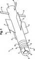
Der in
Wenn nur zwei Tragflächen
Der Werkstoff des gesamten Kleinflugkörpers kann metallische Komponenten, einen Faserverbundwerkstoff, expandiertes Polypropylen oder andere Kunststoffwerkstoffe umfassen. Die Tragflächen
Der vordere Bereich ist das Front-End-Modul
Hinter dem Radom
Der Kleinflugkörper
Hier zahlt sich ein großer Vorteil des erfindungsgemäßen Kleinflugkörpers aus, nämlich der veränderbare Antriebsschub des eingesetzten Strahltriebwerks. Die Zeitdauer nämlich, in der der vorstehend erwähnte Einweisvorgang erfolgen muss, kann durch eine Verringerung des Antriebsschubs des Strahltriebwerks verlängert werden, so dass dem Schützen mehr Zeit für den vorstehend erwähnten Vorgang zur Verfügung steht.Here, a great advantage of the small missile according to the invention pays off, namely the variable drive thrust of the jet engine used. Namely, the time period in which the above-mentioned instructing operation must be performed can be prolonged by a reduction in the driving thrust of the jet engine, so that the shooter has more time available for the above-mentioned operation.
Der Kleinflugkörper
Über ein ebenfalls nicht näher dargestelltes, satellitengestütztes Ortungssystem mit Antenne kann eine Positionsbestimmung erfolgen, um den Kleinflugkörper
Der Kleinflugkörper
Die Daten aller sensorischen Einrichtungen und Informationen aus dem bidirektionalen Datenlink
Die von dem Flugführungs-System
Der Kleinflugkörper
Die in
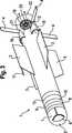
Der in
Das Strahltriebwerk
Durch eine Veränderung des Gehäusequerschnitts können der Druck und die Geschwindigkeit der Strömung an den Bedarf des antreibenden Motors angepasst werden. Die Drehzahl des Motors wird von einem nicht näher dargestellten Drehzahlregler geregelt.By changing the housing cross-section, the pressure and the velocity of the flow can be adapted to the needs of the driving engine. The speed of the motor is controlled by a speed controller, not shown.
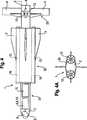
Bei dem in
Die in
Die Steuerung der Momente für die Lageregelung erfolgt bei der in
Die in
Die Steuerflächen
Bei der in
Zu diesem Zweck kann ein flexibler Werkstoff am Endbereich des Rumpfes
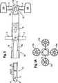
Die in
Eine weitere alternative modulare Ausführungsform des erfindungsgemäßen Kleinflugkörpers ist in
Eine dritte Variante des modularen Aufbaus des erfindungsgemäßen Kleinflugkörpers ist in
Der erfindungsgemäße Kleinflugkörper zeichnet sich durch eine hohe Steuerbarkeit um alle drei Achsen aus. Eine hohe Rollsteuerbarkeit ist insbesondere bei abbildenden Suchköpfen von Bedeutung. Bei einer Ausführungsform des Kleinflugkörpers mit einer Schubvektorsteuerung ist eine hohe Steuerbarkeit auch bei geringer oder ohne Anströmungsgeschwindigkeit möglich. Dadurch wird ein selbstständiger Start vom Boden aus oder ein einfacher Schwebeflug ermöglicht.The small missile according to the invention is characterized by a high controllability around all three axes. High roll controllability is particularly important in imaging seekers of importance. In one embodiment of the small missile with a thrust vector control a high controllability is possible even at low or without flow velocity. This allows a self-sufficient start from the ground or a simple hover.
Die Stabilität eines Flugkörpers gegenüber Störungen hängt in großem Maße davon ab, wie groß die Störkräfte im Verhältnis zu den Steuerkräften sind. Um die Stabilität des Flugkörpers zu erhöhen, kann die Geschwindigkeit erhöht werden, im vorliegenden Fall ermöglichen es das eingesetzte oder die eingesetzten Strahltriebwerke, die Geschwindigkeit gegenüber einem mit Propellerantrieb betriebenen Kleinflugkörper deutlich zu erhöhen, was auch wiederum dadurch ausgenutzt werden kann, die Auftriebsflächen zu verkleinern. Damit wird die von Windkräften beeinflussbare Fläche des Kleinflugkörpers verringert und somit wiederum seine Stabilität erhöht.The stability of a missile to interference largely depends on how great the disturbance forces are in relation to the control forces. In order to increase the stability of the missile, the speed can be increased, in the present case allow the used or used jet engines, the speed compared to a propeller driven small missile to increase significantly, which in turn can be exploited by reducing the lift surfaces , This reduces the influence of wind forces surface of the small missile and thus in turn increases its stability.
Bezugszeichen in den Ansprüchen, der Beschreibung und den Zeichnungen dienen lediglich dem besseren Verständnis der Erfindung und sollen den Schutzumfang nicht einschränken.Reference signs in the claims, the description and the drawings are only for the better understanding of the invention and are not intended to limit the scope.
BezugszeichenlisteLIST OF REFERENCE NUMBERS
- 11
- KleinflugkörperSmall aircraft
- 22
- Rumpfhull
- 33
- Tragflächewing
- 44
- Steuerflächecontrol surface
- 55
- RadomRadom
- 66
- Suchkopfseeker
- 77
- GimbalsystemGimbalsystem
- 88th
- Flugführungs-System und Inertial Measurement Unit und GPSFlight Guidance System and Inertial Measurement Unit and GPS
- 99
- Datenlinkdata link
- 1010
- VideoübertragungssenderVideo transmission stations
- 1111
- StaurohrPitot tube
- 1212
- StrahltriebwerkJet engine
- 12A12A
- StrahltriebwerkJet engine
- 12B12B
- StrahltriebwerkJet engine
- 1313
- Aktuatoractuator
- 1414
- schublenkende Steuerflächesliding control surface
- 1515
- Wirkmitteleffective means
- 1616
- Lufteinlaufair inlet
- 1717
- LufteinlasskanalAir inlet duct
- 1818
- Strömungskanalflow channel
- 1919
- Mantelringcasing ring
- 2020
- Rotorrotor
- 2222
- Auslasskanalexhaust port
- 2323
- Treibstofftank/AkkumulatorFuel tank / accumulator
- 23'23 '
- Treibstofftank/AkkumulatorFuel tank / accumulator
- 2424
- Aufhängungsuspension
- 3131
- Front-End-ModulFront-end module
- 3232
- Antriebsmoduldrive module
- 3333
- Steuermodulcontrol module
ZITATE ENTHALTEN IN DER BESCHREIBUNG QUOTES INCLUDE IN THE DESCRIPTION
Diese Liste der vom Anmelder aufgeführten Dokumente wurde automatisiert erzeugt und ist ausschließlich zur besseren Information des Lesers aufgenommen. Die Liste ist nicht Bestandteil der deutschen Patent- bzw. Gebrauchsmusteranmeldung. Das DPMA übernimmt keinerlei Haftung für etwaige Fehler oder Auslassungen.This list of the documents listed by the applicant has been generated automatically and is included solely for the better information of the reader. The list is not part of the German patent or utility model application. The DPMA assumes no liability for any errors or omissions.
Zitierte PatentliteraturCited patent literature
- DE 102007012799 B3[0003]DE 102007012799 B3[0003]
Claims (14)
Translated fromGermanPriority Applications (3)
| Application Number | Priority Date | Filing Date | Title |
|---|---|---|---|
| DE102011015780ADE102011015780A1 (en) | 2011-04-01 | 2011-04-01 | Small aircraft |
| FR1252930AFR2973499B1 (en) | 2011-04-01 | 2012-03-30 | SMALL FLYING ENGINE |
| GB1205912.7AGB2489611B8 (en) | 2011-04-01 | 2012-04-02 | Small missile |
Applications Claiming Priority (1)
| Application Number | Priority Date | Filing Date | Title |
|---|---|---|---|
| DE102011015780ADE102011015780A1 (en) | 2011-04-01 | 2011-04-01 | Small aircraft |
Publications (1)
| Publication Number | Publication Date |
|---|---|
| DE102011015780A1true DE102011015780A1 (en) | 2012-10-04 |
Family
ID=46160220
Family Applications (1)
| Application Number | Title | Priority Date | Filing Date |
|---|---|---|---|
| DE102011015780ACeasedDE102011015780A1 (en) | 2011-04-01 | 2011-04-01 | Small aircraft |
Country Status (3)
| Country | Link |
|---|---|
| DE (1) | DE102011015780A1 (en) |
| FR (1) | FR2973499B1 (en) |
| GB (1) | GB2489611B8 (en) |
Cited By (2)
| Publication number | Priority date | Publication date | Assignee | Title |
|---|---|---|---|---|
| DE102015012970A1 (en)* | 2015-10-07 | 2017-04-13 | Mbda Deutschland Gmbh | Function-oriented and reconfigurable missile |
| DE102023003108A1 (en)* | 2023-07-28 | 2025-01-30 | BAYERN-CHEMIE Gesellschaft für flugchemische Antriebe mit beschränkter Haftung | TURBINELESS JET ENGINE |
Families Citing this family (3)
| Publication number | Priority date | Publication date | Assignee | Title |
|---|---|---|---|---|
| RU2581097C1 (en)* | 2015-02-19 | 2016-04-10 | Открытое акционерное общество "Научно-производственное объединение "СПЛАВ" | Rocket section with stabilising device of projectile |
| CN112781448A (en)* | 2020-12-29 | 2021-05-11 | 哈尔滨工程大学 | Anti-submarine missile based on water inlet buffer device and control method |
| CN118242941B (en)* | 2024-05-24 | 2024-08-09 | 中科华控航天科技合肥有限公司 | Winding arc type missile wing furling and loading device |
Citations (8)
| Publication number | Priority date | Publication date | Assignee | Title |
|---|---|---|---|---|
| DE1097283B (en)* | 1958-09-16 | 1961-01-12 | Messerschmitt Ag | Manned or unmanned aircraft with jet propulsion for vertical take-off and landing on the stern on unprepared places |
| US3065929A (en)* | 1956-05-15 | 1962-11-27 | Jr Raymond Prunty Holland | Aircraft having aerodynamically tiltable thrust |
| DE2904749C2 (en)* | 1979-02-08 | 1984-01-05 | Messerschmitt-Bölkow-Blohm GmbH, 8000 München | Missile in the manner of a drone |
| DE3643823C2 (en)* | 1986-12-20 | 1988-09-29 | Messerschmitt-Boelkow-Blohm Gmbh, 8012 Ottobrunn, De | |
| DE3829329A1 (en)* | 1987-09-02 | 1989-03-16 | Munoz Saiz Manuel | SUPPORTING DEVICE FOR VERTICAL STARTING AIRCRAFT BASED ON THE DIRECT EFFECT OF THE POWER OF THE ENGINES |
| DE10303189A1 (en)* | 2003-01-27 | 2004-07-29 | Schamuhn, Jörg, Dipl.-Ing. | Propeller for model airplane, has impeller which covers cardan shaft housing in direction parallel to longitudinal axis of airplane, with rotor rotatably mounted in housing, and a drive motor to drive the rotor via a drive shaft |
| DE102007012799B3 (en) | 2007-03-16 | 2008-04-30 | Lfk-Lenkflugkörpersysteme Gmbh | Control device for the production of torques around a longitudinal and transverse axis of a small missile driven over a steering electronics by propellers, comprises wings having an aerodynamic flight stabilization rudder-fin |
| DE102008022289A1 (en)* | 2008-04-25 | 2009-12-10 | Deutsches Zentrum für Luft- und Raumfahrt e.V. | missile |
Family Cites Families (1)
| Publication number | Priority date | Publication date | Assignee | Title |
|---|---|---|---|---|
| US6295932B1 (en)* | 1999-03-15 | 2001-10-02 | Lockheed Martin Corporation | Electronic safe arm and fire device |
- 2011
- 2011-04-01DEDE102011015780Apatent/DE102011015780A1/ennot_activeCeased
- 2012
- 2012-03-30FRFR1252930Apatent/FR2973499B1/enactiveActive
- 2012-04-02GBGB1205912.7Apatent/GB2489611B8/enactiveActive
Patent Citations (8)
| Publication number | Priority date | Publication date | Assignee | Title |
|---|---|---|---|---|
| US3065929A (en)* | 1956-05-15 | 1962-11-27 | Jr Raymond Prunty Holland | Aircraft having aerodynamically tiltable thrust |
| DE1097283B (en)* | 1958-09-16 | 1961-01-12 | Messerschmitt Ag | Manned or unmanned aircraft with jet propulsion for vertical take-off and landing on the stern on unprepared places |
| DE2904749C2 (en)* | 1979-02-08 | 1984-01-05 | Messerschmitt-Bölkow-Blohm GmbH, 8000 München | Missile in the manner of a drone |
| DE3643823C2 (en)* | 1986-12-20 | 1988-09-29 | Messerschmitt-Boelkow-Blohm Gmbh, 8012 Ottobrunn, De | |
| DE3829329A1 (en)* | 1987-09-02 | 1989-03-16 | Munoz Saiz Manuel | SUPPORTING DEVICE FOR VERTICAL STARTING AIRCRAFT BASED ON THE DIRECT EFFECT OF THE POWER OF THE ENGINES |
| DE10303189A1 (en)* | 2003-01-27 | 2004-07-29 | Schamuhn, Jörg, Dipl.-Ing. | Propeller for model airplane, has impeller which covers cardan shaft housing in direction parallel to longitudinal axis of airplane, with rotor rotatably mounted in housing, and a drive motor to drive the rotor via a drive shaft |
| DE102007012799B3 (en) | 2007-03-16 | 2008-04-30 | Lfk-Lenkflugkörpersysteme Gmbh | Control device for the production of torques around a longitudinal and transverse axis of a small missile driven over a steering electronics by propellers, comprises wings having an aerodynamic flight stabilization rudder-fin |
| DE102008022289A1 (en)* | 2008-04-25 | 2009-12-10 | Deutsches Zentrum für Luft- und Raumfahrt e.V. | missile |
Cited By (2)
| Publication number | Priority date | Publication date | Assignee | Title |
|---|---|---|---|---|
| DE102015012970A1 (en)* | 2015-10-07 | 2017-04-13 | Mbda Deutschland Gmbh | Function-oriented and reconfigurable missile |
| DE102023003108A1 (en)* | 2023-07-28 | 2025-01-30 | BAYERN-CHEMIE Gesellschaft für flugchemische Antriebe mit beschränkter Haftung | TURBINELESS JET ENGINE |
Also Published As
| Publication number | Publication date |
|---|---|
| GB2489611B (en) | 2014-11-19 |
| FR2973499A1 (en) | 2012-10-05 |
| GB2489611A (en) | 2012-10-03 |
| GB2489611B8 (en) | 2014-12-03 |
| FR2973499B1 (en) | 2019-05-24 |
| GB201205912D0 (en) | 2012-05-16 |
Similar Documents
| Publication | Publication Date | Title |
|---|---|---|
| EP1674819B1 (en) | Drone | |
| EP3548833B1 (en) | Launching arrangement with a missile for intercepting hostile drones | |
| DE2935044C2 (en) | ||
| DE2904749C2 (en) | Missile in the manner of a drone | |
| DE602004008664T2 (en) | STOREY WITH MULTIPLE NOSE CONE | |
| EP1813907B1 (en) | Missile for the supersonic range | |
| DE102008004054B4 (en) | Unmanned control and monitoring aircraft | |
| DE102011015780A1 (en) | Small aircraft | |
| EP0668829B1 (en) | Flight device | |
| DE102008022289B4 (en) | missile | |
| DE102008014257B4 (en) | Missile | |
| EP4298016B1 (en) | Air vehicle with wing-folding mechanism | |
| IL176804A (en) | Launched object of missile type for observing the ground | |
| DE102010045858B4 (en) | Unmanned small missile | |
| DE202007019067U1 (en) | Propeller-driven aircraft for the performance of tactical tasks | |
| DE102014010109A1 (en) | missile | |
| EP1970664B1 (en) | Control for a miniature aircraft | |
| DE102016101560A1 (en) | Transverse thrust device for active web and attitude control of missiles | |
| DE60302281T2 (en) | Weapon containing a rocket mounted on a stealth plane and weapon system containing a stealth plane and such a weapon | |
| DE10139877A1 (en) | Control system for lighter-than-air craft has at least one turning post-combustion chamber unit with convergent/divergent thrust jets on hull | |
| DE102021000574A1 (en) | multi-body flight system | |
| DE102015014502A1 (en) | Auxiliary airfoil device | |
| DE102022111501B3 (en) | Launch vehicle propulsion stage, Launch vehicle and method of controlling a propulsion stage | |
| DE2815206C2 (en) | Procedure, guided missile and weapon system for combating ground targets | |
| DE102006023827A1 (en) | Thrust-direction turning device of airplane with vertical take-off-landing, and with short-distance take-off-landing, has extension attachment piece, which leads downward during vertical flight |
Legal Events
| Date | Code | Title | Description |
|---|---|---|---|
| R012 | Request for examination validly filed | ||
| R079 | Amendment of ipc main class | Free format text:PREVIOUS MAIN CLASS: F24B0015100000 Ipc:F42B0015100000 | |
| R016 | Response to examination communication | ||
| R081 | Change of applicant/patentee | Owner name:MBDA DEUTSCHLAND GMBH, DE Free format text:FORMER OWNER: LFK-LENKFLUGKOERPERSYSTEME GMBH, 86529 SCHROBENHAUSEN, DE Effective date:20130307 | |
| R002 | Refusal decision in examination/registration proceedings | ||
| R003 | Refusal decision now final | Effective date:20130810 |