Movatterモバイル変換


[0]ホーム

URL:


DE102011013437A1 - Fluid compressor for heat pump, has control unit that is provided to turn off electric motor, when actual drive current of motor exceeds predetermined desired drive current - Google Patents

Fluid compressor for heat pump, has control unit that is provided to turn off electric motor, when actual drive current of motor exceeds predetermined desired drive current
Download PDF

Info

Publication number
DE102011013437A1
DE102011013437A1DE201110013437DE102011013437ADE102011013437A1DE 102011013437 A1DE102011013437 A1DE 102011013437A1DE 201110013437DE201110013437DE 201110013437DE 102011013437 ADE102011013437 ADE 102011013437ADE 102011013437 A1DE102011013437 A1DE 102011013437A1
Authority
DE
Germany
Prior art keywords
drive current
electric motor
actual
unit
temperature
Prior art date
Legal status (The legal status is an assumption and is not a legal conclusion. Google has not performed a legal analysis and makes no representation as to the accuracy of the status listed.)
Ceased
Application number
DE201110013437
Other languages
German (de)
Inventor
Hubert Nolte
Current Assignee (The listed assignees may be inaccurate. Google has not performed a legal analysis and makes no representation or warranty as to the accuracy of the list.)
Stiebel Eltron GmbH and Co KG
Original Assignee
Stiebel Eltron GmbH and Co KG
Priority date (The priority date is an assumption and is not a legal conclusion. Google has not performed a legal analysis and makes no representation as to the accuracy of the date listed.)
Filing date
Publication date
Application filed by Stiebel Eltron GmbH and Co KGfiledCriticalStiebel Eltron GmbH and Co KG
Priority to DE201110013437priorityCriticalpatent/DE102011013437A1/en
Publication of DE102011013437A1publicationCriticalpatent/DE102011013437A1/en
Ceasedlegal-statusCriticalCurrent

Links

Images

Classifications

Landscapes

Abstract

The fluid compressor has an electric motor and a device (1) for monitoring the electric motor. The monitoring device has a measuring unit (10) for measuring an actual drive current of the electric motor and a diagnostic unit (30) for comparing measured actual drive current with a predetermined reference drive current. A control unit (40) is provided to turn off the electric motor, when measured actual drive current exceeds the predetermined desired drive current. Independent claims are included for the following: (1) method for monitoring electric motor of fluid compressor; and (2) heat pump.

Description

Translated fromGerman

Die vorliegende Erfindung betrifft einen Fluidverdichter.The present invention relates to a fluid compressor.

Der Betrieb eines Elektromotors geht mit einer Erwärmung des Motors einher. Diese wird durch den elektrischen Strom hervorgerufen, der im Betrieb durch die Wicklungen des Elektromotors fließt und in diesen neben dem Erzeugen der gewünschten Antriebskraft auch Stromwärmeverluste hervorruft. Ferner kann auch Wärme durch Reibung im Motor entstehen oder von außen, z. B. durch Sonneneinstrahlung oder die Abwärme benachbarter Geräte und Bauteile, in den Elektromotor eingeleitet werden.The operation of an electric motor is accompanied by a heating of the engine. This is caused by the electric current that flows through the windings of the electric motor during operation and also causes current heat losses in addition to generating the desired driving force. Furthermore, heat may also be generated by friction in the engine or from the outside, for. B. by sunlight or the waste heat of adjacent devices and components, are introduced into the electric motor.

Um die Wicklungen eines Elektromotors, insbesondere die Motorwicklung eines Verdichtermotors, vor Überhitzung zu schützen, werden Motorschutzeinrichtungen eingesetzt, die auch als Protektoren oder Motorschutzschalter bezeichnet werden. Ein typischer Anwendungsfall ist die Verwendung thermostatischer Protektoren, die bei längerem Auftreten eines hohen Motorstromes und einer dadurch ausgelösten Erwärmung des Thermostaten den Strompfad des Verdichtermotors unterbrechen und nach Abkühlung des Schaltorgans selbsttätig oder nicht selbsttätig den Strompfad wieder schließen. Typischerweise sind diese Protektoren als Öffner geschaltet.To protect the windings of an electric motor, in particular the motor winding of a compressor motor, from overheating, motor protection devices are used, which are also referred to as protectors or motor protection switch. A typical application is the use of thermostatic protectors that interrupt the current path of the compressor motor with prolonged occurrence of high motor current and thereby triggered heating of the thermostat and after cooling of the switching device automatically or not automatically close the current path again. Typically, these protectors are connected as normally closed.

Die Überhitzung einer Motorwicklung des Elektromotors stellt für diesen eine ernsthafte Gefahr dar, da diese Überhitzung zum Schmelzen der Wicklungsisolierung führen kann. Dies kann einen Kurzschluss zur Folge haben, der den Motor dauerhaft zerstört und auch eine erhebliche Brandgefahr darstellt.The overheating of a motor winding of the electric motor represents a serious danger to this, since this overheating can lead to melting of the winding insulation. This can result in a short circuit that permanently destroys the motor and also poses a significant fire hazard.

Die Wirkungsweise derartiger Motorschutzeinrichtungen beruht i. Allg. auf einer Überwachung der Temperatur des Motors bzw. insbesondere der Wicklungen. Bei der Motorschutzeinrichtung kann es sich dabei um einen Schutzschalter mit einem Bimetall handeln, welches die Überwachung auf thermisch-mechanischem Wege übernimmt. Ferner kann die Überwachung der Temperatur entweder auf thermisch-elektronischem Wege, z. B. mithilfe eines PTC-Transistors, oder auf rein elektronischem Weg, mit einem entsprechenden Messgerät erfolgen.The mode of operation of such motor protection devices is based i. Gen. on a monitoring of the temperature of the motor or in particular of the windings. In the motor protection device may be a circuit breaker with a bimetal, which takes over the monitoring of thermal-mechanical ways. Furthermore, the monitoring of the temperature either thermally-electronic way, for. B. using a PTC transistor, or purely electronic way, with a corresponding meter.

Allen zuvor beschriebenen Motorschutzeinrichtungen ist dabei gemeinsam, dass das Abschalten eines Motors aufgrund einer bereits eingetretenen Überhitzung erfolgt.All motor protection devices described above is common that the shutdown of an engine due to an already occurred overheating occurs.

Der Erfindung liegt daher die Aufgabe zugrunde, eine Möglichkeit zu schaffen, eine Überhitzung der Wicklungen eines Elektromotors eines Fluidverdichters bereits vor ihrem Auftreten zu erkennen und zu verhindern.The invention is therefore based on the object to provide a way to detect overheating of the windings of an electric motor of a fluid compressor already before their occurrence and to prevent.

Die Aufgabe wird durch einen Fluidverdichter nach Anspruch 1, ein Verfahren nach Anspruch 8, eine Vorrichtung zur Überwachung eines Elektromotors nach Anspruch 11 und eine Kompressionskältemaschine oder Wärmepumpe nach Anspruch 12 gelöst.The object is achieved by a fluid compressor according toclaim 1, a method according to claim 8, a device for monitoring an electric motor according to claim 11 and a compression refrigerating machine or heat pump according to claim 12.

Somit wird ein Fluidverdichter K mit einem ersten Elektromotor und einer Vorrichtung zur Überwachung des ersten Elektromotors vorgesehen. Die Vorrichtung zur Überwachung des ersten Elektromotors weist eine Messeinheit zum Messen eines Ist-Antriebsstroms des ersten Elektromotors, eine Diagnoseeinheit zum Vergleichen eines ersten gemessenen Ist-Antriebsstroms mit einem ersten vorgegebenen Soll-Antriebsstroms, und eine Steuerungseinheit zum Ausschalten des ersten Elektromotors auf, wenn der erste gemessene Ist-Antriebsstrom den ersten vorgegebenen Soll-Antriebsstrom überschreitet.Thus, a fluid compressor K is provided with a first electric motor and a device for monitoring the first electric motor. The apparatus for monitoring the first electric motor comprises a measuring unit for measuring an actual driving current of the first electric motor, a diagnosis unit for comparing a first measured actual driving current with a first predetermined target driving current, and a control unit for switching off the first electric motor when first measured actual drive current exceeds the first predetermined target drive current.

Auf diese Weise ist eine Erkennung einer möglichen unzulässigen Erwärmung oder Überhitzung der Wicklungen des Elektromotors bereits vor ihrem Auftreten möglich. So kann der Soll-Wert des Antriebsstroms so gewählt und werkseitig oder auch durch eine Eingabe eines Benutzers vorgegeben werden, dass schon frühzeitig eine Bestromung der Wicklungen, die bei dem Elektromotor zu einer unzulässigen Wärmeentwicklung führen würde, vermieden werden kann. Hierbei kann dieser Soll-Wert des Antriebsstroms auch variabel gestaltet sein. So kann zunächst ein sehr hoher Ist-Wert des Antriebsstroms zulässig sein. Wird dieser jedoch überschritten, kann für folgende Vergleiche zwischen Ist- und Soll-Wert der Soll-Wert dauerhaft oder zeitlich beschränkt heruntergesetzt werden, um zukünftig frühzeitiger einer drohenden Überhitzung entgegenzuwirken. Dabei kann eine derartige zeitliche Veränderung des Soll-Werts des Antriebsstroms auch eine Funktion der bisherigen Überschreitungen des Soll-Werts sein.In this way, it is possible to detect possible inadmissible heating or overheating of the windings of the electric motor even before they occur. Thus, the desired value of the drive current can be selected and specified by the factory or by an input of a user that already early energization of the windings, which would lead to the electric motor to an impermissible heat development, can be avoided. In this case, this desired value of the drive current can also be made variable. Thus, initially a very high actual value of the drive current may be permissible. However, if this value is exceeded, the setpoint value can be reduced permanently or temporarily for the following comparisons between the actual value and the setpoint value, in order to counteract an impending overheating in the future in the future. In this case, such a temporal change of the setpoint value of the drive current can also be a function of the previous exceedances of the setpoint value.

Gemäß einem weiteren Aspekt der Erfindung weist die Vorrichtung einen Aktor zum Trennen des Elektromotors von der Speisung seines Antriebsstroms und bzw. oder eine Auswerteeinheit zum Verarbeiten des gemessenen Ist-Werts des Antriebsstroms auf. Ferner weist die Vorrichtung eine Anzeigeeinheit zum Anzeigen einer Meldung und bzw. oder einer Eingabeeinheit zum Betätigen einer Eingabe auf. Mittels des Aktors erfolgt eine Abschaltung des Elektromotors direkt durch die Vorrichtung selbst, ohne dass hierzu Elemente außerhalb der erfindungsgemäßen Vorrichtung angewiesen werden müssen. Ebenso weist die Vorrichtung selbst eine Auswerteeinheit auf, um die erfassten Werte selbst auswerten zu können. Hierdurch kann auf zusätzliche Elemente verzichtet werden. Ferner kann die Reaktion auf eine Überhitzung und die Auswertung der gemessenen Ist-Werte des Antriebsstroms ohne zeitliche Verzögerung durch die erfindungsgemäße Vorrichtung selbst erfolgen. Die Anzeige- und Eingabeeinheiten dienen der Kommunikation mit dem Benutzer der Vorrichtung.According to a further aspect of the invention, the device has an actuator for disconnecting the electric motor from the supply of its drive current and / or an evaluation unit for processing the measured actual value of the drive current. Furthermore, the device has a display unit for displaying a message and / or an input unit for actuating an input. By means of the actuator is a shutdown of the electric motor directly through the device itself, without requiring elements outside the device according to the invention must be instructed. Likewise, the device itself has an evaluation unit in order to evaluate the detected values themselves. This allows for additional elements be waived. Furthermore, the reaction to overheating and the evaluation of the measured actual values of the drive current can take place without a time delay by the device according to the invention itself. The display and input units are for communication with the user of the device.

Gemäß einem Aspekt der Erfindung veranlasst die Diagnoseeinheit die Steuerungseinheit zum erneuten Einschalten des Elektromotors, falls nach einer vorbestimmten Zeitdauer ein zweiter gemessener Ist-Wert des Antriebsstroms den ersten vorgegebenen Soll-Wert des Antriebsstroms wieder unterschreitet oder ein Benutzer der Vorrichtung eine Eingabe zum erneuten Einschalten des Elektromotors tätigt. Hierdurch wird erreicht, dass der überwachte Elektromotor durch eine einmalige Gefahr der Überhitzung nicht dauerhaft ausgeschaltet wird, sondern der Elektromotor seinen Betrieb durch die erfindungsgemäße Vorrichtung von alleine fortsetzt bzw. der Betrieb wieder aufgenommen wird, falls keine Überhitzung der Wicklungen mehr droht. Auf diese Weise wird auch vermieden, dass der überwachte Elektromotor nicht durch einen Messfehler des Ist-Werts des Antriebsstroms ausgeschaltet wird, sondern die Entscheidung der erfindungsgemäßen Vorrichtung zum Abschalten des Elektromotors stets durch weitere Messungen des Ist-Werts des Antriebsstroms überprüft wird.According to one aspect of the invention, the diagnostic unit causes the control unit to restart the electric motor, if after a predetermined period of time, a second measured actual value of the drive current again falls below the first predetermined target value of the drive current or a user of the device, an input for switching on the Electric motor operates. This ensures that the monitored electric motor is not switched off permanently by a single risk of overheating, but the electric motor continues its operation by the inventive device by itself or the operation is resumed, if no overheating of the windings more threatens. In this way it is also avoided that the monitored electric motor is not turned off by a measurement error of the actual value of the drive current, but the decision of the device according to the invention for switching off the electric motor is always checked by further measurements of the actual value of the drive current.

Gemäß einem weiteren Aspekt der Erfindung veranlasst die Diagnoseeinheit die Steuerungseinheit zum dauerhaften Ausschalten des Elektromotors, falls die Anzahl der Vergleiche der gemessenen Ist-Werte des Antriebsstroms mit dem ersten vorgegebenen Soll-Wert des Antriebsstroms, die zu einem Ausschalten des Elektromotors geführt haben, innerhalb einer vorgegebenen Zeitdauer eine vorgegebene Anzahl, z. B. fünf Überschreitungen, überschreitet und bzw. oder ein gemessener Ist-Wert des Antriebsstroms einen zweiten vorgegebenen Soll-Wert des Antriebsstroms überschreitet. Es wird hierdurch erreicht, dass bei einer Beschädigung des Elektromotors oder der Anlage, in der dieser betrieben wird, nicht dauerhaft durch die erfindungsgemäße Vorrichtung versucht wird, den Elektromotor wieder einzuschalten. Dies könnte zu einer Beschädigung oder Zerstörung des Elektromotors führen. Ferner ist aus den gleichen Gründen ein maximaler Ist-Wert des Antriebsstroms vorzusehen, bei dessen Überschreitung von einem Wiedereinschalten des Elektromotors auf jeden Fall abzusehen ist. Dieser maximale Ist-Wert des Antriebsstroms ist so zu wählen, dass einerseits eine dauerhafte Abschaltung des Elektromotors nicht durch Ist-Werte des Antriebsstroms hervorgerufen wird, die dies überhaupt nicht erforderlich machen, andererseits auch der Elektromotor sicher vor einer Überhitzung geschützt wird, die ihn beschädigen oder zerstören würde.According to a further aspect of the invention, the diagnostic unit causes the control unit to permanently switch off the electric motor, if the number of comparisons of the measured actual values of the drive current with the first predetermined target value of the drive current, which led to a shutdown of the electric motor within a predetermined time a predetermined number, z. B. five transgressions, exceeds and / or a measured actual value of the drive current exceeds a second predetermined desired value of the drive current. It is thereby achieved that in case of damage to the electric motor or the system in which it is operated, is not permanently trying by the inventive device to turn on the electric motor again. This could lead to damage or destruction of the electric motor. Furthermore, for the same reasons, a maximum actual value of the drive current must be provided, beyond which it is to be foreseen that the electric motor will be switched on again. This maximum actual value of the drive current is to be selected such that on the one hand a permanent shutdown of the electric motor is not caused by actual values of the drive current, which do not require this at all, on the other hand, the electric motor is reliably protected from overheating, damaging him or would destroy.

Gemäß einem weiteren Aspekt der Erfindung misst die Messeinheit ferner eine erste Temperatur, eine zweite Temperatur und eine dritte Temperatur. Die Diagnoseeinheit bildet eine Temperaturdifferenz zwischen der ersten Temperatur und der zweiten Temperatur und vergleicht den gemessenen Ist-Wert des Antriebsstroms mit dem ersten vorgegebenen Soll-Wert des Antriebsstroms unter Berücksichtigung der Temperaturdifferenz und der dritten Temperatur. Auf diese Weise kann durch die erfindungsgemäße Vorrichtung eine Beurteilung der Erwärmung der Wicklungen des Elektromotors unter Berücksichtigung einer Temperaturdifferenz z. B. innerhalb eines Kältekreislaufs einer Kompressionskältemaschine oder einer Luft-Brauchwasserwärmepumpe erfolgen. Die Temperaturdifferenz innerhalb eines solchen Kreislaufs entspricht der Leistung, die durch einen Kompressor aufgewendet werden muss, um das Kältemittel zu verdichten. Dies bedeutet, dass je größer die Temperaturdifferenz ist, desto größer sind auch die Kompressionsleistung und damit der Antriebsstrom des Elektromotors des Kompressors. Somit ist auch der zulässige Soll-Wert des Antriebsstroms bei einer höheren Temperaturdifferenz größer als bei einer geringen Temperaturdifferenz. Ferner ist bei einer geringeren, d. h. vergleichsweise kälteren Außentemperatur eine größere Antriebsleistung mit einem entsprechend größeren Ist-Wert des Antriebsstroms hinsichtlich der Erwärmung des Elektromotors vertretbar als bei einer höheren Außentemperatur, die bereits selbst zu einer höheren Erwärmung der Wicklungen des Elektromotors führt.According to another aspect of the invention, the measuring unit further measures a first temperature, a second temperature and a third temperature. The diagnostic unit forms a temperature difference between the first temperature and the second temperature and compares the measured actual value of the drive current with the first predetermined target value of the drive current, taking into account the temperature difference and the third temperature. In this way, by the device according to the invention an assessment of the heating of the windings of the electric motor, taking into account a temperature difference z. B. within a refrigeration cycle of a compression refrigeration machine or an air-fired domestic water heat pump. The temperature difference within such a circuit corresponds to the power that must be expended by a compressor to compress the refrigerant. This means that the greater the temperature difference, the greater the compression power and thus the drive current of the electric motor of the compressor. Thus, the allowable setpoint value of the drive current at a higher temperature difference is greater than at a low temperature difference. Furthermore, at a lower, d. H. comparatively colder outside temperature greater drive power with a correspondingly greater actual value of the drive current with respect to the heating of the electric motor justifiable than at a higher outside temperature, which even leads to a higher heating of the windings of the electric motor.

Gemäß einem Aspekt der Erfindung vergleicht die Diagnoseeinheit die gemessenen Ist-Werte des Antriebsstroms mit einem zeitlichen Verlauf erster vorgegebener Soll-Werte des Antriebsstroms. Auf diese Weise kann beim Anlaufen eines Elektromotors, bei dem z. B. aufgrund der anfänglich größeren Druckdifferenz zwischen Ein- und Ausgang eines Kompressors innerhalb eines Kältekreislaufs einer Kompressionskältemaschine oder einer Luft-Brauchwasserwärmepumpe beim Einschalten eine höhere Leistung als beim laufenden Betrieb erforderlich ist, hinsichtlich einer unzulässigen Erwärmung der Wicklungen überwacht werden. Dabei kann innerhalb der Diagnoseeinheit ein entsprechender zeitlicher Verlauf hinterlegt sein, mit dem für jeden Zeitpunkt des Anlaufens ein Vergleich von Ist-Wert zu Soll-Wert des Antriebsstroms erfolgt. Auch hier ist es möglich, je nach Druckdifferenz innerhalb des Kältekreislaufs einer Kompressionskältemaschine oder einer Luft-Brauchwasserwärmepumpe und bzw. oder der Außentemperatur verschiedene Verläufe der Soll-Werte des Antriebsstroms vorzusehen.According to one aspect of the invention, the diagnostic unit compares the measured actual values of the drive current with a chronological progression of the first predetermined desired values of the drive current. In this way, when starting an electric motor in which z. B. due to the initially greater pressure difference between input and output of a compressor within a refrigeration cycle of a compression refrigeration machine or an air-fired domestic water heat pump when switching a higher power than during operation is required to be monitored with respect to an inadmissible heating of the windings. In this case, a corresponding time profile can be stored within the diagnostic unit, with which a comparison of actual value to nominal value of the drive current takes place for each time of startup. Again, it is possible, depending on the pressure difference within the refrigeration cycle of a compression refrigeration machine or an air-DHW heat pump and / or the outside temperature to provide different curves of the desired values of the drive current.

Gemäß einem Aspekt der Erfindung weist die Messeinheit eine erste Ringspule, die mit einem ersten Elektromotor und einem ersten Kontakt eines Schalters verbunden ist, eine zweite Ringspule, die mit einem zweiten Elektromotor und einem zweiten Kontakt des Schalters verbunden ist, und eine Mikroprozessoreinheit zum Ansteuern des Schalters auf, um zwischen der ersten und zweiten Ringspule umzuschalten. Dabei übergibt die Mikroprozessoreinheit der Messeinheit entweder einen ersten gemessenen Ist-Wert des Antriebsstroms des ersten Elektromotors oder einen zweiten gemessenen Ist-Wert des Antriebsstroms des zweiten Elektromotors über die Auswerteeinheit an die Diagnoseeinheit. Hierdurch kann der Ist-Wert des Antriebsstroms aufgrund einer Messung nach dem Prinzip der Stromzange gemessen werden, ohne dass hierfür weitere Strommessgeräte oder -sensoren benötigt werden.According to one aspect of the invention, the measuring unit has a first annular coil, which is connected to a first electric motor and a first contact of a switch, a second annular coil, the is connected to a second electric motor and a second contact of the switch, and a microprocessor unit for driving the switch to switch between the first and second annular coil. In this case, the microprocessor unit of the measuring unit transfers either a first measured actual value of the drive current of the first electric motor or a second measured actual value of the drive current of the second electric motor via the evaluation unit to the diagnostic unit. As a result, the actual value of the drive current can be measured on the basis of a measurement according to the principle of the current clamp, without the need for further ammeters or sensors.

Die Erfindung betrifft ebenfalls ein Verfahren zur Überwachung eines Elektromotors, welches die o. g. Merkmale der entsprechenden erfindungsgemäßen Vorrichtung nutzt und die entsprechenden Vorteile aufweist.The invention also relates to a method for monitoring an electric motor, which the o. G. Features of the corresponding device according to the invention uses and has the corresponding advantages.

Gemäß einem Aspekt der Erfindung erfolgt bei diesem erfindungsgemäßen Verfahren ein Einschalten eines Lüfters. Es wird das Messen einer Temperatur zwischen den Lamellen eines Verdampfers einer Kältekompressionsmaschine oder Luft-Brauchwasserwärmepumpe als dritte Temperatur durchgeführt. Danach erfolgt ein Einschalten eines Kompressors der Kältekompressionsmaschine oder Luft-Brauchwasserwärmepumpe. Durch diese Schritte kann die Umgebungstemperatur der Kältekompressionsmaschine oder die Lufttemperatur einer Brauchwasserwärmepumpe bestimmt werden, ohne dass hierfür ein separater Temperatursensor benötigt wird. Vielmehr wird die Temperaturmessung zwischen den Lamellen des Verdampfers als Messung der Lufttemperatur dadurch genutzt, dass diese Messung vor dem Einschalten des Kältemittelkreislaufs erfolgt. Diese Temperatur als Lufttemperatur wird dann während des Betriebs des Kältemittelkreislaufs weiterhin als Außentemperatur unterstellt.According to one aspect of the invention, a turning on of a fan takes place in this method according to the invention. It is carried out measuring a temperature between the fins of an evaporator of a refrigeration compressor or air hot water heat pump as a third temperature. Thereafter, switching on a compressor of the refrigeration compressor or air hot water heat pump. Through these steps, the ambient temperature of the refrigeration compressor or the air temperature of a domestic water heat pump can be determined without the need for a separate temperature sensor is required. Rather, the temperature measurement between the fins of the evaporator is used as a measurement of the air temperature, characterized in that this measurement takes place before switching on the refrigerant circuit. This temperature as the air temperature is then assumed during the operation of the refrigerant circuit continues as the outside temperature.

Ausführungsbeispiele und Vorteile der Erfindung werden nachstehend unter Bezugnahme auf folgende Figuren näher erläutert:Exemplary embodiments and advantages of the invention are explained in more detail below with reference to the following figures:

1 zeigt eine schematische Darstellung eines Blockdiagramms einer Kompressionskältemaschine oder einer Wärmepumpe nach dem Stand der Technik, 1 shows a schematic representation of a block diagram of a compression refrigerating machine or a heat pump according to the prior art,

2 zeigt eine schematische Darstellung einer Vorrichtung zur Überwachung eines Elektromotors eines Verdichters gemäß einem ersten Ausführungsbeispiel, 2 shows a schematic representation of an apparatus for monitoring an electric motor of a compressor according to a first embodiment,

3 zeigt eine Darstellung von Verläufen verschiedener Soll-Motorstromwerte ISoll und Ist-Motorstromwerte IIst über einer Temperaturdifferenz ΔT gemäß einem dritten Ausführungsbeispiel, 3 shows a representation of curves of various desired motor current values Isetpoint and actual motor current values Iactual over a temperature difference ΔT according to a third exemplary embodiment,

4 zeigt eine Darstellung von Verläufen eines Soll-Motorstromwerts ISoll und verschiedener Ist-Motorstromwerte IIst über der Zeit t gemäß einem vierten Ausführungsbeispiel, 4 shows a representation of curves of a desired motor current value ISoll and various actual motor current values Iactual over the time t according to a fourth embodiment,

5 zeigt eine schematische Darstellung einer Messeinheit gemäß einem sechsten Ausführungsbeispiel, die zur Verwendung als Messeinheit in einem der vorherigen Ausführungsbeispiele geeignet ist, 5 shows a schematic representation of a measuring unit according to a sixth embodiment, which is suitable for use as a measuring unit in one of the previous embodiments,

6 zeigt eine schematische Darstellung eines Tiefpassfilters, 6 shows a schematic representation of a low-pass filter,

7 zeigt eine schematische Darstellung einer Messeinheit gemäß einem siebten Ausführungsbeispiel, die zur Verwendung als Messeinheit in einem der ersten bis fünften Ausführungsbeispiele geeignet ist, und 7 shows a schematic representation of a measuring unit according to a seventh embodiment, which is suitable for use as a measuring unit in one of the first to fifth embodiments, and

8 zeigt eine schematische Darstellung einer Messeinheit gemäß einem achten Ausführungsbeispiel, die zur Verwendung als Messeinheit in einem der ersten bis fünften Ausführungsbeispiele geeignet ist. 8th shows a schematic representation of a measuring unit according to an eighth embodiment, which is suitable for use as a measuring unit in one of the first to fifth embodiments.

1 zeigt eine schematische Darstellung eines Blockdiagramms einer Kompressionskältemaschine oder einer Wärmepumpe nach dem Stand der Technik. Die Kompressionskältemaschine oder Wärmepumpe weist dabei einen Enthitzer E, einen Verdampfer V, ein erstes Drosselorgan D1 (Drosselventil) und einen Regler R auf. Optional kann die Wärmepumpe ein Filter F zwischen dem ersten Drosselorgan D1 und dem Enthitzer E aufweisen. Zwischen dem Verdampfer V und dem Enthitzer E ist ein Verdichter bzw. ein Kompressor K vorgesehen. Zwischen dem Verdichter K und dem ersten Drosselorgan D1 befindet sich die Hochdruckseite des Kreislaufs. Der Druck hinter dem Verdichter K beträgt beispielsweise 80 bar. Im Kreislauf befindet sich ein Kältemittel. 1 shows a schematic representation of a block diagram of a compression refrigerating machine or a heat pump according to the prior art. The compression refrigeration machine or heat pump in this case has a desuperheater E, an evaporator V, a first throttle element D1 (throttle valve) and a regulator R. Optionally, the heat pump may have a filter F between the first throttle D1 and the desuperheater E. Between the evaporator V and the desuperheater E, a compressor or a compressor K is provided. Between the compressor K and the first throttle D1 is the high pressure side of the circuit. The pressure behind the compressor K is for example 80 bar. There is a refrigerant in the circuit.

Ferner weist der Kreislauf ein Ventil C (Checkventil) auf, welches ein Rückströmen des Kältemittels in den Kompressor K während der Bereitschaftsdauer verhindert. Auch weist der Kreislauf eine Heißgasstrecke HG, ein Magnetventil VHS und ein zweites Drosselorgan D2 (Drosselkapillare) auf.Furthermore, the circuit has a valve C (check valve), which prevents a return flow of the refrigerant into the compressor K during the standby period. The circuit also has a hot gas line HG, a magnetic valve VHS and a second throttle element D2 (throttle capillary).

Die Enthitzer E (Kondensator, Verflüssiger) gibt dabei Wärme an die Umgebung ab und der Verdampfer V nimmt Wärme aus der Umgebung auf. Dabei wird der Kältemitteldampf vom Kompressor K unter Aufwendung einer Antriebsenergie angesaugt und verdichtet. In dem nachgeschalteten Enthitzer E kondensiert das Kältemittel unter Abgabe einer Wärmeenergiemenge an die Umgebung bzw. an das Brauchwasser. Im ersten Drosselorgan D1 entspannt sich das Kältemittel, d. h. der Druck nimmt ab. In dem Verdampfer V nimmt das Kältemittel durch Verdampfen eine Kühlleistung bzw. Verdampfungswärme aus dem Kühlraum bzw. der Umgebung auf. Der Kompressor K saugt das verdampfte Kältemittel wieder an und der Kreisprozess ist geschlossen.The desuperheater E (condenser, condenser) releases heat to the environment and the evaporator V absorbs heat from the environment. In this case, the refrigerant vapor is sucked in by the compressor K using a drive energy and compressed. In the downstream desuperheater E, the refrigerant condenses while releasing a quantity of thermal energy to the environment or to the process water. In the first throttle D1 , the refrigerant expands, ie, the pressure decreases. By doing Evaporator V takes the refrigerant by evaporation, a cooling power or heat of vaporization from the refrigerator or the environment. The compressor K sucks in the vaporized refrigerant again and the cycle is closed.

Während eines Abtauvorgangs wird das Heißgas vom Kompressor K unter Umgehung des Verflüssigers E über das geöffnete Magnetventil VHG und das zweite Drosselorgan D2 direkt dem Verdampfer V zugeführt. Das Magnetventil VHG wird wieder geschlossen, sobald der Abtauvorgang beendet ist. Das zweite Drosselorgan D2 sorgt dafür, dass eine Kondensation im Verdampfer V verhindert wird. Während des Abtauvorgangs wird das Drosselorgan D1 vom Regler R in die Stellung „zu” gefahren.During a defrosting operation, the hot gas from the compressor K, bypassing the condenser E via the open solenoid valve VHG and the second throttle D2 is fed directly to the evaporator V. The solenoid valve VHG is closed again as soon as the defrosting process is completed. The second throttle D2 ensures that condensation in the evaporator V is prevented. During defrosting the throttle D1 is moved by the controller R in the "closed" position.

2 zeigt eine schematische Darstellung einer Vorrichtung1 zur Überwachung eines Elektromotors eines Verdichters gemäß einem ersten Ausführungsbeispiel. Als Beispiel eines zu überwachenden Elektromotors wird in dem ersten Ausführungsbeispiel der Elektromotor des Kompressors K einer Kompressionskältemaschine nach1 betrachtet. 2 shows a schematic representation of adevice 1 for monitoring an electric motor of a compressor according to a first embodiment. As an example of an electric motor to be monitored, in the first exemplary embodiment, the electric motor of the compressor K of a compression refrigerating machine is after 1 considered.

Die Vorrichtung1 weist eine Messeinheit10, eine Auswerteeinheit20, eine Diagnoseeinheit30, eine Steuerungseinheit40 und eine Anzeigeeinheit50 auf. Die Messeinheit10 erhält eine Anzahl n von Messwerten MW1 bis MWn, welches beispielsweise Stromwerte sein können. Dabei können die Messwerte MW1 bis MWn durch die Messeinheit10 selbst oder teilweise oder vollständig durch Sensoren (nicht dargestellt), die mit der Messeinheit10 verbunden sind, erfasst und an die Messeinheit10 übergeben werden. Die Ermittlung der Messwerte MW1 bis MWn erfolgt im Betrieb des zu überwachenden Elektromotors regelmäßig, z. B. pro Sekunde ein Mal. Aufgrund einer derart niederfrequenten Messung der Messwerte MW1 bis MWn kann auf hochfrequente Messwertaufnehmer verzichtet werden, die teurer sind als einfachere und niederfrequent arbeitende Messwertaufnehmer, die für diesen Anwendungsfall vollkommen ausreichen.Thedevice 1 has a measuringunit 10 , anevaluation unit 20 , adiagnostic unit 30 , acontrol unit 40 and adisplay unit 50 on. The measuringunit 10 receives a number n of measured values MW1 to MWn, which may be, for example, current values. In this case, the measured values MW1 to MWn can be determined by the measuringunit 10 itself or partially or completely by sensors (not shown) connected to the measuringunit 10 are connected, detected and sent to the measuringunit 10 be handed over. The determination of the measured values MW1 to MWn takes place during operation of the electric motor to be monitored regularly, z. For example, once a second. Due to such a low-frequency measurement of the measured values MW1 to MWn, it is possible to dispense with high-frequency transducers which are more expensive than simpler and low-frequency transducers which are completely adequate for this application.

Die Messeinheit10 ist mit der Auswerteeinheit20 verbunden, welche die Messwerte MW1 bis MWn von der Messeinheit10 erhält. Dabei können die Messwerte MW1 bis MWn durch die Messeinheit10 vor der Weiterleitung an die Auswerteeinheit20 weiterverarbeitet worden sein, z. B. durch eine Signalfilterung und bzw. oder eine Analog-Digital-Wandlung oder eine Digital-Analog-Wandlung, oder sie werden direkt so weitergeleitet, wie sie von der Messeinheit10 gemessen oder erhalten wurden.The measuringunit 10 is with theevaluation unit 20 connected, which the measured values MW1 to MWn from the measuringunit 10 receives. In this case, the measured values MW1 to MWn can be determined by the measuringunit 10 before forwarding to theevaluation unit 20 be further processed, for. Example, by a signal filtering and or or an analog-to-digital conversion or a digital-to-analog conversion, or they are forwarded directly as they are from the measuringunit 10 measured or obtained.

Die Auswerteeinheit20 führt eine Auswertung der erhaltenen Messwerte MW1 bis MWn durch und übergibt das Ergebnis dieser Auswertung an die Diagnoseeinheit30. Die Diagnoseeinheit30 führt einen Vergleich der Messwerte MW1 bis MWn mit gespeicherten Referenzwerten bzw. Sollwerten durch. Auch kann ein Ergebnis eines Vergleichs der Diagnoseeinheit30 ebenfalls Gegenstand eines weiteren Vergleichs mit anderen Vergleichsergebnissen, mit einem oder mehreren Messwerten MW1 bis MWn sein. Dabei werden diese Vergleiche und Auswertungen ebenfalls regelmäßig im Betrieb des zu überwachenden Elektromotors durchgeführt, z. B. pro Sekunde ein Mal.Theevaluation unit 20 performs an evaluation of the obtained measured values MW1 to MWn and transfers the result of this evaluation to thediagnostic unit 30 , Thediagnostic unit 30 performs a comparison of the measured values MW1 to MWn with stored reference values or nominal values. Also, a result of a comparison of thediagnostic unit 30 also be the subject of a further comparison with other comparison results, with one or more measured values MW1 to MWn. These comparisons and evaluations are also carried out regularly in the operation of the monitored electric motor, z. For example, once a second.

Die Diagnoseeinheit30 ist mit der Steuerungseinheit40 verbunden, die ein erstes Relais41 und ein zweites Relais42 ansteuert. Ferner ist die Diagnoseeinheit30 mit einer Anzeigeeinheit50 verbunden, mittels der Meldungen an den Benutzer ausgegeben werden können, um z. B. auf eine Störung hinzuweisen oder Mess- oder Vergleichsergebnisse anzuzeigen. Diese Meldungen können ein optisches Signal auf einer Anzeige der Anzeigeeinheit50 sein, welches stehend oder auch blinkend ausgegeben wird, um hierdurch die Aufmerksamkeit des Benutzers zu erregen. Die Meldung kann auch ein akustisches Signal sein, welches als dauerhaftes, unterbrochenes oder sich wiederholendes Signal ausgegeben werden kann. Neben diesen Meldungen, die durch eine Erwärmung der Wicklungen des Motors hervorgerufen werden, können auch weitere Informationen dem Benutzer angezeigt werden, wie z. B. der Energieverbrauch des Systems, sowohl absolut als auch relativ zu einem Vergleichssystem. Diese Meldungen können vom Benutzer über einen Resetschalter, -taster oder -knopf51 bestätigt werden. Ein solches Bestätigen wird von der Anzeigeeinheit50 an die Diagnoseeinheit30 weitergeleitet.Thediagnostic unit 30 is with thecontrol unit 40 connected, which is afirst relay 41 and asecond relay 42 controls. Furthermore, thediagnostic unit 30 with adisplay unit 50 connected, can be output by means of messages to the user to z. B. to indicate a fault or display measurement or comparison results. These messages can be an optical signal on a display of thedisplay unit 50 which is issued standing or flashing, thereby attracting the user's attention. The message can also be an acoustic signal that can be output as a permanent, interrupted or repeating signal. In addition to these messages, which are caused by a heating of the windings of the motor, other information can be displayed to the user, such. For example, the power consumption of the system is both absolute and relative to a comparison system. These messages can be provided by the user via a reset switch, pushbutton orbutton 51 beeing confirmed. Such confirmation is made by thedisplay unit 50 to thediagnostic unit 30 forwarded.

In dem ersten Ausführungsbeispiel wird durch die Messeinheit10 der Ist-Motorstromwert IIst als Messwert MW1 gemessen. Der Messwert MW1 wird über die Auswerteeinheit20 der Diagnoseeinheit30 als Ist-Motorstromwert IIst übergeben. Die Diagnoseeinheit30 vergleicht den gemessenen Ist-Motorstromwert IIst mit einem in der Diagnoseeinheit30 vorgegebenen Soll-Motorstromwert ISoll und wertet diesen Vergleich aus.In the first embodiment is by the measuringunit 10 the actual motor current value Iis measured as measured value MW1. The measured value MW1 is sent via theevaluation unit 20 thediagnostic unit 30 as actual motor current value IIst transferred. Thediagnostic unit 30 compares the measured actual motor current value IIst with one in thediagnostic unit 30 predetermined setpoint motor current value Isetpoint and evaluates this comparison.

Ergibt der Vergleich, dass der Ist-Motorstromwert IIst kleiner ist als der Soll-Motorstromwert ISoll wird der Ist-Motorstromwert IIst von der Diagnoseeinheit30 als innerhalb normaler Belastungsgrenzen liegend bewertet, d. h. der Motor läuft in einem normalen Betrieb und es liegt keine Überlastung vor. Damit wird auch die Erwärmung des Motors als normal, d. h. zulässig, angesehen und der Betrieb des Motors und damit der Kompressionskältemaschine kann fortgesetzt werden. Eine entsprechende Meldung kann von der Diagnoseeinheit30 mittels der Anzeigeeinheit50 an den Benutzer ausgegeben werden. Auch ist es möglich, dass eine derartige Meldung zusätzlich oder ausschließlich an eine oder mehrere Vorrichtungen ausgegeben werden, die mit der Diagnoseeinheit30 verbunden sind.If the comparison shows that the actual motor current value Iactual is smaller than the setpoint motor current value Isetpoint , the actual motor current value Iactual is obtained from thediagnostic unit 30 rated as within normal load limits, ie the engine is running normally and there is no overload. Thus, the heating of the engine is considered normal, ie permissible, and the operation of the engine and thus the compression refrigeration machine can be continued. A corresponding message can be sent from thediagnostic unit 30 by means of thedisplay unit 50 be issued to the user. It is also possible that such a message additionally or exclusively to one or more devices be issued with thediagnostic unit 30 are connected.

Ergibt der Vergleich von Ist-Motorstromwert IIst und Soll-Motorstromwert ISoll, dass der Ist-Motorstromwert IIst den Soll-Motorstromwert ISoll überschreitet, wird dies von der Diagnoseeinheit30 als das Auftreten eines unzulässigen Betriebszustandes gewertet. Aus dieser Überschreitung wird geschlossen, dass durch den unzulässig erhöhten Ist-Motorstromwert IIst auch eine entsprechende unzulässige Erwärmung der Wicklungen des Motors bereits hervorgerufen wird oder in Zukunft hervorgerufen werden kann. Dabei kann diese Schlussfolgerung bereits aus einem einmaligen Überschreiten des Soll-Motorstromwerts ISoll gefolgert werden oder es können auch mehrere Überschreitungen, insgesamt oder innerhalb einer bestimmten Zeitspanne, in der Diagnoseeinheit30 als Kriterium für eine mögliche unzulässige Erwärmung der Wicklungen des Motors vorgegeben sein. Auch kann die Zeitspanne, innerhalb derer Überschreitungen als unzulässig gewertet werden, mit der Anzahl der Überschreitungen ansteigen, wobei die Anzahl der Überschreitungen durch die Diagnoseeinheit30 bestimmt und gespeichert wird. Ferner kann neben einem ersten Soll-Motorstromwert ISoll, der einmalig oder regelmäßig mehrfach überschritten werden darf, auch ein zweiter maximaler Soll-Motorstromwert Isoll,max in der Diagnoseeinheit30 vorgesehen sein, der auf jeden Fall nur einmalig überschritten werden darf.If the comparison of the actual motor current value Iactual and the target motor current value Iset shows that the actual motor current value Iactual exceeds the setpoint motor current value Isetpoint , this is determined by thediagnostic unit 30 considered the occurrence of an impermissible operating state. From this excess, it is concluded that due to the impermissibly increased actual motor current value Iactual , a corresponding impermissible heating of the windings of the motor is already caused or can be caused in the future. In this case, this conclusion can already be inferred from a one-time exceeding of the setpoint motor current value Isetpoint , or it can also be several overshoots, in total or within a certain period of time, in thediagnostic unit 30 be given as a criterion for a possible impermissible heating of the windings of the motor. Also, the time period within which transgressions are considered inadmissible increase with the number of transgressions, wherein the number of transgressions by thediagnostic unit 30 is determined and stored. Furthermore, in addition to a first nominal motor current value Isetpoint , which may be exceeded once or regularly several times, a second maximum setpoint motor current value I setpoint, max in the diagnostic unit may also be used 30 be provided, which may be exceeded in any case only once.

Die Diagnoseeinheit30 gibt in diesem Fall eine Meldung über die Anzeigeeinheit50 an den Benutzer und bzw. oder an weitere angeschlossene Vorrichtungen aus. Ferner wird von der Diagnoseeinheit30 an die Steuerungseinheit40 eine Meldung ausgegeben, dass eine unzulässige Erwärmung der Wicklungen des Motors vorliegt. Die Steuerungseinheit40 öffnet dann ein entsprechendes Relais41, um die Stromzufuhr zu den Wicklungen des Motors zu unterbrechen. Auf diese Weise wird verhindert, dass durch eine weitere Bestromung der Wicklungen des Motors die Überhitzung der Wicklungen weiter zunimmt und eine Erwärmung erreicht wird, durch die der Motor beschädigt oder zerstört werden würde.Thediagnostic unit 30 in this case gives a message about thedisplay unit 50 to the user and / or to other connected devices. Further, thediagnosis unit 30 to the control unit 40 a message is issued that there is an inadmissible heating of the windings of the motor. Thecontrol unit 40 then opens acorresponding relay 41 to interrupt the power supply to the windings of the motor. In this way prevents further energization of the windings of the motor, the overheating of the windings continues to increase and a warming is achieved, through which the engine would be damaged or destroyed.

Die Trennung der Wicklungen des Motors von der Stromzufuhr schützt zwar zum einen den Motor vor einer zunehmenden unzulässigen Erwärmung, jedoch wird hierdurch auch die Funktion des Motors, in diesem ersten Ausführungsbeispiel die Kompression des Kältemittels durch den Kompressor K, unterbrochen. Daher ist es erforderlich, dass dieser Zustand wieder verlassen und die Funktion wiederaufgenommen wird, sobald die Gefahr der Überhitzung der Wicklungen des Motors nicht mehr besteht.Although the separation of the windings of the motor from the power supply protects on the one hand the engine from increasing inadmissible heating, but this also the function of the engine, in this first embodiment, the compression of the refrigerant by the compressor K, interrupted. It is therefore necessary to leave this state again and to resume the function as soon as the risk of overheating of the windings of the motor no longer exists.

Dies kann durch die Vorrichtung1 mittels der Diagnoseeinheit30 selbst geschehen, indem nach dem Verstreichen einer vorgegebenen Zeitspanne die Diagnoseeinheit30 die Steuerungseinheit40 anweist, das Relais41 wieder zu schließen und damit den Motor wieder mit Strom zu versorgen. Hierdurch wird der Betrieb des Kompressors K wieder aufgenommen. Diese Wiederaufnahme des Betriebs ist jedoch nicht möglich, falls der maximale Soll-Motorstromwert ISoll,max überschritten wurde.This can be done by thedevice 1 by means of thediagnostic unit 30 itself done by the diagnostic unit after lapse of a predetermined period oftime 30 thecontrol unit 40 instructs therelay 41 close again and thus supply the engine with electricity again. As a result, the operation of the compressor K is resumed. However, this resumption of operation is not possible if the maximum setpoint motor current value ISoll, max has been exceeded.

Alternativ oder zusätzlich kann der Betrieb des Kompressors K auch dadurch wieder aufgenommen werden, dass die Meldung der Anzeigeeinheit50 an den Benutzer, dass eine unzulässige Erwärmung vorliegt und der Kompressor K durch die Vorrichtung1 selbst ausgeschaltet wurde, vom Benutzer durch den Resetschalter51 bestätigt wird. In diesem Fall wird die Steuerungseinheit40 von der Diagnoseeinheit30 angewiesen, sofort das Relais41 wieder zu schließen und dadurch den Motor des Kompressors K einzuschalten.Alternatively or additionally, the operation of the compressor K can also be resumed by the fact that the message of thedisplay unit 50 to the user that there is an improper heating and the compressor K through thedevice 1 even turned off by the user through thereset switch 51 is confirmed. In this case, thecontrol unit 40 from thediagnostic unit 30 instructed, immediately therelay 41 close again and thereby turn on the engine of the compressor K.

Eine Wiederaufnahme des Betriebs ausschließlich nach der Bestätigung der Meldung durch den Benutzer ist dann sinnvoll, falls die Abschaltung aufgrund einer Überschreitung des maximalen Soll-Motorstromwerts ISoll,max erfolgte, da in diesem Fall von einer ernsthaften Störung, z. B. durch die Beschädigung einer Komponente der Kompressionskältemaschine, ausgegangen werden muss, die nur durch das Eingreifen des Benutzers behoben werden kann. Auch kann es in diesem Fall sinnvoll sein, zum Schutz der Kompressionskältemaschine eine Bestätigung der Meldung durch den Benutzer und damit eine Wiederaufnahme des Betriebs vollkommen auszuschließen, um sicherzustellen, dass eine beschädigte Kompressionskältemaschine nicht weiterbetrieben und dadurch weiter beschädigt oder vollkommen zerstört wird. In diesem Fall kann eine Wiederaufnahme des Betriebs nur durch einen Service-Techniker möglich sein, nachdem dieser die Kompressionskältemaschine untersucht und gegebenenfalls die Beschädigung behoben hat.A resumption of operation only after confirmation of the message by the user is useful if the shutdown was due to exceeding the maximum target motor current value Itarget, max , since in this case a serious fault, z. B. by damaging a component of the compression chiller, must be assumed that can only be resolved by the intervention of the user. It may also be useful in this case, for the protection of the compression refrigeration machine to completely exclude a confirmation of the message by the user and thus resumption of operation to ensure that a damaged compression refrigeration machine is not continued and thereby further damaged or completely destroyed. In this case, resumption of operation may only be possible by a service technician after inspecting the compression refrigeration unit and, if necessary, repairing the damage.

In einem zweiten Ausführungsbeispiel wird als zweiter Messwert MW2 die Temperatur TLamelle zwischen den Lamellen L des Verdampfers bzw. am Rohr des Verdampfers durch die Messeinheit10 bestimmt und mittels der Auswerteeinheit20 der Diagnoseeinheit30 übermittelt. Die Diagnoseeinheit30 vergleicht die Temperatur TLamelle mit einer Mindesttemperatur TLamelle..min, die einer Grenze entspricht, bei der der Bedarf für einen Abtauvorgang der Wärmepumpe erkannt wird, z. B. –7°C. Wird die Mindesttemperatur TLamelle..min unterschritten, leitet die Diagnoseeinheit30 einen Abtauvorgang ein.In a second exemplary embodiment, the second measured value MW2 is the temperature Tlamella between the lamellae L of the evaporator or, at the tube of the evaporator, through the measuringunit 10 determined and by means of theevaluation unit 20 thediagnostic unit 30 transmitted. Thediagnostic unit 30 compares the temperature Tlamella with a minimum temperature Tlamella..min , which corresponds to a limit at which the need for a defrosting process of the heat pump is detected, for. Eg -7 ° C. If the minimum temperature Tlamella..min is undershot, the diagnosticsunit will be triggered 30 a defrosting process.

Dies kann in Form einer Luftabtauung dadurch geschehen, dass über die Steuerungseinheit40 durch Öffnen des Relais41 der Kompressor K solange ausgeschaltet wird, bis die gemessene Temperatur TLamelle die Mindesttemperatur TLamelle..min wieder um einen vorgegeben Betrag überschritten hat. Hierbei bleibt der Motor der Lüftung der Wärmepumpe während des Abtauvorgangs eingeschaltet.This can be done in the form of a Luftabtauung characterized in that via thecontrol unit 40 by opening therelay 41 the compressor K is switched off until the measured Temperature Tlamella has exceeded the minimum temperature Tlamella..min again by a predetermined amount. During this process, the heat pump ventilation motor remains switched on during defrosting.

Alternativ kann die Abtauung durch Heißgasabtauung erfolgen. In diesem Fall wird der Betrieb des Motors des Kompressors K nicht unterbrochen, jedoch der Verflüssiger E im Kreislauf umgangen. Somit wird heißes Kältemittel über die zweite Drosseleinheit D2 in die Lamellen L des Verdampfers V geführt. Hierdurch wird eine Abtauung der Lamellen L erreicht. Der Lüftermotor ist ausgeschaltet, z. B. auf Veranlassung der Diagnoseeinheit30 durch die Steuerungseinheit40 und das zweite Relais42. Ferner kann auch die Umgehung des Verflüssigers V durch die Diagnoseeinheit30 veranlasst und durch die Steuerungseinheit40 mittels eines Ventils oder mehrerer Ventile durchgeführt werden. Diese Abtauung wird solange durchgeführt, bis die Mindesttemperatur TLamelle..min wieder um einen vorgegeben Betrag überschritten wird.Alternatively, the defrost can be done by hot gas defrosting. In this case, the operation of the engine of the compressor K is not interrupted, but bypassed the condenser E. Thus, hot refrigerant is passed through the second throttle unit D2 in the fins L of the evaporator V. As a result, a defrost of the slats L is achieved. The fan motor is switched off, z. B. at the behest of thediagnostic unit 30 through thecontrol unit 40 and thesecond relay 42 , Furthermore, the bypass of the condenser V by thediagnostic unit 30 initiated and by thecontrol unit 40 be carried out by means of a valve or several valves. This defrost is carried out until the minimum temperature TLamelle..min is exceeded again by a predetermined amount.

In einem dritten Ausführungsbeispiel erfolgt der Vergleich der Diagnoseeinheit30 zwischen Ist-Motorstromwert IIst und Soll-Motorstromwert ISoll unter der Berücksichtigung weiterer Parameter. Als Anwendungsfall wird hier eine Luft-Brauchwasserwärmepumpe betrachtet. Diese entspricht grundsätzlich in ihrem Aufbau der Kältekompressionsmaschine der1, da auch hier durch die Kompression und Verflüssigung eines Kältemittels Wärme auf einer Seite des Kreislaufs aufgenommen und an die andere Seite des Kreislaufs, hier zum Erwärmen von Brauchwasser, abgegeben wird. In diesem dritten Ausführungsbeispiel werden neben dem Ist-Motorstromwert IIst als Messwert MW1 und der Temperatur TLamelle zwischen den Lamellen L des Verdampfers bzw. am Rohr des Verdampfers als Messwert MW2 als weitere Messwerte die Temperatur TWW des Brauchwassers der Brauchwasserwärmepumpe als Messwert MW3 und die Außenlufttemperatur T als Messwert MW4 bestimmt. Entsprechende Temperaturen können im Kreislauf der Brauchwasserwärmepumpe auch an anderen Stellen gemessen werden.In a third embodiment, the comparison of the diagnostic unit is performed 30 between actual motor current value Iactual and target motor current value Iset taking into account further parameters. As an application, an air hot water heat pump is considered here. This corresponds basically in their construction of the refrigeration compressor of the 1 since heat is also taken up on one side of the circuit by the compression and liquefaction of a refrigerant and discharged to the other side of the circuit, here for heating process water. In this third exemplary embodiment, in addition to the actual motor current value Iactual as measured value MW1 and the temperature Tlamella between the lamellae L of the evaporator and the tube of the evaporator as measured value MW2 as further measured values, the temperature TWW of the process water of the process water heat pump as measured value MW3 and the outside air temperature T is determined as the measured value MW4. Corresponding temperatures can also be measured in other places in the DHW heat pump cycle.

Die Diagnoseeinheit30 ermittelt die Differenz ΔT aus Temperatur TWW des Brauchwassers und Temperatur TLamelle zwischen den Lamellen L. Für diese Differenz ΔT sind für verschiedene Außenlufttemperaturen T entsprechende Verläufe von Grenzen von Soll-Motorstromwerten ISoll in der Diagnoseeinheit30 werkseitig hinterlegt, die für die jeweilige Differenz ΔT durch den gemessenen Ist-Motorstromwert IIst nicht überschritten werden dürfen.3 zeigt eine Darstellung von Verläufen verschiedener Soll-Motorstromwerte ISoll über der Temperaturdifferenz ΔT gemäß dem dritten Ausführungsbeispiel. Gestrichelt sind zwei Grenzverläufe der Soll-Motorstromwerte ISoll für eine erste Temperatur T1 und eine zweite Temperatur T2 dargestellt, wobei die Temperatur T2 geringer ist als die Temperatur T1. Als durchgezogene Linien sind beispielhaft zwei gemessene Ist-Motorstromwerte IIst für die erste und zweite Temperatur T1 und T2 dargestellt.Thediagnostic unit 30 determines the difference .DELTA.T from temperature TWW of the service water and temperature Tplate between the slats L. For this difference .DELTA.T are for different outdoor air temperatures T corresponding curves of limits of target motor current Ivalues in thediagnostic unit 30 factory-set, which must not be exceeded for the respective difference ΔT by the measured actual motor current value Iactual . 3 shows a representation of curves of various desired motor current values ISoll over the temperature difference .DELTA.T according to the third embodiment. Dashed lines show two boundary curves of the desired motor current values Isetpoint for a first temperature T1 and a second temperature T2, wherein the temperature T2 is lower than the temperature T1. As solid lines, two measured actual motor current values Iactual for the first and second temperature T1 and T2 are shown by way of example.

Dabei wird in der3 der Stromverlauf über der Temperaturdifferenz ΔT während der Aufheizung des Brauchwassers dargestellt. Dabei ist die Leistung der Brauchwasserwärmepumpe zur Aufheizung des Brauchwassers und damit auch der gemessene Ist-Motorstromwert IIst desto größer, je kälter die Außenlufttemperatur T ist, der ja die Wärmeenergie entnommen wird, die dem Brauchwasser zugeführt wird, und je höher die Brauchwassertemperatur ist. Entsprechend ist auch der Verlauf des gemessenen Ist-Motorstromwerts IIst und der gestrichelten Grenze des entsprechenden Soll-Motorstromwerts ISoll für die geringere, kältere Temperatur T2 größer als für die höhere, wärmere Temperatur T1.It is in the 3 the current profile over the temperature difference .DELTA.T during the heating of the service water shown. Here, the power of the domestic water heat pump for heating the service water and thus the measured actual motor current value Iis the greater, the colder the outside air temperature T, yes the heat energy is removed, which is supplied to the service water, and the higher the hot water temperature. Accordingly, the course of the measured actual motor current value Iactual and the dashed border of the corresponding desired motor current value Isetpoint for the lower, colder temperature T2 is greater than for the higher, warmer temperature T1.

Während des Betriebs des Motors des Kompressors K wird der Ist-Motorstromwert IIst sowie die Außenlufttemperatur T, die Temperatur TWW und die Temperatur TLamelle laufend durch die Messeinheit10 gemessen und über die Auswerteeinheit20 der Diagnoseeinheit30 übergeben. Die Diagnoseeinheit30 führt ebenso laufend eine Berechnung der Temperaturdifferenz ΔT durch, ermittelt für diese Temperaturdifferenz ΔT aus dem in3 dargestellten Kennfeld den entsprechenden zulässigen Soll-Motorstromwert ISoll und vergleicht diesen mit dem gemessenen Ist-Motorstromwert IIst.During operation of the engine of the compressor K, the actual motor current value Iactual as well as the outside air temperature T, the temperature TWW and the temperature Tlam will be continuously passed through the measuringunit 10 measured and via theevaluation unit 20 thediagnostic unit 30 to hand over. Thediagnostic unit 30 likewise continuously carries out a calculation of the temperature difference ΔT, determined for this temperature difference ΔT from the in 3 shown map the corresponding allowable target motor current value Itarget and compares this with the measured actual motor current value Iactual .

Das Ergebnis dieser Diagnose wird von der Diagnoseeinheit30 bewertet. Ist der gemessene Ist-Motorstromwert IIst kleiner als der für diese Temperaturdifferenz ΔT vorgegebene zulässige Soll-Motorstromwert ISoll, so wird der Betrieb des Motors des Kompressors K fortgesetzt. Ergibt sich aus der Diagnose, dass der zulässige Soll-Motorstromwert ISoll der für diese Temperaturdifferenz ΔT überschritten ist, wird der Motor durch ein Öffnen des Relais41 von der Stromzufuhr getrennt und damit abgeschaltet. Die weiteren Möglichkeiten der Diagnoseeinheit40, auf ein Überschreiten des zulässigen Soll-Motorstromwerts ISoll zu reagieren, entsprechen denen des ersten Ausführungsbeispiels.The result of this diagnosis is provided by thediagnostic unit 30 rated. If the measured actual motor current value Iactual is smaller than the permissible setpoint motor current value Iset specified for this temperature difference ΔT, the operation of the motor of the compressor K is continued. If it is determined from the diagnosis that the permissible setpoint motor current value Isetpoint is exceeded for this temperature difference ΔT, the motor is opened by opening therelay 41 disconnected from the power supply and thus switched off. The other possibilities of thediagnostic unit 40 to respond to exceeding the allowable target motor current value Itarget correspond to those of the first embodiment.

4 zeigt eine Darstellung von Verläufen eines Soll-Motorstromwerts ISoll und verschiedener Ist-Motorstromwerte IIst über der Zeit t gemäß einem vierten Ausführungsbeispiel. 4 shows a representation of progressions of a desired motor current value ISoll and various actual motor current values Iactual over time t according to a fourth embodiment.

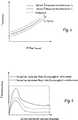
In diesem vierten Ausführungsbeispiel wird der Fall des Anlaufens des Motors eines Kompressors K betrachtet. Dabei wird der Motor bei t = 0 s eingeschaltet.4 zeigt entsprechend als durchgezogene Linien dargestellt die Verläufe für zwei verschiedene gemessene Ist-Motorstromwerte IIst ab dem Zeitpunkt des Einschaltens t = 0 s.In this fourth embodiment, the case of starting the engine of a compressor K is considered. The motor is switched on at t = 0 s. 4 shows correspondingly shown as solid lines the courses for two different measured actual motor current values IIs t = 0 s from the time of switching on.

Für den Motoranlauf ist in der Diagnoseeinheit30 ein entsprechender Verlauf eines Soll-Motorstromwerts ISoll hinterlegt, der in der4 gestrichelt dargestellt ist. Mit diesem zeitlichen Verlauf des Soll-Motorstromwerts ISoll wird der gemessene Ist-Motorstromwert IIst in der Diagnoseeinheit30 für jeden Messzeitpunkt verglichen und das Ergebnis bewertet. Ergibt sich aus diesem Vergleich, dass der gemessene Ist-Motorstromwert IIst den Soll-Motorstromwert ISoll des entsprechenden Zeitpunkts überschreitet, wird der Motor von der Stromzufuhr getrennt und eine Meldung ausgegeben. Die weiteren Möglichkeiten der Diagnoseeinheit40, mit einem Überschreiten des zulässigen Soll-Motorstromwerts ISoll umzugehen, entsprechen denen des ersten Ausführungsbeispiels.For the motor startup is in the diagnostic unit 30 a corresponding course of a desired motor current value Iset deposited in the 4 is shown in dashed lines. With this time profile of the desired motor current value ISoll , the measured actual motor current value IIst in thediagnostic unit 30 compared for each measurement time and the result is evaluated. If it results from this comparison that the measured actual motor current value Iactual exceeds the setpoint motor current value Isetpoint of the corresponding time point, the motor is disconnected from the power supply and a message is output. The other possibilities of thediagnostic unit 40 to deal with exceeding the allowable target motor current value ISoll correspond to those of the first embodiment.

In einem fünften Ausführungsbeispiel wird auf den Messwertaufnehmer zur Erfassung der Außenlufttemperatur T als Messwert MW4 verzichtet. Stattdessen wird die Außenlufttemperatur T über den Messwert MW2 als Temperatur TLamelle zwischen den Lamellen L des Verdampfers bzw. am Rohr des Verdampfers bestimmt. Dies ist sowohl für die Kompressionskältemaschine des ersten Ausführungsbeispiels als auch für die Brauchwasserwärmepumpe des dritten Ausführungsbeispiels möglich.In a fifth exemplary embodiment, the measured value recorder for detecting the outside air temperature T as the measured value MW4 is dispensed with. Instead, the outside air temperature T is determined via the measured value MW2 as the temperature Tlamella between the lamellae L of the evaporator or at the tube of the evaporator. This is possible both for the compression refrigerating machine of the first embodiment and for the service water heat pump of the third embodiment.

Für die Messung der Außenlufttemperatur T nach einer Bereitschaftsdauer, während der der Kompressor K längere Zeit ausgeschaltet war, kann direkt vor dem Einschalten des Kompressors K zunächst der Motor des Lüfters für z. B. eine Minute eingeschaltet werden. Hierdurch wird die Außenluft an den Lamellen L vorbeigeführt, so dass sich die Temperatur der Lamellen TLamelle nach einer gewissen Zeit, z. B. einer Minute, der Außenlufttemperatur T angleicht. Somit wird die Außenlufttemperatur T durch eine Messung der Temperatur TLamelle durch die Messeinheit10 erfasst und der Diagnoseeinheit30 zur Verfügung gestellt. Die Diagnoseeinheit30 kann dann mit diesem Messwert wie in den vorangegangenen Ausführungsbeispielen beschrieben verfahren.For the measurement of the outside air temperature T after a standby period during which the compressor K was switched off for a long time, the motor of the fan for z. B. be turned on for a minute. As a result, the outside air is guided past the fins L, so that the temperature of the fins Tlamella after a certain time, for. B. one minute, the outside air temperature T equalizes. Thus, the outside air temperature T is determined by measuring the temperature Tplate by the measuringunit 10 recorded and thediagnostic unit 30 made available. Thediagnostic unit 30 can then proceed with this measurement as described in the previous embodiments.

5 zeigt eine schematische Darstellung einer Messeinheit10 gemäß einem sechsten Ausführungsbeispiel, die zur Verwendung als Messeinheit10 in einem der vorherigen Ausführungsbeispiele geeignet ist. Die Messeinheit10 ist mit dem Motor100 eines Kompressors K und einem Lüfter110 verbunden. Die Messeinheit10 weist eine Messwertverarbeitungseinheit200 und eine Mikroprozessoreinheit600 auf. 5 shows a schematic representation of a measuringunit 10 according to a sixth embodiment, for use as a measuringunit 10 is suitable in one of the previous embodiments. The measuringunit 10 is with the engine 100 a compressor K and afan 110 connected. The measuringunit 10 has a measuredvalue processing unit 200 and amicroprocessor unit 600 on.

Die Messwertverarbeitungseinheit200 weist zwei Ringkernspulen400 auf, die jeweils auf einer Seite einer ersten Wicklung mit dem Motor100 des Kompressors K bzw. dem Lüfter110 verbunden sind und auf der anderen Seite der ersten Wicklung mit einem Nullleiter300. Die Ringkernspulen400 weisen jeweils eine zweite Wicklung auf, die auf der einen Seite mit Masse und auf der anderen Seite mit einem Messstellenumschalter500 verbunden sind. Dabei ist der Messstellenumschalter500 mit der Mikroprozessoreinheit600 verbunden und schaltet zwischen der zweiten Wicklung der Ringkernspule400, die mit dem Motor100 verbunden ist, und der Ringkernspule400, die mit dem Lüfter110 verbunden ist, um. Die Messwertverarbeitungseinheit200 weist ferner einen Tiefpassfilter700 auf, der mit beiden zweiten Wicklungen der Ringkernspulen400 verbunden ist.The measuredvalue processing unit 200 has twotoroidal coils 400 on, each on one side of a first winding with theengine 100 of the compressor K or thefan 110 are connected and on the other side of the first winding with a neutral 300 , Thetoroidal coils 400 each have a second winding on one side with ground and on the other side with ameasuring point switch 500 are connected. The measuring point switch is here 500 with themicroprocessor unit 600 connected and switches between the second winding of thetoroidal coil 400 that with theengine 100 is connected, and thetoroidal coil 400 that with thefan 110 is connected to. The measuredvalue processing unit 200 also has alow pass filter 700 on, with both second windings of thetoroidal coils 400 connected is.

Die Mikroprozessoreinheit600 weist einen Mikroprozessor und einen A/D-Wandler800 auf, der mit dem Tiefpassfilter700 der Messwertverarbeitungseinheit200 und dem Mikroprozessor verbunden ist.Themicroprocessor unit 600 has a microprocessor and an A /D converter 800 on that with the low-pass filter 700 the measuredvalue processing unit 200 and the microprocessor is connected.

Das Messprinzip der Messeinheit10 gemäß dem sechsten Ausführungsbeispiel ist als „Stromzange” bekannt und funktioniert nach dem Prinzip eines Stromtransformators. Der magnetische Fluss in den Ringkernspulen400 induziert einen elektrischen Strom, der ein tatsächliches Abbild des im Nullleiter300 der jeweiligen Ringkernspule400 fließenden Stromes ist. Die Ringkernspulen400 können gegenüber der Drahtzuleitung ein Wicklungsverhältnis von z. B. ca. 100 zu 1 aufweisen, um ein ausreichend stabiles Abbild des tatsächlich fließenden Stromes zu erzeugen.The measuring principle of the measuringunit 10 according to the sixth embodiment is known as "current clamp" and works on the principle of a current transformer. The magnetic flux in thetoroidal coils 400 induces an electric current that is an actual image of the neutral 300 the respectivetoroidal coil 400 flowing stream is. Thetoroidal coils 400 can with respect to the wire feed a winding ratio of z. B. about 100 to 1, in order to produce a sufficiently stable image of the actual flowing stream.

Die Umschaltung zwischen den beiden Ringkernspulen400 erfolgt durch den Messstellenumschalter500, der hierzu von dem Mikroprozessor der Mikroprozessoreinheit600 angesteuert wird. Das jeweils gemessene sinusförmige Stromsignal der Ringkernspule400 wird dem Tiefpassfilter700 zugeführt. Der Tiefpassfilter700 richtet das Stromsignal gleich und wandelt das gefilterte gemessene Stromsignal in ein linearisiertes Spannungssignal um. Außerdem wird mittels einer Zenerdiode (nicht dargestellt) eine Spannungsbegrenzung vorgenommen, die die Mikroprozessoreinheit600 vor zu hohen Spannungen am Eingang schützt. Das in dem A/D Wandler800 digitalisierte Signal wird dann in dem Mikroprozessor der Mikroprozessoreinheit600 weiterverarbeitet und über die Auswerteeinheit20 der Diagnoseeinheit30 zur Verfügung gestellt.Switching between the twotoroidal coils 400 is done by themeasuring point switch 500 for this purpose from the microprocessor of themicroprocessor unit 600 is controlled. The respectively measured sinusoidal current signal of thetoroidal coil 400 becomes the low-pass filter 700 fed. Thelow pass filter 700 rectifies the current signal and converts the filtered measured current signal into a linearized voltage signal. In addition, by means of a Zener diode (not shown) a voltage limit is made, which is themicroprocessor unit 600 protects against excessive voltages at the input. That in the A /D converter 800 digitized signal is then in the microprocessor of themicroprocessor unit 600 further processed and via theevaluation unit 20 thediagnostic unit 30 made available.

6 zeigt eine schematische Darstellung eines Tiefpassfilters700. 6 shows a schematic representation of a low-pass filter 700 ,

7 zeigt eine schematische Darstellung einer Messeinheit10 gemäß einem siebten Ausführungsbeispiel, die zur Verwendung als Messeinheit in einem der ersten bis fünften Ausführungsbeispiele geeignet ist. Bei dieser Messeinheit10 ist zusätzlich mindestens ein Relais105 mit Wechslerfunktion und eine Schmelzsicherung140 vorgesehen. Der Strom mindestens einer Komponente100,110 wird ausgehend vom Relaiskontakt115 entweder unter Umgehung der Schmelzsicherung140 über den Kontakt135 geführt oder beispielsweise im Störungsfall über den Kontakt125. Dadurch ergibt sich die Möglichkeit, im Störfall die Stromzufuhr dauerhaft zu unterbrechen. 7 shows a schematic representation of a measuringunit 10 according to a seventh embodiment, which is suitable for use as a measuring unit in one of the first to fifth embodiments. In this measuringunit 10 is additionally at least onerelay 105 with changer function and afuse 140 intended. The current of at least onecomponent 100 . 110 is starting from therelay contact 115 either bypassing thefuse 140 about thecontact 135 guided or, for example, in case of failure via thecontact 125 , This results in the possibility to permanently interrupt the power supply in case of failure.

8 zeigt eine schematische Darstellung einer Messeinheit10 gemäß einem achten Ausführungsbeispiel, die zur Verwendung als Messeinheit in einem der ersten bis fünften Ausführungsbeispiele geeignet ist. Die Messeinheit10 erkennt im Falle des Auftretens eines Fehlers eine Unterbrechung der Ringkernspule400 oder400a dadurch, dass der Summenstrom in der Mikroprozessoreinheit600 ausgewertet wird. Durch die Messeinheit10 gemäß des achten Ausführungsbeispiels der8 werden im Gegensatz zu den Messeinheiten10 der sechsten und siebten Ausführungsform der6 und7 in der Ringkernspule400a zunächst die Zuleitungen von beiden Motoren100 und110 geführt. Zusätzlich wird die Zuleitung eines Motors110 durch die Ringkernspule400 geführt. Aus dem gemessenen Summenstrom kann dann in der Mikroprozessoreinheit600 durch Subtraktion des Stromsignals aus der Ringkernspule400 von dem Stromsignal aus der Ringkernspule400a die Information des Stromverbrauchs des Motors100 ermittelt werden. Im Störungsfall wird bei dieser Zweitfehlerbetrachtung eine Unterbrechung einer von zwei Ringkernspulen400,400a erkannt. 8th shows a schematic representation of a measuringunit 10 according to an eighth embodiment, which is suitable for use as a measuring unit in any one of the first to fifth embodiments. The measuringunit 10 detects an interruption of the toroidal coil in the event of afault 400 or 400a in that the summation current in themicroprocessor unit 600 is evaluated. Through the measuringunit 10 according to the eighth embodiment of 8th be unlike themeasurement units 10 the sixth and seventh embodiment of the 6 and 7 in thetoroidal coil 400a First, the supply lines of bothengines 100 and 110 guided. In addition, the supply line of anengine 110 through thetoroidal coil 400 guided. From the measured total current can then in themicroprocessor unit 600 by subtracting the current signal from thetoroidal coil 400 from the current signal from thetoroidal coil 400a the information of power consumption of theengine 100 be determined. In the event of a fault, an interruption of one of two toroidal coils occurs in this second-fault consideration 400 . 400a recognized.

Der Gedanke der Erfindung ist es, eine Vorrichtung bestehend aus Messwertaufnahme und Auswerteeinheit vorzuschlagen, die in einer Messeinheit mittels einer Messung des aufgenommenen Motorstromistwertes die mögliche Überhitzung der Motorwicklung durch einen Vergleich mit werksseitig vorgegebenen Motorstromaufnahmesollwerten in der Auswerteeinheit auswertet. Das Ergebnis der Auswertung wird einer Diagnoseeinheit zugeführt. In der Diagnoseeinheit wird der Vergleich bewertet. Das Ergebnis der Bewertung wird einer Steuereinheit zugeführt, die den Motorbetrieb z. B. nach mehrmaliger Überschreitung eines werkseitigen Stromaufnahmesollwertes temporär oder bei Überschreitung eines Maximalwertes dauerhaft unterbricht, weil zum Beispiel eine Störung vorliegt. Die Diagnoseeinheit ist ebenfalls mit einer Anzeigeeinheit verbunden, die ein akustisches oder ein optisches Signal generiert und auf eine Störung hinweist. Auf der Anzeigeeinheit ist ein Resetschalter angeordnet mittels dem die Störung quittiert wird. Das Resetsignal wird in der Diagnoseeinheit bewertet. Das Ergebnis der Bewertung führt zu einer Wiederaufnahme des Motorbetriebes oder zu einer Sperrung, die auf der Anzeigeeinheit dargestellt wird.The idea of the invention is to propose a device consisting of measured value recording and evaluation unit, which evaluates the possible overheating of the motor winding in a measuring unit by means of a measurement of the recorded actual motor current value by comparison with factory-set motor current setpoint values in the evaluation unit. The result of the evaluation is fed to a diagnostic unit. The comparison is evaluated in the diagnostic unit. The result of the evaluation is supplied to a control unit, which controls the engine operation z. B. after repeated exceeding of a factory power consumption setpoint temporarily or permanently interrupted when exceeding a maximum value, for example because of a fault. The diagnostic unit is also connected to a display unit which generates an acoustic or an optical signal and indicates a fault. On the display unit, a reset switch is arranged by means of which the fault is acknowledged. The reset signal is evaluated in the diagnostic unit. The result of the evaluation leads to a resumption of the motor operation or to a blocking, which is displayed on the display unit.

Ein Vergleich der Motorstromaufnahme-Istwerte mit vorgegebenen Motorstromaufnahme-Sollwerten kann mittels einer Messung mindestens eines oder weiterer Parameter aus dem Kältekreis durchgeführt werden. Weiterhin führt eine Betrachtung der zeitlichen Entwicklung der Motorstromaufnahme während des Motorstartes in der Diagnoseeinheit zu der Aussage, ob der Rotor bei vollständigem Druckausgleich läuft oder bei unvollständigem Druckausgleich steht.A comparison of the motor current consumption actual values with predetermined motor current consumption setpoint values can be carried out by means of a measurement of at least one or further parameters from the refrigeration circuit. Furthermore, a consideration of the temporal evolution of the motor current consumption during the engine start in the diagnostic unit leads to the statement as to whether the rotor runs with complete pressure equalization or with incomplete pressure equalization.

Claims (12)

Translated fromGerman
Fluidverdichter (K), mit einem ersten Elektromotor (100), einer Vorrichtung (1) zur Überwachung des ersten Elektromotors (100), wobei die Vorrichtung (1) zur Überwachung des ersten Elektromotors (100) aufweist: eine Messeinheit (10) zum Messen eines Ist-Antriebsstroms (IIst) des ersten Elektromotors (100), eine Diagnoseeinheit (30) zum Vergleichen eines ersten gemessenen Ist-Antriebsstroms (IIst) mit einem ersten vorgegebenen Soll-Antriebsstroms (ISoll), und eine Steuerungseinheit (40) zum Ausschalten des ersten Elektromotors (100), wenn der erste gemessene Ist-Antriebsstrom (IIst) den ersten vorgegebenen Soll-Antriebsstrom (ISoll) überschreitet.Fluid compressor (K), with a first electric motor ( 100 ), a device ( 1 ) for monitoring the first electric motor ( 100 ), the device ( 1 ) for monitoring the first electric motor ( 100 ) comprises: a measuring unit ( 10 ) for measuring an actual drive current (Iactual ) of the first electric motor ( 100 ), a diagnostic unit ( 30 ) For comparing a first measured actual drive current (Iactual) with a first predetermined target driving current (ISoll), and a control unit ( 40 ) for switching off the first electric motor ( 100 ) when the first measured actual drive current (Iactual ) exceeds the first predetermined target drive current (Isetpoint ).Fluidverdichter (K)) nach Anspruch 1, wobei die Vorrichtung (1) zur Überwachung des ersten Elektromotors (100) ferner aufweist: einen Aktor (41) zum Trennen des ersten Elektromotors (100) von der Spannungsversorgung, und/oder eine Auswerteeinheit (20) zum Verarbeiten des gemessenen Ist-Antriebsstroms (IIst), und/oder eine Anzeigeeinheit (50) zum Anzeigen einer Meldung, und/oder einer Eingabeeinheit (51) zum Tätigen einer Eingabe.Fluid compressor (K)) according to claim 1, wherein the device ( 1 ) for monitoring the first electric motor ( 100 ) further comprises: an actuator ( 41 ) for disconnecting the first electric motor ( 100 ) from the power supply, and / or an evaluation unit ( 20 ) for processing the measured actual drive current (Iactual ), and / or a display unit ( 50 ) for displaying a message, and / or an input unit ( 51 ) to make an entry.Fluidverdichter (K) nach einem der vorherigen Ansprüche, wobei die Diagnoseeinheit (30) den ersten Elektromotor (100) über die Steuerungseinheit (40) erneut einschaltet, falls nach einer vorbestimmten Zeitdauer ein zweiter gemessener Ist-Antriebsstrom (IIst) den ersten vorgegebenen Soll-Antriebsstrom (ISoll) wieder unterschreitet oder bei erneutem Einschalten des ersten Elektromotors (100).Fluid compressor (K) according to one of the preceding claims, wherein the diagnostic unit ( 30 ) the first electric motor ( 100 ) via the control unit ( 40 ) again, if after a predetermined period of time a second measured actual drive current (Iactual ) falls below the first predetermined setpoint drive current (Isetpoint ) again or when the first electric motor is switched on again ( 100 ).Fluidverdichter (K) nach einem der vorherigen Ansprüche, wobei die Diagnoseeinheit (30) die Steuerungseinheit (40) zum dauerhaften Ausschalten des ersten Elektromotors (100) veranlasst, falls i die Anzahl der Vergleiche des gemessenen Ist-Antriebsstroms (IIst) mit dem ersten vorgegebenen Soll-Antriebsstrom (ISoll), die zu einem Ausschalten des ersten Elektromotors (100) geführt haben, innerhalb einer vorgegebenen Zeitdauer eine vorgegebene Anzahl überschreitet, und/oder ii ein gemessener Ist-Antriebsstrom (IIst) einen zweiten vorgegebenen Soll-Antriebsstrom (ISoll,max) überschreitet.Fluid compressor (K) according to one of the preceding claims, wherein the diagnostic unit ( 30 ) the control unit ( 40 ) for permanently switching off the first electric motor ( 100 ) causes, if i, the number of comparisons of the measured actual drive current (Iactual ) with the first predetermined setpoint Drive current (Isetpoint ), which is to switch off the first electric motor ( 100 ), within a predetermined period of time exceeds a predetermined number, and / or ii a measured actual drive current (Iactual ) exceeds a second predetermined desired drive current (Isetpoint, max ).Fluidverdichter (K) nach einem der vorherigen Ansprüche, wobei die Messeinheit (10) ferner eine erste Temperatur (TLamelle), eine zweite Temperatur (TWW) und eine dritte Temperatur (Tn) misst, die Diagnoseeinheit (30) eine Temperaturdifferenz (ΔT) zwischen der ersten Temperatur (TLamelle) und der zweiten Temperatur (TWW) bildet, und die Diagnoseeinheit (30) den gemessenen Ist-Antriebsstrom (IIst) mit dem ersten vorgegebenen Soll-Antriebsstrom (ISoll) unter Berücksichtigung der Temperaturdifferenz (ΔT) und der dritten Temperatur (Tn) vergleicht.Fluid compressor (K) according to one of the preceding claims, wherein the measuring unit ( 10 ) further measures a first temperature (Tlamella ), a second temperature (TWW ) and a third temperature (Tn ), the diagnostic unit ( 30 ) forms a temperature difference (ΔT) between the first temperature (Tplate ) and the second temperature (TWW ), and the diagnostic unit ( 30 ) compares the measured actual drive current (Iactual ) with the first predetermined desired drive current (Isetpoint ) taking into account the temperature difference (ΔT) and the third temperature (Tn ).Fluidverdichter (K) nach einem der Ansprüche 1 bis 4, wobei die Diagnoseeinheit (30) den gemessenen Ist-Antriebsstrom (IIst) mit einem zeitlichen Verlauf erster vorgegebener Soll-Antriebsstroms (ISoll) vergleicht.Fluid compressor (K) according to one of claims 1 to 4, wherein the diagnostic unit ( 30 ) compares the measured actual drive current (Iactual ) with a time course of the first predetermined desired drive current (Isetpoint ).Fluidverdichter (K) nach einem der vorherigen Ansprüche, wobei die Messeinheit (10) aufweist: eine erste Ringspule (400), die mit dem ersten Elektromotor (100) und einem ersten Kontakt eines Schalters (500) verbunden ist, eine zweite Ringspule (400), die mit einem zweiten Elektromotor (110) und einem zweiten Kontakt des Schalters (500) verbunden ist, und eine Mikroprozessoreinheit (600) zum Ansteuern des Schalters (500), um zwischen der ersten und zweiten Ringspule (400) umzuschalten, wobei die Mikroprozessoreinheit (600) der Messeinheit (10) entweder einen ersten gemessenen Ist-Antriebsstrom (IIst)des ersten Elektromotors (100) oder einen zweiten gemessenen Ist-Antriebsstrom (IIst) des zweiten Elektromotors (110) über die Auswerteeinheit (20) an die Diagnoseeinheit (30) übergibt.Fluid compressor (K) according to one of the preceding claims, wherein the measuring unit ( 10 ): a first annular coil ( 400 ) connected to the first electric motor ( 100 ) and a first contact of a switch ( 500 ), a second annular coil ( 400 ) connected to a second electric motor ( 110 ) and a second contact of the switch ( 500 ), and a microprocessor unit ( 600 ) for driving the switch ( 500 ) between the first and second toroidal coils ( 400 ), the microprocessor unit ( 600 ) of the measuring unit ( 10 ) either a first measured actual drive current (Iactual ) of the first electric motor ( 100 ) or a second measured actual drive current (Iactual ) of the second electric motor ( 110 ) via the evaluation unit ( 20 ) to the diagnostic unit ( 30 ) passes.Verfahren zur Überwachung eines Elektromotors (100) eines Fluidverdichters (K), mit den Schritten: Messen eines Ist-Antriebsstroms (IIst) eines Elektromotors (100), Vergleichen eines ersten gemessenen Ist-Antriebsstroms (IIst) mit einem ersten vorgegebenen Soll-Antriebsstrom (ISoll), und Ausschalten des Elektromotors (100) für den Fall des Vergleichens, dass der erste gemessene Ist-Antriebsstrom (IIst) den ersten vorgegebenen Soll-Antriebsstrom (ISoll) überschreitet.Method for monitoring an electric motor ( 100 ) of a fluid compressor (K), comprising the steps of: measuring an actual drive current (Iactual ) of an electric motor ( 100 ), Comparing a first measured actual drive current (Iactual ) with a first predetermined desired drive current (Isetpoint ), and switching off the electric motor ( 100 ) in the case of comparing that the first measured actual drive current (Iactual ) exceeds the first predetermined target drive current (Isetpoint ).Verfahren nach Anspruch 8, ferner mit den Schritten: Messen einer ersten Temperatur (TLamelle), einer zweiten Temperatur (TWW) und einer dritten Temperatur (Tn), Bilden einer Temperaturdifferenz (ΔT) zwischen der ersten Temperatur (TLamelle) und der zweiten Temperatur (TWW), und Vergleichen des gemessenen Ist-Antriebsstroms (IIst) mit dem ersten vorgegebenen Soll-Antriebsstrom (ISoll) unter Berücksichtigung der Temperaturdifferenz (ΔT) und der dritten Temperatur (Tn).The method of claim 8, further comprising the steps of: measuring a first temperature (Tlamella ), a second temperature (TWW ) and a third temperature (Tn ), forming a temperature difference (ΔT) between the first temperature (Tlamella ) and the second temperature (TWW ), and comparing the measured actual drive current (Iactual ) with the first predetermined target drive current (ISoll ) taking into account the temperature difference (.DELTA.T) and the third temperature (Tn ).Verfahren nach Anspruch 8 oder 9, ferner mit den Schritten: Einschalten eines Lüfters (110), Messen einer Temperatur (TLamelle) zwischen den Lamellen (L) eines Verdampfers einer Kältekompressionsmaschine oder Luft-Brauchwasserwärmepumpe als dritte Temperatur (Tn), und Einschalten eines Kompressors (K) der Kältekompressionsmaschine oder Luft-Brauchwasserwärmepumpe.The method of claim 8 or 9, further comprising the steps of: turning on a fan ( 110 ), Measuring a temperature (Tlamella ) between the fins (L) of an evaporator of a refrigeration compressor or air hot water heat pump as a third temperature (Tn ), and turning on a compressor (K) of the refrigeration compressor or air hot water heat pump.Vorrichtung (1) zur Überwachung eines Elektromotors (100) eines Fluidverdichters (K), mit: einer Messeinheit (10) zum Messen eines Wertes (IIst) des Antriebsstroms des Elektromotors (100), einer Diagnoseeinheit (30) zum Vergleichen eines ersten gemessenen Ist-Antriebsstroms (IIst) mit einem ersten vorgegebenen Soll-Antriebsstroms (ISoll), und einer Steuerungseinheit (40) zum Ausschalten des Elektromotors (100) auf Veranlassung der Diagnoseeinheit (30), wenn der erste gemessene Ist-Antriebsstrom (IIst) den ersten vorgegebenen Soll-Antriebsstrom (ISoll) überschreitet.Contraption ( 1 ) for monitoring an electric motor ( 100 ) of a fluid compressor (K), comprising: a measuring unit ( 10 ) for measuring a value (Iactual ) of the drive current of the electric motor ( 100 ), a diagnostic unit ( 30 ) for comparing a first measured actual drive current (Iactual ) with a first predetermined desired drive current (Isetpoint ), and a control unit ( 40 ) for switching off the electric motor ( 100 ) at the request of the diagnostic unit ( 30 ) when the first measured actual drive current (Iactual ) exceeds the first predetermined target drive current (Isetpoint ).Kompressionskältemaschine oder Wärmepumpe, mit einem Verflüssiger (E), einem Verdampfer (V), einem Drosselorgan (D1), und einem Fluidverdichter (K), wobei der Fluidverdichter (K) aufweist: einen ersten Elektromotor (100), und einer Vorrichtung (1) zur Überwachung des ersten Elektromotors (100) nach Anspruch 11.A compression refrigerating machine or heat pump, comprising a condenser (E), an evaporator (V), a throttle body (D1), and a fluid compressor (K), the fluid compressor (K) comprising: a first electric motor ( 100 ), and a device ( 1 ) for monitoring the first electric motor ( 100 ) according to claim 11.
DE2011100134372011-03-092011-03-09Fluid compressor for heat pump, has control unit that is provided to turn off electric motor, when actual drive current of motor exceeds predetermined desired drive currentCeasedDE102011013437A1 (en)

Priority Applications (1)

Application NumberPriority DateFiling DateTitle
DE201110013437DE102011013437A1 (en)2011-03-092011-03-09Fluid compressor for heat pump, has control unit that is provided to turn off electric motor, when actual drive current of motor exceeds predetermined desired drive current

Applications Claiming Priority (1)

Application NumberPriority DateFiling DateTitle
DE201110013437DE102011013437A1 (en)2011-03-092011-03-09Fluid compressor for heat pump, has control unit that is provided to turn off electric motor, when actual drive current of motor exceeds predetermined desired drive current

Publications (1)

Publication NumberPublication Date
DE102011013437A1true DE102011013437A1 (en)2012-09-13

Family

ID=46705378

Family Applications (1)

Application NumberTitlePriority DateFiling Date
DE201110013437CeasedDE102011013437A1 (en)2011-03-092011-03-09Fluid compressor for heat pump, has control unit that is provided to turn off electric motor, when actual drive current of motor exceeds predetermined desired drive current

Country Status (1)

CountryLink
DE (1)DE102011013437A1 (en)

Cited By (2)

* Cited by examiner, † Cited by third party
Publication numberPriority datePublication dateAssigneeTitle
DE102013021347A1 (en)*2013-12-142015-06-18Festo Ag & Co. Kg monitoring device
GB2611362A (en)*2021-10-042023-04-05Aspen Pumps LtdCondensate pump assembly & control methods

Cited By (2)

* Cited by examiner, † Cited by third party
Publication numberPriority datePublication dateAssigneeTitle
DE102013021347A1 (en)*2013-12-142015-06-18Festo Ag & Co. Kg monitoring device
GB2611362A (en)*2021-10-042023-04-05Aspen Pumps LtdCondensate pump assembly & control methods

Similar Documents

PublicationPublication DateTitle
DE69731576T2 (en) Defrost control method for air conditioning
DE3517222C2 (en)
DE3713869C2 (en)
EP1960850B1 (en)Control method for cooling an industrial plant
DE2126560A1 (en) PROTECTIVE CIRCUIT
DE2647092A1 (en) PROTECTION SYSTEM FOR AN ELECTRIC MOTOR
DE3517217A1 (en) OPERATING METHOD AND CONTROL ARRANGEMENT FOR A REFRIGERATION SYSTEM
DE3422110A1 (en) CONTROL CIRCUIT FOR AN AIR CONDITIONING
CN105092220A (en)Fault detection method and device for supercooling valve in supercooling device
DE3940523A1 (en) LEAK MONITOR FOR COOLING UNITS
DE102007001452A1 (en)Refrigerant e.g. carbon dioxide, under-filling determination method for air conditioning system of vehicle, involves determining difference of values based on identification of filling level, and determining measure for change of difference
DE102011013437A1 (en)Fluid compressor for heat pump, has control unit that is provided to turn off electric motor, when actual drive current of motor exceeds predetermined desired drive current
EP3037741A1 (en)Method for avoiding dry fire in electric continuous-flow heaters
EP1479984A1 (en)Method and apparatus for preventive failure detection by electronic controlled device
DE102005052042B4 (en) Method and system for controlling a compressor
EP4227612A1 (en)Method for testing a safety high-pressure switch
EP0352217B1 (en)Process for controlling and supervising a fuel-heated apparatus with the use of at least one microcomputer system, and apparatus to carry out this process
DE102009012942A1 (en)Compressor e.g. ventilator, has electric motor arranged in crankcase, and control device for releasing control measures depending on comparison of measured values with stored limit values
EP1994620B1 (en)Protective device and method for monitoring the appliance temperature of an appliance
DE10114823A1 (en) Method and device for monitoring burners
DE102012108983B4 (en) Method for controlling a compressor of a refrigeration system and a refrigeration system
WO2009056336A2 (en)Method and device for securing refrigeration compressors
DE102004055850A1 (en)Operating method for a water heater uses heating units connected to a power network by electronic switches likes triacs with their gate electrodes triggered by a control device as required
DE10206245A1 (en)To dry a gas it is cooled at a heat exchanger, where a coolant circuit has a compressor operated by a controlled electromotor with reduced energy consumption
DE4408798B4 (en) Control system of a device for cooling an internal combustion engine

Legal Events

DateCodeTitleDescription
R012Request for examination validly filed
R016Response to examination communication
R002Refusal decision in examination/registration proceedings
R003Refusal decision now final

[8]ページ先頭

©2009-2025 Movatter.jp