DE102011011244A1 - Medical instrument - Google Patents
Medical instrumentDownload PDFInfo
- Publication number
- DE102011011244A1 DE102011011244A1DE102011011244ADE102011011244ADE102011011244A1DE 102011011244 A1DE102011011244 A1DE 102011011244A1DE 102011011244 ADE102011011244 ADE 102011011244ADE 102011011244 ADE102011011244 ADE 102011011244ADE 102011011244 A1DE102011011244 A1DE 102011011244A1
- Authority
- DE
- Germany
- Prior art keywords
- shaft
- medical instrument
- handle
- drive
- longitudinal axis
- Prior art date
- Legal status (The legal status is an assumption and is not a legal conclusion. Google has not performed a legal analysis and makes no representation as to the accuracy of the status listed.)
- Withdrawn
Links
- 210000001331noseAnatomy0.000claimsdescription3
- BUHVIAUBTBOHAG-FOYDDCNASA-N(2r,3r,4s,5r)-2-[6-[[2-(3,5-dimethoxyphenyl)-2-(2-methylphenyl)ethyl]amino]purin-9-yl]-5-(hydroxymethyl)oxolane-3,4-diolChemical compoundCOC1=CC(OC)=CC(C(CNC=2C=3N=CN(C=3N=CN=2)[C@H]2[C@@H]([C@H](O)[C@@H](CO)O2)O)C=2C(=CC=CC=2)C)=C1BUHVIAUBTBOHAG-FOYDDCNASA-N0.000description1
- 238000010276constructionMethods0.000description1
- 238000006073displacement reactionMethods0.000description1
- 210000003813thumbAnatomy0.000description1
- 230000007704transitionEffects0.000description1
Images


Classifications
- A—HUMAN NECESSITIES
- A61—MEDICAL OR VETERINARY SCIENCE; HYGIENE
- A61B—DIAGNOSIS; SURGERY; IDENTIFICATION
- A61B17/00—Surgical instruments, devices or methods
- A61B17/28—Surgical forceps
- A61B17/29—Forceps for use in minimally invasive surgery
- A—HUMAN NECESSITIES
- A61—MEDICAL OR VETERINARY SCIENCE; HYGIENE
- A61B—DIAGNOSIS; SURGERY; IDENTIFICATION
- A61B17/00—Surgical instruments, devices or methods
- A61B17/28—Surgical forceps
- A61B17/29—Forceps for use in minimally invasive surgery
- A61B2017/2901—Details of shaft
- A61B2017/2904—Details of shaft curved, but rigid
- A—HUMAN NECESSITIES
- A61—MEDICAL OR VETERINARY SCIENCE; HYGIENE
- A61B—DIAGNOSIS; SURGERY; IDENTIFICATION
- A61B17/00—Surgical instruments, devices or methods
- A61B17/28—Surgical forceps
- A61B17/29—Forceps for use in minimally invasive surgery
- A61B2017/2926—Details of heads or jaws
- A61B2017/2927—Details of heads or jaws the angular position of the head being adjustable with respect to the shaft
- A61B2017/2929—Details of heads or jaws the angular position of the head being adjustable with respect to the shaft with a head rotatable about the longitudinal axis of the shaft
Landscapes
- Health & Medical Sciences (AREA)
- Surgery (AREA)
- Life Sciences & Earth Sciences (AREA)
- Biomedical Technology (AREA)
- Nuclear Medicine, Radiotherapy & Molecular Imaging (AREA)
- Engineering & Computer Science (AREA)
- Ophthalmology & Optometry (AREA)
- Heart & Thoracic Surgery (AREA)
- Medical Informatics (AREA)
- Molecular Biology (AREA)
- Animal Behavior & Ethology (AREA)
- General Health & Medical Sciences (AREA)
- Public Health (AREA)
- Veterinary Medicine (AREA)
- Surgical Instruments (AREA)
Abstract
Translated fromGermanDescription
Translated fromGermanDie Erfindung betrifft ein medizinisches Instrument mit einem hohlen Schaft und einer am proximalen Ende des Schaftes angeordneten Handhabe, wobei der Schaft über Antrieb um seine Längsachse verdrehbar ist.The invention relates to a medical instrument having a hollow shaft and a handle arranged at the proximal end of the shaft, wherein the shaft is rotatable about its longitudinal axis via drive.
Bei medizinischen Instrumenten mit einem gebogenen Schaft ist es vorteilhaft, dass der Schaft über einen Antrieb um die Längsachse des Schaftes verdrehbar ist, um ohne Verdrehung der Haltehand eine stets optimale Ausrichtung des medizinischen Instruments zum Operationsgebiet zu gewährleisten.In medical instruments with a curved shaft, it is advantageous that the shaft is rotatable about a drive about the longitudinal axis of the shaft in order to ensure an always optimal alignment of the medical instrument to the operating area without rotation of the holding hand.
Ein gattungsgemäßes medizinisches Instrument ist beispielsweise aus der
Davon ausgehend liegt der Erfindung die Aufgabe zugrunde, ein medizinisches Instrument der eingangs genannten Art zu schaffen, dessen Antrieb eine einfache und sichere Handhabung der Schaftverdrehung ermöglicht.Based on this, the present invention seeks to provide a medical instrument of the type mentioned, the drive allows easy and safe handling of the shaft rotation.
Die Lösung dieser Aufgabenstellung ist erfindungsgemäß dadurch gekennzeichnet, dass der Antrieb als sowohl um die Längsachse des Schaftes verdrehbares als auch in Längsrichtung des Schaftes verlagerbares Stellrad ausgebildet ist.The solution to this problem is inventively characterized in that the drive is designed as both about the longitudinal axis of the shaft rotatable and displaceable in the longitudinal direction of the shaft thumbwheel.
Durch die erfindungsgemäße Ausgestaltung des Antriebs als sowohl verdrehbares als auch axial verschiebbares Stellrad ist es erstmalig möglich, eine zuverlässige Arretierung des Stellrads in der jeweiligen Verdrehstellung des Schaftes zu gewährleisten, da das ausschließlich in der axial verschobenen Position verdrehbare Stellrad zwischen einer die Verdrehung des Schaftes um die Längsachse des Schaftes freigebenden Stellung und einer den Schaft arretierenden Stellung in Längsrichtung des Schaftes verlagerbar ist.Due to the inventive design of the drive as both rotatable and axially displaceable thumb wheel, it is possible for the first time to ensure a reliable locking of the thumbwheel in the respective rotational position of the shaft, since the rotatable exclusively in the axially displaced position wheel between a rotation of the shaft to the longitudinal axis of the shaft releasing position and a shaft locking position in the longitudinal direction of the shaft is displaced.
Mit einer ersten Ausführungsform der Erfindung wird vorgeschlagen, dass der Antrieb im Bereich des distalen Endes der Handhabe angeordnet ist.With a first embodiment of the invention, it is proposed that the drive is arranged in the region of the distal end of the handle.
Gemäß einer alternativen zweiten erfindungsgemäßen Ausführungsform wird vorgeschlagen, dass der Antrieb im Bereich des proximalen Endes des Schaftes angeordnet ist. In beiden Fällen ist es erforderlich, dass der Antrieb, beispielsweise durch eine kraftschlüssige oder formschlüssige Verbindung, so mit dem Schaft zusammenwirkt, dass durch das Betätigen des Antriebs, beispielsweise das Verdrehen des Stellrads, der Schaft um seine Längsachse verdreht werden kann.According to an alternative second embodiment of the invention it is proposed that the drive is arranged in the region of the proximal end of the shaft. In both cases, it is necessary that the drive, for example, by a non-positive or positive connection, so cooperates with the shaft that can be rotated about its longitudinal axis by operating the drive, for example, the rotation of the thumbwheel, the shaft.
Gemäß einer praktischen Ausführungsform der Erfindung wird vorgeschlagen, dass das Stellrad gegen die Kraft mindestens eines Federelements in Längsrichtung des Schaftes verlagerbar ist, um eine zusätzliche Sicherheit gegen ein versehentliches Verdrehen des Stellrads und somit auch des Schaftes zu schaffen. Vorzugsweise ist das Stellrad über das mindestens eine Federelement in Richtung auf die den Schaft arretierende Stellung vorgespannt, so dass das Stellrad automatisch in die arretierende Stellung zurückkehrt, wenn keine Kraft in axialer Richtung mehr auf das Stellrad ausgeübt wird.According to a practical embodiment of the invention it is proposed that the setting wheel against the force of at least one spring element in the longitudinal direction of the shaft is displaceable in order to provide additional security against accidental rotation of the setting wheel and thus also the shaft. Preferably, the thumbwheel is biased over the at least one spring element in the direction of the shaft locking position, so that the thumbwheel automatically returns to the locking position when no force is exerted in the axial direction more on the thumbwheel.
Das Arretieren des Stellrads in der jeweiligen Verdrehposition des Schaftes erfolgt erfindungsgemäß über am Stellrad und an der Handhabe ausgebildete, miteinander korrespondierende Rastelemente, über die der Schaft in vorgegebenen Raststufen um die Längsachse des Schaftes verdrehbar an der Handhabe festlegbar ist.The locking of the thumbwheel in the respective rotational position of the shaft is carried out according to the invention formed on the thumbwheel and the handle, mutually corresponding locking elements over which the shaft in predetermined latching steps about the longitudinal axis of the shaft is rotatably secured to the handle.
Mit einer bevorzugten Ausführungsform der Erfindung wird vorgeschlagen, dass die Rastelemente koaxial um die Längsachse des Schaftes angeordnet sind, wobei die Rastelemente vorzugsweise als am Stellrad angeordnete Raststifte oder Rastnasen und an der Handhabe ausgebildete Rastnuten ausgebildet sind.With a preferred embodiment of the invention, it is proposed that the latching elements are arranged coaxially about the longitudinal axis of the shaft, wherein the latching elements are preferably formed as arranged on the adjusting knob locking pins or latching noses and formed on the handle locking grooves.
Die Rastnuten sind gemäß einer praktischen Ausgestaltungsform der Erfindung in einer am distalen Ende der Handhabe angeordneten Rastscheibe ausgebildet.The locking grooves are formed according to a practical embodiment of the invention in a arranged at the distal end of the handle latching disc.
Schließlich wird mit der Erfindung vorgeschlagen, dass der Schaft zumindest abschnittweise gegenüber der Längsachse des Schaftes abgewinkelt ausgebildet ist.Finally, it is proposed with the invention that the shaft is at least partially angled with respect to the longitudinal axis of the shaft.
Zur Anordnung des für die Verdrehung des Schaftes benötigten Antriebs bieten sich erfindungsgemäß zwei Ausführungsformen an, nämlich die Anordnung des Antriebs im Bereich des distalen Endes der Handhabe oder alternativ die Anordnung des Antriebs im Bereich des proximalen Endes des Schaftes.For the arrangement of the drive required for the rotation of the shaft, two embodiments are provided according to the invention, namely the arrangement of the drive in the region of the distal end of the handle or alternatively the arrangement of the drive in the region of the proximal end of the shaft.
Weitere Merkmale und Vorteile der Erfindung ergeben sich anhand der zugehörigen Zeichnungen, in denen zwei Ausführungsbeispiele eines erfindungsgemäßen medizinischen Instruments nur beispielhaft dargestellt sind, ohne die Erfindung auf diese Ausführungsbeispiele zu beschränken. In den Zeichnungen zeigt:Further features and advantages of the invention will become apparent from the accompanying drawings in which two embodiments of a medical instrument according to the invention only are shown by way of example, without limiting the invention to these embodiments. In the drawings shows:
Das in Abbildung
Um ohne ein Verdrehen der Haltehand eine stets optimale Ausrichtung des gebogenen Schaftes
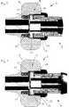
Bei der dargestellten Ausführungsform ist der Antrieb
Der Aufbau des Antriebs
Der Antrieb
Nur in der in axialer Richtung des Schaftes
Das Arretieren des Schaftes
Bei der in
Die Rastnuten
Die Abbildungen
Alternativ zu den dargestellten Ausführungsformen ist es selbstverständlich auch möglich, die Anordnung der Rastelemente
Um eine zusätzliche Sicherheit gegen ein versehentliches Verdrehen des Stellrads
Die Handhabung des zuvor insbesondere anhand der Abbildungen
Um den Schaft
Sobald der Bediener keinen Druck in axialer Richtung mehr auf das Stellrad
Alternativ zur der dargestellten und zuvor beschriebenen Ausgestaltungsform ist es selbstverständlich auch möglich, die Axialverlagerung des Stellrads
Ein wie zuvor beschrieben ausgebildetes medizinisches Instrument
BezugszeichenlisteLIST OF REFERENCE NUMBERS
- 11
- medizinisches Instrumentmedical instrument
- 22
- Schaftshaft
- 33
- Griffteilhandle part
- 44
- Griffteilhandle part
- 55
- Handhabehandle
- 66
- Längsachselongitudinal axis
- 77
- Antriebdrive
- 88th
- Stellradthumbwheel
- 99
- Rastelementlocking element
- 1010
- RaststiftPlunger
- 1111
- Rastnutlocking groove
- 1212
- DurchgangsbohrungThrough Hole
- 1313
- Rastscheibelocking disc
- 1414
- Rastnaselocking lug
- 1515
- Federelementspring element
ZITATE ENTHALTEN IN DER BESCHREIBUNG QUOTES INCLUDE IN THE DESCRIPTION
Diese Liste der vom Anmelder aufgeführten Dokumente wurde automatisiert erzeugt und ist ausschließlich zur besseren Information des Lesers aufgenommen. Die Liste ist nicht Bestandteil der deutschen Patent- bzw. Gebrauchsmusteranmeldung. Das DPMA übernimmt keinerlei Haftung für etwaige Fehler oder Auslassungen.This list of the documents listed by the applicant has been generated automatically and is included solely for the better information of the reader. The list is not part of the German patent or utility model application. The DPMA assumes no liability for any errors or omissions.
Zitierte PatentliteraturCited patent literature
- DE 3711377 C2[0003]DE 3711377 C2[0003]
Claims (11)
Translated fromGermanPriority Applications (3)
| Application Number | Priority Date | Filing Date | Title |
|---|---|---|---|
| DE102011011244ADE102011011244A1 (en) | 2011-02-15 | 2011-02-15 | Medical instrument |
| EP12000834AEP2489315A1 (en) | 2011-02-15 | 2012-02-09 | Medical instrument |
| US13/397,432US20120209255A1 (en) | 2011-02-15 | 2012-02-15 | Medical instrument |
Applications Claiming Priority (1)
| Application Number | Priority Date | Filing Date | Title |
|---|---|---|---|
| DE102011011244ADE102011011244A1 (en) | 2011-02-15 | 2011-02-15 | Medical instrument |
Publications (1)
| Publication Number | Publication Date |
|---|---|
| DE102011011244A1true DE102011011244A1 (en) | 2012-08-16 |
Family
ID=45654918
Family Applications (1)
| Application Number | Title | Priority Date | Filing Date |
|---|---|---|---|
| DE102011011244AWithdrawnDE102011011244A1 (en) | 2011-02-15 | 2011-02-15 | Medical instrument |
Country Status (3)
| Country | Link |
|---|---|
| US (1) | US20120209255A1 (en) |
| EP (1) | EP2489315A1 (en) |
| DE (1) | DE102011011244A1 (en) |
Families Citing this family (7)
| Publication number | Priority date | Publication date | Assignee | Title |
|---|---|---|---|---|
| DE102013100759A1 (en) | 2013-01-25 | 2014-07-31 | Karl Storz Gmbh & Co. Kg | Medical instrument |
| USD757935S1 (en)* | 2014-02-06 | 2016-05-31 | Karl Storz Endoscopy-America, Inc. | Rotation wheel extension |
| EP3164086B1 (en)* | 2014-07-01 | 2020-04-08 | Boston Scientific Scimed, Inc. | Overlapped braid termination |
| USD762454S1 (en)* | 2014-07-11 | 2016-08-02 | Karl Storz Gmbh & Co. Kg | Rotation wheel extension |
| CN113648029B (en)* | 2016-03-24 | 2025-03-14 | 史赛克欧洲控股I有限责任公司 | Surgical instrument having a cutting assembly with a grip |
| USD832436S1 (en)* | 2017-02-16 | 2018-10-30 | Ergosurg Gmbh | Electromagnetic localizer |
| DE102022119980A1 (en)* | 2022-08-09 | 2024-02-15 | Aesculap Ag | Medical motor handpiece with locking and/or stop unit |
Citations (4)
| Publication number | Priority date | Publication date | Assignee | Title |
|---|---|---|---|---|
| DE1929619U (en)* | 1965-09-01 | 1965-12-23 | Karl Storz | DEVICE FOR THE AXIAL MOVEMENT OF A GRIPPING OR CUTTING INSTRUMENT ARRANGED AT THE DISTAL END OF AN ENDOSCOPE. |
| DE3711377C2 (en) | 1986-04-14 | 1997-02-13 | I Melbourne Greenberg | Surgical instrument |
| US5609601A (en)* | 1994-09-23 | 1997-03-11 | United States Surgical Corporation | Endoscopic surgical apparatus with rotation lock |
| DE10214810A1 (en)* | 2002-04-04 | 2003-08-21 | Wolf Gmbh Richard | Forceps in form o f shaft has proximal end as rotary wheel, housing, operating bar, and engaging cogs |
Family Cites Families (5)
| Publication number | Priority date | Publication date | Assignee | Title |
|---|---|---|---|---|
| US4440170A (en)* | 1979-03-06 | 1984-04-03 | Ethicon, Inc. | Surgical clip applying instrument |
| US5352235A (en)* | 1992-03-16 | 1994-10-04 | Tibor Koros | Laparoscopic grasper and cutter |
| US5833692A (en)* | 1993-01-29 | 1998-11-10 | Smith & Nephew, Inc. | Surgical instrument |
| DE59900101D1 (en)* | 1999-04-29 | 2001-06-28 | Storz Karl Gmbh & Co Kg | Medical instrument for tissue preparation |
| US7950560B2 (en)* | 2007-04-13 | 2011-05-31 | Tyco Healthcare Group Lp | Powered surgical instrument |
- 2011
- 2011-02-15DEDE102011011244Apatent/DE102011011244A1/ennot_activeWithdrawn
- 2012
- 2012-02-09EPEP12000834Apatent/EP2489315A1/ennot_activeWithdrawn
- 2012-02-15USUS13/397,432patent/US20120209255A1/ennot_activeAbandoned
Patent Citations (4)
| Publication number | Priority date | Publication date | Assignee | Title |
|---|---|---|---|---|
| DE1929619U (en)* | 1965-09-01 | 1965-12-23 | Karl Storz | DEVICE FOR THE AXIAL MOVEMENT OF A GRIPPING OR CUTTING INSTRUMENT ARRANGED AT THE DISTAL END OF AN ENDOSCOPE. |
| DE3711377C2 (en) | 1986-04-14 | 1997-02-13 | I Melbourne Greenberg | Surgical instrument |
| US5609601A (en)* | 1994-09-23 | 1997-03-11 | United States Surgical Corporation | Endoscopic surgical apparatus with rotation lock |
| DE10214810A1 (en)* | 2002-04-04 | 2003-08-21 | Wolf Gmbh Richard | Forceps in form o f shaft has proximal end as rotary wheel, housing, operating bar, and engaging cogs |
Also Published As
| Publication number | Publication date |
|---|---|
| US20120209255A1 (en) | 2012-08-16 |
| EP2489315A1 (en) | 2012-08-22 |
Similar Documents
| Publication | Publication Date | Title |
|---|---|---|
| EP2220991B1 (en) | Instrument with self-releasing adjustment wheel | |
| DE102011011244A1 (en) | Medical instrument | |
| DE202017101615U1 (en) | torque wrench | |
| DE102009053966A1 (en) | Arrangement and method for connecting an accessory to an operating table | |
| DE10141234A1 (en) | System with a surgical needle and a handle | |
| EP3380026A1 (en) | Handling instrument for a bone screw | |
| DE102015110415A1 (en) | Surgery handle with internal and spring-biased anti-rotation unit | |
| DE19514098A1 (en) | Coupling for tubular shaft instruments | |
| EP1289434A1 (en) | Medical instrument | |
| WO2013064487A1 (en) | Handle for a medical instrument | |
| DE102013103544A1 (en) | Clamping device for releasably securing a device housing to a mounting rail | |
| DE102006047674A1 (en) | Screwdriver for handling a screw in the human or animal body | |
| DE10060769C2 (en) | Medical instrument | |
| DE4425705C2 (en) | Endoscopic instrument | |
| DE1791013C2 (en) | Coupling for connecting a dental handpiece or angle piece to an electric drive motor designed as a miniature motor | |
| DE202016002850U1 (en) | Surgical hand instrument | |
| DE102010013916A1 (en) | Medical instrument | |
| DE102021208391A1 (en) | medical instrument | |
| DE102010015997A1 (en) | hinge | |
| DE202007015878U1 (en) | Surgical instrument set | |
| DE202007000427U1 (en) | Surgical handle and surgical instrument | |
| DE202013008111U1 (en) | Twist / Trilock carabiner | |
| DE102011083331A1 (en) | gripping instrument | |
| DE369752C (en) | Lock with rack bolt | |
| EP2759270A1 (en) | Medical instrument |
Legal Events
| Date | Code | Title | Description |
|---|---|---|---|
| R163 | Identified publications notified | ||
| R119 | Application deemed withdrawn, or ip right lapsed, due to non-payment of renewal fee | ||
| R119 | Application deemed withdrawn, or ip right lapsed, due to non-payment of renewal fee | Effective date:20140902 |