DE102011007914A1 - Data communication interface for an agricultural utility vehicle - Google Patents
Data communication interface for an agricultural utility vehicleDownload PDFInfo
- Publication number
- DE102011007914A1 DE102011007914A1DE102011007914ADE102011007914ADE102011007914A1DE 102011007914 A1DE102011007914 A1DE 102011007914A1DE 102011007914 ADE102011007914 ADE 102011007914ADE 102011007914 ADE102011007914 ADE 102011007914ADE 102011007914 A1DE102011007914 A1DE 102011007914A1
- Authority
- DE
- Germany
- Prior art keywords
- data communication
- communication network
- data
- interface
- network
- Prior art date
- Legal status (The legal status is an assumption and is not a legal conclusion. Google has not performed a legal analysis and makes no representation as to the accuracy of the status listed.)
- Withdrawn
Links
Images


Classifications
- G—PHYSICS
- G06—COMPUTING OR CALCULATING; COUNTING
- G06F—ELECTRIC DIGITAL DATA PROCESSING
- G06F13/00—Interconnection of, or transfer of information or other signals between, memories, input/output devices or central processing units
- G06F13/38—Information transfer, e.g. on bus
- G06F13/40—Bus structure
- G06F13/4063—Device-to-bus coupling
- G06F13/4068—Electrical coupling
- A—HUMAN NECESSITIES
- A01—AGRICULTURE; FORESTRY; ANIMAL HUSBANDRY; HUNTING; TRAPPING; FISHING
- A01B—SOIL WORKING IN AGRICULTURE OR FORESTRY; PARTS, DETAILS, OR ACCESSORIES OF AGRICULTURAL MACHINES OR IMPLEMENTS, IN GENERAL
- A01B59/00—Devices specially adapted for connection between animals or tractors and agricultural machines or implements
- A—HUMAN NECESSITIES
- A01—AGRICULTURE; FORESTRY; ANIMAL HUSBANDRY; HUNTING; TRAPPING; FISHING
- A01B—SOIL WORKING IN AGRICULTURE OR FORESTRY; PARTS, DETAILS, OR ACCESSORIES OF AGRICULTURAL MACHINES OR IMPLEMENTS, IN GENERAL
- A01B79/00—Methods for working soil
- A01B79/005—Precision agriculture
- G—PHYSICS
- G06—COMPUTING OR CALCULATING; COUNTING
- G06F—ELECTRIC DIGITAL DATA PROCESSING
- G06F13/00—Interconnection of, or transfer of information or other signals between, memories, input/output devices or central processing units
- G06F13/38—Information transfer, e.g. on bus
- G06F13/382—Information transfer, e.g. on bus using universal interface adapter
- G06F13/385—Information transfer, e.g. on bus using universal interface adapter for adaptation of a particular data processing system to different peripheral devices
- G—PHYSICS
- G06—COMPUTING OR CALCULATING; COUNTING
- G06F—ELECTRIC DIGITAL DATA PROCESSING
- G06F13/00—Interconnection of, or transfer of information or other signals between, memories, input/output devices or central processing units
- G06F13/38—Information transfer, e.g. on bus
- G06F13/40—Bus structure
- G06F13/4004—Coupling between buses
- G06F13/4022—Coupling between buses using switching circuits, e.g. switching matrix, connection or expansion network
- H—ELECTRICITY
- H04—ELECTRIC COMMUNICATION TECHNIQUE
- H04L—TRANSMISSION OF DIGITAL INFORMATION, e.g. TELEGRAPHIC COMMUNICATION
- H04L67/00—Network arrangements or protocols for supporting network services or applications
- H04L67/01—Protocols
- H04L67/12—Protocols specially adapted for proprietary or special-purpose networking environments, e.g. medical networks, sensor networks, networks in vehicles or remote metering networks
- H—ELECTRICITY
- H04—ELECTRIC COMMUNICATION TECHNIQUE
- H04L—TRANSMISSION OF DIGITAL INFORMATION, e.g. TELEGRAPHIC COMMUNICATION
- H04L12/00—Data switching networks
- H04L12/28—Data switching networks characterised by path configuration, e.g. LAN [Local Area Networks] or WAN [Wide Area Networks]
- H04L12/40—Bus networks
- H04L2012/40208—Bus networks characterized by the use of a particular bus standard
- H04L2012/40215—Controller Area Network CAN
- H—ELECTRICITY
- H04—ELECTRIC COMMUNICATION TECHNIQUE
- H04L—TRANSMISSION OF DIGITAL INFORMATION, e.g. TELEGRAPHIC COMMUNICATION
- H04L12/00—Data switching networks
- H04L12/28—Data switching networks characterised by path configuration, e.g. LAN [Local Area Networks] or WAN [Wide Area Networks]
- H04L12/40—Bus networks
- H04L2012/40267—Bus for use in transportation systems
- H04L2012/40273—Bus for use in transportation systems the transportation system being a vehicle
Landscapes
- Engineering & Computer Science (AREA)
- Theoretical Computer Science (AREA)
- General Engineering & Computer Science (AREA)
- Life Sciences & Earth Sciences (AREA)
- Physics & Mathematics (AREA)
- General Physics & Mathematics (AREA)
- Computer Hardware Design (AREA)
- Environmental Sciences (AREA)
- Mechanical Engineering (AREA)
- Soil Sciences (AREA)
- General Health & Medical Sciences (AREA)
- Mathematical Physics (AREA)
- Health & Medical Sciences (AREA)
- Computing Systems (AREA)
- Zoology (AREA)
- Medical Informatics (AREA)
- Computer Networks & Wireless Communication (AREA)
- Signal Processing (AREA)
- Dc Digital Transmission (AREA)
- Small-Scale Networks (AREA)
- Agricultural Machines (AREA)
Abstract
Translated fromGermanDescription
Translated fromGermanDie Erfindung betrifft eine Datenkommunikationsschnittstelle für ein landwirtschaftliches Nutzfahrzeug, insbesondere einen landwirtschaftlichen Traktor.The invention relates to a data communication interface for an agricultural utility vehicle, in particular an agricultural tractor.
Moderne landwirtschaftliche Nutzfahrzeuge weisen in aller Regel ein fahrzeuginternes Datenkommunikationsnetzwerk zur Vernetzung diverser Steuergeräte auf. Hierbei ist im Falle landwirtschaftlicher Traktoren eine zunehmende Tendenz zu erkennen, das fahrzeuginterne Datenkommunikationsnetzwerk auf elektrisch steuerbare Anbaugeräte, die an dem landwirtschaftlichen Traktor anbringbar sind, zu erweitern. Auf diese Weise ist eine automatisierte Durchführung von sich wiederholenden Arbeitsgängen durch entsprechende Steuerung des Anbaugeräts möglich. So geht beispielsweise aus der
Der dem Anbaugerät zugeordnete Netzwerkabschnitt ist hierbei – neben diversen Stromversorgungsleitungen – über einen Schnittstellenstecker mit dem landwirtschaftlichen Traktor verbunden. Hierbei erfordern unterschiedliche Anbaugeräte abhängig von Modell und Technologiestand im Allgemeinen unterschiedliche Typen von Datenkommunikationsnetzwerken und damit Schnittstellensteckern.In this case, the network section assigned to the attachment is connected to the agricultural tractor via an interface plug in addition to various power supply lines. Depending on the model and technology level, different attachments generally require different types of data communication networks and thus interface connectors.
Es ist daher Aufgabe der vorliegenden Erfindung, eine Datenkommunikationsschnittstelle für ein landwirtschaftliches Nutzfahrzeug anzugeben, die die Verwendung ein und desselben Schnittstellensteckers für unterschiedliche Typen von Datenkommunikationsnetzwerken erlaubt.It is therefore an object of the present invention to provide a data communication interface for an agricultural utility vehicle, which allows the use of one and the same interface connector for different types of data communication networks.
Diese Aufgabe wird durch eine Datenkommunikationsschnittstelle mit den Merkmalen des Patentanspruchs 1 gelöst.This object is achieved by a data communication interface having the features of
Die Datenkommunikationsschnittstelle für ein landwirtschaftliches Nutzfahrzeug, insbesondere einen landwirtschaftlichen Traktor, umfasst einen Schnittstellenstecker, der mittels einer elektrisch betätigbaren Umschalteinrichtung wahlweise mit einem ersten Datenkommunikationsnetzwerk und einem zweiten Datenkommunikationsnetzwerk verbindbar ist, wobei das erste Datenkommunikationsnetzwerk an einem dem Schnittstellenstecker zugeordneten Leitungsende mittels eines abschaltbaren Abschlusswiderstands terminiert ist. Des Weiteren umfasst die Datenkommunikationsschnittstelle eine Kontrolleinheit, die den Schnittstellenstecker durch entsprechende Betätigung der Umschalteinrichtung ausschließlich dann mit dem ersten Datenkommunikationsnetzwerk verbindet, wenn diese auf das Vorliegen eines zur Abschaltung des Abschlusswiderstands vorgesehenen Steuersignals schließt.The data communication interface for an agricultural utility vehicle, in particular an agricultural tractor, comprises an interface connector, which is connectable by means of an electrically operable switching device optionally with a first data communication network and a second data communication network, wherein the first data communication network is terminated at a line end associated with the interface connector by means of a turn-off terminating resistor , Furthermore, the data communication interface comprises a control unit, which connects the interface connector to the first data communication network exclusively by corresponding actuation of the switching device, if this closes the presence of a control signal provided for switching off the terminating resistor.
Mit anderen Worten kann über den Schnittstellenstecker neben einem ersten Datenkommunikationsnetzwerk, das zur Vermeidung unerwünschter Leitungsreflexionen mittels eines Abschlusswiderstands zu terminieren ist, zumindest ein weiteres zweites Datenkommunikationsnetzwerk bereitgestellt werden, das eine Abschaltung des Abschlusswiderstands nicht erforderlich macht.In other words, at least one further second data communication network can be provided via the interface connector in addition to a first data communication network which is to be terminated by means of a terminating resistor in order to avoid undesired line reflections, which does not require a shutdown of the terminating resistor.
Der Abschlusswiderstand ist vorzugsweise mit der Umschalteinrichtung und der Kontrolleinheit in ein gemeinsames Gehäuse des Schnittstellensteckers eingebaut. Die Umschalteinrichtung ist als Halbleiterschalter oder dergleichen ausgebildet. Alternativ ist auch die Verwendung eines elektromechanischen Schalters vorstellbar.The terminating resistor is preferably installed with the switching device and the control unit in a common housing of the interface connector. The switching device is designed as a semiconductor switch or the like. Alternatively, the use of an electromechanical switch is conceivable.
Die beiden Datenkommunikationsnetzwerke lassen sich über den gemeinsamen Schnittstellenstecker extern erweitern. Die externe Erweiterung kann beispielsweise zum Betreiben eines mit einem entsprechenden Netzwerkabschnitt ausgestatteten Anbaugeräts dienen. Wird der zusätzliche Netzwerkabschnitt des Anbaugeräts an den Schnittstellenstecker angeschlossen, so muss im Falle des ersten Datenkommunikationsnetzwerks der dem Schnittstellenstecker zugeordnete Abschlusswiderstand abgeschaltet werden. Die Terminierung hat dann mittels eines dem zusätzlichen Netzwerkabschnitt zugeordneten Abschlusswiderstands zu erfolgen. Folglich stellen das Vorliegen des Steuersignals sowie die damit einhergehende Abschaltung des Abschlusswiderstands zuverlässige Hinweise auf die gewünschte Bereitstellung des ersten Datenkommunikationsnetzwerks dar. In allen anderen Fällen verbleibt die Umschalteinrichtung in ihrer unbetätigten Ausgangsstellung und verbindet den Schnittstellenstecker mit dem zweiten Datenkommunikationsnetzwerk.The two data communication networks can be extended externally via the common interface connector. The external extension may serve, for example, for operating an attachment equipped with a corresponding network section. If the additional network section of the attachment is connected to the interface connector, then in the case of the first data communication network, the terminating resistor assigned to the interface connector must be switched off. The termination must then take place by means of a terminating resistor assigned to the additional network section. Consequently, the presence of the control signal and the concomitant shutdown of the terminating resistor are reliable indications of the desired provision of the first data communication network. In all other cases, the switching device remains in its unactuated initial position and connects the interface connector to the second data communication network.
Die so gebildete duale Datenkommunikationsschnittstelle ermöglicht die Verwendung ein und desselben Schnittstellensteckers sowohl für das erste als auch das zweite Datenkommunikationsnetzwerk. The dual data communication interface thus formed allows one and the same interface connector to be used for both the first and second data communication networks.
Vorteilhafte Weiterbildungen der erfindungsgemäßen Datenkommunikationsschnittstelle gehen aus den Unteransprüchen hervor.Advantageous developments of the data communication interface according to the invention will be apparent from the dependent claims.
Vorzugsweise handelt es sich bei dem ersten Datenkommunikationsnetzwerk um einen CAN-Datenbus und bei dem zweiten Datenkommunikationsnetzwerk um ein Ethernet-Datennetz.Preferably, the first data communication network is a CAN data bus and the second data communication network is an Ethernet data network.
Der CAN-Datenbus ist insbesondere als linearer Bus ausgebildet, bei dem eine Vielzahl unterschiedlicher Steuergeräte zur Überwachung und Steuerung von Betriebsfunktionen des landwirtschaftlichen Nutzfahrzeugs sowie eines daran angebrachten Anbaugeräts parallel an einer zentralen Datenleitung anschließbar ist. Zur Vermeidung unerwünschter Leitungsreflexionen ist an beiden Leitungsenden ein Abschlusswiderstand mit einem Wert in der Größenordnung von 120 Ohm vorgesehen.The CAN data bus is designed, in particular, as a linear bus, in which a plurality of different control devices for monitoring and controlling operating functions of the agricultural utility vehicle and of an attachment mounted thereon can be connected in parallel to a central data line. To avoid undesired line reflections, a terminating resistor with a value of the order of 120 ohms is provided at both ends of the line.
Der CAN-Datenbus ist beispielsweise als ISOBUS entsprechend dem
Ferner kann das Ethernet-Datennetz gemäß dem Internet Protocol oder als Echtzeit-Ethernet ausgebildet sein. Ausgehend vom OSI-Modell ist eine Unterscheidung durch geeignete Auswertung des Data Link Lagers möglich. Insofern ist auf der Softwareebene eine weitere Unterteilung des zweiten Datenkommunikationsnetzwerks denkbar.Furthermore, the Ethernet data network can be designed according to the Internet Protocol or as real-time Ethernet. Based on the OSI model, a distinction can be made by suitable evaluation of the Data Link warehouse. In this respect, a further subdivision of the second data communication network is conceivable on the software level.
Des Weiteren ist es vorstellbar, den Schnittstellenstecker als Implement BUS Breakaway Connector (IBBC) entsprechend dem
Für die Belange der vorliegenden Erfindung sind die folgenden Pins bzw. Anschlüsse des Implement BUS Breakaway Connector von Bedeutung, wobei die verwendeten Abkürzungen dem
Der
Aus dem Vorliegen der Gleichspannung ECU_PWR am Steuerpin TBC_DIS des Schnittstellensteckers lässt sich somit unmittelbar auf einen beabsichtigten ISOBUS-Betrieb eines an dem landwirtschaftlichen Nutzfahrzeug angeschlossenen Anbaugeräts schließen. Vorteilhafterweise wird daher die am Steuerpin TBC_DIS des Schnittstellensteckers vorliegende Gleichspannung ECU_PWR von der Kontrolleinheit als Steuersignal zur Betätigung der Umschalteinrichtung interpretiert. Die Kontrolleinheit verbindet den Implement BUS Breakaway Connector mit dem als ISOBUS ausgebildeten ersten Datenkommunikationsnetzwerk durch Betätigung der Umschalteinrichtung ausschließlich bei Vorliegen dieses Steuersignals. The presence of the DC voltage ECU_PWR on the control pin TBC_DIS of the interface connector thus makes it possible to directly conclude an intended ISOBUS operation of an attachment connected to the agricultural utility vehicle. Advantageously, therefore, the DC voltage ECU_PWR present at the control pin TBC_DIS of the interface connector is interpreted by the control unit as a control signal for actuating the switching device. The control unit connects the Implement BUS Breakaway Connector with the ISOBUS trained first data communication network by operating the switching device only in the presence of this control signal.
In allen anderen Fällen verbleibt die Umschalteinrichtung in ihrer unbetätigten Ausgangsstellung und verbindet den Implement BUS Breakaway Connector mit dem zweiten Datenkommunikationsnetzwerk.In all other cases, the switching device remains in its unactivated home position and connects the Implement BUS Breakaway Connector to the second data communication network.
Ist das zweite Datenkommunikationsnetzwerk als Ethernet-Datennetz ausgebildet, so können alle vier Leiter des Twisted-Quad-Kabels zum Zwecke der Datenübertragung genutzt werden, was die Verwendung eines geschirmten 4-adrigen 100BASE_TX Ethernet-Datennetzes mit einer Datenübertragungsrate von 100 Mbit/s ermöglicht. Abweichend kann es sich jedoch auch um ein beliebiges anderes Ethernet-Datennetz handeln. In diesem Zusammenhang seien insbesondere auf dem
Beispielhaft kann im Falle eines 100BASE_TX bzw. 100BASE_T2 Ethernet-Datennetzes die folgende Leitungszuordnung getroffen werden:
Die erfindungsgemäße Datenkommunikationsschnittstelle wird im Folgenden anhand der beigefügten Zeichnungen näher erläutert. Dabei sind hinsichtlich ihrer Funktion übereinstimmende bzw. vergleichbare Bauteile mit denselben Bezugszeichen gekennzeichnet. Es zeigen:The data communication interface according to the invention is explained in more detail below with reference to the accompanying drawings. With regard to their function, matching or comparable components are identified by the same reference numerals. Show it:
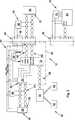
Die in dem landwirtschaftlichen Traktor angeordnete Datenkommunikationsschnittstelle
Zur Vermeidung von unerwünschten Leitungsreflexionen ist das erste Datenkommunikationsnetzwerk
Des Weiteren umfasst die Datenkommunikationsschnittstelle
Der erste Abschlusswiderstand
Die beiden Datenkommunikationsnetzwerke
Dieser ist an einem dritten Leitungsende
Beispielsgemäß handelt es sich bei dem ersten Datenkommunikationsnetzwerk
Der CAN-Datenbus
Genauer gesagt ist der CAN-Datenbus
Terminating Bias Circuit (TBC) ausgebildeten Abschlusswiderstände
Das Ethernet-Datennetz
Beispielsgemäß ist der Schnittstellenstecker
Für die Belange der vorliegenden Erfindung sind die folgenden Pins bzw. Anschlüsse des Implement BUS Breakaway Connector
Der
Aus dem Vorliegen der Gleichspannung ECU_PWR am Steuerpin TBC_DIS des Schnittstellensteckers
In allen anderen Fällen verbleibt die Umschalteinrichtung
Beispielsgemäß werden alle vier zur Verfügung stehenden Leiter des Twisted-Quad-Kabels zum Zwecke der Datenübertragung genutzt, wobei im vorliegenden Fall ein 4-adriges geschirmtes 100BASE_TX Ethernet-Datennetz
ZITATE ENTHALTEN IN DER BESCHREIBUNG QUOTES INCLUDE IN THE DESCRIPTION
Diese Liste der vom Anmelder aufgeführten Dokumente wurde automatisiert erzeugt und ist ausschließlich zur besseren Information des Lesers aufgenommen. Die Liste ist nicht Bestandteil der deutschen Patent- bzw. Gebrauchsmusteranmeldung. Das DPMA übernimmt keinerlei Haftung für etwaige Fehler oder Auslassungen.This list of the documents listed by the applicant has been generated automatically and is included solely for the better information of the reader. The list is not part of the German patent or utility model application. The DPMA assumes no liability for any errors or omissions.
Zitierte PatentliteraturCited patent literature
- DE 102005029405 A1[0002]DE 102005029405 A1[0002]
Zitierte Nicht-PatentliteraturCited non-patent literature
- Standard ISO 11783[0014]Standard ISO 11783[0014]
- Standard ISO 11783-2[0016]Standard ISO 11783-2[0016]
- Standard ISO 11783-2[0017]Standard ISO 11783-2[0017]
- Standard ISO 11783-2[0018]Standard ISO 11783-2[0018]
- IEEE Standard 802.3[0021]IEEE Standard 802.3[0021]
- Standard ISO 11783[0036]Standard ISO 11783[0036]
- Standard ISO 11783-2[0039]Standard ISO 11783-2[0039]
- Standard ISO 11783-2[0040]Standard ISO 11783-2[0040]
- Standard ISO 11783-2[0041]Standard ISO 11783-2[0041]
Claims (6)
Translated fromGermanPriority Applications (5)
| Application Number | Priority Date | Filing Date | Title |
|---|---|---|---|
| DE102011007914ADE102011007914A1 (en) | 2011-04-21 | 2011-04-21 | Data communication interface for an agricultural utility vehicle |
| EP12721782.6AEP2700016B1 (en) | 2011-04-21 | 2012-04-18 | Data communications interface for an agricultural vehicle |
| PCT/EP2012/057072WO2012143389A1 (en) | 2011-04-21 | 2012-04-18 | Data communications interface for an agricultural vehicle |
| JP2014505599AJP2014521538A (en) | 2011-04-21 | 2012-04-18 | Data communication interface for agricultural utility vehicles |
| US14/007,463US9396153B2 (en) | 2011-04-21 | 2012-04-18 | Data communication interface for an agricultural utility vehicle |
Applications Claiming Priority (1)
| Application Number | Priority Date | Filing Date | Title |
|---|---|---|---|
| DE102011007914ADE102011007914A1 (en) | 2011-04-21 | 2011-04-21 | Data communication interface for an agricultural utility vehicle |
Publications (1)
| Publication Number | Publication Date |
|---|---|
| DE102011007914A1true DE102011007914A1 (en) | 2012-10-25 |
Family
ID=46124300
Family Applications (1)
| Application Number | Title | Priority Date | Filing Date |
|---|---|---|---|
| DE102011007914AWithdrawnDE102011007914A1 (en) | 2011-04-21 | 2011-04-21 | Data communication interface for an agricultural utility vehicle |
Country Status (5)
| Country | Link |
|---|---|
| US (1) | US9396153B2 (en) |
| EP (1) | EP2700016B1 (en) |
| JP (1) | JP2014521538A (en) |
| DE (1) | DE102011007914A1 (en) |
| WO (1) | WO2012143389A1 (en) |
Cited By (3)
| Publication number | Priority date | Publication date | Assignee | Title |
|---|---|---|---|---|
| EP2733680A1 (en)* | 2012-11-16 | 2014-05-21 | CLAAS Selbstfahrende Erntemaschinen GmbH | Method for operating a self-propelled harvester |
| DE102015206366A1 (en)* | 2015-04-09 | 2016-10-13 | Deere & Company | Interface device |
| DE102018111767A1 (en)* | 2017-11-10 | 2019-05-16 | Syn Trac Gmbh | Control unit and control system for a combination of a vehicle and an attachment |
Families Citing this family (11)
| Publication number | Priority date | Publication date | Assignee | Title |
|---|---|---|---|---|
| US9008920B1 (en) | 2013-12-05 | 2015-04-14 | Cnh Industrial America Llc | Baler automatic stopping sequence |
| US9717178B1 (en) | 2014-08-08 | 2017-08-01 | The Climate Corporation | Systems and method for monitoring, controlling, and displaying field operations |
| US9526212B2 (en) | 2014-11-26 | 2016-12-27 | Cnh Industrial America Llc | Baler automatic stopping sequence |
| KR101676657B1 (en)* | 2014-12-02 | 2016-11-16 | 현대모비스 주식회사 | Sensor for Vehicle and Vehicle including the same |
| CA3035267C (en) | 2016-08-31 | 2024-06-18 | Vermeer Manufacturing Company | Continuous round baler and improved method of round bale formation |
| US10563774B2 (en) | 2017-06-30 | 2020-02-18 | Intelligent Agricultural Solutions Llc | Sectional control device |
| JP6974194B2 (en)* | 2018-01-25 | 2021-12-01 | 日置電機株式会社 | Bus-side connector, device-side connector and reading system |
| AU2019324566B2 (en)* | 2018-08-23 | 2024-07-11 | Precison Planting Llc | Expandable network architecture for communications between machines and implements |
| US12016257B2 (en) | 2020-02-19 | 2024-06-25 | Sabanto, Inc. | Methods for detecting and clearing debris from planter gauge wheels, closing wheels and seed tubes |
| EP3970474B1 (en)* | 2020-08-27 | 2024-05-15 | AGCO Corporation | Automated tractor speed adjustment for avoidance of plugging a baler |
| CN118743191A (en)* | 2022-03-04 | 2024-10-01 | 采埃孚商用车系统欧洲有限公司 | Bus nodes and plug-in connectors for communication bus systems with bus termination configuration |
Citations (6)
| Publication number | Priority date | Publication date | Assignee | Title |
|---|---|---|---|---|
| US20030090152A1 (en)* | 2000-01-05 | 2003-05-15 | Asko Juntunen | Current distribution system for a vehicle |
| DE19804740C2 (en)* | 1998-02-06 | 2003-12-24 | Josef Rottmeier | Storage device for identification data |
| DE10225888A1 (en)* | 2002-06-11 | 2004-01-08 | Daimlerchrysler Ag | Modular chassis system |
| DE102005029405A1 (en) | 2005-06-24 | 2007-01-11 | Deere & Company, Moline | Tractor-baler combination comprises round baler which is driven by power-take-off on tractor, sensor on baler measuring size of bale and being connected to control unit which regulates engine speed |
| DE112006002894T5 (en)* | 2005-10-21 | 2008-09-18 | Deere & Company, Moline | Networked multi-purpose robotic vehicle |
| DE102007024644A1 (en)* | 2007-05-24 | 2008-11-27 | Deere & Company, Moline | Device for transmitting electrical energy from an agricultural work vehicle to an attachment which can be coupled to the work vehicle |
Family Cites Families (16)
| Publication number | Priority date | Publication date | Assignee | Title |
|---|---|---|---|---|
| WO1991014989A1 (en)* | 1990-03-19 | 1991-10-03 | Thomas Austin Gafford | A repeater/switch for distributed arbitration digital data buses |
| US7478174B2 (en)* | 2002-04-26 | 2009-01-13 | The Boeing Company | Systems and methods for maintaining network stability |
| DE102006008539A1 (en)* | 2006-02-22 | 2007-08-30 | Robert Bosch Gmbh | Error condition simulating method for use in control device, involves connecting circuit points of device to be tested with points of fault generation circuit across multiplexer, and multiplexer is implemented using relay technology |
| US7715433B2 (en) | 2006-07-14 | 2010-05-11 | Boren Gary W | Universal controller and signal monitor |
| JP2008122598A (en)* | 2006-11-10 | 2008-05-29 | Olympus Corp | Microscopic system and extension unit |
| DE102007056318A1 (en)* | 2007-04-12 | 2008-10-16 | Deere & Company, Moline | Communication system of a vehicle and method for operating a communication system |
| US7855573B1 (en)* | 2009-12-14 | 2010-12-21 | Caterpillar Trimble Control Technologies Llc | Controller area network active bus terminator |
| DE102010005658A1 (en)* | 2010-01-19 | 2011-07-21 | THALES Defence Deutschland GmbH, 75175 | Connection module for connecting at least one sensor, actuator or effector to a Service Oriented Architecture (SOA) network |
| DE102010035102A1 (en)* | 2010-08-23 | 2012-04-19 | Bürkert Werke GmbH | Control unit for fluidic systems |
| US8863256B1 (en)* | 2011-01-14 | 2014-10-14 | Cisco Technology, Inc. | System and method for enabling secure transactions using flexible identity management in a vehicular environment |
| US8930066B2 (en)* | 2011-01-21 | 2015-01-06 | Control Solutions LLC | Customizable control apparatus and method for a vehicle turret |
| US8597054B2 (en)* | 2011-03-07 | 2013-12-03 | Schneider Electric It Corporation | CAN bus automatic line termination |
| US8648500B1 (en)* | 2011-05-18 | 2014-02-11 | Xilinx, Inc. | Power supply regulation and optimization by multiple circuits sharing a single supply |
| WO2013074899A1 (en)* | 2011-11-16 | 2013-05-23 | Flextronics Ap, Llc | Configurable dash display |
| DE102011121255B3 (en)* | 2011-12-15 | 2013-04-18 | Lear Corporation Gmbh | Control system for motor vehicle, has control device for extracting and passing HTTP request from controlled area network bus by compatible message onto web server, where bus connects control device and another control device |
| US9020771B1 (en)* | 2014-05-27 | 2015-04-28 | Power Measurements, LLC | Devices and methods for testing the energy measurement accuracy, billing accuracy, functional performance and safety of electric vehicle charging stations |
- 2011
- 2011-04-21DEDE102011007914Apatent/DE102011007914A1/ennot_activeWithdrawn
- 2012
- 2012-04-18JPJP2014505599Apatent/JP2014521538A/enactivePending
- 2012-04-18USUS14/007,463patent/US9396153B2/enactiveActive
- 2012-04-18WOPCT/EP2012/057072patent/WO2012143389A1/enactiveApplication Filing
- 2012-04-18EPEP12721782.6Apatent/EP2700016B1/enactiveActive
Patent Citations (6)
| Publication number | Priority date | Publication date | Assignee | Title |
|---|---|---|---|---|
| DE19804740C2 (en)* | 1998-02-06 | 2003-12-24 | Josef Rottmeier | Storage device for identification data |
| US20030090152A1 (en)* | 2000-01-05 | 2003-05-15 | Asko Juntunen | Current distribution system for a vehicle |
| DE10225888A1 (en)* | 2002-06-11 | 2004-01-08 | Daimlerchrysler Ag | Modular chassis system |
| DE102005029405A1 (en) | 2005-06-24 | 2007-01-11 | Deere & Company, Moline | Tractor-baler combination comprises round baler which is driven by power-take-off on tractor, sensor on baler measuring size of bale and being connected to control unit which regulates engine speed |
| DE112006002894T5 (en)* | 2005-10-21 | 2008-09-18 | Deere & Company, Moline | Networked multi-purpose robotic vehicle |
| DE102007024644A1 (en)* | 2007-05-24 | 2008-11-27 | Deere & Company, Moline | Device for transmitting electrical energy from an agricultural work vehicle to an attachment which can be coupled to the work vehicle |
Non-Patent Citations (3)
| Title |
|---|
| IEEE Standard 802.3 |
| Standard ISO 11783 |
| Standard ISO 11783-2 |
Cited By (4)
| Publication number | Priority date | Publication date | Assignee | Title |
|---|---|---|---|---|
| EP2733680A1 (en)* | 2012-11-16 | 2014-05-21 | CLAAS Selbstfahrende Erntemaschinen GmbH | Method for operating a self-propelled harvester |
| DE102015206366A1 (en)* | 2015-04-09 | 2016-10-13 | Deere & Company | Interface device |
| DE102018111767A1 (en)* | 2017-11-10 | 2019-05-16 | Syn Trac Gmbh | Control unit and control system for a combination of a vehicle and an attachment |
| DE102018111767A8 (en)* | 2017-11-10 | 2019-08-29 | Syn Trac Gmbh | Control unit and control system for a combination of a vehicle and an attachment |
Also Published As
| Publication number | Publication date |
|---|---|
| WO2012143389A1 (en) | 2012-10-26 |
| EP2700016B1 (en) | 2017-07-12 |
| US9396153B2 (en) | 2016-07-19 |
| EP2700016A1 (en) | 2014-02-26 |
| US20140047152A1 (en) | 2014-02-13 |
| JP2014521538A (en) | 2014-08-28 |
Similar Documents
| Publication | Publication Date | Title |
|---|---|---|
| DE102011007914A1 (en) | Data communication interface for an agricultural utility vehicle | |
| DE102010061188B4 (en) | Termination circuit for an active bus of a Controller Area Network | |
| DE102011005088B4 (en) | In-vehicle communication device and in-vehicle communication system in which ECUs contained in a case use an internal bus for mutual communication and an external bus for external communication | |
| DE102013219176B4 (en) | Driver circuit for a digital signal transmission bus | |
| DE102015116800B3 (en) | Input / output module for a bus system | |
| DE102014109206B4 (en) | Sensor interface systems and methods | |
| DE202021100971U1 (en) | Automotive network communication devices and wiring with electromagnetic shielding | |
| DE69915410T2 (en) | Two-standard interface circuit for serial connection | |
| EP1856867B1 (en) | Transceiver with adjustable terminal network for a control device | |
| EP4392792A1 (en) | Device for checking the function of a cable shield of a wired communication connection | |
| DE102005059012B4 (en) | ASI system for connecting several sensors and / or actuators to a controller | |
| DE102016109450A1 (en) | Concept of securing a supply voltage | |
| DE102020115210B4 (en) | Control system for a bus system having at least two transmission lines | |
| DE102010001842B4 (en) | Communication system with signal reflection prevention function and existing nodes in the system | |
| DE10235158A1 (en) | Characteristic wave impedance matching circuit arrangement has matching resistance network between chokes and vehicle data bus line ends for characteristic wave impedance matching of data bus lines | |
| WO2023006260A1 (en) | Coupling circuit for supplying or picking up a direct voltage portion to or on an electrical line wire of a data transmission cable, measuring device for analysing data transmission, signal processing unit and system | |
| DE602004011188T2 (en) | ARRANGEMENT FOR MASS SPREAD COMPENSATION IN A DATA BUSY SYSTEM | |
| DE102015208495A1 (en) | Control electronics for a agricultural or forestry vehicle | |
| DE102016224959A1 (en) | Device for a bus system and method for attenuation of reflections in a data transmission in a bus system | |
| DE10101196A1 (en) | Interface circuit and method for digital signals | |
| DE102016224963A1 (en) | Control device for a bus system and method for data transmission in a bus system | |
| DE102022121235A1 (en) | Vehicle charging communication device for establishing a charging communication connection | |
| DE102016011257A1 (en) | Bus and communication system for DC-free signal transmission on a common medium with termination | |
| DE102007013379B4 (en) | Network termination for connection to a bus line | |
| DE102007052710B4 (en) | Electropneumatic brake control arrangement for a vehicle |
Legal Events
| Date | Code | Title | Description |
|---|---|---|---|
| R163 | Identified publications notified | ||
| R119 | Application deemed withdrawn, or ip right lapsed, due to non-payment of renewal fee |