DE102011002071A1 - System and method for controlling crop overload - Google Patents
System and method for controlling crop overloadDownload PDFInfo
- Publication number
- DE102011002071A1 DE102011002071A1DE102011002071ADE102011002071ADE102011002071A1DE 102011002071 A1DE102011002071 A1DE 102011002071A1DE 102011002071 ADE102011002071 ADE 102011002071ADE 102011002071 ADE102011002071 ADE 102011002071ADE 102011002071 A1DE102011002071 A1DE 102011002071A1
- Authority
- DE
- Germany
- Prior art keywords
- transport vehicle
- loading container
- harvester
- crop
- control unit
- Prior art date
- Legal status (The legal status is an assumption and is not a legal conclusion. Google has not performed a legal analysis and makes no representation as to the accuracy of the status listed.)
- Withdrawn
Links
- 238000000034methodMethods0.000titleclaimsdescription15
- 238000012546transferMethods0.000claimsabstractdescription28
- 238000003306harvestingMethods0.000claimsabstractdescription14
- 238000001514detection methodMethods0.000claimsabstractdescription9
- 239000004459forageSubstances0.000claimsdescription23
- 238000013459approachMethods0.000claimsdescription3
- 230000003287optical effectEffects0.000claimsdescription3
- 230000000875corresponding effectEffects0.000description5
- 238000011156evaluationMethods0.000description5
- 241001124569LycaenidaeSpecies0.000description3
- 230000001276controlling effectEffects0.000description3
- 230000001419dependent effectEffects0.000description2
- 238000013461designMethods0.000description2
- 238000011161developmentMethods0.000description2
- 230000000694effectsEffects0.000description2
- KEUKAQNPUBYCIC-UHFFFAOYSA-Nethaneperoxoic acid;hydrogen peroxideChemical compoundOO.CC(=O)OOKEUKAQNPUBYCIC-UHFFFAOYSA-N0.000description2
- 238000005429filling processMethods0.000description2
- 238000010191image analysisMethods0.000description2
- BUHVIAUBTBOHAG-FOYDDCNASA-N(2r,3r,4s,5r)-2-[6-[[2-(3,5-dimethoxyphenyl)-2-(2-methylphenyl)ethyl]amino]purin-9-yl]-5-(hydroxymethyl)oxolane-3,4-diolChemical compoundCOC1=CC(OC)=CC(C(CNC=2C=3N=CN(C=3N=CN=2)[C@H]2[C@@H]([C@H](O)[C@@H](CO)O2)O)C=2C(=CC=CC=2)C)=C1BUHVIAUBTBOHAG-FOYDDCNASA-N0.000description1
- SEPPVOUBHWNCAW-FNORWQNLSA-N(E)-4-oxonon-2-enalChemical compoundCCCCCC(=O)\C=C\C=OSEPPVOUBHWNCAW-FNORWQNLSA-N0.000description1
- LLBZPESJRQGYMB-UHFFFAOYSA-N4-oneNatural productsO1C(C(=O)CC)CC(C)C11C2(C)CCC(C3(C)C(C(C)(CO)C(OC4C(C(O)C(O)C(COC5C(C(O)C(O)CO5)OC5C(C(OC6C(C(O)C(O)C(CO)O6)O)C(O)C(CO)O5)OC5C(C(O)C(O)C(C)O5)O)O4)O)CC3)CC3)=C3C2(C)CC1LLBZPESJRQGYMB-UHFFFAOYSA-N0.000description1
- 230000000454anti-cipatory effectEffects0.000description1
- 230000005540biological transmissionEffects0.000description1
- 230000000977initiatory effectEffects0.000description1
- 238000012545processingMethods0.000description1
- 230000035484reaction timeEffects0.000description1
- 238000001454recorded imageMethods0.000description1
- 230000003319supportive effectEffects0.000description1
Images

Classifications
- A—HUMAN NECESSITIES
- A01—AGRICULTURE; FORESTRY; ANIMAL HUSBANDRY; HUNTING; TRAPPING; FISHING
- A01D—HARVESTING; MOWING
- A01D43/00—Mowers combined with apparatus performing additional operations while mowing
- A01D43/06—Mowers combined with apparatus performing additional operations while mowing with means for collecting, gathering or loading mown material
- A01D43/07—Mowers combined with apparatus performing additional operations while mowing with means for collecting, gathering or loading mown material in or into a trailer
- A01D43/073—Mowers combined with apparatus performing additional operations while mowing with means for collecting, gathering or loading mown material in or into a trailer with controllable discharge spout
- A—HUMAN NECESSITIES
- A01—AGRICULTURE; FORESTRY; ANIMAL HUSBANDRY; HUNTING; TRAPPING; FISHING
- A01D—HARVESTING; MOWING
- A01D43/00—Mowers combined with apparatus performing additional operations while mowing
- A01D43/08—Mowers combined with apparatus performing additional operations while mowing with means for cutting up the mown crop, e.g. forage harvesters
- A01D43/086—Mowers combined with apparatus performing additional operations while mowing with means for cutting up the mown crop, e.g. forage harvesters and means for collecting, gathering or loading mown material
- A01D43/087—Mowers combined with apparatus performing additional operations while mowing with means for cutting up the mown crop, e.g. forage harvesters and means for collecting, gathering or loading mown material with controllable discharge spout
Landscapes
- Life Sciences & Earth Sciences (AREA)
- Environmental Sciences (AREA)
- Harvester Elements (AREA)
- Harvesting Machines For Specific Crops (AREA)
- Guiding Agricultural Machines (AREA)
- Agricultural Machines (AREA)
Abstract
Translated fromGermanDescription
Translated fromGermanDie Erfindung betrifft ein System zur Steuerung der Erntegutüberladung von einer selbstfahrenden landwirtschaftlichen Erntemaschine in den Ladebehälter eines Transportfahrzeugs, umfassend eine der Erntemaschine zugeordnete Überladeeinrichtung, aus der Erntegut in Form eines Erntegutstrahls austritt, und eine Erkennungseinrichtung, welche die relative Lage des Ladebehälters gegenüber der Erntemaschine ermittelt und an eine Steuereinheit übermittelt, wobei die Steuereinheit zumindest einen der Überladeeinrichtung zugeordneten Aktor derart betätigt, dass der Erntegutstrahl innerhalb des Ladebehälters auftrifft, um diesen mit Erntegut zu befüllen.The invention relates to a system for controlling the Erntegutüberladung of a self-propelled agricultural harvester in the loading container of a transport vehicle, comprising a harvester associated with the unloading, exits the crop in the form of Erntegutstrahls, and a detection device which determines the relative position of the loading container relative to the harvester and transmitted to a control unit, wherein the control unit actuates at least one of the transfer device associated actuator such that the Erntegutstrahl impinges within the loading container to fill it with crop.
Selbstfahrende landwirtschaftliche Erntemaschinen wie Feldhäcksler sind mit einer Überladeeinrichtung ausgestattet, die aufgrund ihrer Funktion und Form auch als Auswurfkrümmer bezeichnet wird. Diese dient dazu, während der Erntefahrt geerntetes Gut, das die inneren Bearbeitungs- und Förderaggregate (Einzugswalzen, Häckseltrommel, Korn-Cracker, Nachbeschleuniger) des Feldhäckslers durchlaufen hat, in Form eines Erntegutstrahls in einen mitfahrenden Ladebehälter zu überladen. Der Ladebehälter kann sich auf einem Anhänger befinden, der wiederum von einem Transportfahrzeug (z. B. einem Traktor) gezogen wird, oder kann Teil eines selbstfahrenden Transportfahrzeugs (z. B. eines Lastwagens) sein.Self-propelled agricultural harvesters such as forage harvesters are equipped with a transfer device, which is also referred to as a chute due to their function and shape. This serves to over-harvest crops harvested during harvesting, which has passed through the internal processing and delivery units (feed rollers, chopper drum, grain cracker, post accelerator) of the forage harvester in the form of a Erntegutstrahls in a moving loading container. The cargo box may be on a trailer, which in turn is towed by a transport vehicle (eg, a tractor), or may be part of a self-propelled transport vehicle (eg, a truck).
Da sich der Feldhäcksler und das Transportfahrzeug während des Überladevorgangs mit nicht unerheblicher Geschwindigkeit über das Feld bewegen und allein schon durch Bodenunebenheiten und dadurch bedingte Spurabweichungen der fahrenden Maschinen eine absolute Parallelfahrt von Feldhäcksler und Transportfahrzeug praktisch ausgeschlossen ist, ist es zur Gewährleistung einer verlustarmen Überladung des Ernteguts erforderlich, dass sich der Überladekrümmer mittels mehrerer Aktoren unterschiedlich ausrichten lässt, um auf diese Weise den austretenden Erntegutstrahl so zu lenken, dass dieser innerhalb des Ladebehälters auftrifft. Derartige Aktoren umfassen zumeist einen Drehantrieb des Überladekrümmers um eine bezogen auf den Feldhäcksler vertikale Achse, eine Höhenverstellung des Überladekrümmers um eine bezogen auf den Feldhäcksler horizontale Achse und eine durch eine verstellbare Klappe am auswurfseitigen Ende des Auswurfkrümmers realisierte Abwurfwinkelverstellung.Since the forage harvester and the transport vehicle move during the transfer process at a considerable speed over the field and just by bumps and consequent lane deviations of moving machines an absolute parallel drive of forage harvester and transport vehicle is virtually impossible, it is to ensure low-loss overloading of the crop Required that the Überladekrümmer can be aligned differently by means of several actuators, so as to direct the exiting Erntegutstrahl so that it impinges within the loading container. Such actuators usually comprise a rotary drive of the transfer chute about a relative to the forage harvester vertical axis, a height adjustment of the transfer chute to a relative to the forage harvester horizontal axis and a realized by an adjustable flap on the discharge end of the chute throw-off angle adjustment.
Aufgrund steigender Erntegutdurchsätze bei Feldhäckslern erhöhen sich die Anforderungen an den Überladevorgang ständig, da wegen der höheren Durchsatzleistung eine Befüllung eines Ladebehälters gleichen Volumens in immer kürzerer Zeit stattfindet. Eine präzise Ausrichtung des Erntegutstrahls ist wesentliche Voraussetzung, um dies zu ermöglichen. Wegen hoher Fahrgeschwindigkeiten auf dem Feld ist eine manuelle Ausrichtung der Überladeeinrichtung für den Fahrer eines Feldhäckslers mühsam.Due to increasing crop throughputs in forage harvesters, the requirements for the transfer process are constantly increasing, because due to the higher throughput, filling of a loading container of the same volume takes place in ever shorter time. A precise alignment of the Erntegutstrahls is essential to enable this. Because of high speeds on the field, a manual alignment of the transfer device for the driver of a forage harvester is cumbersome.
Die
Vorraussetzung für das System gemäß
Es ist eine Aufgabe der vorliegenden Erfindung, ein System der eingangs genannten Art anzugeben, welches die Fahrer des Transportfahrzeugs und der Erntemaschine stärker von der Beobachtung des Überladevorgangs entlastet. Weiterhin soll ein dementsprechendes Verfahren angegeben werden.It is an object of the present invention to provide a system of the type mentioned, which relieves the driver of the transport vehicle and the harvester stronger from the observation of the overcharge. Furthermore, a corresponding method should be specified.
Zur Lösung wird ein System gemäß den Merkmalen des Anspruchs 1 vorgeschlagen.To solve a system according to the features of
Erfindungsgemäß ist demnach die Steuereinheit, welche die Ansteuerung der Aktoren der Überladeeinrichtung – und damit die Ausrichtung des Erntegutstrahls – vornimmt, betreibbar, für das Transportfahrzeug ein Steuersignal zu generieren, das eine zum Überladen in den Ladebehälter geeignete Relativposition des Transportfahrzeugs gegenüber der Erntemaschine vorgibt. Dem erfindungsgemäßen System liegt die Erkenntnis zugrunde, dass für eine verlustarme selbständige Steuerung des Befüllvorgangs des Ladebehälters zwei Prozesse dynamisch auf geeignete Weise zusammenwirken müssen. Dies ist zunächst die Ausrichtung des Erntegutstrahls, welche sich durch Betätigung der Aktoren der Überladeeinrchtung kurzfristig beeinflussen lässt.According to the invention, therefore, the control unit, which controls the actuators of the transfer device - and thus the alignment of the Erntegutstrahls - operable to generate a control signal for the transport vehicle, which specifies a suitable for overloading in the loading container relative position of the transport vehicle relative to the harvester. The system according to the invention is based on the finding that for a low-loss, independent control of the filling process of the loading container, two processes must interact dynamically in a suitable manner. This is initially the orientation of the Erntegutstrahls, which can be influenced in the short term by actuation of the actuators Überladeeinrchtung.
Daneben ist zugleich die Bereitstellung des Ladebehälters in einer geeigneten Relativposition zur Erntemaschine erforderlich. Dieser zweite Prozess hat gegenüber der Ausrichtung des Erntegutstrahls eine deutlich höhere Reaktionszeit. Indem die Steuereinheit, welche durch Ausrichtung der Überladeeinrichtung den Erntegutstrahl innerhalb der konstruktionsbedingten Grenzen in den Ladebehälter richtet, daneben ein an das Transportfahrzeug gerichtetes Steuersignal generiert, das eine für das Überladen in den Ladebehälter geeignete Relativposition des Transportfahrzeugs vorgibt, wird erfindungsgemäß ein System geschaffen, das die eingangs genannte Aufgabe vorteilhaft löst und die beiden Prozesse günstig miteinander verknüpft, um Überladeverluste zu vermeiden und die Fahrer zu entlasten. In addition, at the same time the provision of the loading container in a suitable relative position to the harvesting machine is required. This second process has a much higher reaction time than the orientation of the crop jet. By the control unit, which directs the Erntegutstrahl within the design limits in the loading container by aligning the Erntegutstrahl, next to a directed to the transport vehicle control signal that specifies a suitable for overcharging in the loading container relative position of the transport vehicle, a system is provided according to the invention solves the aforementioned object advantageous and the two processes linked together favorably to avoid Überladeverluste and relieve the driver.
Gemäß einer einfachen Weiterbildung des Systems kann das Steuersignal in einer für einen Fahrer des Transportfahrzeugs wahrnehmbaren Form ausgegeben werden. Beispielsweise könnte auf einer für den Fahrer des Transportfahrzeugs sichtbaren Anzeige eine Steueranweisung ausgegeben werden. Die Ausgabe könnte gleichermaßen akustisch über einen Lautsprecher erfolgen. Diese könnte eine Geschwindigkeitsvorgabe und/oder eine Lenkangabe umfassen. Eine derartige Signalausgabe an den Fahrer bietet den Vorteil, dass der Fahrer eine unterstützende präzise Fahranweisung erhält, gleichwohl aber noch frei entscheiden kann, ob bzw. inwieweit er dieser Anweisung folgt.According to a simple further development of the system, the control signal can be output in a form perceptible to a driver of the transport vehicle. For example, a control instruction could be issued on a display visible to the driver of the transport vehicle. The output could equally be acoustically via a loudspeaker. This could include a speed specification and / or a steering indication. Such a signal output to the driver has the advantage that the driver receives a supportive precise driving instruction, but nevertheless can freely decide whether or to what extent he follows this instruction.
Zur Erhöhung des Komforts und zur weiteren Entlastung des Fahrers geht in bevorzugter Weise das Steuersignal in einen dem Transportfahrzeug zugeordneten Fahrregler ein, welcher das Transportfahrzeug selbsttätig gegenüber der Erntemaschine positioniert. Durch diese Maßnahme wird somit – je nach Umsetzungsgrad – eine teil- oder vollautonome, an den Überladevorgang angepasste Fahrregelung des Transportfahrzeugs geschaffen, wobei im Ergebnis die selbstfahrende Erntemaschine als Leitfahrzeug das Transportfahrzeug mitsteuert.In order to increase the comfort and to further relieve the driver, the control signal is preferably input into a travel controller assigned to the transport vehicle, which autonomously positions the transport vehicle in relation to the harvesting machine. By this measure is thus - depending on the degree of implementation - a partially or fully autonomous, adapted to the Überladevorgang control of the transport vehicle created, as a result, the self-propelled harvester mitsteuert as a leader vehicle, the transport vehicle.
Dabei kann das Steuersignal eine vom Transportfahrzeug zu erreichende Fahrgeschwindigkeit und/oder einen vom Transportfahrzeug einzunehmenden Lenkwinkel beinhalten.In this case, the control signal may include a vehicle speed to be reached by the transport vehicle and / or a steering angle to be taken by the transport vehicle.
Gemäß einer bevorzugten Weiterbildung der Erfindung wirkt die Steuereinheit einer Annäherung des Überladevorgangs an einen kritischen Zustand durch ein geeignetes Steuersignal an das Transportfahrzeug entgegen. Durch diese Maßnahme kann beispielsweise gewährleistet werden, dass während der Erntegutüberladung dem Erreichen einer Endlage der Überladeeinrichtung, dem Erreichen einer Außengrenze des Ladebehälters und/oder dem Erreichen einer maximalen Befüllhöhe durch eine Anpassung der Relativposition des Ladebehälters an die veränderte Überladebedingung entgegengewirkt wird. Eine solche Anpassung der Relativposition wird vorzugsweise rechtzeitig – d. h. vorausschauend, nämlich vor Erreichen des kritischen Zustands – durch die Steuereinheit eingeleitet, so dass der Überladevorgang verlust- bzw. unterbrechungsfrei fortgeführt werden kann.According to a preferred embodiment of the invention, the control unit counteracts an approach of the transfer operation to a critical state by a suitable control signal to the transport vehicle. By this measure, it can be ensured, for example, that counteracts the achievement of an end position of the transfer device, reaching an outer limit of the loading container and / or the achievement of a maximum filling height by adjusting the relative position of the loading container to the changed Überladebonditionung during Erntegutüberladung. Such an adjustment of the relative position is preferably timely - d. H. anticipatory, namely before reaching the critical state - initiated by the control unit, so that the Überladevorgang loss or can be continued without interruption.
Entsprechende Sensoren zur Erkennung des jeweiligen kritischen Zustands sind zweckmäßig. Im Fall des Erreichens von Endlagen der Überladeeinrichtung können dies den Aktoren der Überladeeinrichtung zugeordnete Weg- oder Winkelsensoren sein. Vor Erreichen einer mittels der Sensoren erkannten Endlage leitet die Steuereinheit dabei eine Relativpositionsänderung des Transportfahrzeugs ein, um den Überladevorgang nicht durch das Erreichen der drohenden Endlage zu gefährden.Corresponding sensors for detecting the respective critical state are expedient. In the case of reaching end positions of the transfer device, this may be the path or angle sensors associated with the actuators of the transfer device. Before reaching an end position detected by means of the sensors, the control unit initiates a relative position change of the transport vehicle in order not to jeopardize the overcharge by reaching the impending end position.
Gemäß einer weiteren vorteilhaften Ausgestaltung ist ein Sensor, bevorzugt in Form einer geeignet ausgerichteten Kamera, vorgesehen, der zur Erfassung eines Auftreffpunkts des Erntegutstrahls geeignet ist, wobei der kritische Zustand dann besteht, dass der Auftreffpunkt außerhalb des Ladebehälters liegt. Die Steuereinheit erkennt gemäß dieser Ausgestaltung, ob der Erntegutstrahl den Ladebehälter zu verlassen droht und leitet vorausschauend eine Relativpositionsänderung des Transportfahrzeugs ein.According to a further advantageous embodiment, a sensor, preferably in the form of a suitably oriented camera, is provided, which is suitable for detecting a point of impact of the Erntegutstrahls, wherein the critical condition is then that the point of impact is outside the loading container. The control unit recognizes according to this embodiment, whether the Erntegutstrahl threatens to leave the loading container and initiates forward a relative position change of the transport vehicle.
Zur Feststellung, ob der Auftreffpunkt außerhalb oder innerhalb des Ladebehälters liegt, kann vorteilhaft ein Sensor vorgesehen sein, der zur Erfassung von Außenrändern des Ladebehälters geeignet ist. Die Steuereinheit kann so durch Positionsvergleich von Auftreffpunkt und Außenrand beurteilen, ob bzw. wo der Erntegutstrahl den Behälter trifft. Bei diesem Sensor kann es sich vorteilhaft ebenfalls um eine Kamera handeln. Bevorzugt ist dies dieselbe Kamera, die auch den Auftreffpunkt erfasst.In order to determine whether the point of impact is outside or inside the loading container, a sensor may be advantageously provided which is suitable for detecting outer edges of the loading container. The control unit can thus assess by position comparison of impact point and outer edge, whether or where the Erntegutstrahl hits the container. This sensor can advantageously also be a camera. This is preferably the same camera that also detects the point of impact.
Ergänzend oder alternativ ist vorteilhaft ein Sensor vorgesehen, der zur Erfassung des Befüllzustands des Ladebehälters geeignet ist, wobei der kritische Zustand im Erreichen eines maximalen Befüllzustands besteht. Besonders vorteilhaft kann ein derartiger Sensor zwischen verschiedenen positionsabhängigen Befüllzuständen auf dem Ladebehälter unterscheiden. Handelt es sich bei dem Sensor um eine Kamera, so kann eine positionsabhängige Befüllzustandsunterscheidung beispielsweise durch entsprechende Bildauswertung erfolgen. Die Steuereinheit kann so bei Erreichen einer maximalen Füllhöhe an einer Position des Ladebehälters durch Einleiten einer Relativpositionsänderung des Transportfahrzeugs den Ladebehälter an anderer Position weiterbefüllen.Additionally or alternatively, a sensor is advantageously provided, which is suitable for detecting the Befüllzustands of the cargo container, wherein the critical state is to achieve a maximum Befüllzustands. Particularly advantageously, such a sensor can distinguish between different position-dependent filling states on the loading container. If the sensor is a camera, then a position-dependent fill state distinction can be made, for example, by appropriate image evaluation. The control unit can then continue to fill the loading container at another position upon reaching a maximum filling level at a position of the loading container by initiating a relative position change of the transport vehicle.
Gemäß einer vorteilhaften Weiterbildung der Erfindung berücksichtigt die Steuereinheit bei der Erzeugung des an das Transportfahrzeug gerichteten Steuersignals eine Befüllstrategie, die bevorzugt durch den Maschinenbediener auswählbar ist. Eine Befüllstrategie kann beispielsweise darin bestehen, den Ladebehälter von vorn nach hinten (oder umgekehrt) zu befüllen. According to an advantageous embodiment of the invention, the control unit takes into account in the generation of the control signal directed to the transport vehicle, a filling strategy, which is preferably selectable by the machine operator. A filling strategy may be, for example, filling the loading container from front to back (or vice versa).
Es kann sich bei der Überladeeinrichtung grundsätzlich um eine beliebig gestaltete Einrichtung handeln, die sich zur Ausbringung eines Erntegutstrahls eignet. Dementsprechend können unterschiedlichste Aktoren verwendet werden, um den Erntegutstrahl auszurichten. Insbesondere im Fall eines für Feldhäcksler üblichen Auswurfkrümmers handelt es sich bei dem zumindest einen der Überladeeinrichtung zugeordneten Aktor um einen Aktor zur Höhensteuerung der Überladeeinrichtung, einen Aktor zur Drehung der Überladeeinrichtung und einen Aktor zur Klappensteuerung der Überladeeinrichtung. Zusätzlich kann ein Aktor zur Spaltweitenverstellung am Nachbeschleuniger und/oder ein beliebiger bauartbedingter sonstiger den Auftreffpunkt beeinflussender Aktor berücksichtigt werden.In principle, the transfer device can be an arbitrarily designed device which is suitable for delivering a crop stream. Accordingly, a wide variety of actuators can be used to align the Erntegutstrahl. In particular, in the case of a usual for forage harvester discharge elbow is at least one of the transfer device associated actuator to an actuator for height control of the transfer device, an actuator for rotating the transfer device and an actuator for flap control of the transfer device. In addition, an actuator for gap width adjustment on the post-accelerator and / or any design-related other influencing the impact point actuator can be considered.
Als Erkennungseinrichtung zur Ermittlung der relativen Lage des Ladebehälters gegenüber der Erntemaschine sind unterschiedliche Einrichtungen denkbar. Bevorzugt weist die Erkennungseinrichtung einen optischen Sensor beispielsweise in Form einer Kamera auf. Eine derartige Kamera kann beispielsweise an der Erntemaschine, insbesondere an der Überladeeinrichtung angeordnet und so ausgerichtet sein, dass diese den Ladebehälter zumindest bereichsweise optisch erfasst. Mittels einer elektronischen Bildauswertung erfolgt dann die Ermittlung der relativen Lage, wobei im Fall einer Anbringung der Kamera an der (beweglichen) Überladeeinrichtung die Stellung der Überladeeinrichtung zu berücksichtigen ist. Andere Anbringungsmöglichkeiten von Kameras zur Ermittlung der relativen Lage sind denkbar. So könnte alternativ oder ergänzend eine Kamera am Transportfahrzeug oder am Ladebehälter angeordnet sein, die beispielsweise einen oder mehrere Referenzpunkte an der Erntemaschine optisch erfasst. Durch entsprechende Bildauswertung ließe sich auch daraus die relative Lage des Ladebehälters ermitteln.As a detection device for determining the relative position of the cargo container relative to the harvester different devices are conceivable. The identification device preferably has an optical sensor, for example in the form of a camera. Such a camera can be arranged, for example, on the harvesting machine, in particular on the transfer device, and aligned in such a way that it optically captures the loading container at least in regions. By means of an electronic image evaluation then the determination of the relative position, wherein in the case of attachment of the camera to the (mobile) transfer device, the position of the transfer device is to be considered. Other attachment possibilities of cameras for determining the relative position are conceivable. Thus, alternatively or additionally, a camera could be arranged on the transport vehicle or on the loading container, which optically detects, for example, one or more reference points on the harvesting machine. The relative position of the loading container could also be determined by appropriate image analysis.
Die Verwendung eines Systems aus mehreren Kameras, welche eine Erfassung unterschiedlicher Perspektiven vornehmen, kann die allgemein Genauigkeit der Bildauswertung und damit der Relativpositionsermittlung erhöhen. Vorteilhaft kommt eine 3-D-Kamera oder ein Profil eines Laserscanners zum Einsatz.The use of a system of several cameras, which make a detection of different perspectives, can increase the overall accuracy of the image analysis and thus the relative position determination. Advantageously, a 3-D camera or a profile of a laser scanner is used.
Gemäß einer alternativen oder ergänzenden Weiterbildung der Erfindung ist es denkbar, eine Erkennungseinrichtung zu verwenden, die geeignet ist, die relative Lage des Ladebehälters durch den Vergleich von Positionsdaten der Erntemaschine mit Positionsdaten des Ladebehälters oder des Transportfahrzeugs zu ermitteln. Dazu können Erntemaschine und Transportfahrzeug bzw. Ladebehälter mit Navigationseinheiten ausgestattet sein, welche deren Positionen per Funk austauschen.According to an alternative or additional development of the invention, it is conceivable to use a detection device which is suitable for determining the relative position of the loading container by comparing position data of the harvesting machine with position data of the loading container or the transport vehicle. For this harvester and transport vehicle or cargo container can be equipped with navigation units which exchange their positions by radio.
Das erfindungsgemäße System eignet sich zur Steuerung der Erntegutüberladung von selbstfahrenden Erntemaschinen. Bevorzugt handelt es sich dabei um einen Feldhäcksler oder Mähdrescher.The system according to the invention is suitable for controlling the crop overload of self-propelled harvesting machines. This is preferably a forage harvester or combine harvester.
Weiterhin wird zur Lösung der eingangs genannten Aufgabe ein Verfahren mit den Merkmalen des Anspruchs 14 vorgeschlagen. Das Verfahren gemäß Anspruch 14 erzielt dem System gemäß Anspruch 1 entsprechende Wirkungen, weshalb auf die dortigen entsprechend anzuwendenden Ausführungen verwiesen wird.Furthermore, a method having the features of
Die Erfindung wird im Folgenden unter Hinweis auf die beigefügten Figuren anhand eines Ausführungsbeispiels näher erläutert. Daraus ergeben sich auch weitere Einzelheiten und Vorteile der Erfindung. Es zeigen:The invention will be explained in more detail below with reference to the attached figures using an exemplary embodiment. This also results in further details and advantages of the invention. Show it:
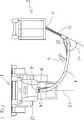
Unter anderem zur Beeinflussung der Lage des Auftreffpunkts P auf den Ladebehälter
Am Auswurfkrümmer
Die Funktionsweise einschließlich der erzielten Effekte wird im Folgenden anhand
Zusätzlich zur Darstellung gemäß
Gemäß
Die Steuereinheit
Während der Befüllung beobachtet die Kamera
Das so beschriebene Überladen kann nur zuverlässig stattfinden, wenn sich der Ladebehälter
Das erfindungsgemäße System bzw. Verfahren löst dieses Problem dadurch, dass die Steuereinheit
Im gezeigten Ausführungsbeispiel wird die relative Lage des Ladebehälters
Im Ergebnis wird bei dem beschriebenen System bzw. Verfahren die verhältnismäßig schnell reagierende Regelung des Auswurfkrümmers
BezugszeichenlisteLIST OF REFERENCE NUMBERS
- 11
- FeldhäckslerForage
- 22
- Ladebehälterloading container
- 33
- Transportfahrzeugtransport vehicle
- 44
- Auswurfkrümmerchute
- 55
- Erntegutstrahlcrop discharge flow
- 66
- Kameracamera
- 77
- Steuereinheitcontrol unit
- 88th
- Drehantrieb KrümmerRotary drive manifold
- 99
- Hubzylinder KrümmerLift cylinder manifold
- 1010
- KlappenstellzylinderFlap actuator cylinder
- 1111
- Fahrreglerthrottle
- 1212
- Maschinenrahmenmachine frame
- 1313
- vertikale Schwenkachsevertical pivot axis
- 1414
- horizontale Schwenkachsehorizontal swivel axis
- PP
- Auftreffpunktof impact
- SS
- Steuersignalcontrol signal
- FRFR
- Fahrtrichtungdirection of travel
ZITATE ENTHALTEN IN DER BESCHREIBUNG QUOTES INCLUDE IN THE DESCRIPTION
Diese Liste der vom Anmelder aufgeführten Dokumente wurde automatisiert erzeugt und ist ausschließlich zur besseren Information des Lesers aufgenommen. Die Liste ist nicht Bestandteil der deutschen Patent- bzw. Gebrauchsmusteranmeldung. Das DPMA übernimmt keinerlei Haftung für etwaige Fehler oder Auslassungen.This list of the documents listed by the applicant has been generated automatically and is included solely for the better information of the reader. The list is not part of the German patent or utility model application. The DPMA assumes no liability for any errors or omissions.
Zitierte PatentliteraturCited patent literature
- EP 2020174 A1[0005, 0006]EP 2020174 A1[0005, 0006]
Claims (16)
Translated fromGermanPriority Applications (5)
| Application Number | Priority Date | Filing Date | Title |
|---|---|---|---|
| DE102011002071ADE102011002071A1 (en) | 2011-04-15 | 2011-04-15 | System and method for controlling crop overload |
| EP12151017.6AEP2510775B1 (en) | 2011-04-15 | 2012-01-13 | Method and system for controlling the transfer of harvested goods |
| US13/417,495US20120263560A1 (en) | 2011-04-15 | 2012-03-12 | System and method for controlling crop transfer |
| ARP120101071AAR085746A1 (en) | 2011-04-15 | 2012-03-29 | PROCEDURE SYSTEM TO CONTROL THE LOAD TRANSFER OF HARVESTED PRODUCT |
| RU2012113130/13ARU2583680C2 (en) | 2011-04-15 | 2012-04-05 | System and method of managing overload of picked mass |
Applications Claiming Priority (1)
| Application Number | Priority Date | Filing Date | Title |
|---|---|---|---|
| DE102011002071ADE102011002071A1 (en) | 2011-04-15 | 2011-04-15 | System and method for controlling crop overload |
Publications (1)
| Publication Number | Publication Date |
|---|---|
| DE102011002071A1true DE102011002071A1 (en) | 2012-10-18 |
Family
ID=45531205
Family Applications (1)
| Application Number | Title | Priority Date | Filing Date |
|---|---|---|---|
| DE102011002071AWithdrawnDE102011002071A1 (en) | 2011-04-15 | 2011-04-15 | System and method for controlling crop overload |
Country Status (5)
| Country | Link |
|---|---|
| US (1) | US20120263560A1 (en) |
| EP (1) | EP2510775B1 (en) |
| AR (1) | AR085746A1 (en) |
| DE (1) | DE102011002071A1 (en) |
| RU (1) | RU2583680C2 (en) |
Cited By (3)
| Publication number | Priority date | Publication date | Assignee | Title |
|---|---|---|---|---|
| DE102018005678A1 (en) | 2018-07-19 | 2020-01-23 | Hochschule Anhalt | harvester |
| EP3970471A1 (en) | 2020-09-21 | 2022-03-23 | CLAAS E-Systems GmbH | Method for controlling overloading of harvested material |
| DE102020124508A1 (en) | 2020-09-21 | 2022-03-24 | Claas E-Systems Gmbh | Crop overload control method |
Families Citing this family (98)
| Publication number | Priority date | Publication date | Assignee | Title |
|---|---|---|---|---|
| US9607342B2 (en) | 2011-07-18 | 2017-03-28 | Conservis Corporation | GPS-based ticket generation in harvest life cycle information management system and method |
| US9881278B2 (en) | 2011-07-18 | 2018-01-30 | Conservis Corporation | Ticket-based harvest life cycle information management: system and method |
| US20130024330A1 (en) | 2011-07-18 | 2013-01-24 | Conservis Corp. | Ticket Based Harvest Management System and Method |
| US9392746B2 (en) | 2012-02-10 | 2016-07-19 | Deere & Company | Artificial intelligence for detecting and filling void areas of agricultural commodity containers |
| US9861040B2 (en) | 2012-02-10 | 2018-01-09 | Deere & Company | Method and stereo vision system for facilitating the unloading of agricultural material from a vehicle |
| WO2013162673A2 (en)* | 2012-02-10 | 2013-10-31 | Deere & Company | System and method of material handling using one or more imaging devices on the transferring vehicle to control the material distribution into the storage portion of the receiving vehicle |
| JP5411976B1 (en)* | 2012-09-21 | 2014-02-12 | 株式会社小松製作所 | Work vehicle periphery monitoring system and work vehicle |
| EP2743768B1 (en)* | 2012-12-14 | 2019-03-06 | CLAAS Tractor S.A.S. | Optical system for an agricultural machine |
| CA2911502C (en)* | 2013-03-15 | 2021-03-02 | Conservis Corporation | Ticket-based harvest management system and method |
| US9481281B2 (en)* | 2013-04-11 | 2016-11-01 | Dp Techlink, Llc | Transport assembly locking system |
| DE102013012026A1 (en)* | 2013-07-19 | 2015-01-22 | Claas Selbstfahrende Erntemaschinen Gmbh | Vehicle network, apparatus and method for its coordination |
| DE102013012027A1 (en)* | 2013-07-19 | 2015-01-22 | Claas Selbstfahrende Erntemaschinen Gmbh | Self-propelled harvester and vehicle network |
| GB2517049B (en)* | 2013-07-28 | 2019-09-11 | Deere & Co | Artificial intelligence for detecting and filling void areas of agricultural commodity containers |
| BE1021104B1 (en)* | 2013-08-13 | 2016-01-12 | Cnh Industrial Belgium Nv | HARVESTER FOR USE IN AGRICULTURE THAT DISCHARGES THROUGH THE MOWER STRUCTURE. |
| BE1021106B1 (en) | 2013-09-03 | 2016-03-15 | Cnh Industrial Belgium Nv | DISCHARGING DEVICES FOR HARVESTERS FOR USE IN AGRICULTURE |
| BE1021108B1 (en)* | 2013-10-28 | 2016-01-18 | Cnh Industrial Belgium Nv | DISCHARGE SYSTEMS |
| BE1021164B1 (en)* | 2013-10-28 | 2016-01-18 | Cnh Industrial Belgium Nv | DISCHARGE SYSTEMS |
| BE1021167B1 (en) | 2013-12-10 | 2016-01-14 | Cnh Industrial Belgium Nv | SENSOR SETUP |
| DE102014100136A1 (en) | 2014-01-08 | 2015-07-09 | Claas Selbstfahrende Erntemaschinen Gmbh | harvester |
| DE102014216603B4 (en)* | 2014-08-21 | 2018-02-22 | Wirtgen Gmbh | Self-propelled milling machine, as well as method for unloading milled material |
| WO2016079580A1 (en)* | 2014-11-19 | 2016-05-26 | Agco Corporation | Unloading conveyor swing control system |
| US10834872B2 (en)* | 2015-07-02 | 2020-11-17 | Cnh Industriall America Llc | Unload spout inclination limit adjust system and method |
| US10015928B2 (en) | 2015-08-10 | 2018-07-10 | Deere & Company | Method and stereo vision system for managing the unloading of an agricultural material from a vehicle |
| EP3150052B1 (en) | 2015-09-30 | 2018-06-13 | CLAAS E-Systems KGaA mbH & Co KG | Crop harvesting machine |
| CN108473260B (en)* | 2016-01-21 | 2022-08-12 | 维特根有限公司 | System comprising construction machine, transport vehicle with loading space and image recording device and method for displaying image stream during loading or unloading of transport vehicle |
| EP3315005B1 (en)* | 2016-10-28 | 2022-04-06 | Deere & Company | Stereo vision system for managing the unloading of an agricultural material from a vehicle |
| SE542763C2 (en) | 2017-03-14 | 2020-07-07 | Scania Cv Ab | Target arrangement, method, and control unit for following a tar-get vehicle |
| US11672203B2 (en) | 2018-10-26 | 2023-06-13 | Deere & Company | Predictive map generation and control |
| US11178818B2 (en) | 2018-10-26 | 2021-11-23 | Deere & Company | Harvesting machine control system with fill level processing based on yield data |
| US11079725B2 (en) | 2019-04-10 | 2021-08-03 | Deere & Company | Machine control using real-time model |
| US11467605B2 (en) | 2019-04-10 | 2022-10-11 | Deere & Company | Zonal machine control |
| US11957072B2 (en) | 2020-02-06 | 2024-04-16 | Deere & Company | Pre-emergence weed detection and mitigation system |
| US11240961B2 (en) | 2018-10-26 | 2022-02-08 | Deere & Company | Controlling a harvesting machine based on a geo-spatial representation indicating where the harvesting machine is likely to reach capacity |
| US11653588B2 (en) | 2018-10-26 | 2023-05-23 | Deere & Company | Yield map generation and control system |
| US12069978B2 (en) | 2018-10-26 | 2024-08-27 | Deere & Company | Predictive environmental characteristic map generation and control system |
| US11589509B2 (en) | 2018-10-26 | 2023-02-28 | Deere & Company | Predictive machine characteristic map generation and control system |
| US11641800B2 (en) | 2020-02-06 | 2023-05-09 | Deere & Company | Agricultural harvesting machine with pre-emergence weed detection and mitigation system |
| DE102019104218A1 (en) | 2019-02-19 | 2020-08-20 | Wirtgen Gmbh | Work train, comprising a tillage machine and another vehicle as well as an automated distance monitoring |
| EP3705970B1 (en)* | 2019-03-06 | 2025-07-30 | Hiab AB | A vehicle comprising a vehicle accessory arrangement |
| US11778945B2 (en) | 2019-04-10 | 2023-10-10 | Deere & Company | Machine control using real-time model |
| US11234366B2 (en) | 2019-04-10 | 2022-02-01 | Deere & Company | Image selection for machine control |
| US11659788B2 (en) | 2019-12-31 | 2023-05-30 | Deere & Company | Vehicle automated unloading |
| US12035648B2 (en) | 2020-02-06 | 2024-07-16 | Deere & Company | Predictive weed map generation and control system |
| US12329148B2 (en) | 2020-02-06 | 2025-06-17 | Deere & Company | Predictive weed map and material application machine control |
| US12225846B2 (en) | 2020-02-06 | 2025-02-18 | Deere & Company | Machine control using a predictive map |
| US11477940B2 (en) | 2020-03-26 | 2022-10-25 | Deere & Company | Mobile work machine control based on zone parameter modification |
| US11390263B2 (en) | 2020-05-04 | 2022-07-19 | Deere & Company | Forage harvester with automatic detection of receiving vehicle |
| DE102020114498A1 (en)* | 2020-05-29 | 2021-12-02 | Claas E-Systems Gmbh | Method for determining the position of a camera arranged on a transfer device of a self-propelled harvesting machine |
| AU2021203000A1 (en) | 2020-08-04 | 2022-02-24 | Deere & Company | Control arrangement and corresponding method for controlling the transfer of agricultural crop from a harvesting machine having a crop discharging device to a transport vehicle |
| DE102020122208A1 (en)* | 2020-08-25 | 2022-03-03 | Claas Selbstfahrende Erntemaschinen Gmbh | forage harvester |
| US11849671B2 (en) | 2020-10-09 | 2023-12-26 | Deere & Company | Crop state map generation and control system |
| US11592822B2 (en) | 2020-10-09 | 2023-02-28 | Deere & Company | Machine control using a predictive map |
| US12069986B2 (en) | 2020-10-09 | 2024-08-27 | Deere & Company | Map generation and control system |
| US11871697B2 (en) | 2020-10-09 | 2024-01-16 | Deere & Company | Crop moisture map generation and control system |
| US12386354B2 (en) | 2020-10-09 | 2025-08-12 | Deere & Company | Predictive power map generation and control system |
| US11844311B2 (en) | 2020-10-09 | 2023-12-19 | Deere & Company | Machine control using a predictive map |
| US11849672B2 (en) | 2020-10-09 | 2023-12-26 | Deere & Company | Machine control using a predictive map |
| US11864483B2 (en) | 2020-10-09 | 2024-01-09 | Deere & Company | Predictive map generation and control system |
| US11711995B2 (en) | 2020-10-09 | 2023-08-01 | Deere & Company | Machine control using a predictive map |
| US11675354B2 (en) | 2020-10-09 | 2023-06-13 | Deere & Company | Machine control using a predictive map |
| US12422847B2 (en) | 2020-10-09 | 2025-09-23 | Deere & Company | Predictive agricultural model and map generation |
| US11727680B2 (en) | 2020-10-09 | 2023-08-15 | Deere & Company | Predictive map generation based on seeding characteristics and control |
| US11983009B2 (en) | 2020-10-09 | 2024-05-14 | Deere & Company | Map generation and control system |
| US12419220B2 (en) | 2020-10-09 | 2025-09-23 | Deere & Company | Predictive map generation and control system |
| US11635765B2 (en) | 2020-10-09 | 2023-04-25 | Deere & Company | Crop state map generation and control system |
| US11825768B2 (en) | 2020-10-09 | 2023-11-28 | Deere & Company | Machine control using a predictive map |
| US12178158B2 (en) | 2020-10-09 | 2024-12-31 | Deere & Company | Predictive map generation and control system for an agricultural work machine |
| US11474523B2 (en) | 2020-10-09 | 2022-10-18 | Deere & Company | Machine control using a predictive speed map |
| US12013245B2 (en) | 2020-10-09 | 2024-06-18 | Deere & Company | Predictive map generation and control system |
| US11845449B2 (en) | 2020-10-09 | 2023-12-19 | Deere & Company | Map generation and control system |
| US11874669B2 (en) | 2020-10-09 | 2024-01-16 | Deere & Company | Map generation and control system |
| US11889788B2 (en) | 2020-10-09 | 2024-02-06 | Deere & Company | Predictive biomass map generation and control |
| US11895948B2 (en) | 2020-10-09 | 2024-02-13 | Deere & Company | Predictive map generation and control based on soil properties |
| US11927459B2 (en) | 2020-10-09 | 2024-03-12 | Deere & Company | Machine control using a predictive map |
| US11650587B2 (en) | 2020-10-09 | 2023-05-16 | Deere & Company | Predictive power map generation and control system |
| US11946747B2 (en) | 2020-10-09 | 2024-04-02 | Deere & Company | Crop constituent map generation and control system |
| US11889787B2 (en) | 2020-10-09 | 2024-02-06 | Deere & Company | Predictive speed map generation and control system |
| US12250905B2 (en) | 2020-10-09 | 2025-03-18 | Deere & Company | Machine control using a predictive map |
| US11968927B2 (en)* | 2021-02-18 | 2024-04-30 | Deere & Company | Harvester with feed forward control of filling mechanisms |
| US11980134B2 (en) | 2021-03-09 | 2024-05-14 | Deere & Company | Operator commanded placement for control of filling mechanisms |
| US12004449B2 (en) | 2021-03-24 | 2024-06-11 | Deere & Company | Control system for controlling filling mechanisms in communication with a mobile device |
| US11765993B2 (en) | 2021-05-17 | 2023-09-26 | Deere & Company | Control system detecting fill level on receiving vehicle(s) |
| US11930738B2 (en) | 2021-06-28 | 2024-03-19 | Deere & Company | Closed loop control of filling mechanisms |
| DE102021120949A1 (en)* | 2021-08-11 | 2023-02-16 | Maschinenfabrik Bernard Krone GmbH & Co. KG | Method for controlling a combination accompanying a harvesting machine |
| US12229886B2 (en) | 2021-10-01 | 2025-02-18 | Deere & Company | Historical crop state model, predictive crop state map generation and control system |
| US12310286B2 (en) | 2021-12-14 | 2025-05-27 | Deere & Company | Crop constituent sensing |
| US12302791B2 (en) | 2021-12-20 | 2025-05-20 | Deere & Company | Crop constituents, predictive mapping, and agricultural harvester control |
| US12245549B2 (en) | 2022-01-11 | 2025-03-11 | Deere & Company | Predictive response map generation and control system |
| US12082531B2 (en) | 2022-01-26 | 2024-09-10 | Deere & Company | Systems and methods for predicting material dynamics |
| US20230247942A1 (en)* | 2022-02-09 | 2023-08-10 | Thad De Jager | System and apparatus for providing driver pacing information for agricultural vehicles |
| US12295288B2 (en) | 2022-04-05 | 2025-05-13 | Deere &Company | Predictive machine setting map generation and control system |
| US12058951B2 (en) | 2022-04-08 | 2024-08-13 | Deere & Company | Predictive nutrient map and control |
| US12284934B2 (en) | 2022-04-08 | 2025-04-29 | Deere & Company | Systems and methods for predictive tractive characteristics and control |
| US12358493B2 (en) | 2022-04-08 | 2025-07-15 | Deere & Company | Systems and methods for predictive power requirements and control |
| US12298767B2 (en) | 2022-04-08 | 2025-05-13 | Deere & Company | Predictive material consumption map and control |
| EP4568467A1 (en) | 2022-08-11 | 2025-06-18 | Deere & Company | Systems and methods for predictive harvesting logistics |
| DE102023100539A1 (en) | 2023-01-11 | 2024-07-11 | Deere & Company | Arrangement for the automatic control of a transfer process from a harvesting machine to a transport vehicle taking into account crop properties |
| DE102023125646A1 (en)* | 2023-09-21 | 2025-03-27 | Claas Selbstfahrende Erntemaschinen Gmbh | Method for controlling a self-propelled agricultural harvesting machine and self-propelled agricultural harvesting machine |
Citations (1)
| Publication number | Priority date | Publication date | Assignee | Title |
|---|---|---|---|---|
| EP2020174A1 (en) | 2007-08-03 | 2009-02-04 | AGROCOM GmbH & Co. Agrarsystem KG | Agricultural working machine |
Family Cites Families (22)
| Publication number | Priority date | Publication date | Assignee | Title |
|---|---|---|---|---|
| US4376609A (en)* | 1980-03-31 | 1983-03-15 | Sperry Corporation | Automatic spout control for agricultural machines |
| DE4403893A1 (en)* | 1994-02-08 | 1995-08-10 | Claas Ohg | Device for the automatic filling of loading containers with a stream of material |
| DE19531662A1 (en)* | 1995-08-29 | 1997-03-06 | Claas Ohg | Device for the automatic filling of loading containers |
| DE19647522A1 (en) | 1996-11-16 | 1998-05-20 | Claas Ohg | Device for monitoring the overloading of goods from a working machine onto a transport vehicle |
| DE10064860A1 (en)* | 2000-12-23 | 2002-06-27 | Claas Selbstfahr Erntemasch | Harvested crop transfer optimisation device uses control unit providing signals for controlling velocity and steering angle of crop transport vehicle adjacent harvesting machine |
| DE10064862A1 (en) | 2000-12-23 | 2002-07-11 | Claas Selbstfahr Erntemasch | Device and method for coordinating and adjusting agricultural vehicles |
| US6682416B2 (en)* | 2000-12-23 | 2004-01-27 | Claas Selbstfahrende Erntemaschinen Gmbh | Automatic adjustment of a transfer device on an agricultural harvesting machine |
| DE10204702A1 (en)* | 2002-02-05 | 2003-08-14 | Claas Selbstfahr Erntemasch | Location system on self-propelled agricultural machines |
| US6943824B2 (en)* | 2002-03-13 | 2005-09-13 | Deere & Company | Image processing spout control system |
| DE10224939B4 (en) | 2002-05-31 | 2009-01-08 | Deere & Company, Moline | Driving-axle trailer |
| DE10240219A1 (en)* | 2002-08-28 | 2004-03-11 | Claas Selbstfahrende Erntemaschinen Gmbh | Device for controlling a transfer device |
| DE102004052298A1 (en)* | 2004-10-06 | 2006-06-08 | Claas Selbstfahrende Erntemaschinen Gmbh | Overcharge assistance system |
| DE102005038553A1 (en)* | 2005-08-12 | 2007-02-22 | Claas Selbstfahrende Erntemaschinen Gmbh | Process for overloading crops |
| DE102007009666A1 (en) | 2007-02-22 | 2008-08-28 | Carl Zeiss Microimaging Gmbh | Arrangement for filling a container with bulk material |
| DE102007016670A1 (en)* | 2007-04-04 | 2008-10-09 | Claas Selbstfahrende Erntemaschinen Gmbh | Self-propelled agricultural harvester with controllable transfer device |
| DE102008002006A1 (en) | 2008-05-27 | 2009-12-03 | Deere & Company, Moline | Control arrangement for controlling the transfer of agricultural crop from a harvester to a transport vehicle |
| DE102008027282A1 (en) | 2008-06-06 | 2009-12-10 | Claas Industrietechnik Gmbh | Agricultural vehicle and operating procedure for it |
| US8145393B2 (en) | 2008-09-17 | 2012-03-27 | Cnh America Llc | System and method employing short range communications for interactively coordinating unloading operations between a harvester and a grain transport |
| US8126620B2 (en) | 2009-04-28 | 2012-02-28 | Cnh America Llc | Grain transfer control system and method |
| DE102009027245A1 (en) | 2009-06-26 | 2010-12-30 | Deere & Company, Moline | Control arrangement for controlling the transfer of agricultural crop from a harvester to a transport vehicle |
| US8380401B2 (en) | 2010-06-09 | 2013-02-19 | Cnh America Llc | Automatic grain transfer control system based on real time modeling of a fill level profile for regions of the receiving container |
| DE102010043854B4 (en) | 2010-11-12 | 2016-01-14 | Deere & Company | Control arrangement for controlling the transfer of agricultural crop from a harvester to a transport vehicle |
- 2011
- 2011-04-15DEDE102011002071Apatent/DE102011002071A1/ennot_activeWithdrawn
- 2012
- 2012-01-13EPEP12151017.6Apatent/EP2510775B1/ennot_activeRevoked
- 2012-03-12USUS13/417,495patent/US20120263560A1/ennot_activeAbandoned
- 2012-03-29ARARP120101071Apatent/AR085746A1/enactiveIP Right Grant
- 2012-04-05RURU2012113130/13Apatent/RU2583680C2/enactive
Patent Citations (1)
| Publication number | Priority date | Publication date | Assignee | Title |
|---|---|---|---|---|
| EP2020174A1 (en) | 2007-08-03 | 2009-02-04 | AGROCOM GmbH & Co. Agrarsystem KG | Agricultural working machine |
Cited By (5)
| Publication number | Priority date | Publication date | Assignee | Title |
|---|---|---|---|---|
| DE102018005678A1 (en) | 2018-07-19 | 2020-01-23 | Hochschule Anhalt | harvester |
| DE102018005678B4 (en)* | 2018-07-19 | 2020-03-19 | Hochschule Anhalt | Harvester |
| EP3970471A1 (en) | 2020-09-21 | 2022-03-23 | CLAAS E-Systems GmbH | Method for controlling overloading of harvested material |
| DE102020124508A1 (en) | 2020-09-21 | 2022-03-24 | Claas E-Systems Gmbh | Crop overload control method |
| DE102020124509A1 (en) | 2020-09-21 | 2022-03-24 | Claas E-Systems Gmbh | Crop overload control method |
Also Published As
| Publication number | Publication date |
|---|---|
| RU2583680C2 (en) | 2016-05-10 |
| RU2012113130A (en) | 2013-10-10 |
| AR085746A1 (en) | 2013-10-23 |
| US20120263560A1 (en) | 2012-10-18 |
| EP2510775B1 (en) | 2016-08-31 |
| EP2510775A1 (en) | 2012-10-17 |
Similar Documents
| Publication | Publication Date | Title |
|---|---|---|
| EP2510775B1 (en) | Method and system for controlling the transfer of harvested goods | |
| EP3593620B1 (en) | Harvesting system | |
| EP2100495B2 (en) | Agricultural harvester with a transfer device | |
| EP2829171B1 (en) | Self-propelled harvester and vehicle combination | |
| EP1977640B1 (en) | Self-driving agricultural harvester with controllable transfer device | |
| EP1645178B1 (en) | Transfer assistance system | |
| BE1020387A5 (en) | ARRANGEMENT AND METHOD FOR SELF-ACTING OVERLOADING OF RESOURCE FROM A MINING MACHINE TO A TRANSPORT VEHICLE. | |
| DE102011121414A1 (en) | Method and a device for controlling a drive of a first self-propelled work machine with respect to a second self-propelled work machine | |
| DE102014100136A1 (en) | harvester | |
| EP2873315B1 (en) | Agricultural harvester | |
| DE102012211001A1 (en) | Arrangement for controlling adjustable harvest conveying element of output device of harvester, has controller to bring harvest conveying element from loading into idle position, when overloading process is not possible | |
| DE102010004648A1 (en) | Harvester i.e. chaff-cutter, for cutting crops, has control unit operating door and manifolds to change overloading device from one position into another position, where harvest jet is directed into loading containers in positions | |
| EP2564683B1 (en) | System for controlling an overload device | |
| EP3970471A1 (en) | Method for controlling overloading of harvested material | |
| DE102013012026A1 (en) | Vehicle network, apparatus and method for its coordination | |
| EP2561746B1 (en) | Agricultural harvester | |
| EP3915353B1 (en) | Method for determining the position of a camera mounted on a loading device of a self-propelled harvester | |
| DE102020124508A1 (en) | Crop overload control method | |
| EP2520155A1 (en) | Harvesting machine with at least one cross conveyor | |
| BE1026568B1 (en) | Self-propelled harvester with a loading device | |
| EP4133932B1 (en) | Method for controlling a trailer accompanying a harvesting machine | |
| EP3967127B1 (en) | Self-propelled chaff cutter | |
| DE102023100539A1 (en) | Arrangement for the automatic control of a transfer process from a harvesting machine to a transport vehicle taking into account crop properties | |
| EP4410089A1 (en) | Self-propelled agricultural harvester | |
| DE102023102284A1 (en) | Self-propelled agricultural harvester |
Legal Events
| Date | Code | Title | Description |
|---|---|---|---|
| R119 | Application deemed withdrawn, or ip right lapsed, due to non-payment of renewal fee |