DE102011001769A1 - Lamp e.g. headlamp for vehicle, has light conductor whose coupling surfaces couple light emitted from LED with respect to light from reflector, so that optical axis of LED is oriented parallel to main beam direction of light - Google Patents
Lamp e.g. headlamp for vehicle, has light conductor whose coupling surfaces couple light emitted from LED with respect to light from reflector, so that optical axis of LED is oriented parallel to main beam direction of lightDownload PDFInfo
- Publication number
- DE102011001769A1 DE102011001769A1DE102011001769ADE102011001769ADE102011001769A1DE 102011001769 A1DE102011001769 A1DE 102011001769A1DE 102011001769 ADE102011001769 ADE 102011001769ADE 102011001769 ADE102011001769 ADE 102011001769ADE 102011001769 A1DE102011001769 A1DE 102011001769A1
- Authority
- DE
- Germany
- Prior art keywords
- light
- reflector
- light guide
- coupling
- led
- Prior art date
- Legal status (The legal status is an assumption and is not a legal conclusion. Google has not performed a legal analysis and makes no representation as to the accuracy of the status listed.)
- Withdrawn
Links
- 230000003287optical effectEffects0.000titleclaimsabstractdescription26
- 230000008878couplingEffects0.000titleclaimsabstractdescription24
- 238000010168coupling processMethods0.000titleclaimsabstractdescription24
- 238000005859coupling reactionMethods0.000titleclaimsabstractdescription24
- 239000004020conductorSubstances0.000titleabstract3
- 239000013307optical fiberSubstances0.000claimsdescription4
- 239000003518causticsSubstances0.000claimsdescription2
- 230000005855radiationEffects0.000description4
- 238000007493shaping processMethods0.000description2
- BUHVIAUBTBOHAG-FOYDDCNASA-N(2r,3r,4s,5r)-2-[6-[[2-(3,5-dimethoxyphenyl)-2-(2-methylphenyl)ethyl]amino]purin-9-yl]-5-(hydroxymethyl)oxolane-3,4-diolChemical compoundCOC1=CC(OC)=CC(C(CNC=2C=3N=CN(C=3N=CN=2)[C@H]2[C@@H]([C@H](O)[C@@H](CO)O2)O)C=2C(=CC=CC=2)C)=C1BUHVIAUBTBOHAG-FOYDDCNASA-N0.000description1
- 238000010276constructionMethods0.000description1
- 238000005286illuminationMethods0.000description1
- 238000004519manufacturing processMethods0.000description1
- 238000012800visualizationMethods0.000description1
Images

Classifications
- F—MECHANICAL ENGINEERING; LIGHTING; HEATING; WEAPONS; BLASTING
- F21—LIGHTING
- F21S—NON-PORTABLE LIGHTING DEVICES; SYSTEMS THEREOF; VEHICLE LIGHTING DEVICES SPECIALLY ADAPTED FOR VEHICLE EXTERIORS
- F21S43/00—Signalling devices specially adapted for vehicle exteriors, e.g. brake lamps, direction indicator lights or reversing lights
- F21S43/30—Signalling devices specially adapted for vehicle exteriors, e.g. brake lamps, direction indicator lights or reversing lights characterised by reflectors
- F21S43/31—Optical layout thereof
- F21S43/315—Optical layout thereof using total internal reflection
- F—MECHANICAL ENGINEERING; LIGHTING; HEATING; WEAPONS; BLASTING
- F21—LIGHTING
- F21S—NON-PORTABLE LIGHTING DEVICES; SYSTEMS THEREOF; VEHICLE LIGHTING DEVICES SPECIALLY ADAPTED FOR VEHICLE EXTERIORS
- F21S43/00—Signalling devices specially adapted for vehicle exteriors, e.g. brake lamps, direction indicator lights or reversing lights
- F21S43/10—Signalling devices specially adapted for vehicle exteriors, e.g. brake lamps, direction indicator lights or reversing lights characterised by the light source
- F21S43/13—Signalling devices specially adapted for vehicle exteriors, e.g. brake lamps, direction indicator lights or reversing lights characterised by the light source characterised by the type of light source
- F21S43/14—Light emitting diodes [LED]
- F—MECHANICAL ENGINEERING; LIGHTING; HEATING; WEAPONS; BLASTING
- F21—LIGHTING
- F21S—NON-PORTABLE LIGHTING DEVICES; SYSTEMS THEREOF; VEHICLE LIGHTING DEVICES SPECIALLY ADAPTED FOR VEHICLE EXTERIORS
- F21S43/00—Signalling devices specially adapted for vehicle exteriors, e.g. brake lamps, direction indicator lights or reversing lights
- F21S43/20—Signalling devices specially adapted for vehicle exteriors, e.g. brake lamps, direction indicator lights or reversing lights characterised by refractors, transparent cover plates, light guides or filters
- F21S43/235—Light guides
- F21S43/236—Light guides characterised by the shape of the light guide
- F21S43/237—Light guides characterised by the shape of the light guide rod-shaped
- F—MECHANICAL ENGINEERING; LIGHTING; HEATING; WEAPONS; BLASTING
- F21—LIGHTING
- F21S—NON-PORTABLE LIGHTING DEVICES; SYSTEMS THEREOF; VEHICLE LIGHTING DEVICES SPECIALLY ADAPTED FOR VEHICLE EXTERIORS
- F21S43/00—Signalling devices specially adapted for vehicle exteriors, e.g. brake lamps, direction indicator lights or reversing lights
- F21S43/20—Signalling devices specially adapted for vehicle exteriors, e.g. brake lamps, direction indicator lights or reversing lights characterised by refractors, transparent cover plates, light guides or filters
- F21S43/235—Light guides
- F21S43/242—Light guides characterised by the emission area
- F21S43/243—Light guides characterised by the emission area emitting light from one or more of its extremities
- F—MECHANICAL ENGINEERING; LIGHTING; HEATING; WEAPONS; BLASTING
- F21—LIGHTING
- F21S—NON-PORTABLE LIGHTING DEVICES; SYSTEMS THEREOF; VEHICLE LIGHTING DEVICES SPECIALLY ADAPTED FOR VEHICLE EXTERIORS
- F21S43/00—Signalling devices specially adapted for vehicle exteriors, e.g. brake lamps, direction indicator lights or reversing lights
- F21S43/20—Signalling devices specially adapted for vehicle exteriors, e.g. brake lamps, direction indicator lights or reversing lights characterised by refractors, transparent cover plates, light guides or filters
- F21S43/235—Light guides
- F21S43/251—Light guides the light guides being used to transmit light from remote light sources
Landscapes
- Engineering & Computer Science (AREA)
- General Engineering & Computer Science (AREA)
- Physics & Mathematics (AREA)
- Microelectronics & Electronic Packaging (AREA)
- Optics & Photonics (AREA)
- Non-Portable Lighting Devices Or Systems Thereof (AREA)
Abstract
Description
Translated fromGermanDie Erfindung betrifft eine Leuchte für ein Fahrzeug enthaltend eine Lichtquelle, enthaltend einen der Lichtquelle zugeordneten Reflektor mit einer Reflexionsfläche zum Umlenken von Licht der Lichtquelle in eine Hauptabstrahlrichtung und enthaltend einen zwischen der Lichtquelle und dem Reflektor angeordneten Lichtleiter mit einer der Lichtquelle zugeordneten Einkoppelfläche zum Einkoppeln des Lichts der Lichtquelle in den Lichtleiter und mit einer dem Reflektor zugeordneten Auskoppelfläche zum Auskoppeln des Lichts.The invention relates to a luminaire for a vehicle comprising a light source, comprising a reflector associated with the light source with a reflection surface for deflecting light of the light source in a Hauptabstrahlrichtung and containing an arranged between the light source and the reflector light guide with a light source associated coupling surface for coupling the Light of the light source in the light guide and with a reflector associated with the decoupling surface for coupling out of the light.
Bekannt ist, eine Lichtquelle einem Reflektor derart zuzuordnen, dass eine optische Achse der Lichtquelle und eine Hauptabstrahlrichtung der Leuchte zumindest näherungsweise parallel zueinander orientiert sind. Bei dieser beispielsweise aus der
Ein verbesserter optischer Wirkungsgrad sowie eine bessere Lichtformungsmöglichkeit bieten sogenannte indirekt beleuchtete Reflektoren, welche beispielsweise aus der
Aufgabe der vorliegenden Erfindung ist es, eine kompakt bauende und lichttechnisch gut beherrschbare Leuchte mit gutem optischen Wirkungsgrad zu schaffen.Object of the present invention is to provide a compact and light technically well controllable light with good optical efficiency.
Zur Lösung der Aufgabe ist die Erfindung in Verbindung mit dem Oberbegriff des Patentanspruchs 1 dadurch gekennzeichnet, dass eine optische Achse der Lichtquelle parallel zu der Hauptabstrahlrichtung des Lichts orientiert ist.To achieve the object, the invention in conjunction with the preamble of
Der besondere Vorteil der Erfindung besteht darin, dass eine kompakt bauende Leuchte mit guten technischen Eigenschaften und hohem Wirkungsgrad geschaffen wird. Die kompakte Bauform wird erreicht, indem eine optische Achse der Lichtquelle parallel zu einer Hauptabstrahlrichtung der Leuchte orientiert ist. Diese von direkt beleuchteten Reflektoren bekannte Anordnung erlaubt es, den Bauraumbedarf und insbesondere die Erstreckung der Leuchte quer zur Hauptabstrahlrichtung gering zu halten. Durch das Vorsehen des Lichtleiters kann eine definierte Abstrahlcharakteristik erzeugt werden. Insbesondere ist sichergestellt, dass das von der Lichtquelle abgestrahlte Licht trotz der Orientierung der optischen Achse der Lichtquelle in die Hauptabstrahlrichtung vollständig oder zum weit überwiegenden Teil nicht direkt abgestrahlt, sondern an der Reflexionsfläche in die Hauptabstrahlrichtung des Lichts umgelenkt wird. Hierdurch ergeben sich verbesserte Lichtformungsmöglichkeiten mit der Folge, dass die Leuchte gute optische Eigenschaften und einen hohen Wirkungsgrad aufweist.The particular advantage of the invention is that a compact luminaire with good technical properties and high efficiency is created. The compact design is achieved by an optical axis of the light source is oriented parallel to a main emission of the lamp. This known from directly illuminated reflectors arrangement makes it possible to keep the space requirements and in particular the extension of the lamp transversely to the main emission low. By providing the light guide, a defined emission characteristic can be generated. In particular, it is ensured that the light emitted by the light source despite the orientation of the optical axis of the light source in the main emission completely or predominantly not directly emitted, but is deflected at the reflection surface in the main emission of the light. This results in improved Lichtformungsmöglichkeiten with the result that the lamp has good optical properties and high efficiency.
Überdies kann der Lichtleitkörper derart gestaltet werden, dass die Reflektoren im Raum nahezu beliebig geneigt angeordnet werden können und hierbei einer Neigung bzw. Feilung der Leuchte bzw. der Karosserie folgen. Insofern ergeben sich überdies Freiheitsgrade in Bezug auf das Styling der Leuchte.Moreover, the light guide can be designed such that the reflectors in the room can be arranged almost arbitrarily inclined and in this case follow an inclination or filing of the lamp or the body. In this respect, moreover, degrees of freedom with regard to the styling of the luminaire result.
Nach einer bevorzugten Ausführungsform der Erfindung ist der Lichtleiter langgestreckt ausgebildet, wobei der Lichtleiter sich in die Hauptabstrahlrichtung des Lichts längs erstreckt und an einer Stirnseite desselben dien Einkoppelfläche aufweist. Vorteilhaft erlaubt es die Orientierung des Lichtleiters in Hauptabstrahlrichtung, die Abmessungen der Leuchte quer zur Hauptabstrahlrichtung gering zu halten. Überdies kann durch die Einkopplung des Lichts an einer Stirnseite eine sehr gute Lichtformung in dem Lichtleiter bewirken und eine hohe optische Güte erreicht werden.According to a preferred embodiment of the invention, the light guide is elongated, wherein the light guide extends longitudinally in the main emission direction of the light and at one end face of the same has the coupling surface. Advantageously, the orientation of the light guide in the main emission direction makes it possible to keep the dimensions of the light transversely to the main emission direction low. Moreover, by coupling the light on one end face, a very good light shaping in the light guide can be achieved and a high optical quality can be achieved.
Nach einer Weiterbildung der Erfindung weist der Lichtleiter eine Totalreflexionsfläche auf zum Umlenken des in den Lichtleiter eingekoppelten Lichts in Richtung des Reflektors bzw. der dem Reflektor zugeordneten Auskoppelfläche. Vorteilhaft kann die Totalreflexionsfläche optisch sehr gut beherrscht und exakt gestaltet werden, so dass eine definierte Umlenkung des Lichts in dem Lichtleiter bewirkt wird. Insbesondere kann das Licht an der Totalreflexionsfläche um beispielsweise etwa 90° umgelenkt werden mit der Folge, dass das Licht trotz der Orientierung der optischen Achse der Lichtquelle in Hauptabstrahlrichtung unter einem Winkel von beispielsweise 90° zur Hauptabstrahlrichtung auf die Reflexionsfläche trifft und dann in die Hauptabstrahlrichtung der Leuchte umgelenkt wird. Der Lichtleiter mit der Totalreflexionsfläche ermöglicht demzufolge, die Eigenschaften des direkten Reflektorsystems und des indirekten Reflektorsystems in besonders vorteilhafter Weise zu kombinieren.According to a development of the invention, the light guide has a total reflection surface for deflecting the light coupled into the light guide in the direction of the reflector or the reflector associated output surface. Advantageously, the total reflection surface can be visually very well controlled and designed exactly, so that a defined deflection of the light is effected in the light guide. In particular, the light at the total reflection surface can be deflected by, for example, about 90 °, with the result that the light strikes the reflection surface at an angle of, for example, 90 ° to the main emission direction, despite the orientation of the optical axis of the light source in the main emission direction and then in the main emission direction Luminaire is deflected. The light guide with the total reflection surface thus allows to combine the properties of the direct reflector system and the indirect reflector system in a particularly advantageous manner.
Nach einer Weiterbildung der Erfindung ist die Auskoppelfläche als eine zumindest abschnittsweise sphärische Auskoppelfläche und/oder als eine Freiformfläche und/oder facettiert ausgebildet. Vorteilhaft kann durch die entsprechende Ausgestaltung der Auskoppeloptik im Zusammenwirken mit dem Lichtleiter der Reflektor in besonders homogener Weise ausgeleuchtet werden. Hierdurch besteht die Möglichkeit, bei reduzierter Bautiefe des Reflektors gleichwohl eine definierte und vorteilhafte Abstrahlcharakteristik zu realisieren.According to a development of the invention, the decoupling surface is designed as an at least partially spherical decoupling surface and / or as a freeform surface and / or faceted. Advantageously, can be illuminated in a particularly homogeneous manner by the corresponding design of the coupling optics in cooperation with the light guide of the reflector. As a result, it is possible to realize a defined and advantageous emission characteristic with reduced overall depth of the reflector.
Nach einer Weiterbildung der Erfindung ist eine die Auskoppelfläche aufweisende Auskoppeloptik einem optischen Zentrum des Reflektors zugeordnet. Das optische Zentrum des Reflektors kann beispielsweise als ein Brennpunkt, eine Brennlinie oder eine Kaustik ausgebildet sein. Vorteilhaft verbessert sich der optische Wirkungsgrad des Systems durch die Anordnung der Auskoppeloptik im optischen Zentrum des Reflektors.According to a development of the invention, a decoupling surface having coupling-out optics is associated with an optical center of the reflector. The optical center of the reflector can be designed, for example, as a focal point, a focal line or a caustic. Advantageously, the optical efficiency of the system is improved by the arrangement of the coupling-out optical system in the reflector.
Nach einer Weiterbildung der Erfindung sind ein erster Reflektor und ein zweiter Reflektor vorgesehen, welche einem gemeinsamen Lichtleiter mit zwei Totalreflexionsflächen und zwei Auskoppelflächen auf zwei gegenüberliegenden Längsseiten des Lichtleiters zugeordnet sind. Der erste Reflektor wirkt hierbei mit einer ersten Totalreflexionsfläche und einer ersten Auskoppelfläche des Lichtleiters und der zweite Reflektor mit einer Totalreflexionsfläche und einer zweiten Auskoppelfläche des Lichtleiters zusammen. Vorteilhaft kann der Lichtleiter mit der stirnseitigen Einkoppelfläche, den zwei Totalreflexionsflächen und den zwei Auskoppelflächen so gestaltet sein, dass als Lichtquellen dienende LED auf einer lediglich einseitig bestückten Leiterplatte angeordnet sind. Demgegenüber müssen Leiterplatten, welche in indirekten Reflektorsystemen mit zwei auf gegenüberliegenden Seiten der Leiterplatte orientierten Reflektoren die Leuchtdioden tragen, aufwendig beidseitig bestückt werden. Insofern vereinfacht sich die Bestückung der Leiterplatte und damit die Herstellung der Leuchte insgesamt durch das Vorsehen des Lichtleiters mit den wenigstens zwei Totalreflexionsflächen und Auskoppelflächen.According to a development of the invention, a first reflector and a second reflector are provided, which are assigned to a common light guide with two total reflection surfaces and two outcoupling surfaces on two opposite longitudinal sides of the light guide. The first reflector in this case interacts with a first total reflection surface and a first outcoupling surface of the light guide and the second reflector with a total reflection surface and a second outcoupling surface of the light guide together. Advantageously, the optical waveguide with the end-side coupling surface, the two total reflection surfaces and the two decoupling surfaces can be configured such that LEDs serving as light sources are arranged on a printed circuit board equipped only on one side. In contrast, printed circuit boards, which carry the light-emitting diodes in indirect reflector systems with two reflectors oriented on opposite sides of the printed circuit board, must be equipped on both sides in a complicated manner. In this respect, the assembly of the printed circuit board and thus the manufacture of the luminaire in total simplified by the provision of the light guide with the at least two total reflection surfaces and decoupling surfaces.
Weitere Vorteile der Erfindung ergeben sich aus den weiteren Unteransprüchen.Further advantages of the invention will become apparent from the further subclaims.
Ausführungsbeispiele der Erfindung werden nachfolgend anhand der Zeichnungen näher erläutert.Embodiments of the invention are explained below with reference to the drawings.
Es zeigen:Show it:
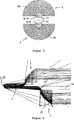
Eine erfindungsgemäße Leuchte für ein Fahrzeug weist im Wesentlichen einen Lichtleiter
Von der Leuchtdiode
Der Lichtleiter
Die Leuchtdiode
Gleiche Bauteile und Bauteilfunktionen unterschiedlicher Ausführungsbeispiele der Erfindung sind durch gleiche Bezugszeichen gekennzeichnet.Identical components and component functions of different embodiments of the invention are identified by the same reference numerals.
Die Reflektoren
An dem Lichtleiter
Die auf gegenüberliegenden Längsseiten des Lichtleitkörpers
BezugszeichenlisteLIST OF REFERENCE NUMBERS
- 11
- Lichtleiteroptical fiber
- 22
- erster Reflektorfirst reflector
- 33
- zweiter Reflektorsecond reflector
- 44
- Platinecircuit board
- 55
- Leuchtdiodeled
- 66
- Einkoppelflächecoupling surface
- 77
- erste Auskoppelflächefirst decoupling surface
- 88th
- zweite Auskoppelflächesecond decoupling surface
- 99
- erste Reflexionsflächefirst reflection surface
- 1010
- zweite Reflexionsflächesecond reflection surface
- 1111
- Hauptabstrahlrichtungmain radiation
- 1212
- Stirnseitefront
- 1313
- Einkoppeloptikcoupling optics
- 1414
- erste Totalreflexionsflächefirst total reflection surface
- 1515
- zweite Totalreflexionsflächesecond total reflection surface
- 1616
- optische Achseoptical axis
- 1717
- erste Auskoppeloptikfirst decoupling optics
- 1818
- zweite Auskoppeloptiksecond decoupling optics
- 1919
- Öffnungswinkelopening angle
ZITATE ENTHALTEN IN DER BESCHREIBUNG QUOTES INCLUDE IN THE DESCRIPTION
Diese Liste der vom Anmelder aufgeführten Dokumente wurde automatisiert erzeugt und ist ausschließlich zur besseren Information des Lesers aufgenommen. Die Liste ist nicht Bestandteil der deutschen Patent- bzw. Gebrauchsmusteranmeldung. Das DPMA übernimmt keinerlei Haftung für etwaige Fehler oder Auslassungen.This list of the documents listed by the applicant has been generated automatically and is included solely for the better information of the reader. The list is not part of the German patent or utility model application. The DPMA assumes no liability for any errors or omissions.
Zitierte PatentliteraturCited patent literature
- DE 19639829 C1[0002]DE 19639829 C1[0002]
- DE 102009022723 A1[0003]DE 102009022723 A1[0003]
- DE 102007019688 A1[0003]DE 102007019688 A1[0003]
Claims (10)
Translated fromGermanPriority Applications (1)
| Application Number | Priority Date | Filing Date | Title |
|---|---|---|---|
| DE102011001769ADE102011001769A1 (en) | 2011-04-04 | 2011-04-04 | Lamp e.g. headlamp for vehicle, has light conductor whose coupling surfaces couple light emitted from LED with respect to light from reflector, so that optical axis of LED is oriented parallel to main beam direction of light |
Applications Claiming Priority (1)
| Application Number | Priority Date | Filing Date | Title |
|---|---|---|---|
| DE102011001769ADE102011001769A1 (en) | 2011-04-04 | 2011-04-04 | Lamp e.g. headlamp for vehicle, has light conductor whose coupling surfaces couple light emitted from LED with respect to light from reflector, so that optical axis of LED is oriented parallel to main beam direction of light |
Publications (1)
| Publication Number | Publication Date |
|---|---|
| DE102011001769A1true DE102011001769A1 (en) | 2012-10-04 |
Family
ID=46844663
Family Applications (1)
| Application Number | Title | Priority Date | Filing Date |
|---|---|---|---|
| DE102011001769AWithdrawnDE102011001769A1 (en) | 2011-04-04 | 2011-04-04 | Lamp e.g. headlamp for vehicle, has light conductor whose coupling surfaces couple light emitted from LED with respect to light from reflector, so that optical axis of LED is oriented parallel to main beam direction of light |
Country Status (1)
| Country | Link |
|---|---|
| DE (1) | DE102011001769A1 (en) |
Cited By (12)
| Publication number | Priority date | Publication date | Assignee | Title |
|---|---|---|---|---|
| DE102012111666A1 (en)* | 2012-11-30 | 2014-06-05 | Osram Opto Semiconductors Gmbh | Illumination device for headlight of motor vehicle, has light conductive element conducting light of source of light toward light steering elements, which are arranged within housing and provided with reflector |
| WO2015010080A1 (en)* | 2013-07-18 | 2015-01-22 | Quarkstar Llc | Luminaire module with multiple light guide elements |
| US9028120B2 (en) | 2011-08-08 | 2015-05-12 | Quarkstar Llc | Illumination devices including multiple light emitting elements |
| US9081125B2 (en) | 2011-08-08 | 2015-07-14 | Quarkstar Llc | Illumination devices including multiple light emitting elements |
| EP2889529A3 (en)* | 2013-12-27 | 2015-08-19 | Automotive Lighting Reutlingen GmbH | Motor vehicle light with a linear or flat appearance |
| CN104930429A (en)* | 2014-03-20 | 2015-09-23 | 法雷奥照明公司 | Light Module For Daytime Running Lights Of A Motor Vehicle |
| US9206956B2 (en) | 2013-02-08 | 2015-12-08 | Quarkstar Llc | Illumination device providing direct and indirect illumination |
| US9354377B2 (en) | 2013-09-17 | 2016-05-31 | Quarkstar Llc | Light guide illumination device with light divergence modifier |
| US9410680B2 (en) | 2013-04-19 | 2016-08-09 | Quarkstar Llc | Illumination devices with adjustable optical elements |
| US9746173B2 (en) | 2012-09-13 | 2017-08-29 | Quarkstar Llc | Illumination devices including enclosure panels with luminaire modules |
| US9846272B2 (en) | 2012-09-13 | 2017-12-19 | Quarkstar Llc | Illumination systems providing direct and indirect illumination |
| CN107781781A (en)* | 2017-11-21 | 2018-03-09 | 上海小糸车灯有限公司 | Reflection-type beam condenser, car light and automobile |
Citations (6)
| Publication number | Priority date | Publication date | Assignee | Title |
|---|---|---|---|---|
| DE10065020A1 (en)* | 2000-09-04 | 2002-03-14 | Bosch Gmbh Robert | Motor vehicle head lamp with integral parking lamps, uses light guide under reflector directing light back onto the reflector for parking illumination |
| DE20218654U1 (en)* | 2002-12-02 | 2003-02-27 | Automotive Lighting Reutlingen GmbH, 72762 Reutlingen | Headlight has light from bulb transmitted directly and also indirectly as an expanded beam |
| US20040208019A1 (en)* | 2003-03-11 | 2004-10-21 | Koito Manufacturing Co., Ltd. | Vehicular lamp |
| DE10336162A1 (en)* | 2003-08-07 | 2005-02-24 | Schefenacker Vision Systems Germany Gmbh & Co. Kg | Lighting unit with light source and light guide |
| DE102007019688A1 (en) | 2007-04-24 | 2008-10-30 | Hella Kgaa Hueck & Co. | Signal light for motor vehicles, has housing, in which light source unit and multiple light conducting elements are assigned to light source unit and housing is covered by translucent sealing disk |
| DE102009022723A1 (en) | 2008-05-28 | 2009-12-03 | Osram Sylvania Inc., Danvers | Rear-mounted LED module for combination rear lights on motor vehicles |
- 2011
- 2011-04-04DEDE102011001769Apatent/DE102011001769A1/ennot_activeWithdrawn
Patent Citations (6)
| Publication number | Priority date | Publication date | Assignee | Title |
|---|---|---|---|---|
| DE10065020A1 (en)* | 2000-09-04 | 2002-03-14 | Bosch Gmbh Robert | Motor vehicle head lamp with integral parking lamps, uses light guide under reflector directing light back onto the reflector for parking illumination |
| DE20218654U1 (en)* | 2002-12-02 | 2003-02-27 | Automotive Lighting Reutlingen GmbH, 72762 Reutlingen | Headlight has light from bulb transmitted directly and also indirectly as an expanded beam |
| US20040208019A1 (en)* | 2003-03-11 | 2004-10-21 | Koito Manufacturing Co., Ltd. | Vehicular lamp |
| DE10336162A1 (en)* | 2003-08-07 | 2005-02-24 | Schefenacker Vision Systems Germany Gmbh & Co. Kg | Lighting unit with light source and light guide |
| DE102007019688A1 (en) | 2007-04-24 | 2008-10-30 | Hella Kgaa Hueck & Co. | Signal light for motor vehicles, has housing, in which light source unit and multiple light conducting elements are assigned to light source unit and housing is covered by translucent sealing disk |
| DE102009022723A1 (en) | 2008-05-28 | 2009-12-03 | Osram Sylvania Inc., Danvers | Rear-mounted LED module for combination rear lights on motor vehicles |
Cited By (35)
| Publication number | Priority date | Publication date | Assignee | Title |
|---|---|---|---|---|
| US10859758B2 (en) | 2011-08-08 | 2020-12-08 | Quarkstar Llc | Illumination devices including multiple light emitting elements |
| US9028120B2 (en) | 2011-08-08 | 2015-05-12 | Quarkstar Llc | Illumination devices including multiple light emitting elements |
| US9081125B2 (en) | 2011-08-08 | 2015-07-14 | Quarkstar Llc | Illumination devices including multiple light emitting elements |
| US10823905B2 (en) | 2011-08-08 | 2020-11-03 | Quarkstar Llc | Illumination devices including multiple light emitting elements |
| US11703631B2 (en) | 2011-08-08 | 2023-07-18 | Quarkstar Llc | Illumination devices including multiple light emitting elements |
| US9746173B2 (en) | 2012-09-13 | 2017-08-29 | Quarkstar Llc | Illumination devices including enclosure panels with luminaire modules |
| US10190762B2 (en) | 2012-09-13 | 2019-01-29 | Quarkstar Llc | Devices for workspace illumination having a panel forming an enclosure and a plurality of light emitters with primary and secondary optics |
| US9846272B2 (en) | 2012-09-13 | 2017-12-19 | Quarkstar Llc | Illumination systems providing direct and indirect illumination |
| DE102012111666A1 (en)* | 2012-11-30 | 2014-06-05 | Osram Opto Semiconductors Gmbh | Illumination device for headlight of motor vehicle, has light conductive element conducting light of source of light toward light steering elements, which are arranged within housing and provided with reflector |
| US9206956B2 (en) | 2013-02-08 | 2015-12-08 | Quarkstar Llc | Illumination device providing direct and indirect illumination |
| US9410680B2 (en) | 2013-04-19 | 2016-08-09 | Quarkstar Llc | Illumination devices with adjustable optical elements |
| US10180240B2 (en) | 2013-04-19 | 2019-01-15 | Quarkstar Llc | Illumination devices with adjustable optical elements |
| US9335462B2 (en) | 2013-07-18 | 2016-05-10 | Quarkstar Llc | Luminaire module with multiple light guide elements |
| US10132988B2 (en) | 2013-07-18 | 2018-11-20 | Quarkstar Llc | Luminaire module with multiple light guide elements |
| EP3273145A1 (en)* | 2013-07-18 | 2018-01-24 | Quarkstar LLC | Luminaire module with multiple light guide elements |
| WO2015010080A1 (en)* | 2013-07-18 | 2015-01-22 | Quarkstar Llc | Luminaire module with multiple light guide elements |
| US10838138B2 (en) | 2013-07-18 | 2020-11-17 | Quarkstar Llc | Luminaire module with multiple light guide elements |
| US10288798B2 (en) | 2013-07-18 | 2019-05-14 | Quarkstar Llc | Illumination device in which source light injection is non-parallel to device's optical axis |
| US9459398B2 (en) | 2013-07-18 | 2016-10-04 | Quarkstar Llc | Illumination device in which source light injection is non-parallel to device's optical axis |
| US10495807B2 (en) | 2013-09-17 | 2019-12-03 | Quarkstar Llc | Light guide illumination device for direct-indirect illumination |
| US10094969B2 (en) | 2013-09-17 | 2018-10-09 | Quarkstar Llc | Illumination device for direct-indirect illumination |
| US9354377B2 (en) | 2013-09-17 | 2016-05-31 | Quarkstar Llc | Light guide illumination device with light divergence modifier |
| US10203446B2 (en) | 2013-09-17 | 2019-02-12 | Quarkstar Llc | Light guide illumination device with light divergence modifier |
| US11150400B2 (en) | 2013-09-17 | 2021-10-19 | Quarkstar Llc | Illumination device for direct-indirect illumination |
| US9664839B2 (en) | 2013-09-17 | 2017-05-30 | Quarkstar Llc | Illumination device for direct-indirect illumination |
| US10705284B2 (en) | 2013-09-17 | 2020-07-07 | Quarkstar Llc | Luminaire with luminaire module |
| US10725229B2 (en) | 2013-09-17 | 2020-07-28 | Quarkstar Llc | Illumination device for direct-indirect illumination |
| US11693174B2 (en) | 2013-09-17 | 2023-07-04 | Quarkstar Llc | Illumination device for direct-indirect illumination |
| US9891371B2 (en) | 2013-09-17 | 2018-02-13 | Quarkstar Llc | Light guide illumination device for direct-indirect illumination |
| US10088121B2 (en) | 2013-12-27 | 2018-10-02 | Automotive Lighting Reutlingen Gmbh | Motor vehicle lamp having a linear or planar projection image |
| EP2889529A3 (en)* | 2013-12-27 | 2015-08-19 | Automotive Lighting Reutlingen GmbH | Motor vehicle light with a linear or flat appearance |
| CN104930429B (en)* | 2014-03-20 | 2019-06-18 | 法雷奥照明公司 | Lamp module for motor vehicles lamp daytime running |
| CN104930429A (en)* | 2014-03-20 | 2015-09-23 | 法雷奥照明公司 | Light Module For Daytime Running Lights Of A Motor Vehicle |
| CN107781781A (en)* | 2017-11-21 | 2018-03-09 | 上海小糸车灯有限公司 | Reflection-type beam condenser, car light and automobile |
| CN107781781B (en)* | 2017-11-21 | 2023-11-10 | 华域视觉科技(上海)有限公司 | Reflection type condenser, car lamp and car |
Similar Documents
| Publication | Publication Date | Title |
|---|---|---|
| DE102011001769A1 (en) | Lamp e.g. headlamp for vehicle, has light conductor whose coupling surfaces couple light emitted from LED with respect to light from reflector, so that optical axis of LED is oriented parallel to main beam direction of light | |
| DE102014211874B4 (en) | Lighting device of a motor vehicle | |
| DE102008038668B4 (en) | Signal light for vehicles, comprising a plurality of parallel light guide elements and a reflector | |
| DE102013104174A1 (en) | Lighting device for vehicles | |
| DE102004011961A1 (en) | vehicle light | |
| DE102011055429B4 (en) | Lighting device for vehicles | |
| DE102010061210A1 (en) | Lamp for vehicle, has light guide with light exit side towards which portion of light passed from primary light source via light input side of light guide is totally reflected and deflected | |
| DE102009010507A1 (en) | Lighting device for a motor vehicle | |
| EP3473918B1 (en) | Lighting device for a motor vehicle headlight | |
| DE102013104590A1 (en) | Lighting device for vehicles | |
| DE102006041942A1 (en) | Projection headlight for vehicle, has reflector devices extending in area between extension level of respective light source device and optical axis of lens, where light source devices are attached to respective reflector devices | |
| DE102008016764A1 (en) | Illumination device for motor vehicle, has reflection surfaces aligned and/or formed with respect to uncoupling elements, such that part of light reflected by reflection surfaces run through optical fiber | |
| EP1464888B1 (en) | Vehicular lamp | |
| DE102006008199B4 (en) | Luminaire unit for vehicles | |
| DE102014116983B4 (en) | LASER OPTICAL SYSTEM FOR A VEHICLE HEADLIGHT IN WHICH A BEAM LENS FOCUSING A LASER BEAM IS IN DIRECT CONTACT WITH A LUMINOUS BODY EXCITED BY THE LASER BEAM | |
| DE102009048032B4 (en) | Lighting device for vehicles with direction correction light guide elements for differently inclined circuit boards with light emitting diodes | |
| DE102011004349A1 (en) | Lighting device of a motor vehicle | |
| DE102015204747A1 (en) | Lighting device for a motor vehicle | |
| EP1557605B1 (en) | Headlamp for automotive vehicle | |
| DE102013110345A1 (en) | Lighting device for vehicles | |
| DE102012101451B4 (en) | Lighting device for vehicles | |
| DE102019118507A1 (en) | Lighting device for a motor vehicle | |
| EP2108883A2 (en) | Signal light for motor vehicles | |
| DE102008030746A1 (en) | Motor vehicle headlamp has an offset lamp, with a light guide to the light emission field, giving a coherent light beam without lamp heat | |
| DE102019211799B4 (en) | Device for generating a light distribution for a vehicle |
Legal Events
| Date | Code | Title | Description |
|---|---|---|---|
| R163 | Identified publications notified | ||
| R119 | Application deemed withdrawn, or ip right lapsed, due to non-payment of renewal fee |