DE102011000025A1 - Device for detecting goods - Google Patents
Device for detecting goodsDownload PDFInfo
- Publication number
- DE102011000025A1 DE102011000025A1DE102011000025ADE102011000025ADE102011000025A1DE 102011000025 A1DE102011000025 A1DE 102011000025A1DE 102011000025 ADE102011000025 ADE 102011000025ADE 102011000025 ADE102011000025 ADE 102011000025ADE 102011000025 A1DE102011000025 A1DE 102011000025A1
- Authority
- DE
- Germany
- Prior art keywords
- goods
- conveyor belts
- slot
- protective rail
- transport direction
- Prior art date
- Legal status (The legal status is an assumption and is not a legal conclusion. Google has not performed a legal analysis and makes no representation as to the accuracy of the status listed.)
- Ceased
Links
Images

Classifications
- G—PHYSICS
- G07—CHECKING-DEVICES
- G07G—REGISTERING THE RECEIPT OF CASH, VALUABLES, OR TOKENS
- G07G1/00—Cash registers
- G07G1/0036—Checkout procedures
- G07G1/0045—Checkout procedures with a code reader for reading of an identifying code of the article to be registered, e.g. barcode reader or radio-frequency identity [RFID] reader
Landscapes
- Physics & Mathematics (AREA)
- General Physics & Mathematics (AREA)
- Control Of Conveyors (AREA)
Abstract
Translated fromGermanDescription
Translated fromGermanDie Erfindung betrifft eine Vorrichtung zum Erfassen von Waren mit einer zwei hintereinander angeordnete Transportbänder aufweisenden Transporteinrichtung zum Transport der Waren in eine Transportrichtung, wobei zwischen den Transportbändern ein sich quer zu der Transportrichtung erstreckender Schlitz ausgebildet ist, und mit einer Abtasteinheit zum berührungslosen optischen Abtasten einer Auflagefläche der auf der Transporteinrichtung transportierten Waren durch den Schlitz.The invention relates to a device for detecting goods with a two successively arranged conveyor belts having transport means for transporting the goods in a transport direction, wherein between the conveyor belts is formed extending transversely to the transport direction slot, and with a scanning unit for non-contact optical scanning of a support surface the transported goods on the transport device through the slot.
Eine derartige Vorrichtung ist aus der
Die dem Schlitz zugeordnete Abtasteinheit ist den Transportbändern ebenso wie die weiteren Abtasteinheiten, die optional vorgesehen sein können, ortsfest zugeordnet. Die Abtasteinheit enthält typischerweise eine Quelle zum Emittieren optischer Strahlung sowie einen Detektor zum Empfangen der von den auf den Transportbändern transportierten Waren reflektierten Strahlung auf. Üblicherweise handelt es sich bei der Strahlung um Licht im sichtbaren bzw. ultraroten Wellenlängenbereich.The scanning unit associated with the slot is assigned to the conveyor belts as well as the other scanning units, which may optionally be provided in a stationary manner. The scanning unit typically includes a source for emitting optical radiation and a detector for receiving the radiation reflected from the goods being transported on the conveyor belts. Usually, the radiation is light in the visible or ultra-red wavelength range.
Obwohl sich die Vorrichtung grundsätzlich bewährt hat, können Waren bei der Übergabe von dem ersten Transportband an das zweite Transportband in den zwischen den Transportbändern ausgebildeten Schlitz hineinfallen mit der Folge, dass der Erfassungsvorgang unterbrochen werden muss. Überdies kann es in Ausnahmefällen zu einer Beschädigung der Waren bzw. ihrer Verpackung bei der Übergabe derselben von einem Transportband an das nächste kommen.Although the device has proven itself in principle, goods may fall into the slot formed between the conveyor belts during the transfer from the first conveyor belt to the second conveyor belt with the result that the detection process must be interrupted. Moreover, it may in exceptional cases to damage the goods or their packaging in the transfer of the same from one conveyor belt to the next.
Aufgabe der vorliegenden Erfindung ist es daher, die Vorrichtung derart weiterzubilden, dass die Zuverlässigkeit erhöht und einer Beschädigung der Waren vorgebeugt wird.Object of the present invention is therefore to develop the device such that the reliability is increased and damage to the goods is prevented.
Zur Lösung dieser Aufgabe ist die erfindungsgemäße Vorrichtung in Verbindung mit dem Oberbegriff des Patentanspruchs 1 dadurch gekennzeichnet, dass der Schlitz zumindest teilweise durch eine Schutzschiene überdeckt ist, welche sich quer zu der Transportrichtung erstreckt und beabstandet zu den Transportbändern angeordnet ist.To solve this problem, the device according to the invention in conjunction with the preamble of
Der besondere Vorteil der Erfindung besteht darin, dass Waren aufgrund des Vorsehen der den zwischen den Transportbändern ausgebildeten Schlitz teilweise abdeckenden Schutzschiene besonders zuverlässig von dem einen Transportband an das andere Transportband übergeben werden. Die Schutzschiene verhindert hierbei, dass die Waren in den Schlitz hineinfallen und dient zugleich als Träger bzw. Stütze für die Waren in vertikaler Richtung. Vorzugsweise überdeckt die Schutzschiene einen großen Teil des Schlitzes, so dass lediglich ein für die optische Abtastung der Waren funktionsnotwendiger, schmaler Spalt und/oder zu beiden Seiten der Schutzschiene je ein Funktionsspalt zwischen der Schutzschiene und den bewegten Transportbändern ausgebildet ist. Der Funktionsspalt gewährleistet hierbei, dass es nicht zu einer Berührung zwischen den Transportbändern und der Schutzschiene und infolgedessen nicht zu einer Beschädigung der Transportbänder bzw. der Schutzschiene kommt.The particular advantage of the invention is that goods are handed over due to the provision of the trained between the conveyor belts partially covering guard rail particularly reliable from the one conveyor belt to the other conveyor belt. The protective rail prevents this case that the goods fall into the slot and also serves as a support or support for the goods in the vertical direction. Preferably, the protective rail covers a large part of the slot, so that only one functionally necessary for the optical scanning of the goods, narrow gap and / or on both sides of the guard rail is formed a function gap between the guard rail and the moving conveyor belts. In this case, the functional gap ensures that there is no contact between the conveyor belts and the protective rail and, as a result, no damage to the conveyor belts or the protective rail.
Die Transportbänder sind beispielsweise als Endlosförderbänder ausgestaltet, wobei die Waren auf dem Obertrum der Endlosförderbänder in Transportrichtung transportiert werden.The conveyor belts are configured for example as endless conveyor belts, wherein the goods are transported on the upper run of the endless conveyor belts in the transport direction.
Nach einer bevorzugten Ausführungsform der Erfindung weist die Schutzschiene eine langgestreckte, quer zu der Transportrichtung orientierte Ausnehmung auf. Durch die Ausnehmung hindurch wird die Auflageseite der Waren mittels der Abtasteinheit abgetastet. Vorteilhaft kann durch das Vorsehen der langgestreckten Ausnehmung der Spalt zwischen den beiden Transportbänder durch eine einzige Schutzschiene überdeckt werden. Die Ausnehmung, die hierbei den Abtastspalt definiert, kann beispielsweise mittig sowohl in der Schutzschiene als auch mittig zwischen den zwei Transportbändern vorgesehen werden. Hierdurch ist sichergestellt, dass bei mittiger Anordnung der Abtasteinheit in dem Schlitz die Auflageseite unter einem günstigen Abtastwinkel abgetastet werden kann. Vorzugsweise erfolgt die Abtastung unter einem 90°-Winkel zu der Auflageseite der Waren.According to a preferred embodiment of the invention, the protective rail on an elongated, oriented transversely to the transport direction recess. Through the recess, the support side of the goods is scanned by means of the scanning unit. Advantageously, by providing the elongated recess, the gap between the two conveyor belts can be covered by a single protective rail. The recess, which in this case defines the scanning gap, can for example be provided centrally both in the protective rail and in the middle between the two conveyor belts. This ensures that in the central slot of the scanning unit in the slot, the support side can be scanned at a favorable scanning angle. Preferably the scanning is done at a 90 ° angle to the support side of the goods.
Nach einer Weiterbildung der Erfindung ist die Schutzschiene beweglich, insbesondere um eine Längsrichtung der Schutzschiene schwenkbar in Bezug auf die Transportbänder gehalten. Insbesondere kann vorgesehen sein, dass die Schutzschiene beim Eintreten von Waren in den Schlitz angehoben, das heißt von den Transportbändern entfernt wird. Die in den Schlitz eintretenden Waren selbst können hierbei die Schutzschiene anheben. Vorteilhaft wird durch die bewegliche Anordnung der Schutzschiene einer Beschädigung der Waren bzw. ihrer Verpackung selbst dann vorgebeugt, wenn die Ware bei der Übergabe von dem ersten Transportband an das zweite Transportband in den Abtastspalt bzw. einen der beiden Funktionsspalten hineingelangt. Dies kann beispielsweise der Fall sein, wenn sehr flache Gegenstände, beispielsweise Zeitungen oder einzelne Blätter von Zeitschriften, auf dem Transportband gefördert werden.According to a development of the invention, the protective rail is movable, in particular held about a longitudinal direction of the guard rail pivotally with respect to the conveyor belts. In particular, it can be provided that the protective rail is raised when entering goods in the slot, that is removed from the conveyor belts. The entering into the slot goods themselves can hereby raise the guard rail. Advantageously, by the movable arrangement of the guard rail damage to the goods or their packaging is prevented even if the goods get in the transfer of the first conveyor belt to the second conveyor belt in the Abtastspalt or one of the two function columns. This may for example be the case when very flat objects, such as newspapers or individual sheets of magazines, are conveyed on the conveyor belt.
Nach einer Weiterbildung der Erfindung ist der Schutzschiene zumindest ein Sensor zugeordnet zur Erfassung von Waren, die in den zwischen den Transportbändern gebildeten Schlitz eintreten. Vorteilhaft kann durch das Vorsehen einer geeigneten Sensorik das Eintreten von Waren in den Schlitz automatisiert erkannt werden. Dies ist beispielsweise an Selbstbedienungskassensystemen, welche nicht von geschultem Personal bedient werden und die von dem Kunden auf das Transportband gelegten Waren im Wesentlichen selbsttätig erfassen, von großem Vorteil. Beispielsweise kann als Sensor ein optischer Sensor (Lichtschranke oder dergleichen) vorgesehen sein. Ebenso ist möglich, der Schutzschiene einen Kraftsensor zuzuordnen, welcher einen Kraftanstieg detektiert, der Folge des Eintretens von Waren in den Abtastspalt bzw. eine Funktionsspalte ist. Ebenso kann der beweglich gelagerten Schutzschiene ein Bewegungssensor zugeordnet werden.According to a development of the invention, the protective rail is assigned at least one sensor for detecting goods that enter the slot formed between the conveyor belts. Advantageously, by the introduction of suitable sensors, the entry of goods into the slot can be detected automatically. This is of great advantage, for example, in self-service checkout systems which are not operated by trained personnel and which essentially detect automatically the goods put on the conveyor belt by the customer. For example, can be provided as a sensor, an optical sensor (light barrier or the like). It is also possible to assign the guard rail to a force sensor which detects an increase in force, the result of the entry of goods into the scanning gap or a function column. Likewise, the movable guard rail can be assigned a motion sensor.
Nach einer Weiterbildung der Erfindung ist eine mit mindestens einem Sensor und mit einer die Transportbänder antreibenden Antriebseinheit zusammenwirkende Steuereinheit vorgesehen. Vorteilhaft können durch das Vorsehen der Steuereinheit die Transportbänder beim Eintritt von Waren in den Schlitz gestoppt werden. Durch den Stopp der Transportbänder kann zum einen einer weiteren Beschädigung von Waren bzw. deren Verpackung, welche zumindest teilweise in den Schlitz hineinragen, vorgebeugt werden. Zum anderen wird die Möglichkeit geschaffen, während des Stillstands der Transportbänder die in den Schlitz gelangten Waren aus demselben zu entnehmen.According to a development of the invention, a control unit cooperating with at least one sensor and with a drive unit driving the conveyor belts is provided. Advantageously, by providing the control unit, the conveyor belts can be stopped when goods enter the slot. By stopping the conveyor belts can on the one hand further damage of goods or their packaging, which protrude at least partially into the slot, be prevented. On the other hand, the possibility is created during the stoppage of the conveyor belts to remove the goods in the slot goods from the same.
Nach einer Weiterbildung der Erfindung sind die Transportbänder höhenversetzt zueinander angeordnet, wobei das in Transportrichtung gesehen vordere Transportband unterhalb des in Transportrichtung gesehen hinteren Transportbands angeordnet ist. Eine Oberfläche der Schutzschiene ist zur Verbindung der Auflageflächen der Transportbänder im Bereich des Schlitzes geneigt angeordnet. Vorteilhaft wird durch die geneigte Anordnung der Schutzschiene und den Höhenversatz der Transportbänder die Übergabe der Waren von dem ersten Transportband an das zweite Transportband vereinfacht. Die Schutzschiene wirkt hierbei nach Art einer Warenrutsche. Zudem kann eine Transportgeschwindigkeit der Transportbänder so gewählt werden, dass die Waren insbesondere über den zwischen dem ersten Transportband und der Schutzschiene gebildeten Funktionsspalt hinweg „schießen”. Hierdurch sinkt das Risiko, dass Waren in diesen Funktionsspalt gelangen.According to a development of the invention, the conveyor belts are arranged offset in height to one another, wherein the front transport belt seen in the transport direction is arranged below the rear transport belt seen in the transport direction. A surface of the protective rail is arranged inclined to connect the bearing surfaces of the conveyor belts in the region of the slot. Advantageously, the transfer of the goods from the first conveyor belt to the second conveyor belt is simplified by the inclined arrangement of the protective rail and the vertical offset of the conveyor belts. The protective rail acts in the manner of a slide. In addition, a transport speed of the conveyor belts can be selected so that the goods "shoot" in particular over the functional gap formed between the first conveyor belt and the protective rail. This reduces the risk of goods getting into this functional gap.
Nach einer Weiterbildung der Erfindung sind die Transportbänder, die Schutzschiene und die der Schutzschiene bzw. dem durch die Schutzschiene abgedeckten Schlitz zugeordnete Abtasteinheit an einem gemeinsamen Trägerbauteil befestigt. Vorteilhaft wird durch das Vorsehen eines gemeinsamen Trägerbauteils eine genaue Lagezuordnung der einzelnen Funktionskomponenten (Transportbänder, Schutzschiene, Abtasteinheit) zueinander gewährleistet mit der Folge, dass die Waren besonders zuverlässig und sicher optisch abgetastet und erkannt werden können. Hierbei können an dem Trägerbauteil oder den Funktionskomponenten Justagemittel vorgesehen sein, um die Positionierung der Funktionskomponenten zueinander bei der Montage und Inbetriebnahme des Systems einmalig exakt einzustellen und zu fixieren. Als Justagemittel können beispielsweise Langlöcher in dem Trägerbauteil vorgesehen sein. Optional können an dem Trägerbauteil weitere Funktionskomponenten der Vorrichtung, beispielsweise die weiteren Abtasteinheiten, mittels derer die weiteren Außenseiten der Waren optisch abgetastet werden, befestigt werden. In diesem Fall sind auch diese in ihrer Lage und relativen Position zu der dem Schlitz zugeordneten Abtasteinheit, zu den Transportbändern und zu der Schutzschiene positioniert.According to a development of the invention, the conveyor belts, the protective rail and the protective rail or the slot covered by the protective rail associated scanning unit are attached to a common carrier component. Advantageously, the provision of a common carrier component ensures a precise positional assignment of the individual functional components (conveyor belts, protective rail, scanning unit) to one another, with the result that the goods can be optically scanned and detected in a particularly reliable and secure manner. In this case, adjusting means can be provided on the carrier component or the functional components in order to precisely set and fix the positioning of the functional components relative to one another during assembly and commissioning of the system. As adjustment means, for example, slots can be provided in the support member. Optionally, further functional components of the device, for example the further scanning units, by means of which the further outer sides of the goods are optically scanned, can be fastened to the carrier component. In this case too, these are positioned in their position and relative position to the scanning unit associated with the slot, to the conveyor belts and to the protective rail.
Weitere Vorteile der Erfindung ergeben sich aus den weiteren Unteransprüchen.Further advantages of the invention will become apparent from the further subclaims.
Ein Ausführungsbeispiel der Erfindung wird nachfolgend anhand der Figuren näher erläutert.An embodiment of the invention will be explained in more detail with reference to FIGS.
Es zeigen:Show it:
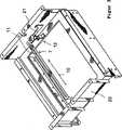
Eine erfindungsgemäße Vorrichtung gemäß
Der Schlitz
Die Schutzschiene
Wie sich aus der detailvergrößerten Darstellung nach
Da die Auflagefläche
Der Schlitz
Zum Abtasten der Auflageseite der Ware wird die Ware auf dem ersten Transportband
Ausnahmsweise kann eine Ware beim Verlassen des ersten Transportbands
Das Anheben der Schutzschiene
Der zweite Funktionsspalt
Selbstverständlich können den Transportbänder
Grundsätzlich muss der Sensor nicht in die Verbindungseinheit
Statt die Schutzschienen
Das Trägerbauteil
Nach einem alternativen, nicht dargestellten Ausführungsbeispiel der Erfindung kann die Schutzschiene
Gleiche Bauteile und Bauteilfunktionen sind mit den gleichen Bezugszeichen versehen.The same components and component functions are provided with the same reference numerals.
BezugszeichenlisteLIST OF REFERENCE NUMBERS
- 11
- Transporteinrichtungtransport means
- 22
- Transportrichtungtransport direction
- 33
- Abtasteinheitscanning
- 44
- erstes Transportbandfirst conveyor belt
- 55
- zweites Transportbandsecond conveyor belt
- 66
- Schlitzslot
- 77
- Schutzschieneguard rail
- 88th
- erster Funktionsspaltfirst functional gap
- 99
- zweiter Funktionsspaltsecond functional gap
- 1010
- Längsrichtunglongitudinal direction
- 1111
- Ausnehmungrecess
- 1212
- Verbindungseinheitconnecting unit
- 1313
- Schwenkrichtungpan direction
- 1414
- Steuereinheitcontrol unit
- 1515
- Antriebseinheitdrive unit
- 1616
- Auflageflächebearing surface
- 1717
- Auflageflächebearing surface
- 1818
- Oberflächesurface
- 19 19
- Stirnseitefront
- 2020
- Trägerbauteilsupport component
- 2121
- Schwenkarmswivel arm
- αα
- Winkelangle
ZITATE ENTHALTEN IN DER BESCHREIBUNG QUOTES INCLUDE IN THE DESCRIPTION
Diese Liste der vom Anmelder aufgeführten Dokumente wurde automatisiert erzeugt und ist ausschließlich zur besseren Information des Lesers aufgenommen. Die Liste ist nicht Bestandteil der deutschen Patent- bzw. Gebrauchsmusteranmeldung. Das DPMA übernimmt keinerlei Haftung für etwaige Fehler oder Auslassungen.This list of the documents listed by the applicant has been generated automatically and is included solely for the better information of the reader. The list is not part of the German patent or utility model application. The DPMA assumes no liability for any errors or omissions.
Zitierte PatentliteraturCited patent literature
- DE 10141429 C1[0002]DE 10141429 C1[0002]
Claims (10)
Translated fromGermanPriority Applications (4)
| Application Number | Priority Date | Filing Date | Title |
|---|---|---|---|
| DE102011000025ADE102011000025A1 (en) | 2011-01-04 | 2011-01-04 | Device for detecting goods |
| ES11009450.5TES2471066T3 (en) | 2011-01-04 | 2011-11-30 | Merchandise Detection Device |
| EP11009450.5AEP2472485B1 (en) | 2011-01-04 | 2011-11-30 | Device for collecting goods |
| US13/401,243US8627946B2 (en) | 2011-01-04 | 2012-02-21 | Device for detecting items |
Applications Claiming Priority (1)
| Application Number | Priority Date | Filing Date | Title |
|---|---|---|---|
| DE102011000025ADE102011000025A1 (en) | 2011-01-04 | 2011-01-04 | Device for detecting goods |
Publications (1)
| Publication Number | Publication Date |
|---|---|
| DE102011000025A1true DE102011000025A1 (en) | 2012-07-05 |
Family
ID=45318758
Family Applications (1)
| Application Number | Title | Priority Date | Filing Date |
|---|---|---|---|
| DE102011000025ACeasedDE102011000025A1 (en) | 2011-01-04 | 2011-01-04 | Device for detecting goods |
Country Status (4)
| Country | Link |
|---|---|
| US (1) | US8627946B2 (en) |
| EP (1) | EP2472485B1 (en) |
| DE (1) | DE102011000025A1 (en) |
| ES (1) | ES2471066T3 (en) |
Families Citing this family (11)
| Publication number | Priority date | Publication date | Assignee | Title |
|---|---|---|---|---|
| DE102009013635A1 (en)* | 2009-03-18 | 2010-09-23 | Wincor Nixdorf International Gmbh | Device for detecting goods |
| US9595029B1 (en) | 2012-10-04 | 2017-03-14 | Ecr Software Corporation | System and method for self-checkout, scan portal, and pay station environments |
| US10089614B1 (en) | 2013-10-04 | 2018-10-02 | Ecr Software Corporation | System and method for self-checkout, scan portal, and pay station environments |
| WO2015111418A1 (en)* | 2014-01-27 | 2015-07-30 | 株式会社ブリヂストン | Sensor, and monitoring system |
| US9230146B1 (en)* | 2014-11-17 | 2016-01-05 | Datalogic IP Tech Srl | System, device and method employing machine-readable symbol reader and shield |
| CN105270813A (en)* | 2015-09-25 | 2016-01-27 | 无锡日联科技股份有限公司 | Security check Internet-of-things system |
| US10212304B2 (en)* | 2017-01-17 | 2019-02-19 | Xerox Corporation | Document scanner |
| US20190002210A1 (en)* | 2017-06-30 | 2019-01-03 | Dematic Corp. | Conveyor spacer guard |
| US20220309714A1 (en)* | 2019-08-22 | 2022-09-29 | Nec Corporation | Registration system, processing device, and processing method |
| US10625952B1 (en)* | 2019-10-18 | 2020-04-21 | Grey Orange Pte. Ltd. | Induction station for conveying packages in storage facility |
| CN111348398A (en)* | 2020-02-28 | 2020-06-30 | 长园装备制造有限公司 | Conveyor and conveying method |
Citations (2)
| Publication number | Priority date | Publication date | Assignee | Title |
|---|---|---|---|---|
| DE2264518A1 (en)* | 1971-04-30 | 1974-01-10 | Rca Corp | DEVICE FOR THE IDENTIFICATION OF OBJECTS |
| DE10141429C1 (en) | 2001-08-23 | 2003-01-23 | Wincor Nixdorf Int Gmbh | Arrangement for optically scanning machine readable marking has scanner in scratch- and chemical-resistant transparent cylinder driven in synchronism with object transport device |
Family Cites Families (30)
| Publication number | Priority date | Publication date | Assignee | Title |
|---|---|---|---|---|
| US3485339A (en)* | 1967-12-11 | 1969-12-23 | Fairbank Morse Inc | Article spacing system |
| CH529390A (en)* | 1970-07-03 | 1972-10-15 | Zellweger Uster Ag | Method for recording, machine reading and recognition of information in the form of code characters, device for carrying out the method and application of the method |
| US3708655A (en) | 1971-04-30 | 1973-01-02 | Rca Corp | Article identification apparatus |
| GB1445098A (en)* | 1973-04-04 | 1976-08-04 | Plessey Co Ltd | Optical code recognition |
| US5543607A (en) | 1991-02-16 | 1996-08-06 | Hitachi, Ltd. | Self check-out system and POS system |
| US5252814A (en)* | 1992-08-17 | 1993-10-12 | Ncr Corporation | Multi-scanner checkout counter using digitizer panel to determine X-Y location of scanned items |
| US5446271A (en) | 1993-08-06 | 1995-08-29 | Spectra-Physics Scanning Systems, Inc. | Omnidirectional scanning method and apparatus |
| US5484049A (en)* | 1994-02-22 | 1996-01-16 | United Parcel Service Of America, Inc. | Package measuring system and accumulator |
| US6431450B1 (en)* | 1999-09-13 | 2002-08-13 | Advanced Technology & Research Corp. | Barcode scanning system for reading labels at the bottom of packages on a conveyor |
| US6812426B1 (en)* | 2000-07-24 | 2004-11-02 | Rapiscan Security Products | Automatic reject unit spacer and diverter |
| FI111754B (en)* | 2000-08-25 | 2003-09-15 | Outokumpu Oy | Ways of measuring the surface level of a material layer lying on a conveyor track and to be heat treated |
| DE20206878U1 (en) | 2002-04-30 | 2002-08-08 | Merlaku, Kastriot, 80807 München | Shopping goods treadmill for supermarket checkouts |
| DE10235865A1 (en) | 2002-08-05 | 2004-02-26 | Senol Gideroglu | Conveyor for supermarket check-out comprises moving belt divided into zones by visible markers which are activated by activation system at beginning of zone and deactivated by second system at its end |
| DE10323691A1 (en) | 2003-05-22 | 2004-12-23 | Wincor Nixdorf International Gmbh | Self-service checkout |
| EP1536386B1 (en) | 2003-11-14 | 2006-06-21 | Wincor Nixdorf International GmbH | Reverse vending apparatus |
| US7100824B2 (en) | 2004-02-27 | 2006-09-05 | Evolution Robotics, Inc. | System and methods for merchandise checkout |
| DE202004021433U1 (en) | 2004-04-02 | 2008-02-07 | Wincor Nixdorf International Gmbh | Self-service product detection station |
| DE202005007089U1 (en) | 2005-03-04 | 2005-07-14 | Mahlo Gmbh & Co. Kg | Sensor arrangement for optically detecting the edges of a product, e.g. to measure its width, comprises point light sources and a optical fiber arrangement that detects light reflected back from the product under-surface |
| USD536192S1 (en) | 2005-06-09 | 2007-02-06 | Wincor Nixdorf International Gmbh | Scan and pay tower |
| US20070023257A1 (en)* | 2005-07-28 | 2007-02-01 | Schiesser Ricardo N | Breakaway conveyor discharge |
| US8074785B2 (en) | 2006-11-15 | 2011-12-13 | Wincor Nixdorf International Gmbh | Device and method for optically scanning a machine-readable label applied to an object |
| DE102007022556A1 (en) | 2007-05-14 | 2008-11-20 | Wincor Nixdorf International Gmbh | Optimized document management in self-service systems |
| US8876001B2 (en) | 2007-08-07 | 2014-11-04 | Ncr Corporation | Methods and apparatus for image recognition in checkout verification |
| DE202007017525U1 (en) | 2007-12-15 | 2008-03-13 | Wincor Nixdorf International Gmbh | POS system |
| US7648020B2 (en)* | 2008-03-03 | 2010-01-19 | International Business Machines Corporation | Transition plate position sensor for safe check-out counter conveyor operation |
| US8201681B2 (en)* | 2008-07-14 | 2012-06-19 | Siemens Industry, Inc. | Method for gapping for sortation rate maximization |
| DE102008044795A1 (en) | 2008-08-28 | 2010-03-04 | Wincor Nixdorf International Gmbh | Goods acquisition at self-service checkout systems |
| DE202008012862U1 (en) | 2008-09-24 | 2011-02-03 | Ilić, Ljubisa | Arrangement for separating goods on a cash register treadmill |
| DE102009013635A1 (en) | 2009-03-18 | 2010-09-23 | Wincor Nixdorf International Gmbh | Device for detecting goods |
| DE102009037124A1 (en)* | 2009-08-11 | 2011-02-17 | Wincor Nixdorf International Gmbh | Apparatus and method for optically scanning a machine-readable mark |
- 2011
- 2011-01-04DEDE102011000025Apatent/DE102011000025A1/ennot_activeCeased
- 2011-11-30EPEP11009450.5Apatent/EP2472485B1/enactiveActive
- 2011-11-30ESES11009450.5Tpatent/ES2471066T3/enactiveActive
- 2012
- 2012-02-21USUS13/401,243patent/US8627946B2/enactiveActive
Patent Citations (2)
| Publication number | Priority date | Publication date | Assignee | Title |
|---|---|---|---|---|
| DE2264518A1 (en)* | 1971-04-30 | 1974-01-10 | Rca Corp | DEVICE FOR THE IDENTIFICATION OF OBJECTS |
| DE10141429C1 (en) | 2001-08-23 | 2003-01-23 | Wincor Nixdorf Int Gmbh | Arrangement for optically scanning machine readable marking has scanner in scratch- and chemical-resistant transparent cylinder driven in synchronism with object transport device |
Also Published As
| Publication number | Publication date |
|---|---|
| EP2472485A1 (en) | 2012-07-04 |
| EP2472485B1 (en) | 2014-03-26 |
| ES2471066T3 (en) | 2014-06-25 |
| US20120247924A1 (en) | 2012-10-04 |
| US8627946B2 (en) | 2014-01-14 |
Similar Documents
| Publication | Publication Date | Title |
|---|---|---|
| EP2472485B1 (en) | Device for collecting goods | |
| DE60205980T2 (en) | Loading bridge for loading air freight | |
| DE102013003768B4 (en) | Method and device for picking up horizontally stored commission goods | |
| EP2886494B1 (en) | Conveyor device for conveying suspended objects | |
| EP3225571B1 (en) | Conveying device for conveying hanging items | |
| DE69814684T2 (en) | JOINT SPONSORS | |
| DE3701931C2 (en) | ||
| EP2987910A1 (en) | Self-propelled milling machine, and method for unloading milled goods | |
| DE10027485A1 (en) | Device for monitoring a conveyor belt for a bulk material such as stone or ore consists on an opto-electronic camera mounted above an area where damage could occur due to oversize or foreign material | |
| DE2416123A1 (en) | EXIT CONTROL STATION | |
| EP0603468B1 (en) | Overhead conveyor system having a push-out device with overload function | |
| EP3208215B1 (en) | Transport device to transport workload carrying devices from or to one or more machine tools | |
| EP2003076A2 (en) | Piece good transport device with scanner | |
| EP2802441B1 (en) | Wood-working machine and method for the operation thereof | |
| EP2472432B1 (en) | Device for collecting goods, assembly and operating method | |
| EP2474956B1 (en) | Transport unit and method for operating the same | |
| EP3221239B1 (en) | Radio-frequency identification arrangement for a chain conveyor for piece goods and chain conveyor having such a radio-frequency identification arrangement | |
| EP3452948B1 (en) | Scanner unit | |
| EP0770849A2 (en) | Device to determine the form of plate-like objects | |
| EP3822198B1 (en) | Piece good detection assembly | |
| DE4240664A1 (en) | Conveyor system, e.g. for goods on palettes - has carrier devices on parallel rails, and elongated housing carrying electrical, pneumatic and=or hydraulic lines | |
| CH719738A1 (en) | Conveyor system with a product delivery control. | |
| EP3322654B1 (en) | Conveyor device for transporting individual products | |
| EP3715286A1 (en) | Adjustable anti-jamming protection for belt conveyor | |
| DE102020108460A1 (en) | Conveyor system and method for operating such a conveyor system |
Legal Events
| Date | Code | Title | Description |
|---|---|---|---|
| R163 | Identified publications notified | ||
| R083 | Amendment of/additions to inventor(s) | ||
| R012 | Request for examination validly filed | ||
| R081 | Change of applicant/patentee | Owner name:DIEBOLD NIXDORF SYSTEMS GMBH, DE Free format text:FORMER OWNER: WINCOR NIXDORF INTERNATIONAL GMBH, 33106 PADERBORN, DE | |
| R002 | Refusal decision in examination/registration proceedings | ||
| R003 | Refusal decision now final |