DE102010063069A1 - Hand tool, in particular drill or Schraubbohrmaschine - Google Patents
Hand tool, in particular drill or SchraubbohrmaschineDownload PDFInfo
- Publication number
- DE102010063069A1 DE102010063069A1DE102010063069ADE102010063069ADE102010063069A1DE 102010063069 A1DE102010063069 A1DE 102010063069A1DE 102010063069 ADE102010063069 ADE 102010063069ADE 102010063069 ADE102010063069 ADE 102010063069ADE 102010063069 A1DE102010063069 A1DE 102010063069A1
- Authority
- DE
- Germany
- Prior art keywords
- drive motor
- hand tool
- housing
- area
- drive
- Prior art date
- Legal status (The legal status is an assumption and is not a legal conclusion. Google has not performed a legal analysis and makes no representation as to the accuracy of the status listed.)
- Withdrawn
Links
- 230000005540biological transmissionEffects0.000claimsdescription23
- 230000008878couplingEffects0.000description3
- 238000010168coupling processMethods0.000description3
- 238000005859coupling reactionMethods0.000description3
- 238000005452bendingMethods0.000description1
- 210000001520combAnatomy0.000description1
- 230000001419dependent effectEffects0.000description1
- 238000011161developmentMethods0.000description1
- 230000018109developmental processEffects0.000description1
- 230000005611electricityEffects0.000description1
- 230000005484gravityEffects0.000description1
- 238000002347injectionMethods0.000description1
- 239000007924injectionSubstances0.000description1
- 230000001105regulatory effectEffects0.000description1
Images
Classifications
- B—PERFORMING OPERATIONS; TRANSPORTING
- B25—HAND TOOLS; PORTABLE POWER-DRIVEN TOOLS; MANIPULATORS
- B25B—TOOLS OR BENCH DEVICES NOT OTHERWISE PROVIDED FOR, FOR FASTENING, CONNECTING, DISENGAGING OR HOLDING
- B25B21/00—Portable power-driven screw or nut setting or loosening tools; Attachments for drilling apparatus serving the same purpose
- B—PERFORMING OPERATIONS; TRANSPORTING
- B23—MACHINE TOOLS; METAL-WORKING NOT OTHERWISE PROVIDED FOR
- B23B—TURNING; BORING
- B23B45/00—Hand-held or like portable drilling machines, e.g. drill guns; Equipment therefor
- B23B45/001—Housing of the drill, e.g. handgrip
- B—PERFORMING OPERATIONS; TRANSPORTING
- B23—MACHINE TOOLS; METAL-WORKING NOT OTHERWISE PROVIDED FOR
- B23B—TURNING; BORING
- B23B45/00—Hand-held or like portable drilling machines, e.g. drill guns; Equipment therefor
- B23B45/02—Hand-held or like portable drilling machines, e.g. drill guns; Equipment therefor driven by electric power
- B—PERFORMING OPERATIONS; TRANSPORTING
- B25—HAND TOOLS; PORTABLE POWER-DRIVEN TOOLS; MANIPULATORS
- B25F—COMBINATION OR MULTI-PURPOSE TOOLS NOT OTHERWISE PROVIDED FOR; DETAILS OR COMPONENTS OF PORTABLE POWER-DRIVEN TOOLS NOT PARTICULARLY RELATED TO THE OPERATIONS PERFORMED AND NOT OTHERWISE PROVIDED FOR
- B25F5/00—Details or components of portable power-driven tools not particularly related to the operations performed and not otherwise provided for
- B25F5/02—Construction of casings, bodies or handles
Landscapes
- Engineering & Computer Science (AREA)
- Mechanical Engineering (AREA)
- Drilling And Boring (AREA)
Abstract
Translated fromGermanDescription
Translated fromGermanStand der TechnikState of the art
Die Erfindung betrifft eine Handwerkzeugmaschine, insbesondere eine Bohrmaschine oder eine Schraubbohrmaschine nach dem Oberbegriff des Anspruchs 1.The invention relates to a hand tool, in particular a drill or a Schraubbohrmaschine according to the preamble of claim 1.
Eine derartige Handwerkzeugmaschine ist bereits aus der Praxis bekannt, wobei in dem Gehäuse der Handwerkzeugmaschine in einem ersten Gehäusebereich in Verlängerung einer Werkzeugaufnahme ein Getriebe angeordnet ist, das über eine Antriebswelle von einem Antriebsmotor angetrieben ist. Hierbei befindet sich der Antriebsmotor zusammen mit einer Schalteinheit in einem zweiten Gehäusebereich der Handwerkzeugmaschine, der gleichzeitig als Handgriff dient und im Wesentlichen senkrecht zum ersten Gehäusebereich angeordnet ist. Wesentlich dabei ist, dass sich die Schalteinheit zwischen dem Getriebe und dem Antriebsmotor befindet, so dass zur Überbrückung der Distanz zwischen dem Antriebsmotor und dem Getriebe eine relativ lang ausgebildete Antriebswelle erforderlich ist. Dies hat zur Folge, dass der zweite Gehäusebereich infolge der Antriebswelle einen relativ großen Querschnitt aufweist und die Kraftübertragung mittels der Antriebswelle aufgrund der zur Abstützung der Antriebswelle erforderlichen Lager relativ aufwendig und somit kostenintensiv ausgebildet ist. Als weiterer Nachteil ist anzuführen, dass zur Überbrückung der Distanz zwischen einem am unteren Ende des zweiten Gehäusebereichs angeordneten Batteriepack und der Schalteinheit relativ lang ausgebildete Verbindungskabel erforderlich sind, die die elektrische Kontaktierung der Handwerkzeugmaschine bzw. dessen Antrieb zusätzlich erschweren bzw. den Aufwand erhöhen.Such a hand tool machine is already known from practice, wherein in the housing of the power tool in a first housing portion in extension of a tool holder, a transmission is arranged, which is driven via a drive shaft of a drive motor. Here, the drive motor is together with a switching unit in a second housing portion of the power tool, which also serves as a handle and is arranged substantially perpendicular to the first housing portion. It is essential that the switching unit is located between the transmission and the drive motor, so that a relatively long trained drive shaft is required to bridge the distance between the drive motor and the transmission. This has the consequence that the second housing portion has a relatively large cross-section due to the drive shaft and the power transmission by means of the drive shaft is relatively complicated and thus costly due to the required for supporting the drive shaft bearing. Another disadvantage is to be mentioned that for bridging the distance between a arranged at the lower end of the second housing portion battery pack and the switching unit relatively long trained connection cables are required, which further complicate the electrical contact of the power tool or its drive or increase the effort.
Offenbarung der ErfindungDisclosure of the invention
Ausgehend von dem dargestellten Stand der Technik liegt der Erfindung die Aufgabe zugrunde, eine Handwerkzeugmaschine, insbesondere eine Bohrmaschine oder eine Schraubbohrmaschine nach dem Oberbegriff des Anspruchs 1 derart weiterzubilden, dass ein möglichst kompakter Aufbau der Handwerkzeugmaschine ermöglicht wird. Zusätzlich soll der konstruktive Aufwand hinsichtlich der Ankoppelung des Antriebsmotors an das Getriebe möglichst einfach gestaltet werden und eine kostengünstige Herstellbarkeit der Handwerkzeugmaschine ermöglicht werden.Based on the illustrated prior art, the invention has the object, a hand tool, in particular a drill or a Schraubbohrmaschine according to the preamble of claim 1 such that a compact design of the power tool is possible. In addition, the design effort with respect to the coupling of the drive motor to the transmission should be made as simple as possible and cost manufacturability of the power tool to be possible.
Diese Aufgabe wird bei einer Handwerkzeugmaschine, insbesondere einer Bohrmaschine oder einer Schraubbohrmaschine mit den Merkmalen des Anspruchs 1 gelöst. Der Erfindung liegt dabei die Idee zugrunde, durch eine Anordnung des Antriebsmotors zwischen der Schalteinheit und dem Getriebe den Antriebsmotor derart nah an dem Getriebe zu positionieren, dass eine relativ einfache und somit auch kostengünstige Möglichkeit der Kraftübertragung von dem Antriebsmotor zum Getriebe ermöglicht wird. Insbesondere ist dabei ein Verzicht von zum Beispiel relativ lang bauenden, den Querschnitt des zweiten Gehäusebereichs zusätzlich vergrößernden Antriebswellen, wie dies beim Stand der Technik erforderlich ist, möglich. Vielmehr ist insbesondere eine direkte Ankopplung eines Antriebsritzels des Antriebsmotors an ein Eingangsritzel des Getriebes möglich.This object is achieved in a hand tool, in particular a drill or a Schraubbohrmaschine with the features of claim 1. The invention is based on the idea to position the drive motor so close to the transmission by an arrangement of the drive motor between the switching unit and the transmission, that a relatively simple and therefore cost-effective way of power transmission is made possible by the drive motor to the transmission. In particular, this is a waiver of, for example, relatively long-built, the cross section of the second housing portion additionally enlarging drive shafts, as required in the prior art, possible. Rather, in particular a direct coupling of a drive pinion of the drive motor to an input pinion of the transmission is possible.
Vorteilhafte Weiterbildungen der erfindungsgemäßen Handwerkzeugmaschine sind in den Unteransprüchen angegeben. In den Rahmen der Erfindung fallen sämtliche Kombinationen aus zumindest zwei von in den Ansprüchen, der Beschreibung und/oder den Figuren offenbarten Merkmalen.Advantageous developments of the hand tool of the invention are given in the dependent claims. All combinations of at least two of the features disclosed in the claims, the description and / or the figures fall within the scope of the invention.
In einer besonders bevorzugten Ausgestaltung der Erfindung ist es vorgesehen, dass auf der dem ersten Bereich des Gehäuses gegenüberliegenden Seite des zweiten Bereichs eine Aufnahme für einen Antriebsakku angeordnet ist. Dadurch wird eine direkte und relativ einfache elektrische Ankopplung zwischen dem Antriebsakku und der Schalteinrichtung ermöglicht, die sich kostengünstig herstellen lässt und besonders betriebssicher arbeitet. Weiterhin wird durch den am unteren Ende des zweiten Gehäusebereichs angeordneten Antriebsakku der Schwerpunkt der Handwerkzeugmaschine derart positiv beeinflusst, dass dieser für einen Benutzer ein besonders gutes und einfaches Handling ermöglicht.In a particularly preferred embodiment of the invention, provision is made for a receptacle for a drive battery to be arranged on the side of the second area opposite the first area of the housing. This allows a direct and relatively simple electrical coupling between the drive battery and the switching device, which can be produced inexpensively and operates particularly reliable. Furthermore, the center of gravity of the handheld power tool is positively influenced by the arranged at the lower end of the second housing portion drive battery that this allows for a user a particularly good and easy handling.
Ganz besonders bevorzugt ist es, wenn der Antriebsmotor als elektrisch kommutierter Antriebsmotor ausgebildet ist. Ein derartiger, elektrisch kommutierter Antriebsmotor hat den Vorteil eines besonders kompakten Aufbaus bzw. einer besonders großen Leistung, bezogen auf dessen Baugröße, so dass sich der zweite Bereich des Gehäuses darüber hinaus besonders kompakt gestalten lässt und beispielsweise auch die Führung eines Betätigungselements der Schalteinrichtung im Bereich des Antriebsmotors mit relativ geringem zusätzlichem Raumbedarf ermöglicht wird.It is very particularly preferred if the drive motor is designed as an electrically commutated drive motor. Such an electrically commutated drive motor has the advantage of a particularly compact design or a particularly large power, based on its size, so that the second region of the housing can also make very compact and, for example, the leadership of an actuating element of the switching device in the area the drive motor with relatively little additional space required.
Weiterhin ist es bevorzugt vorgesehen, dass die Längsachse des Antriebsmotors zumindest im Wesentlichen senkrecht zur Längsachse der Werkzeugaufnahme angeordnet ist. Dadurch lassen sich relativ einfache bzw. kostengünstige Bauteile zur Kraftübertragung vom Antriebsmotor auf das Getriebe verwenden.Furthermore, it is preferably provided that the longitudinal axis of the drive motor is arranged at least substantially perpendicular to the longitudinal axis of the tool holder. As a result, relatively simple or inexpensive components for power transmission from the drive motor to the transmission can be used.
Insbesondere ist es dabei vorgesehen, dass die Antriebswelle des Antriebsmotors über ein Antriebsritzel auf ein Zahnrad wirkt, die zumindest mittelbar eine Eingangswelle des Getriebes ausbildet. Hierbei kann es zur Vermeidung von Biegespannungen in der Eingangswelle des Getriebes vorgesehen sein, dass die Eingangswelle beidseitig des Zahnrads in jeweils einer Lagereinrichtung gelagert ist.In particular, it is provided that the drive shaft of the drive motor acts via a drive pinion on a gear which forms at least indirectly an input shaft of the transmission. In this case, it may be provided to avoid bending stresses in the input shaft of the transmission, that the input shaft is mounted on both sides of the gear in each case a bearing device.
Ein in Längsrichtung, d. h. in Längsrichtung der Werkzeugaufnahme besonders kompakt bauendes Gehäuse lässt sich erzielen, wenn das Getriebe in zumindest teilweiser Überdeckung mit dem Antriebsmotor in dessen Längsrichtung angeordnet ist.A longitudinal direction, d. H. In the longitudinal direction of the tool holder particularly compact housing can be achieved when the transmission is arranged in at least partial overlap with the drive motor in the longitudinal direction.
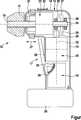
Weitere Vorteile, Merkmale und Einzelheiten der Erfindung ergeben sich aus der nachfolgenden Beschreibung bevorzugter Ausführungsbeispiele sowie anhand der Zeichnung. Diese zeigt in der einzigen Figur einen vereinfachten Längsschnitt durch eine erfindungsgemäße Handwerkzeugmaschine.Further advantages, features and details of the invention will become apparent from the following description of preferred embodiments and from the drawing. This shows in the single figure a simplified longitudinal section through a hand tool according to the invention.
In der einzigen Figur ist eine Handwerkzeugmaschine
Die Handwerkzeugmaschine
Auf der dem ersten Gehäusebereich
Die Antriebswelle
Der Antriebsmotor
Die Längsachse
Auf der dem ersten Gehäusebereich
Die Schalteinrichtung
Die soweit beschriebene Handwerkzeugmaschine
Claims (8)
Translated fromGermanPriority Applications (5)
| Application Number | Priority Date | Filing Date | Title |
|---|---|---|---|
| DE102010063069ADE102010063069A1 (en) | 2010-12-14 | 2010-12-14 | Hand tool, in particular drill or Schraubbohrmaschine |
| CN201110414292XACN102554886A (en) | 2010-12-14 | 2011-12-13 | Handheld power tool, in particular power drill or power screwdriver |
| US13/325,025US20120145427A1 (en) | 2010-12-14 | 2011-12-13 | Handheld Power Tool, in Particular Power Drill or Power Screwdriver |
| GB1121464.0AGB2486566B (en) | 2010-12-14 | 2011-12-13 | Motor location in a power handtool |
| RU2011150618/02ARU2011150618A (en) | 2010-12-14 | 2011-12-13 | MANUAL MACHINE, BEFORE ANY DRILL OR DRILL DRILL |
Applications Claiming Priority (1)
| Application Number | Priority Date | Filing Date | Title |
|---|---|---|---|
| DE102010063069ADE102010063069A1 (en) | 2010-12-14 | 2010-12-14 | Hand tool, in particular drill or Schraubbohrmaschine |
Publications (1)
| Publication Number | Publication Date |
|---|---|
| DE102010063069A1true DE102010063069A1 (en) | 2012-06-14 |
Family
ID=45560432
Family Applications (1)
| Application Number | Title | Priority Date | Filing Date |
|---|---|---|---|
| DE102010063069AWithdrawnDE102010063069A1 (en) | 2010-12-14 | 2010-12-14 | Hand tool, in particular drill or Schraubbohrmaschine |
Country Status (5)
| Country | Link |
|---|---|
| US (1) | US20120145427A1 (en) |
| CN (1) | CN102554886A (en) |
| DE (1) | DE102010063069A1 (en) |
| GB (1) | GB2486566B (en) |
| RU (1) | RU2011150618A (en) |
Cited By (1)
| Publication number | Priority date | Publication date | Assignee | Title |
|---|---|---|---|---|
| DE102022206703A1 (en) | 2022-06-30 | 2024-01-04 | Robert Bosch Gesellschaft mit beschränkter Haftung | Machine tool device, machine tool and machine tool system |
Families Citing this family (6)
| Publication number | Priority date | Publication date | Assignee | Title |
|---|---|---|---|---|
| DE102012221748A1 (en)* | 2012-11-28 | 2014-05-28 | Robert Bosch Gmbh | Hand tool |
| DE102012221758A1 (en) | 2012-11-28 | 2014-05-28 | Robert Bosch Gmbh | Hand tool |
| EP2842697A1 (en)* | 2013-09-02 | 2015-03-04 | HILTI Aktiengesellschaft | Manual tool machine |
| DE102014211046A1 (en)* | 2014-06-10 | 2015-12-17 | Robert Bosch Gmbh | System comprising at least one electronically commutated electric motor of a defined size and a rechargeable battery of at least one voltage class |
| CN111587094A (en)* | 2018-01-10 | 2020-08-25 | 柯惠Lp公司 | Robotic surgical assembly and its adapter assembly |
| DE202020104161U1 (en)* | 2020-07-20 | 2021-10-21 | C. & E. Fein Gmbh | drilling machine |
Citations (3)
| Publication number | Priority date | Publication date | Assignee | Title |
|---|---|---|---|---|
| DE4019894A1 (en)* | 1989-07-15 | 1991-04-11 | Ceka Elektrowerkzeuge Ag & Co | Hand held electric power tool with pistol grip handle - has motor and main weight concentrated in handle with short tool spindle for improved location and drive control via geared transmission |
| DE19939171A1 (en)* | 1999-08-20 | 2001-03-08 | Bosch Gmbh Robert | Hand tool |
| DE202004009168U1 (en)* | 2004-06-08 | 2004-10-14 | Mobiletron Electronics Co., Ltd., Ta-Ya | Angle type electric hand tool |
Family Cites Families (24)
| Publication number | Priority date | Publication date | Assignee | Title |
|---|---|---|---|---|
| US2155082A (en)* | 1937-03-23 | 1939-04-18 | Black & Decker Mfg Co | Portable electric tool and casing |
| US2710000A (en)* | 1952-02-19 | 1955-06-07 | Cromer Jeremiah Keith | Cutting instrument |
| US3109238A (en)* | 1961-11-28 | 1963-11-05 | Samuel B Marks | Portable dental drill |
| US3905429A (en)* | 1974-06-10 | 1975-09-16 | Alfred H Berger | Battery powered hand tool |
| US4217964A (en)* | 1979-01-02 | 1980-08-19 | Stryker Corporation | Forward and reverse rotary tool |
| US4347450A (en)* | 1980-12-10 | 1982-08-31 | Colligan Wallace M | Portable power tool |
| US4461305A (en)* | 1981-09-04 | 1984-07-24 | Cibley Leonard J | Automated biopsy device |
| US4462467A (en)* | 1981-11-09 | 1984-07-31 | Hilti Aktiengesellschaft | Percussion drill machine |
| DE4019895C2 (en)* | 1990-06-22 | 1999-04-08 | Ceka Elektrowerkzeuge Ag & Co | Method and device for controlling the operation of handheld electrical devices |
| US5784934A (en)* | 1997-01-30 | 1998-07-28 | Shinano Pneumatic Industries, Inc. | Ratchet wrench with pivotable head |
| US6102632A (en)* | 1998-04-23 | 2000-08-15 | Black & Decker Inc. | Two speed right angle drill |
| US6089331A (en)* | 1998-08-06 | 2000-07-18 | Christ; Joseph T. | Apparatus and method for converting the drive direction axis of a rotational driving source |
| US6655473B1 (en)* | 2002-12-31 | 2003-12-02 | Ying Fang Chi | Hand tool with an adjustable rotational speed and torsion force |
| JP2004249399A (en)* | 2003-02-20 | 2004-09-09 | Makita Corp | Angled power tool |
| US7156187B1 (en)* | 2005-05-13 | 2007-01-02 | Joel Townsan | Electric hand screwdriver with adjustable head |
| DE102006023187B4 (en)* | 2005-05-17 | 2020-02-27 | Milwaukee Electric Tool Corp. | Method for operating a battery charger and a combination comprising a battery and a battery charger |
| CN101300732B (en)* | 2005-11-04 | 2011-02-23 | 罗伯特·博世有限公司 | Drill with solid state speed control and method of operating |
| DE102006048315A1 (en)* | 2006-10-12 | 2008-04-17 | Robert Bosch Gmbh | Hand tool, in particular electric scissors |
| US7779931B2 (en)* | 2006-11-10 | 2010-08-24 | Joel Townsan | Electric hand screwdriver with adjustable head |
| DE102006054288A1 (en)* | 2006-11-17 | 2008-05-21 | A & M Electric Tools Gmbh | Rotary Hammer |
| CN101224571B (en)* | 2007-01-19 | 2013-07-31 | 苏州宝时得电动工具有限公司 | Hand-held electric tool |
| CN201179649Y (en)* | 2008-03-28 | 2009-01-14 | 南京德朔实业有限公司 | Electric tools |
| US8631880B2 (en)* | 2009-04-30 | 2014-01-21 | Black & Decker Inc. | Power tool with impact mechanism |
| CN101837583B (en)* | 2010-05-11 | 2012-10-10 | 南京德朔实业有限公司 | Portable angular tool |
- 2010
- 2010-12-14DEDE102010063069Apatent/DE102010063069A1/ennot_activeWithdrawn
- 2011
- 2011-12-13CNCN201110414292XApatent/CN102554886A/enactivePending
- 2011-12-13USUS13/325,025patent/US20120145427A1/ennot_activeAbandoned
- 2011-12-13RURU2011150618/02Apatent/RU2011150618A/ennot_activeApplication Discontinuation
- 2011-12-13GBGB1121464.0Apatent/GB2486566B/ennot_activeExpired - Fee Related
Patent Citations (3)
| Publication number | Priority date | Publication date | Assignee | Title |
|---|---|---|---|---|
| DE4019894A1 (en)* | 1989-07-15 | 1991-04-11 | Ceka Elektrowerkzeuge Ag & Co | Hand held electric power tool with pistol grip handle - has motor and main weight concentrated in handle with short tool spindle for improved location and drive control via geared transmission |
| DE19939171A1 (en)* | 1999-08-20 | 2001-03-08 | Bosch Gmbh Robert | Hand tool |
| DE202004009168U1 (en)* | 2004-06-08 | 2004-10-14 | Mobiletron Electronics Co., Ltd., Ta-Ya | Angle type electric hand tool |
Cited By (1)
| Publication number | Priority date | Publication date | Assignee | Title |
|---|---|---|---|---|
| DE102022206703A1 (en) | 2022-06-30 | 2024-01-04 | Robert Bosch Gesellschaft mit beschränkter Haftung | Machine tool device, machine tool and machine tool system |
Also Published As
| Publication number | Publication date |
|---|---|
| US20120145427A1 (en) | 2012-06-14 |
| GB201121464D0 (en) | 2012-01-25 |
| RU2011150618A (en) | 2013-06-20 |
| GB2486566B (en) | 2014-12-17 |
| GB2486566A (en) | 2012-06-20 |
| CN102554886A (en) | 2012-07-11 |
Similar Documents
| Publication | Publication Date | Title |
|---|---|---|
| DE102010063069A1 (en) | Hand tool, in particular drill or Schraubbohrmaschine | |
| DE102009054930B4 (en) | drilling machine | |
| DE112009005520B4 (en) | reciprocating saw | |
| EP1924407B1 (en) | Portable power drill with gearbox | |
| EP2467238B1 (en) | Portable machine tool switching unit | |
| DE102011010745A1 (en) | Machine tool with a reciprocating output spindle | |
| DE102011004495A1 (en) | Hand tool | |
| DE102007018464A1 (en) | Motor driven machine tool | |
| DE102007018466A1 (en) | Motor driven machine tool | |
| EP3638457B1 (en) | Hand-held power tool | |
| DE102005041447A1 (en) | Hammer drill, comprises intermediate shaft designed as plain cylindrical element holding driving wheel, driven wheel, and slide bearing | |
| DE202020103996U1 (en) | Electric hammer | |
| DE102006059076A1 (en) | Schlagwerk an electric hand tool machine | |
| DE102007050307A1 (en) | Hand tool | |
| DE102008042354A1 (en) | Hand tool with a switchable gearbox | |
| DE102004024279A1 (en) | Universal saw | |
| DE10236135B4 (en) | Portable, hand-held tool | |
| WO2009083307A1 (en) | Hand power tool having a gear arrangement comprising at least one pivotably supported intermediate shaft | |
| EP2234771A1 (en) | Portable power tool | |
| DE19652751C2 (en) | Hand machine tool with a blower | |
| DE202007004931U1 (en) | Hand tool | |
| EP2142344A1 (en) | Hand machine tool | |
| EP2451615A1 (en) | Hammer-drilling and/or cutting device | |
| DE102014206244A1 (en) | Hand tool | |
| EP2011608A1 (en) | Hand tool with friction clutch |
Legal Events
| Date | Code | Title | Description |
|---|---|---|---|
| R163 | Identified publications notified | ||
| R012 | Request for examination validly filed | Effective date:20130222 | |
| R016 | Response to examination communication | ||
| R119 | Application deemed withdrawn, or ip right lapsed, due to non-payment of renewal fee |