DE102010063019A1 - Wiper blade adapter device - Google Patents
Wiper blade adapter deviceDownload PDFInfo
- Publication number
- DE102010063019A1 DE102010063019A1DE102010063019ADE102010063019ADE102010063019A1DE 102010063019 A1DE102010063019 A1DE 102010063019A1DE 102010063019 ADE102010063019 ADE 102010063019ADE 102010063019 ADE102010063019 ADE 102010063019ADE 102010063019 A1DE102010063019 A1DE 102010063019A1
- Authority
- DE
- Germany
- Prior art keywords
- wiper blade
- blade adapter
- coupling element
- adapter device
- coupling
- Prior art date
- Legal status (The legal status is an assumption and is not a legal conclusion. Google has not performed a legal analysis and makes no representation as to the accuracy of the status listed.)
- Ceased
Links
- 230000008878couplingEffects0.000claimsabstractdescription53
- 238000010168coupling processMethods0.000claimsabstractdescription53
- 238000005859coupling reactionMethods0.000claimsabstractdescription53
- 238000004519manufacturing processMethods0.000description2
- 238000000034methodMethods0.000description2
- BUHVIAUBTBOHAG-FOYDDCNASA-N(2r,3r,4s,5r)-2-[6-[[2-(3,5-dimethoxyphenyl)-2-(2-methylphenyl)ethyl]amino]purin-9-yl]-5-(hydroxymethyl)oxolane-3,4-diolChemical compoundCOC1=CC(OC)=CC(C(CNC=2C=3N=CN(C=3N=CN=2)[C@H]2[C@@H]([C@H](O)[C@@H](CO)O2)O)C=2C(=CC=CC=2)C)=C1BUHVIAUBTBOHAG-FOYDDCNASA-N0.000description1
- 239000000853adhesiveSubstances0.000description1
- 230000001070adhesive effectEffects0.000description1
- 230000005489elastic deformationEffects0.000description1
- 238000001746injection mouldingMethods0.000description1
- 238000000926separation methodMethods0.000description1
- 238000003466weldingMethods0.000description1
Images


Classifications
- B—PERFORMING OPERATIONS; TRANSPORTING
- B60—VEHICLES IN GENERAL
- B60S—SERVICING, CLEANING, REPAIRING, SUPPORTING, LIFTING, OR MANOEUVRING OF VEHICLES, NOT OTHERWISE PROVIDED FOR
- B60S1/00—Cleaning of vehicles
- B60S1/02—Cleaning windscreens, windows or optical devices
- B60S1/04—Wipers or the like, e.g. scrapers
- B60S1/32—Wipers or the like, e.g. scrapers characterised by constructional features of wiper blade arms or blades
- B60S1/38—Wiper blades
- B60S1/3848—Flat-type wiper blade, i.e. without harness
- B60S1/3849—Connectors therefor; Connection to wiper arm; Attached to blade
- B—PERFORMING OPERATIONS; TRANSPORTING
- B60—VEHICLES IN GENERAL
- B60S—SERVICING, CLEANING, REPAIRING, SUPPORTING, LIFTING, OR MANOEUVRING OF VEHICLES, NOT OTHERWISE PROVIDED FOR
- B60S1/00—Cleaning of vehicles
- B60S1/02—Cleaning windscreens, windows or optical devices
- B60S1/04—Wipers or the like, e.g. scrapers
- B60S1/32—Wipers or the like, e.g. scrapers characterised by constructional features of wiper blade arms or blades
- B60S1/40—Connections between blades and arms
- B60S1/4003—Multi-purpose connections for two or more kinds of arm ends
- B—PERFORMING OPERATIONS; TRANSPORTING
- B60—VEHICLES IN GENERAL
- B60S—SERVICING, CLEANING, REPAIRING, SUPPORTING, LIFTING, OR MANOEUVRING OF VEHICLES, NOT OTHERWISE PROVIDED FOR
- B60S1/00—Cleaning of vehicles
- B60S1/02—Cleaning windscreens, windows or optical devices
- B60S1/04—Wipers or the like, e.g. scrapers
- B60S1/32—Wipers or the like, e.g. scrapers characterised by constructional features of wiper blade arms or blades
- B60S1/38—Wiper blades
- B60S1/3848—Flat-type wiper blade, i.e. without harness
- B60S1/3849—Connectors therefor; Connection to wiper arm; Attached to blade
- B60S1/3865—Connectors having an integral pivot pin for connection with the wiper arm
- B60S1/3867—Connectors having an integral pivot pin for connection with the wiper arm pin formed on the interior of side walls
- B—PERFORMING OPERATIONS; TRANSPORTING
- B60—VEHICLES IN GENERAL
- B60S—SERVICING, CLEANING, REPAIRING, SUPPORTING, LIFTING, OR MANOEUVRING OF VEHICLES, NOT OTHERWISE PROVIDED FOR
- B60S1/00—Cleaning of vehicles
- B60S1/02—Cleaning windscreens, windows or optical devices
- B60S1/04—Wipers or the like, e.g. scrapers
- B60S1/32—Wipers or the like, e.g. scrapers characterised by constructional features of wiper blade arms or blades
- B60S1/38—Wiper blades
- B60S1/3848—Flat-type wiper blade, i.e. without harness
- B60S1/3849—Connectors therefor; Connection to wiper arm; Attached to blade
- B60S1/387—Connectors therefor; Connection to wiper arm; Attached to blade the connector being suitable for receiving different types of adapter
- B—PERFORMING OPERATIONS; TRANSPORTING
- B60—VEHICLES IN GENERAL
- B60S—SERVICING, CLEANING, REPAIRING, SUPPORTING, LIFTING, OR MANOEUVRING OF VEHICLES, NOT OTHERWISE PROVIDED FOR
- B60S1/00—Cleaning of vehicles
- B60S1/02—Cleaning windscreens, windows or optical devices
- B60S1/04—Wipers or the like, e.g. scrapers
- B60S1/32—Wipers or the like, e.g. scrapers characterised by constructional features of wiper blade arms or blades
- B60S1/38—Wiper blades
- B60S1/3848—Flat-type wiper blade, i.e. without harness
- B60S1/3849—Connectors therefor; Connection to wiper arm; Attached to blade
- B60S1/3851—Mounting of connector to blade assembly
- B—PERFORMING OPERATIONS; TRANSPORTING
- B60—VEHICLES IN GENERAL
- B60S—SERVICING, CLEANING, REPAIRING, SUPPORTING, LIFTING, OR MANOEUVRING OF VEHICLES, NOT OTHERWISE PROVIDED FOR
- B60S1/00—Cleaning of vehicles
- B60S1/02—Cleaning windscreens, windows or optical devices
- B60S1/04—Wipers or the like, e.g. scrapers
- B60S1/32—Wipers or the like, e.g. scrapers characterised by constructional features of wiper blade arms or blades
- B60S1/38—Wiper blades
- B60S1/3848—Flat-type wiper blade, i.e. without harness
- B60S1/3849—Connectors therefor; Connection to wiper arm; Attached to blade
- B60S1/386—Connectors therefor; Connection to wiper arm; Attached to blade made in two halves
Landscapes
- Engineering & Computer Science (AREA)
- Mechanical Engineering (AREA)
- Ink Jet (AREA)
- Cleaning Implements For Floors, Carpets, Furniture, Walls, And The Like (AREA)
- Snaps, Bayonet Connections, Set Pins, And Snap Rings (AREA)
- Brushes (AREA)
- Paper (AREA)
Abstract
Translated fromGermanDescription
Translated fromGermanStand der TechnikState of the art
Aus der Druckschrift
Offenbarung der ErfindungDisclosure of the invention
Die Erfindung geht aus von einer Wischblattadaptervorrichtung, insbesondere für ein Wischblatt eines Kraftfahrzeugs, mit einem Wischblattadapter und einem Kopplungselement zur Kopplung des Wischblattadapters an einem Wischblatt.The invention relates to a wiper blade adapter device, in particular for a wiper blade of a motor vehicle, with a wiper blade adapter and a coupling element for coupling the wiper blade adapter to a wiper blade.
Es wird vorgeschlagen, dass der Wischblattadapter mit dem Kopplungselement lösbar verbunden ist, wodurch die Wischblattadaptervorrichtung besonders einfach montiert und/oder austauschbar ausgebildet werden kann. Unter einem „Wischblattadapter” soll in diesem Zusammenhang insbesondere ein Adapter verstanden werden, der dazu vorgesehen ist, einen Kopplungsbereich der Wischblattadaptervorrichtung für eine Kopplung mit einem Wischarm bereitzustellen. Unter einem „Kopplungselement” soll in diesem Zusammenhang insbesondere ein Element verstanden werden, das dazu vorgesehen ist, den Wischblattadapter mit einem Bauteil eines Wischblatts zu koppeln, wie insbesondere mit einem leistenförmigen Trägerelement. Unter „lösbar” soll in diesem Zusammenhang insbesondere „zerstörungsfrei trennbar” verstanden werden. Besonders vorteilhaft ist der Wischblattadapter werkzeuglos lösbar und/oder befestigbar. Unter „vorgesehen” soll dabei in diesem Zusammenhang insbesondere speziell ausgelegt und/oder ausgestattet verstanden werden.It is proposed that the wiper blade adapter is releasably connected to the coupling element, whereby the wiper blade adapter device can be designed to be particularly easy to mount and / or replaceable. In this context, a "wiper blade adapter" is to be understood in particular to mean an adapter which is provided to provide a coupling region of the wiper blade adapter device for coupling to a wiper arm. A "coupling element" is to be understood in this context, in particular an element which is intended to couple the wiper blade adapter with a component of a wiper blade, in particular with a strip-shaped carrier element. By "solvable" is meant in this context in particular "non-destructively separable". Particularly advantageously, the wiper blade adapter can be detached and / or fastened without tools. In this context, "intended" should be understood to mean in particular specially designed and / or equipped.
Weist das Kopplungselement zumindest ein Rastmittel auf, das dazu vorgesehen ist, in einem montierten Zustand einen Formschluss mit dem Wischblattadapter zu bilden, kann eine einfach zu lösende und verschleißarme Verbindung zwischen dem Wischblattadapter und dem Kopplungselement hergestellt werden. Unter einem „Rastmittel” soll in diesem Zusammenhang insbesondere ein Mittel verstanden werden, das dazu vorgesehen ist, mittels eines federelastischen Bauteils, das zur Montage elastisch ausgelenkt wird, eine Rastverbindung herzustellen.If the coupling element has at least one latching means which is intended to form a positive connection with the wiper blade adapter in an assembled state, an easily detachable and low-wear connection between the wiper blade adapter and the coupling element can be produced. In this context, a "locking means" should be understood to mean, in particular, a means which is intended to produce a latching connection by means of a spring-elastic component which is elastically deflected for mounting.
Ist das Rastmittel an einem freien Ende des Kopplungselements angeordnet, kann das Kopplungselement besonders stabil ausgebildet werden. Unter einem „freien Ende” soll in diesem Zusammenhang insbesondere ein Ende einer Hauptlängserstreckung eines Elements verstanden werden. Unter einer „Hauptlängserstreckung” soll in diesem Zusammenhang insbesondere eine größtmögliche Erstreckung verstanden werden. Unter einer „Erstreckung” eines Elements soll in diesem Zusammenhang insbesondere ein maximaler Abstand zweier Punkte einer senkrechten Projektion des Elements auf eine Ebene verstanden werden.If the latching means is arranged at a free end of the coupling element, the coupling element can be made particularly stable. In this context, a "free end" should be understood as meaning, in particular, an end of a main longitudinal extension of an element. In this context, a "main longitudinal extension" is to be understood as meaning, in particular, the greatest possible extension. In this context, an "extension" of an element should be understood as meaning in particular a maximum distance between two points of a vertical projection of the element onto a plane.
Der Wischblattadapter kann besonders einfach und sicher montiert werden, wenn das Kopplungselement eine Längsführungseinheit aufweist, die dazu vorgesehen ist, den Wischblattadapter bei einer Montage bei einer Aufschubbewegung zu führen. Unter einer „Längsführungseinheit” soll in diesem Zusammenhang insbesondere eine Einheit verstanden werden, die dazu vorgesehen ist, eine Führung eines Trägerelements in einer Längsrichtung bereitzustellen. Unter einer „Längsrichtung” soll in diesem Zusammenhang insbesondere eine Richtung verstanden werden, die sich zumindest im Wesentlichen parallel zu einer Hauptlängserstreckung des Trägerelements erstreckt. Unter „im Wesentlichen” soll in diesem Zusammenhang insbesondere eine Abweichung von weniger als 10°, bevorzugt weniger als 5° verstanden werden. In einer weiteren Ausgestaltung der Erfindung wird vorgeschlagen, dass die Längsführungseinheit zumindest ein Längsführungselement aufweist, das einstückig mit einem Grundkörper des Kopplungselements ausgebildet ist, wodurch eine stabile Aufnahme des Wischblattadapters erreicht werden kann. Unter einem „Längsführungselement” soll in diesem Zusammenhang insbesondere ein Führungselement verstanden werden, welches sich zumindest im Wesentlichen parallel zu einer Längsrichtung des Kopplungselements erstreckt. Unter „einstückig” soll insbesondere stoffschlüssig verbunden, wie beispielsweise durch einen Schweißprozess und/oder Klebeprozess usw., und besonders vorteilhaft angeformt verstanden werden, wie durch die Herstellung aus einem Guss und/oder durch die Herstellung in einem Ein- oder Mehrkomponentenspritzgussverfahren.The wiper blade adapter can be mounted in a particularly simple and secure manner if the coupling element has a longitudinal guide unit which is provided to guide the wiper blade adapter during assembly during a push-on movement. A "longitudinal guide unit" should be understood in this context, in particular a unit which is intended to provide a guide of a support member in a longitudinal direction. In this context, a "longitudinal direction" should in particular be understood to mean a direction which extends at least substantially parallel to a main longitudinal extension of the carrier element. In this context, "substantially" is to be understood as meaning, in particular, a deviation of less than 10 °, preferably less than 5 °. In a further embodiment of the invention it is proposed that the longitudinal guide unit has at least one longitudinal guide element, which is formed integrally with a base body of the coupling element, whereby a stable reception of the wiper blade adapter can be achieved. In this context, a "longitudinal guide element" is to be understood as meaning, in particular, a guide element which extends at least substantially parallel to a longitudinal direction of the coupling element. By "in one piece" should be understood in particular as being materially bonded, as for example by a welding process and / or adhesive process, etc., and particularly advantageously formed, such as by the production from a cast and / or by the production in a single or multi-component injection molding process.
Ferner wird vorgeschlagen, dass das Rastmittel im Wesentlichen senkrecht zu einer Auflagefläche des Kopplungselements auslenkbar ist, wodurch eine sichere Ausgestaltung erreicht werden kann.It is also proposed that the locking means is deflected substantially perpendicular to a bearing surface of the coupling element, whereby a secure configuration can be achieved.
In einer weiteren Ausgestaltung der Erfindung wird vorgeschlagen, dass das Rastmittel zumindest ein Federmittel aufweist, das das Kopplungselement in eine Längsrichtung hin abschließt, wodurch das Kopplungselement besonders stabil ausgebildet werden kann.In a further embodiment of the invention, it is proposed that the latching means comprise at least one spring means which closes the coupling element in a longitudinal direction, whereby the coupling element can be made particularly stable.
Ferner wird vorgeschlagen, dass der Wischblattadapter einen Fortsatz aufweist, der in einem montierten Zustand einen Formschluss mit dem Rastmittel bildet. Dadurch kann das Rastmittel an einer besonders großen Anlagefläche anliegen.It is also proposed that the wiper blade adapter has an extension which forms a positive connection with the latching means in an assembled state. As a result, the locking means may rest against a particularly large contact surface.
Zeichnung drawing
Weitere Vorteile ergeben sich aus der folgenden Zeichnungsbeschreibung. In der Zeichnung ist ein Ausführungsbeispiel der Erfindung dargestellt. Die Zeichnung, die Beschreibung und die Ansprüche enthalten zahlreiche Merkmale in Kombination. Der Fachmann wird die Merkmale zweckmäßigerweise auch einzeln betrachten und zu sinnvollen weiteren Kombinationen zusammenfassen.Further advantages emerge from the following description of the drawing. In the drawing, an embodiment of the invention is shown. The drawing, the description and the claims contain numerous features in combination. The person skilled in the art will expediently also consider the features individually and combine them into meaningful further combinations.
Es zeigen:Show it:
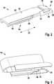
Der Wischblattadapter
Das Kopplungselement
Das Federmittel
Die Rundung
Ferner weist das Kopplungselement
Der Wischblattadapter
Jeder Fortsatz
Um den Wischblattadapter
Das Rastmittel
Der Grundkörper
Um den Wischblattadapter
ZITATE ENTHALTEN IN DER BESCHREIBUNG QUOTES INCLUDE IN THE DESCRIPTION
Diese Liste der vom Anmelder aufgeführten Dokumente wurde automatisiert erzeugt und ist ausschließlich zur besseren Information des Lesers aufgenommen. Die Liste ist nicht Bestandteil der deutschen Patent- bzw. Gebrauchsmusteranmeldung. Das DPMA übernimmt keinerlei Haftung für etwaige Fehler oder Auslassungen.This list of the documents listed by the applicant has been generated automatically and is included solely for the better information of the reader. The list is not part of the German patent or utility model application. The DPMA assumes no liability for any errors or omissions.
Zitierte PatentliteraturCited patent literature
- DE 102007058091 A1[0001]DE 102007058091 A1[0001]
Claims (10)
Translated fromGermanPriority Applications (10)
| Application Number | Priority Date | Filing Date | Title |
|---|---|---|---|
| DE102010063019ADE102010063019A1 (en) | 2010-12-14 | 2010-12-14 | Wiper blade adapter device |
| JP2013543602AJP2013545669A (en) | 2010-12-14 | 2011-11-15 | Wiper blade adapter device |
| US13/994,683US9227598B2 (en) | 2010-12-14 | 2011-11-15 | Wiper blade adaptor device |
| PCT/EP2011/070182WO2012079893A1 (en) | 2010-12-14 | 2011-11-15 | Wiper blade adaptor device |
| AU2011344667AAU2011344667B2 (en) | 2010-12-14 | 2011-11-15 | Wiper blade adaptor device |
| RU2013132352/11ARU2601516C2 (en) | 2010-12-14 | 2011-11-15 | Adapter for fastening of wiper blade to its lever |
| BR112013014775ABR112013014775A2 (en) | 2010-12-14 | 2011-11-15 | ADAPTER DEVICE FOR CLEANER BLADE |
| EP11784645.1AEP2651714A1 (en) | 2010-12-14 | 2011-11-15 | Wiper blade adaptor device |
| KR1020137011517AKR101490873B1 (en) | 2010-12-14 | 2011-11-15 | Wiper blade adaptor device |
| CN201180059856.0ACN103249609B (en) | 2010-12-14 | 2011-11-15 | Wiper blade adapter with its coupling element and wiper blade adapter |
Applications Claiming Priority (1)
| Application Number | Priority Date | Filing Date | Title |
|---|---|---|---|
| DE102010063019ADE102010063019A1 (en) | 2010-12-14 | 2010-12-14 | Wiper blade adapter device |
Publications (1)
| Publication Number | Publication Date |
|---|---|
| DE102010063019A1true DE102010063019A1 (en) | 2012-06-14 |
Family
ID=44993557
Family Applications (1)
| Application Number | Title | Priority Date | Filing Date |
|---|---|---|---|
| DE102010063019ACeasedDE102010063019A1 (en) | 2010-12-14 | 2010-12-14 | Wiper blade adapter device |
Country Status (10)
| Country | Link |
|---|---|
| US (1) | US9227598B2 (en) |
| EP (1) | EP2651714A1 (en) |
| JP (1) | JP2013545669A (en) |
| KR (1) | KR101490873B1 (en) |
| CN (1) | CN103249609B (en) |
| AU (1) | AU2011344667B2 (en) |
| BR (1) | BR112013014775A2 (en) |
| DE (1) | DE102010063019A1 (en) |
| RU (1) | RU2601516C2 (en) |
| WO (1) | WO2012079893A1 (en) |
Cited By (1)
| Publication number | Priority date | Publication date | Assignee | Title |
|---|---|---|---|---|
| FR3049917A1 (en)* | 2016-04-12 | 2017-10-13 | Valeo Systemes Dessuyage | CAP COMPRISING A CONNECTOR FOR A WIPER BLADE OF A MOTOR VEHICLE |
Families Citing this family (19)
| Publication number | Priority date | Publication date | Assignee | Title |
|---|---|---|---|---|
| US20130227809A1 (en) | 2012-02-24 | 2013-09-05 | Pylon Manufacturing Corp. | Wiper blade |
| US9457768B2 (en) | 2011-04-21 | 2016-10-04 | Pylon Manufacturing Corp. | Vortex damping wiper blade |
| MX345011B (en) | 2011-07-28 | 2017-01-11 | Pylon Mfg Corp | Windshield wiper adapter, connector and assembly. |
| US9108595B2 (en) | 2011-07-29 | 2015-08-18 | Pylon Manufacturing Corporation | Windshield wiper connector |
| US10723322B2 (en) | 2012-02-24 | 2020-07-28 | Pylon Manufacturing Corp. | Wiper blade with cover |
| US20130219649A1 (en) | 2012-02-24 | 2013-08-29 | Pylon Manufacturing Corp. | Wiper blade |
| US10829092B2 (en) | 2012-09-24 | 2020-11-10 | Pylon Manufacturing Corp. | Wiper blade with modular mounting base |
| US9555775B2 (en) | 2013-03-15 | 2017-01-31 | Illinois Tool Works Inc. | Connectors and connector kit for attachment of a windshield wiper blade to multiple types of windshield wiper arms |
| US10166951B2 (en) | 2013-03-15 | 2019-01-01 | Pylon Manufacturing Corp. | Windshield wiper connector |
| US9511748B2 (en) | 2013-03-15 | 2016-12-06 | Illinois Tool Works Inc. | Universal connector for attachment of a windshield wiper blade with multiple types of windshield wiper arms |
| USD727238S1 (en) | 2013-12-13 | 2015-04-21 | Illinois Tool Works Inc. | Cover used for windshield wiper connectors |
| US9505380B2 (en) | 2014-03-07 | 2016-11-29 | Pylon Manufacturing Corp. | Windshield wiper connector and assembly |
| USD848139S1 (en) | 2015-05-15 | 2019-05-14 | Oliver Joen-An Ma | Umbrella frame |
| WO2017075066A1 (en) | 2015-10-26 | 2017-05-04 | Pylon Manufacturing Corp. | Wiper blade |
| EP3458315B1 (en) | 2016-05-19 | 2021-09-08 | Pylon Manufacturing Corp. | Windshield wiper blade |
| WO2017201470A1 (en) | 2016-05-19 | 2017-11-23 | Pylon Manufacturing Corp. | Windshield wiper connector |
| WO2017201485A1 (en) | 2016-05-19 | 2017-11-23 | Pylon Manufacturing Corp. | Windshield wiper connector |
| US11040705B2 (en) | 2016-05-19 | 2021-06-22 | Pylon Manufacturing Corp. | Windshield wiper connector |
| WO2017201458A1 (en) | 2016-05-19 | 2017-11-23 | Pylon Manufacturing Corp. | Windshield wiper connector |
Citations (1)
| Publication number | Priority date | Publication date | Assignee | Title |
|---|---|---|---|---|
| DE102007058091A1 (en) | 2007-12-03 | 2009-06-04 | Robert Bosch Gmbh | wiper blade |
Family Cites Families (18)
| Publication number | Priority date | Publication date | Assignee | Title |
|---|---|---|---|---|
| US3179969A (en)* | 1963-10-04 | 1965-04-27 | Tridon Mfg Ltd | Automobile windshield wiper backing members |
| US3254358A (en)* | 1963-11-12 | 1966-06-07 | Ralph H Wise | Windshield wiper connector |
| DE19935860A1 (en)* | 1999-07-30 | 2001-02-01 | Bosch Gmbh Robert | Wiper device for windows of motor vehicles with a wiper arm that can be moved between reversal positions and is loaded to the window |
| FR2879986B1 (en)* | 2004-12-23 | 2008-07-11 | Valeo Systemes Dessuyage | UNIVERSAL FLAT WIPER BLADE AND REMOVABLE CONNECTOR |
| DE102005016485A1 (en)* | 2005-02-03 | 2006-08-10 | Robert Bosch Gmbh | Device for articulating a wiper blade with a wiper arm of a windshield wiper |
| FR2890026B1 (en) | 2005-08-29 | 2008-12-05 | Valeo Systemes Dessuyage | WIPER BLADE COMPRISING A TWO-PART SUPPORT MOUNT |
| FR2890925B1 (en)* | 2005-09-21 | 2009-12-25 | Valeo Systemes Dessuyage | CONNECTOR FOR MOUNTING AND JOINING A WIPER BRUSH ON THE END OF A TRAINING ARM |
| US7861363B2 (en) | 2006-02-02 | 2011-01-04 | Trico Products Corporation | Beam blade windshield wiper assembly having an airfoil |
| DE102006047633A1 (en) | 2006-10-09 | 2008-04-17 | Robert Bosch Gmbh | wiper blade |
| KR100889959B1 (en) | 2007-05-21 | 2009-03-20 | 에이디엠이십일 주식회사 | wiper blade |
| FR2916715B1 (en)* | 2007-05-31 | 2010-02-12 | Valeo Systemes Dessuyage | CONNECTING BASE FOR COOPERATING WITH AN ADAPTER TO FORM WITH THE SAME A MECHANICAL CONNECTOR FOR A WIPER BLADE FOR A MOTOR VEHICLE |
| TWM323417U (en) | 2007-06-01 | 2007-12-11 | Yu-Rung Lin | Non-supporting windshield wiper |
| FR2919555A1 (en) | 2007-07-31 | 2009-02-06 | Valeo Systemes Dessuyage | CONNECTION PLATFORM FOR COOPERATING WITH AN ADAPTER TO FORM THEREFOR WITH A MECHANICAL CONNECTOR FOR A WIPER BLADE FOR A MOTOR VEHICLE |
| FR2924080B1 (en)* | 2007-11-28 | 2010-04-02 | Valeo Systemes Dessuyage | PLATFORM FOR CONNECTING A WIPER BLADE FOR A MOTOR VEHICLE |
| FR2925437B1 (en) | 2007-12-19 | 2009-12-25 | Valeo Systemes Dessuyage | ICE WIPER BLADE COMPRISING A CONNECTOR AND METHOD OF ASSEMBLING SUCH A BROOM |
| KR100918091B1 (en)* | 2008-01-17 | 2009-09-22 | 주식회사 캐프 | Clamping Device for Wiper Blades |
| EP2090479B1 (en) | 2008-02-18 | 2014-11-26 | Federal-Mogul S.a. | Windscreen wiper device |
| DE102008001045A1 (en) | 2008-04-08 | 2009-10-15 | Robert Bosch Gmbh | wiper blade |
- 2010
- 2010-12-14DEDE102010063019Apatent/DE102010063019A1/ennot_activeCeased
- 2011
- 2011-11-15EPEP11784645.1Apatent/EP2651714A1/ennot_activeCeased
- 2011-11-15USUS13/994,683patent/US9227598B2/enactiveActive
- 2011-11-15BRBR112013014775Apatent/BR112013014775A2/enactiveSearch and Examination
- 2011-11-15RURU2013132352/11Apatent/RU2601516C2/ennot_activeIP Right Cessation
- 2011-11-15CNCN201180059856.0Apatent/CN103249609B/enactiveActive
- 2011-11-15JPJP2013543602Apatent/JP2013545669A/enactivePending
- 2011-11-15WOPCT/EP2011/070182patent/WO2012079893A1/enactiveApplication Filing
- 2011-11-15AUAU2011344667Apatent/AU2011344667B2/ennot_activeCeased
- 2011-11-15KRKR1020137011517Apatent/KR101490873B1/ennot_activeExpired - Fee Related
Patent Citations (1)
| Publication number | Priority date | Publication date | Assignee | Title |
|---|---|---|---|---|
| DE102007058091A1 (en) | 2007-12-03 | 2009-06-04 | Robert Bosch Gmbh | wiper blade |
Cited By (1)
| Publication number | Priority date | Publication date | Assignee | Title |
|---|---|---|---|---|
| FR3049917A1 (en)* | 2016-04-12 | 2017-10-13 | Valeo Systemes Dessuyage | CAP COMPRISING A CONNECTOR FOR A WIPER BLADE OF A MOTOR VEHICLE |
Also Published As
| Publication number | Publication date |
|---|---|
| KR101490873B1 (en) | 2015-02-06 |
| RU2601516C2 (en) | 2016-11-10 |
| AU2011344667A1 (en) | 2013-07-11 |
| WO2012079893A1 (en) | 2012-06-21 |
| JP2013545669A (en) | 2013-12-26 |
| KR20130073982A (en) | 2013-07-03 |
| US20130305476A1 (en) | 2013-11-21 |
| CN103249609A (en) | 2013-08-14 |
| EP2651714A1 (en) | 2013-10-23 |
| RU2013132352A (en) | 2015-06-27 |
| CN103249609B (en) | 2016-07-20 |
| AU2011344667B2 (en) | 2016-02-18 |
| BR112013014775A2 (en) | 2023-12-26 |
| US9227598B2 (en) | 2016-01-05 |
Similar Documents
| Publication | Publication Date | Title |
|---|---|---|
| DE102010063019A1 (en) | Wiper blade adapter device | |
| EP0869886B1 (en) | Wiper blade for vehicle window panes | |
| EP2658755B1 (en) | Wiper blade adapter, in particular for a motor vehicle wiper device | |
| EP2697104B1 (en) | Wiper blade adapter device | |
| DE102011005167A1 (en) | Wiper blade adapter, in particular for a motor vehicle wiper device | |
| EP3475128B1 (en) | Wiper blade adapter device | |
| DE102015004645A1 (en) | Filter element, in particular for gas filtration | |
| DE102010064164A1 (en) | Wiper blade adapter, in particular for a motor vehicle windshield wiper device | |
| DE102011079530A1 (en) | wiper device | |
| EP2697103A1 (en) | Wiper blade adapter device | |
| EP2861469B1 (en) | Wiper blade adapter system | |
| DE102012021489A1 (en) | Connection assembly for connecting wiper arm of windscreen wiper of vehicle with wiper blade, has magnet for exerting magnetic attractive force that assists fixing of adapter in functional position while adapter is present on ridge and core | |
| DE102014201211A1 (en) | wiper device | |
| DE102015225375A1 (en) | Suction device for a portable sawing machine | |
| DE102014214131A1 (en) | Adapter device for coupling a wiper blade with a wiper arm | |
| EP2726336A1 (en) | Wiping device | |
| EP2651709A1 (en) | Wiper blade device | |
| EP2731832B1 (en) | Wiper blade adapter unit | |
| DE102015217405B4 (en) | Wiper blade device | |
| EP2734420A1 (en) | Wiper blade adapter system | |
| EP2651713B1 (en) | Method for mounting a wiper blade device | |
| EP3845422B1 (en) | Wiper device, windscreen wiper and mounting method | |
| DE102010062896A1 (en) | Wiper blade device | |
| DE2608605B2 (en) | WIPING DEVICE FOR WINDOWS OF MOTOR VEHICLES | |
| WO2021104823A1 (en) | Wiper blade device, wiper blade and wiper |
Legal Events
| Date | Code | Title | Description |
|---|---|---|---|
| R012 | Request for examination validly filed | ||
| R002 | Refusal decision in examination/registration proceedings | ||
| R003 | Refusal decision now final |