DE102010061822A1 - wiper blade - Google Patents
wiper bladeDownload PDFInfo
- Publication number
- DE102010061822A1 DE102010061822A1DE102010061822ADE102010061822ADE102010061822A1DE 102010061822 A1DE102010061822 A1DE 102010061822A1DE 102010061822 ADE102010061822 ADE 102010061822ADE 102010061822 ADE102010061822 ADE 102010061822ADE 102010061822 A1DE102010061822 A1DE 102010061822A1
- Authority
- DE
- Germany
- Prior art keywords
- guide
- wiper blade
- profiles
- wiper
- spoiler
- Prior art date
- Legal status (The legal status is an assumption and is not a legal conclusion. Google has not performed a legal analysis and makes no representation as to the accuracy of the status listed.)
- Ceased
Links
- 230000007704transitionEffects0.000claimsdescription9
- 239000000945fillerSubstances0.000claimsdescription3
- 238000011144upstream manufacturingMethods0.000claimsdescription3
- 238000010276constructionMethods0.000abstract1
- XLYOFNOQVPJJNP-UHFFFAOYSA-NwaterSubstancesOXLYOFNOQVPJJNP-UHFFFAOYSA-N0.000description14
- 239000007921spraySubstances0.000description5
- 210000000078clawAnatomy0.000description2
- BUHVIAUBTBOHAG-FOYDDCNASA-N(2r,3r,4s,5r)-2-[6-[[2-(3,5-dimethoxyphenyl)-2-(2-methylphenyl)ethyl]amino]purin-9-yl]-5-(hydroxymethyl)oxolane-3,4-diolChemical compoundCOC1=CC(OC)=CC(C(CNC=2C=3N=CN(C=3N=CN=2)[C@H]2[C@@H]([C@H](O)[C@@H](CO)O2)O)C=2C(=CC=CC=2)C)=C1BUHVIAUBTBOHAG-FOYDDCNASA-N0.000description1
- 229910000639Spring steelInorganic materials0.000description1
- 230000015572biosynthetic processEffects0.000description1
- 238000004140cleaningMethods0.000description1
- 230000001771impaired effectEffects0.000description1
- 230000001376precipitating effectEffects0.000description1
- 238000005507sprayingMethods0.000description1
Images


Classifications
- B—PERFORMING OPERATIONS; TRANSPORTING
- B60—VEHICLES IN GENERAL
- B60S—SERVICING, CLEANING, REPAIRING, SUPPORTING, LIFTING, OR MANOEUVRING OF VEHICLES, NOT OTHERWISE PROVIDED FOR
- B60S1/00—Cleaning of vehicles
- B60S1/02—Cleaning windscreens, windows or optical devices
- B60S1/04—Wipers or the like, e.g. scrapers
- B60S1/32—Wipers or the like, e.g. scrapers characterised by constructional features of wiper blade arms or blades
- B60S1/38—Wiper blades
- B60S1/3848—Flat-type wiper blade, i.e. without harness
- B60S1/3874—Flat-type wiper blade, i.e. without harness with a reinforcing vertebra
- B60S1/3875—Flat-type wiper blade, i.e. without harness with a reinforcing vertebra rectangular section
- B60S1/3881—Flat-type wiper blade, i.e. without harness with a reinforcing vertebra rectangular section in additional element, e.g. spoiler
- B—PERFORMING OPERATIONS; TRANSPORTING
- B60—VEHICLES IN GENERAL
- B60S—SERVICING, CLEANING, REPAIRING, SUPPORTING, LIFTING, OR MANOEUVRING OF VEHICLES, NOT OTHERWISE PROVIDED FOR
- B60S1/00—Cleaning of vehicles
- B60S1/02—Cleaning windscreens, windows or optical devices
- B60S1/04—Wipers or the like, e.g. scrapers
- B60S1/32—Wipers or the like, e.g. scrapers characterised by constructional features of wiper blade arms or blades
- B60S1/38—Wiper blades
- B60S1/3806—Means, or measures taken, for influencing the aerodynamic quality of the wiper blades
- B60S1/381—Spoilers mounted on the squeegee or on the vertebra
- B—PERFORMING OPERATIONS; TRANSPORTING
- B60—VEHICLES IN GENERAL
- B60S—SERVICING, CLEANING, REPAIRING, SUPPORTING, LIFTING, OR MANOEUVRING OF VEHICLES, NOT OTHERWISE PROVIDED FOR
- B60S1/00—Cleaning of vehicles
- B60S1/02—Cleaning windscreens, windows or optical devices
- B60S1/04—Wipers or the like, e.g. scrapers
- B60S1/32—Wipers or the like, e.g. scrapers characterised by constructional features of wiper blade arms or blades
- B60S1/38—Wiper blades
- B60S1/3848—Flat-type wiper blade, i.e. without harness
- B60S1/3849—Connectors therefor; Connection to wiper arm; Attached to blade
- B60S1/3863—Connectors having a spoiler
- B—PERFORMING OPERATIONS; TRANSPORTING
- B60—VEHICLES IN GENERAL
- B60S—SERVICING, CLEANING, REPAIRING, SUPPORTING, LIFTING, OR MANOEUVRING OF VEHICLES, NOT OTHERWISE PROVIDED FOR
- B60S1/00—Cleaning of vehicles
- B60S1/02—Cleaning windscreens, windows or optical devices
- B60S1/04—Wipers or the like, e.g. scrapers
- B60S1/32—Wipers or the like, e.g. scrapers characterised by constructional features of wiper blade arms or blades
- B60S1/38—Wiper blades
- B60S1/3806—Means, or measures taken, for influencing the aerodynamic quality of the wiper blades
- B60S1/3808—Spoiler integral with the squeegee
- B—PERFORMING OPERATIONS; TRANSPORTING
- B60—VEHICLES IN GENERAL
- B60S—SERVICING, CLEANING, REPAIRING, SUPPORTING, LIFTING, OR MANOEUVRING OF VEHICLES, NOT OTHERWISE PROVIDED FOR
- B60S1/00—Cleaning of vehicles
- B60S1/02—Cleaning windscreens, windows or optical devices
- B60S1/04—Wipers or the like, e.g. scrapers
- B60S1/32—Wipers or the like, e.g. scrapers characterised by constructional features of wiper blade arms or blades
- B60S1/38—Wiper blades
- B60S1/3848—Flat-type wiper blade, i.e. without harness
- B60S1/3874—Flat-type wiper blade, i.e. without harness with a reinforcing vertebra
- B60S1/3875—Flat-type wiper blade, i.e. without harness with a reinforcing vertebra rectangular section
- B60S1/3879—Flat-type wiper blade, i.e. without harness with a reinforcing vertebra rectangular section placed in side grooves in the squeegee
Landscapes
- Engineering & Computer Science (AREA)
- Mechanical Engineering (AREA)
- Physics & Mathematics (AREA)
- Fluid Mechanics (AREA)
- Quality & Reliability (AREA)
- Body Structure For Vehicles (AREA)
- Window Of Vehicle (AREA)
- Seal Device For Vehicle (AREA)
- Brushes (AREA)
- Vehicle Cleaning, Maintenance, Repair, Refitting, And Outriggers (AREA)
Abstract
Translated fromGermanDescription
Translated fromGermanStand der TechnikState of the art
Die Erfindung geht von einem Wischblatt nach dem Oberbegriff des Anspruchs 1 aus.The invention is based on a wiper blade according to the preamble of claim 1.
Aus der
Aus der
Offenbarung der ErfindungDisclosure of the invention
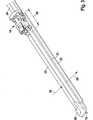
Nach der Erfindung weist das Führungsprofil auf der Abströmseite an seiner nach außen weisenden Längsseite eine Leitrippe auf. Bei der Aufwärtsbewegung während des Betriebs des Wischblatts strömt Wasser auf Grund der aerodynamischen Verhältnisse entlang des antriebsseitigen, inneren Spoilerteils in Richtung auf das Anschlusselement, wo es sich auf Grund von Wirbeln sammelt. Während der Fahrt und der Abwärtsbewegung des Wischblatts gelangt beim Stand der Technik das angesammelte Wasser als Sprühnebel und Wassertropfen auf die Fahrzeugscheibe, wodurch die Wischqualität beeinträchtigt wird. Durch die erfindungsgemäßen Maßnahmen soll verhindert werden, dass sich Wasser im Bereich des Anschlusselements durch Wirbel ansammeln und bei der Abwärtsbewegung des Wischblatts als Sprühnebel oder Tropfen auf die Fahrzeugscheibe gelangen kann. Hierzu dient die erfindungsgemäße Leitrippe in den verschiedenen Ausgestaltungen der Erfindung.According to the invention, the guide profile on the outflow side on its outwardly facing longitudinal side on a guide rib. During the upward movement during operation of the wiper blade, due to the aerodynamic conditions, water flows along the drive-side inner spoiler part in the direction of the connection element, where it collects due to vortices. During the drive and the downward movement of the wiper blade arrives in the prior art, the accumulated water as a spray and drops of water on the vehicle window, whereby the wiping quality is impaired. By means of the measures according to the invention, it is intended to prevent water from collecting in the area of the connection element by means of vortices and, during the downward movement of the wiper blade, to reach the vehicle window as a spray or drops. For this purpose, the guide rib according to the invention serves in the various embodiments of the invention.
Je nach Strömungsverhältnissen am Fahrzeug kann sich die Leitrippe über die gesamte Länge des Wischblatts erstrecken oder sie kann nur an einer oder mehreren kritischen Stellen angeordnet sein. Nach einer Ausgestaltung der Erfindung, bei der zwei Spoilerteile vorgesehen sind, von denen ein inneres Spoilerteil von einem inneren Ende des Wischblatts bis zum Anschlusselement reicht, während sich ein äußeres Spoilerteil von einem äußeren Ende bis zum Anschlusselement erstreckt, wird vorgeschlagen, dass eines oder beide Spoilerteile jeweils ein Führungsprofil mit einer Leitrippe aufweisen. Gleichgültig, ob das innere oder äußere Spoilerteil eine Leitrippe aufweist, kann es vorteilhaft sein, dass dieses über den Bereich des Anschlusselements verlängert ist, sodass das Wasser in diesem Bereich nicht auf die Fahrzeugscheibe tropfen kann.Depending on the flow conditions on the vehicle, the guide rib may extend over the entire length of the wiper blade or it may be arranged only at one or more critical points. According to an embodiment of the invention in which two spoiler parts are provided, of which an inner spoiler part extends from an inner end of the wiper blade to the connecting element, while an outer spoiler part extends from an outer end to the connecting element, it is proposed that one or both Spoilerteile each having a guide profile with a guide rib. Regardless of whether the inner or outer spoiler part has a guide rib, it may be advantageous that this is extended beyond the region of the connecting element, so that the water in this area can not drip onto the vehicle window.
Wenn beide Spoilerteile auf der Abströmseite an den Führungsprofilen Leitrippen aufweisen, ist es zweckmäßig, dass mindestens eine der Leitrippen in dem Bereich des Anschlusselements verlängert ist. Ferner ist es zweckmäßig, dass die Oberseiten der Leitrippen mit den Oberseiten der Führungsprofile bündig abschließen.If both spoiler parts on the downstream side on the guide profiles have guide ribs, it is expedient that at least one of the guide ribs is extended in the region of the connecting element. Furthermore, it is expedient that the tops of the guide ribs are flush with the tops of the guide profiles.
In manchen Fällen mag es ausreichen, dass nur in dem Bereich des Anschlusselements Vorkehrungen getroffen werden, die verhindern, dass Wasser auf die Fahrzeugscheibe tropft. Diese Maßnahmen können allein oder in Verbindung mit den Leitrippen an den Spoilerteilen verwendet werden. So kann zum Beispiel in einem sich über das Anschlusselement erstreckenden Bereich ein Verbindungsstück eine Leitrippe bilden, das sich über Übergänge an die Führungsprofile der Spoilerteile oder an die Leitrippen der Spoilerteile anschließt. Eine solche Leitrippe kann gemäß einer weiteren Ausgestaltung der Erfindung durch eine Verbindungsleiste gebildet werden, die in Längsrichtung zu beiden Seiten des Anschlusselements mittels Halteelementen an den Spoilerteilen angehängt ist, wobei die Verbindungsleiste an die zugeordneten Führungsprofile bzw. an den Leitrippen der Führungsprofile anschließt. Dabei können in einer weiteren Ausgestaltung der Erfindung die Halteelemente als Anschlussprofile für die angrenzenden Spoilerteile ausgebildet sein. Die Anschlussprofile mit angeformten Übergangsprofilen decken das Anschlusselement nach oben zumindest teilweise ab.In some cases it may be sufficient to take precautions only in the area of the connection element, which prevent water from dripping onto the vehicle window. These measures can be used alone or in conjunction with the guide ribs on the spoiler parts. Thus, for example, in a region extending over the connecting element, a connecting piece can form a guide rib, which adjoins transitions to the guide profiles of the spoiler parts or to the guide ribs of the spoiler parts. Such a guide rib can be formed according to a further embodiment of the invention by a connecting strip, which is attached in the longitudinal direction to both sides of the connecting element by means of holding elements on the spoiler parts, wherein the connecting strip connects to the associated guide profiles or to the guide ribs of the guide profiles. In a further embodiment of the invention, the Retaining elements may be formed as connection profiles for the adjacent spoiler parts. The connection profiles with molded transition profiles cover the connection element at least partially upwards.
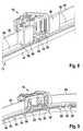
Eine weitere Lösung besteht darin, dass das Anschlusselement mittels Führungsprofilen auf dem Tragelement geführt ist, wobei das auf der Abströmseite vorgesehene Führungsprofil gegenüber dem auf der Anströmseite vorgesehenen Führungsprofil in Längsrichtung verlängert ist und an seiner äußeren Längsseite eine zur Wischlippe weisende Schürze aufweist. Durch das verlängerte Führungsprofil mit seiner Schürze wird die Strömung im Bereich des Anschlusselements über die kritische Stelle geleitet, sodass Turbulenzen weitgehend vermieden werden.Another solution is that the connecting element is guided by means of guide profiles on the support member, wherein the provided on the downstream side guide profile is extended relative to the provided on the inflow side guide profile in the longitudinal direction and on its outer longitudinal side has a wiper lip facing apron. The extended guide profile with its skirt directs the flow in the area of the connection element over the critical point, so that turbulence is largely avoided.
Gemäß einer weiteren Ausgestaltung der Erfindung ist auf der Abströmseite oberhalb der Führungsprofile in Längsrichtung mindestens auf einer Seite des Anschlusselements ein Füllstück vorgesehen, das sich mit einem Übergang an die Abströmseite des zugeordneten Spoilerteils anschließt und bis zur Längsseitenbegrenzung des zugeordneten Führungsprofils oder der zugeordneten Leitrippe reicht. Das Füllstück oder die Füllstücke verhindern, dass sich in diesen kritischen Bereichen Wasser ansammelt oder Wirbel ausbilden, die eine derartige Wasseransammlung bewirken und somit Wasser auf die Fahrzeugscheibe sprühen. Die Strömung in diesen kritischen Bereichen kann ebenfalls durch Stege günstig beeinflusst werden, die gemäß einer weiteren Ausgestaltung der Erfindung an den Führungsprofilen auf der Abströmseite angeformt sind. Die Stege sind in Längsrichtung des Wischblatts mit Abstand zueinander angeordnet und verlaufen etwa senkrecht zur Fahrzeugscheibe. Dabei können die Abstände der Stege unterschiedlich sein und entsprechend dem Anwendungsfall variiert werden. Ebenfalls können die Anzahl der Stege und ihre Neigung zur Fahrzeugscheibe den Einsatzbedingungen angepasst werden.According to a further embodiment of the invention, a filling piece is provided on the outflow side above the guide profiles in the longitudinal direction at least on one side of the connecting element, which adjoins with a transition to the downstream side of the associated spoiler part and extends to the longitudinal side boundary of the associated guide profile or the associated guide rib. The filler or patches prevent water from accumulating in these critical areas or forming vortices that cause such water build-up and thus spray water onto the vehicle window. The flow in these critical regions can likewise be favorably influenced by webs which, according to a further embodiment of the invention, are integrally formed on the guide profiles on the outflow side. The webs are arranged in the longitudinal direction of the wiper blade at a distance from each other and extend approximately perpendicular to the vehicle window. The spacings of the webs can be different and varied according to the application. Also, the number of webs and their inclination to the vehicle window can be adapted to the conditions of use.
Weitere Vorteile ergeben sich aus der folgenden Zeichnungsbeschreibung. In der Zeichnung sind Ausführungsbeispiele der Erfindung dargestellt. Die Zeichnung, die Beschreibung und die Ansprüche enthalten zahlreiche Merkmale in Kombination. Der Fachmann wird die Merkmale zweckmäßigerweise auch einzeln betrachten und zu sinnvollen weiteren Kombinationen zusammenfassen.Further advantages emerge from the following description of the drawing. In the drawings, embodiments of the invention are shown. The drawing, the description and the claims contain numerous features in combination. The person skilled in the art will expediently also consider the features individually and combine them into meaningful further combinations.
Es zeigen:Show it:
Bei einem Wischblatt
Anstelle von zwei Federschienen, kann das Tragelement
In Längsrichtung des Wischblatts
Während einer Aufwärtsbewegung des Wischblatts
Die Ausführungen nach
In vielen Fällen kann es ausreichen, dass nur in dem kritischen Bereich
Die Ausführung nach
Bei der Ausführung nach
Die Ausführung nach
Bei der Ausführung nach
ZITATE ENTHALTEN IN DER BESCHREIBUNG QUOTES INCLUDE IN THE DESCRIPTION
Diese Liste der vom Anmelder aufgeführten Dokumente wurde automatisiert erzeugt und ist ausschließlich zur besseren Information des Lesers aufgenommen. Die Liste ist nicht Bestandteil der deutschen Patent- bzw. Gebrauchsmusteranmeldung. Das DPMA übernimmt keinerlei Haftung für etwaige Fehler oder Auslassungen.This list of the documents listed by the applicant has been generated automatically and is included solely for the better information of the reader. The list is not part of the German patent or utility model application. The DPMA assumes no liability for any errors or omissions.
Zitierte PatentliteraturCited patent literature
- DE 10044913 A1[0002]DE 10044913 A1[0002]
- DE 10120467 A1[0003]DE 10120467 A1[0003]
Claims (15)
Translated fromGermanPriority Applications (8)
| Application Number | Priority Date | Filing Date | Title |
|---|---|---|---|
| DE102010061822ADE102010061822A1 (en) | 2010-11-24 | 2010-11-24 | wiper blade |
| EP11775932.4AEP2643193B1 (en) | 2010-11-24 | 2011-10-17 | Wiper blade |
| RU2013128395/11ARU2578001C2 (en) | 2010-11-24 | 2011-10-17 | Wiper brush |
| ES11775932TES2813094T3 (en) | 2010-11-24 | 2011-10-17 | Wiper blade |
| PCT/EP2011/068102WO2012069258A1 (en) | 2010-11-24 | 2011-10-17 | Wiper blade |
| KR1020137015650AKR101489781B1 (en) | 2010-11-24 | 2011-10-17 | Wiper blade |
| CN201180065769.6ACN103354787B (en) | 2010-11-24 | 2011-10-17 | Windshield wiper blade |
| US13/976,135US9511746B2 (en) | 2010-11-24 | 2011-10-17 | Wiper blade |
Applications Claiming Priority (1)
| Application Number | Priority Date | Filing Date | Title |
|---|---|---|---|
| DE102010061822ADE102010061822A1 (en) | 2010-11-24 | 2010-11-24 | wiper blade |
Publications (1)
| Publication Number | Publication Date |
|---|---|
| DE102010061822A1true DE102010061822A1 (en) | 2012-05-24 |
Family
ID=44872308
Family Applications (1)
| Application Number | Title | Priority Date | Filing Date |
|---|---|---|---|
| DE102010061822ACeasedDE102010061822A1 (en) | 2010-11-24 | 2010-11-24 | wiper blade |
Country Status (8)
| Country | Link |
|---|---|
| US (1) | US9511746B2 (en) |
| EP (1) | EP2643193B1 (en) |
| KR (1) | KR101489781B1 (en) |
| CN (1) | CN103354787B (en) |
| DE (1) | DE102010061822A1 (en) |
| ES (1) | ES2813094T3 (en) |
| RU (1) | RU2578001C2 (en) |
| WO (1) | WO2012069258A1 (en) |
Families Citing this family (10)
| Publication number | Priority date | Publication date | Assignee | Title |
|---|---|---|---|---|
| US20130227809A1 (en) | 2012-02-24 | 2013-09-05 | Pylon Manufacturing Corp. | Wiper blade |
| US9457768B2 (en) | 2011-04-21 | 2016-10-04 | Pylon Manufacturing Corp. | Vortex damping wiper blade |
| US9174609B2 (en) | 2011-04-21 | 2015-11-03 | Pylon Manufacturing Corp. | Wiper blade with cover |
| MX345011B (en) | 2011-07-28 | 2017-01-11 | Pylon Mfg Corp | Windshield wiper adapter, connector and assembly. |
| US9108595B2 (en) | 2011-07-29 | 2015-08-18 | Pylon Manufacturing Corporation | Windshield wiper connector |
| US20130219649A1 (en) | 2012-02-24 | 2013-08-29 | Pylon Manufacturing Corp. | Wiper blade |
| US10829092B2 (en) | 2012-09-24 | 2020-11-10 | Pylon Manufacturing Corp. | Wiper blade with modular mounting base |
| US10166951B2 (en) | 2013-03-15 | 2019-01-01 | Pylon Manufacturing Corp. | Windshield wiper connector |
| US9505380B2 (en) | 2014-03-07 | 2016-11-29 | Pylon Manufacturing Corp. | Windshield wiper connector and assembly |
| US10758092B2 (en) | 2015-06-19 | 2020-09-01 | Mr. Shower Door, Inc. | Water barrier for shower door bottom |
Citations (2)
| Publication number | Priority date | Publication date | Assignee | Title |
|---|---|---|---|---|
| DE10044913A1 (en) | 2000-05-29 | 2001-12-06 | Bosch Gmbh Robert | Wiper blade for cleaning windows, especially of motor vehicles |
| DE10120467A1 (en) | 2001-04-26 | 2002-10-31 | Bosch Gmbh Robert | Wiper blade for cleaning windows, especially of motor vehicles |
Family Cites Families (24)
| Publication number | Priority date | Publication date | Assignee | Title |
|---|---|---|---|---|
| FR2530562B1 (en) | 1982-07-22 | 1987-04-24 | Marchal Equip Auto | WIPER BLADE |
| US5946764A (en)* | 1997-06-05 | 1999-09-07 | Tworzydlo; Wlodzimierz Woytek | Wiper with tiliable substructure and airflow deflectors |
| DE19856300A1 (en)* | 1998-12-07 | 2000-06-08 | Bosch Gmbh Robert | Wiper blade for windows of motor vehicles |
| KR20020016153A (en)* | 2000-08-24 | 2002-03-04 | 김민박,라이문트하이넨 | Wiper blade for an automobile |
| DE10320930A1 (en)* | 2003-05-09 | 2004-11-25 | Volkswagen Ag | Connection device for a wiper blade on the wiper arm of a wiper system |
| DE102005019389A1 (en)* | 2005-04-28 | 2006-11-02 | Robert Bosch Gmbh | Wiper blade for vehicle window pane has covering cap, which comprises opening or recess for angular end of clip, on the side of cap opposing rubber profiled element in the region of connection element |
| FR2885102B1 (en)* | 2005-04-29 | 2016-08-05 | Valeo Systemes Dessuyage | CONNECTOR CONNECTING A WIPER BLADE TO A DRIVE ARM |
| DE102005025542A1 (en)* | 2005-06-01 | 2006-12-07 | Robert Bosch Gmbh | Device for articulating a wiper blade with a wiper arm of a windshield wiper |
| DE102005050569A1 (en)* | 2005-10-21 | 2007-04-26 | Robert Bosch Gmbh | Connecting device for a wiper arm |
| US7861363B2 (en)* | 2006-02-02 | 2011-01-04 | Trico Products Corporation | Beam blade windshield wiper assembly having an airfoil |
| EP1847425B1 (en)* | 2006-04-21 | 2009-11-25 | Federal-Mogul S.A. | A windscreen wiper device |
| DE102006027439A1 (en) | 2006-06-12 | 2007-12-13 | Robert Bosch Gmbh | wiper blade |
| US20080148509A1 (en)* | 2006-12-15 | 2008-06-26 | Bacarella Joseph C | Connectable-disconnectable shroud-connector-adapter |
| US20080150193A1 (en)* | 2006-12-15 | 2008-06-26 | Walworth Van T | Method of manufacture of a molded hollow using tangential structures |
| FR2911834B1 (en) | 2007-01-30 | 2009-02-27 | Valeo Systemes Dessuyage | WIPER BLADE COMPRISING AN INTERNAL VERTEBRA COMPRISING THE BLOCKING OF A CONNECTING ELEMENT ON THE SUPPORT MOUNT. |
| FR2923785B1 (en) | 2007-11-19 | 2009-12-25 | Valeo Systemes Dessuyage | WIPER BLADE FOR VEHICLE WINDOWS. |
| US8028368B2 (en)* | 2008-07-09 | 2011-10-04 | Unipoint Electric Mfg. Co., Ltd. | Windshield wiper |
| FR2933930B1 (en)* | 2008-07-15 | 2010-12-17 | Valeo Systemes Dessuyage | HYDRAULIC CONNECTOR IN PARTICULAR FOR A WINDSCREEN WIPER SYSTEM OF A MOTOR VEHICLE |
| DE102008042839A1 (en) | 2008-10-14 | 2010-04-15 | Robert Bosch Gmbh | Connection element for the articulated connection of a wiper blade in a flat-beam design with a wiper arm |
| US20100139026A1 (en)* | 2008-12-04 | 2010-06-10 | Chin Pech Co., Ltd. | Wiper Blade Spoiler Assembly |
| CA2753533C (en)* | 2009-02-27 | 2016-12-20 | Trico Products Corporation | Windshield wiper assembly having an optimized airfoil |
| US8413291B2 (en)* | 2009-09-10 | 2013-04-09 | Xiamen Meto Auto Parts Co., Ltd. | Boneless wiper blade |
| DE102010002162A1 (en) | 2010-02-19 | 2011-08-25 | Robert Bosch GmbH, 70469 | Wiper blade unit |
| US8397341B2 (en)* | 2010-05-13 | 2013-03-19 | Trico Products Corporation | Beam blade windshield wiper assembly |
- 2010
- 2010-11-24DEDE102010061822Apatent/DE102010061822A1/ennot_activeCeased
- 2011
- 2011-10-17KRKR1020137015650Apatent/KR101489781B1/ennot_activeExpired - Fee Related
- 2011-10-17EPEP11775932.4Apatent/EP2643193B1/enactiveActive
- 2011-10-17WOPCT/EP2011/068102patent/WO2012069258A1/enactiveApplication Filing
- 2011-10-17USUS13/976,135patent/US9511746B2/enactiveActive
- 2011-10-17ESES11775932Tpatent/ES2813094T3/enactiveActive
- 2011-10-17CNCN201180065769.6Apatent/CN103354787B/enactiveActive
- 2011-10-17RURU2013128395/11Apatent/RU2578001C2/ennot_activeIP Right Cessation
Patent Citations (2)
| Publication number | Priority date | Publication date | Assignee | Title |
|---|---|---|---|---|
| DE10044913A1 (en) | 2000-05-29 | 2001-12-06 | Bosch Gmbh Robert | Wiper blade for cleaning windows, especially of motor vehicles |
| DE10120467A1 (en) | 2001-04-26 | 2002-10-31 | Bosch Gmbh Robert | Wiper blade for cleaning windows, especially of motor vehicles |
Also Published As
| Publication number | Publication date |
|---|---|
| CN103354787B (en) | 2016-08-31 |
| RU2013128395A (en) | 2015-02-10 |
| WO2012069258A1 (en) | 2012-05-31 |
| US20140230178A1 (en) | 2014-08-21 |
| RU2578001C2 (en) | 2016-03-20 |
| CN103354787A (en) | 2013-10-16 |
| KR20130124436A (en) | 2013-11-13 |
| KR101489781B1 (en) | 2015-02-04 |
| US9511746B2 (en) | 2016-12-06 |
| EP2643193B1 (en) | 2020-05-27 |
| EP2643193A1 (en) | 2013-10-02 |
| ES2813094T3 (en) | 2021-03-22 |
Similar Documents
| Publication | Publication Date | Title |
|---|---|---|
| EP2643193B1 (en) | Wiper blade | |
| EP1178907B1 (en) | Wiper blade for cleaning glass surfaces on vehicles, especially motor vehicles | |
| DE602005005005T2 (en) | Windshield wiper device | |
| DE102009017990B4 (en) | flat wiper blade | |
| EP1890919B1 (en) | Device for connecting a wiper blade to a wiper arm of a windshield wiper in an articulated manner | |
| EP1244581B1 (en) | Wiper device for cleaning the glass panes of vehicles, especially automobiles | |
| DE3139445A1 (en) | WIPER BLADE FOR WINDOW CLEANING SYSTEMS ON VEHICLES, ESPECIALLY ON MOTOR VEHICLES | |
| EP2411252B1 (en) | Wiper blade | |
| EP2271524B1 (en) | Device for the articulated connection of a wiper blade to a wiper arm | |
| WO2006114355A1 (en) | Wiper blade | |
| EP1494903A1 (en) | Wiper lever comprising a wiper arm and a wiper blade which is connected to the same in an articulated manner, for cleaning windows, especially windows pertaining to motor vehicles | |
| DE102011000740A1 (en) | Exterior mirrors for a motor vehicle | |
| EP2193963B1 (en) | Wiper blade | |
| DE102010062274B4 (en) | Wiper blade in flat bar design | |
| DE10343938B4 (en) | wiper arm | |
| DE102011003838B4 (en) | Device for the articulated connection of a wiper blade with a flat beam construction to a wiper arm | |
| EP2051883A1 (en) | Wiper blade | |
| WO2012159802A1 (en) | Wiper blade | |
| DE10014803B4 (en) | wiper blade | |
| DE10340140B4 (en) | Articulated wiper blade | |
| DE102011082676A1 (en) | Windscreen wiper for motor car, has support forming arc i.e. double-w-shaped arc, that connects lower leg running in extension of support with upper leg that runs parallel to support, where free ends of upper leg is fastened to end of arm | |
| DE10000375A1 (en) | Wiper blade for vehicle windscreen wiper; has wiper strip made of elastic rubber material and support bar made of springy elastic material attached to wiper strip by injection moulding | |
| DE2137516C3 (en) | Rain gutter running along a side edge of a windshield of a vehicle | |
| DE10312979A1 (en) | Wiper blade for windscreens esp. of motor vehicles has airflow aperture between wiper lip and construction element to deflect air flow | |
| DE10007800A1 (en) | Wiper blade for vehicle windows has cover held on spring rail to cover wiper strip on side facing away from wiper lip |
Legal Events
| Date | Code | Title | Description |
|---|---|---|---|
| R012 | Request for examination validly filed | ||
| R016 | Response to examination communication | ||
| R002 | Refusal decision in examination/registration proceedings | ||
| R003 | Refusal decision now final |