DE102010053811A1 - Fault-proof actuation system - Google Patents
Fault-proof actuation systemDownload PDFInfo
- Publication number
- DE102010053811A1 DE102010053811A1DE201010053811DE102010053811ADE102010053811A1DE 102010053811 A1DE102010053811 A1DE 102010053811A1DE 201010053811DE201010053811DE 201010053811DE 102010053811 ADE102010053811 ADE 102010053811ADE 102010053811 A1DE102010053811 A1DE 102010053811A1
- Authority
- DE
- Germany
- Prior art keywords
- fluid
- chamber
- actuator
- working circuit
- circuit
- Prior art date
- Legal status (The legal status is an assumption and is not a legal conclusion. Google has not performed a legal analysis and makes no representation as to the accuracy of the status listed.)
- Ceased
Links
Images


Classifications
- F—MECHANICAL ENGINEERING; LIGHTING; HEATING; WEAPONS; BLASTING
- F15—FLUID-PRESSURE ACTUATORS; HYDRAULICS OR PNEUMATICS IN GENERAL
- F15B—SYSTEMS ACTING BY MEANS OF FLUIDS IN GENERAL; FLUID-PRESSURE ACTUATORS, e.g. SERVOMOTORS; DETAILS OF FLUID-PRESSURE SYSTEMS, NOT OTHERWISE PROVIDED FOR
- F15B1/00—Installations or systems with accumulators; Supply reservoir or sump assemblies
- F15B1/02—Installations or systems with accumulators
- F15B1/022—Installations or systems with accumulators used as an emergency power source, e.g. in case of pump failure
- F—MECHANICAL ENGINEERING; LIGHTING; HEATING; WEAPONS; BLASTING
- F03—MACHINES OR ENGINES FOR LIQUIDS; WIND, SPRING, OR WEIGHT MOTORS; PRODUCING MECHANICAL POWER OR A REACTIVE PROPULSIVE THRUST, NOT OTHERWISE PROVIDED FOR
- F03D—WIND MOTORS
- F03D7/00—Controlling wind motors
- F03D7/02—Controlling wind motors the wind motors having rotation axis substantially parallel to the air flow entering the rotor
- F03D7/022—Adjusting aerodynamic properties of the blades
- F03D7/0224—Adjusting blade pitch
- F—MECHANICAL ENGINEERING; LIGHTING; HEATING; WEAPONS; BLASTING
- F03—MACHINES OR ENGINES FOR LIQUIDS; WIND, SPRING, OR WEIGHT MOTORS; PRODUCING MECHANICAL POWER OR A REACTIVE PROPULSIVE THRUST, NOT OTHERWISE PROVIDED FOR
- F03D—WIND MOTORS
- F03D7/00—Controlling wind motors
- F03D7/02—Controlling wind motors the wind motors having rotation axis substantially parallel to the air flow entering the rotor
- F03D7/04—Automatic control; Regulation
- F—MECHANICAL ENGINEERING; LIGHTING; HEATING; WEAPONS; BLASTING
- F15—FLUID-PRESSURE ACTUATORS; HYDRAULICS OR PNEUMATICS IN GENERAL
- F15B—SYSTEMS ACTING BY MEANS OF FLUIDS IN GENERAL; FLUID-PRESSURE ACTUATORS, e.g. SERVOMOTORS; DETAILS OF FLUID-PRESSURE SYSTEMS, NOT OTHERWISE PROVIDED FOR
- F15B15/00—Fluid-actuated devices for displacing a member from one position to another; Gearing associated therewith
- F15B15/08—Characterised by the construction of the motor unit
- F15B15/14—Characterised by the construction of the motor unit of the straight-cylinder type
- F15B15/17—Characterised by the construction of the motor unit of the straight-cylinder type of differential-piston type
- F—MECHANICAL ENGINEERING; LIGHTING; HEATING; WEAPONS; BLASTING
- F15—FLUID-PRESSURE ACTUATORS; HYDRAULICS OR PNEUMATICS IN GENERAL
- F15B—SYSTEMS ACTING BY MEANS OF FLUIDS IN GENERAL; FLUID-PRESSURE ACTUATORS, e.g. SERVOMOTORS; DETAILS OF FLUID-PRESSURE SYSTEMS, NOT OTHERWISE PROVIDED FOR
- F15B20/00—Safety arrangements for fluid actuator systems; Applications of safety devices in fluid actuator systems; Emergency measures for fluid actuator systems
- F15B20/002—Electrical failure
- F—MECHANICAL ENGINEERING; LIGHTING; HEATING; WEAPONS; BLASTING
- F15—FLUID-PRESSURE ACTUATORS; HYDRAULICS OR PNEUMATICS IN GENERAL
- F15B—SYSTEMS ACTING BY MEANS OF FLUIDS IN GENERAL; FLUID-PRESSURE ACTUATORS, e.g. SERVOMOTORS; DETAILS OF FLUID-PRESSURE SYSTEMS, NOT OTHERWISE PROVIDED FOR
- F15B20/00—Safety arrangements for fluid actuator systems; Applications of safety devices in fluid actuator systems; Emergency measures for fluid actuator systems
- F15B20/004—Fluid pressure supply failure
- G—PHYSICS
- G05—CONTROLLING; REGULATING
- G05D—SYSTEMS FOR CONTROLLING OR REGULATING NON-ELECTRIC VARIABLES
- G05D16/00—Control of fluid pressure
- G05D16/20—Control of fluid pressure characterised by the use of electric means
- F—MECHANICAL ENGINEERING; LIGHTING; HEATING; WEAPONS; BLASTING
- F05—INDEXING SCHEMES RELATING TO ENGINES OR PUMPS IN VARIOUS SUBCLASSES OF CLASSES F01-F04
- F05B—INDEXING SCHEME RELATING TO WIND, SPRING, WEIGHT, INERTIA OR LIKE MOTORS, TO MACHINES OR ENGINES FOR LIQUIDS COVERED BY SUBCLASSES F03B, F03D AND F03G
- F05B2260/00—Function
- F05B2260/40—Transmission of power
- F05B2260/406—Transmission of power through hydraulic systems
- F—MECHANICAL ENGINEERING; LIGHTING; HEATING; WEAPONS; BLASTING
- F05—INDEXING SCHEMES RELATING TO ENGINES OR PUMPS IN VARIOUS SUBCLASSES OF CLASSES F01-F04
- F05B—INDEXING SCHEME RELATING TO WIND, SPRING, WEIGHT, INERTIA OR LIKE MOTORS, TO MACHINES OR ENGINES FOR LIQUIDS COVERED BY SUBCLASSES F03B, F03D AND F03G
- F05B2260/00—Function
- F05B2260/70—Adjusting of angle of incidence or attack of rotating blades
- F05B2260/79—Bearing, support or actuation arrangements therefor
- F—MECHANICAL ENGINEERING; LIGHTING; HEATING; WEAPONS; BLASTING
- F15—FLUID-PRESSURE ACTUATORS; HYDRAULICS OR PNEUMATICS IN GENERAL
- F15B—SYSTEMS ACTING BY MEANS OF FLUIDS IN GENERAL; FLUID-PRESSURE ACTUATORS, e.g. SERVOMOTORS; DETAILS OF FLUID-PRESSURE SYSTEMS, NOT OTHERWISE PROVIDED FOR
- F15B2211/00—Circuits for servomotor systems
- F15B2211/20—Fluid pressure source, e.g. accumulator or variable axial piston pump
- F15B2211/21—Systems with pressure sources other than pumps, e.g. with a pyrotechnical charge
- F15B2211/212—Systems with pressure sources other than pumps, e.g. with a pyrotechnical charge the pressure sources being accumulators
- F—MECHANICAL ENGINEERING; LIGHTING; HEATING; WEAPONS; BLASTING
- F15—FLUID-PRESSURE ACTUATORS; HYDRAULICS OR PNEUMATICS IN GENERAL
- F15B—SYSTEMS ACTING BY MEANS OF FLUIDS IN GENERAL; FLUID-PRESSURE ACTUATORS, e.g. SERVOMOTORS; DETAILS OF FLUID-PRESSURE SYSTEMS, NOT OTHERWISE PROVIDED FOR
- F15B2211/00—Circuits for servomotor systems
- F15B2211/20—Fluid pressure source, e.g. accumulator or variable axial piston pump
- F15B2211/27—Directional control by means of the pressure source
- F—MECHANICAL ENGINEERING; LIGHTING; HEATING; WEAPONS; BLASTING
- F15—FLUID-PRESSURE ACTUATORS; HYDRAULICS OR PNEUMATICS IN GENERAL
- F15B—SYSTEMS ACTING BY MEANS OF FLUIDS IN GENERAL; FLUID-PRESSURE ACTUATORS, e.g. SERVOMOTORS; DETAILS OF FLUID-PRESSURE SYSTEMS, NOT OTHERWISE PROVIDED FOR
- F15B2211/00—Circuits for servomotor systems
- F15B2211/30—Directional control
- F15B2211/305—Directional control characterised by the type of valves
- F15B2211/30505—Non-return valves, i.e. check valves
- F15B2211/30515—Load holding valves
- F—MECHANICAL ENGINEERING; LIGHTING; HEATING; WEAPONS; BLASTING
- F15—FLUID-PRESSURE ACTUATORS; HYDRAULICS OR PNEUMATICS IN GENERAL
- F15B—SYSTEMS ACTING BY MEANS OF FLUIDS IN GENERAL; FLUID-PRESSURE ACTUATORS, e.g. SERVOMOTORS; DETAILS OF FLUID-PRESSURE SYSTEMS, NOT OTHERWISE PROVIDED FOR
- F15B2211/00—Circuits for servomotor systems
- F15B2211/30—Directional control
- F15B2211/315—Directional control characterised by the connections of the valve or valves in the circuit
- F15B2211/31552—Directional control characterised by the connections of the valve or valves in the circuit being connected to an output member and a return line
- F15B2211/31558—Directional control characterised by the connections of the valve or valves in the circuit being connected to an output member and a return line having a single output member
- F—MECHANICAL ENGINEERING; LIGHTING; HEATING; WEAPONS; BLASTING
- F15—FLUID-PRESSURE ACTUATORS; HYDRAULICS OR PNEUMATICS IN GENERAL
- F15B—SYSTEMS ACTING BY MEANS OF FLUIDS IN GENERAL; FLUID-PRESSURE ACTUATORS, e.g. SERVOMOTORS; DETAILS OF FLUID-PRESSURE SYSTEMS, NOT OTHERWISE PROVIDED FOR
- F15B2211/00—Circuits for servomotor systems
- F15B2211/30—Directional control
- F15B2211/32—Directional control characterised by the type of actuation
- F15B2211/329—Directional control characterised by the type of actuation actuated by fluid pressure
- F—MECHANICAL ENGINEERING; LIGHTING; HEATING; WEAPONS; BLASTING
- F15—FLUID-PRESSURE ACTUATORS; HYDRAULICS OR PNEUMATICS IN GENERAL
- F15B—SYSTEMS ACTING BY MEANS OF FLUIDS IN GENERAL; FLUID-PRESSURE ACTUATORS, e.g. SERVOMOTORS; DETAILS OF FLUID-PRESSURE SYSTEMS, NOT OTHERWISE PROVIDED FOR
- F15B2211/00—Circuits for servomotor systems
- F15B2211/50—Pressure control
- F15B2211/505—Pressure control characterised by the type of pressure control means
- F15B2211/50509—Pressure control characterised by the type of pressure control means the pressure control means controlling a pressure upstream of the pressure control means
- F15B2211/50518—Pressure control characterised by the type of pressure control means the pressure control means controlling a pressure upstream of the pressure control means using pressure relief valves
- F—MECHANICAL ENGINEERING; LIGHTING; HEATING; WEAPONS; BLASTING
- F15—FLUID-PRESSURE ACTUATORS; HYDRAULICS OR PNEUMATICS IN GENERAL
- F15B—SYSTEMS ACTING BY MEANS OF FLUIDS IN GENERAL; FLUID-PRESSURE ACTUATORS, e.g. SERVOMOTORS; DETAILS OF FLUID-PRESSURE SYSTEMS, NOT OTHERWISE PROVIDED FOR
- F15B2211/00—Circuits for servomotor systems
- F15B2211/50—Pressure control
- F15B2211/515—Pressure control characterised by the connections of the pressure control means in the circuit
- F15B2211/5159—Pressure control characterised by the connections of the pressure control means in the circuit being connected to an output member and a return line
- F—MECHANICAL ENGINEERING; LIGHTING; HEATING; WEAPONS; BLASTING
- F15—FLUID-PRESSURE ACTUATORS; HYDRAULICS OR PNEUMATICS IN GENERAL
- F15B—SYSTEMS ACTING BY MEANS OF FLUIDS IN GENERAL; FLUID-PRESSURE ACTUATORS, e.g. SERVOMOTORS; DETAILS OF FLUID-PRESSURE SYSTEMS, NOT OTHERWISE PROVIDED FOR
- F15B2211/00—Circuits for servomotor systems
- F15B2211/70—Output members, e.g. hydraulic motors or cylinders or control therefor
- F15B2211/705—Output members, e.g. hydraulic motors or cylinders or control therefor characterised by the type of output members or actuators
- F15B2211/7051—Linear output members
- F15B2211/7053—Double-acting output members
- F15B2211/7054—Having equal piston areas
- F—MECHANICAL ENGINEERING; LIGHTING; HEATING; WEAPONS; BLASTING
- F15—FLUID-PRESSURE ACTUATORS; HYDRAULICS OR PNEUMATICS IN GENERAL
- F15B—SYSTEMS ACTING BY MEANS OF FLUIDS IN GENERAL; FLUID-PRESSURE ACTUATORS, e.g. SERVOMOTORS; DETAILS OF FLUID-PRESSURE SYSTEMS, NOT OTHERWISE PROVIDED FOR
- F15B2211/00—Circuits for servomotor systems
- F15B2211/70—Output members, e.g. hydraulic motors or cylinders or control therefor
- F15B2211/705—Output members, e.g. hydraulic motors or cylinders or control therefor characterised by the type of output members or actuators
- F15B2211/7051—Linear output members
- F15B2211/7055—Linear output members having more than two chambers
- F—MECHANICAL ENGINEERING; LIGHTING; HEATING; WEAPONS; BLASTING
- F15—FLUID-PRESSURE ACTUATORS; HYDRAULICS OR PNEUMATICS IN GENERAL
- F15B—SYSTEMS ACTING BY MEANS OF FLUIDS IN GENERAL; FLUID-PRESSURE ACTUATORS, e.g. SERVOMOTORS; DETAILS OF FLUID-PRESSURE SYSTEMS, NOT OTHERWISE PROVIDED FOR
- F15B2211/00—Circuits for servomotor systems
- F15B2211/70—Output members, e.g. hydraulic motors or cylinders or control therefor
- F15B2211/785—Compensation of the difference in flow rate in closed fluid circuits using differential actuators
- F—MECHANICAL ENGINEERING; LIGHTING; HEATING; WEAPONS; BLASTING
- F15—FLUID-PRESSURE ACTUATORS; HYDRAULICS OR PNEUMATICS IN GENERAL
- F15B—SYSTEMS ACTING BY MEANS OF FLUIDS IN GENERAL; FLUID-PRESSURE ACTUATORS, e.g. SERVOMOTORS; DETAILS OF FLUID-PRESSURE SYSTEMS, NOT OTHERWISE PROVIDED FOR
- F15B2211/00—Circuits for servomotor systems
- F15B2211/80—Other types of control related to particular problems or conditions
- F15B2211/86—Control during or prevention of abnormal conditions
- F15B2211/863—Control during or prevention of abnormal conditions the abnormal condition being a hydraulic or pneumatic failure
- F15B2211/8633—Pressure source supply failure
- F—MECHANICAL ENGINEERING; LIGHTING; HEATING; WEAPONS; BLASTING
- F15—FLUID-PRESSURE ACTUATORS; HYDRAULICS OR PNEUMATICS IN GENERAL
- F15B—SYSTEMS ACTING BY MEANS OF FLUIDS IN GENERAL; FLUID-PRESSURE ACTUATORS, e.g. SERVOMOTORS; DETAILS OF FLUID-PRESSURE SYSTEMS, NOT OTHERWISE PROVIDED FOR
- F15B2211/00—Circuits for servomotor systems
- F15B2211/80—Other types of control related to particular problems or conditions
- F15B2211/875—Control measures for coping with failures
- F15B2211/8752—Emergency operation mode, e.g. fail-safe operation mode
- Y—GENERAL TAGGING OF NEW TECHNOLOGICAL DEVELOPMENTS; GENERAL TAGGING OF CROSS-SECTIONAL TECHNOLOGIES SPANNING OVER SEVERAL SECTIONS OF THE IPC; TECHNICAL SUBJECTS COVERED BY FORMER USPC CROSS-REFERENCE ART COLLECTIONS [XRACs] AND DIGESTS
- Y02—TECHNOLOGIES OR APPLICATIONS FOR MITIGATION OR ADAPTATION AGAINST CLIMATE CHANGE
- Y02E—REDUCTION OF GREENHOUSE GAS [GHG] EMISSIONS, RELATED TO ENERGY GENERATION, TRANSMISSION OR DISTRIBUTION
- Y02E10/00—Energy generation through renewable energy sources
- Y02E10/70—Wind energy
- Y02E10/72—Wind turbines with rotation axis in wind direction
- Y—GENERAL TAGGING OF NEW TECHNOLOGICAL DEVELOPMENTS; GENERAL TAGGING OF CROSS-SECTIONAL TECHNOLOGIES SPANNING OVER SEVERAL SECTIONS OF THE IPC; TECHNICAL SUBJECTS COVERED BY FORMER USPC CROSS-REFERENCE ART COLLECTIONS [XRACs] AND DIGESTS
- Y10—TECHNICAL SUBJECTS COVERED BY FORMER USPC
- Y10T—TECHNICAL SUBJECTS COVERED BY FORMER US CLASSIFICATION
- Y10T137/00—Fluid handling
- Y10T137/0318—Processes
- Y10T137/0324—With control of flow by a condition or characteristic of a fluid
- Y—GENERAL TAGGING OF NEW TECHNOLOGICAL DEVELOPMENTS; GENERAL TAGGING OF CROSS-SECTIONAL TECHNOLOGIES SPANNING OVER SEVERAL SECTIONS OF THE IPC; TECHNICAL SUBJECTS COVERED BY FORMER USPC CROSS-REFERENCE ART COLLECTIONS [XRACs] AND DIGESTS
- Y10—TECHNICAL SUBJECTS COVERED BY FORMER USPC
- Y10T—TECHNICAL SUBJECTS COVERED BY FORMER US CLASSIFICATION
- Y10T137/00—Fluid handling
- Y10T137/7722—Line condition change responsive valves
- Y10T137/7758—Pilot or servo controlled
- Y10T137/7761—Electrically actuated valve
Landscapes
- Engineering & Computer Science (AREA)
- Physics & Mathematics (AREA)
- General Engineering & Computer Science (AREA)
- Mechanical Engineering (AREA)
- Fluid Mechanics (AREA)
- Chemical & Material Sciences (AREA)
- Analytical Chemistry (AREA)
- Life Sciences & Earth Sciences (AREA)
- Sustainable Development (AREA)
- Sustainable Energy (AREA)
- Combustion & Propulsion (AREA)
- General Physics & Mathematics (AREA)
- Automation & Control Theory (AREA)
- Fluid-Pressure Circuits (AREA)
Abstract
Translated fromGermanDescription
Translated fromGermanDie Erfindung betrifft ein störungssicheres Betätigungssystem mit einer Sicherheitsstellung, umfassend ein Stellorgan mit mindestens einer ersten und einer zweiten Kammer, einer Arbeitsschaltung mit einer Motor-/Pumpenvorrichtung, wobei mittels der Arbeitsschaltung das Stellorgan zumindest im Betriebszustand betätigbar ist, und einer Sicherheitsschaltung, mittels welcher das Stellorgan in einem Störungszustand in die Sicherheitsstellung überführbar ist, wobei die Sicherheitsschaltung einen Speicher zur Aufnahme unter Druck stehenden Fluids umfasst, der im Störungszustand selbsttätig mittels eines Schaltventils mit der ersten Kammer in Verbindung gebracht ist, und ein Ablassventil umfasst, das im Störungszustand zum Ablassen von Fluid aus der zweiten Kammer in Durchflussstellung gebracht ist, und die Sicherheitsschaltung derart ausgestaltet ist, dass im Betriebszustand ein von dem Speicher entkoppelter Zufluss mittels der Arbeitsschaltung mit der Motor-/Pumpenvorrichtung in das Stellorgan einstellbar ist.The invention relates to a fail-safe operating system with a safety position, comprising an actuator with at least a first and a second chamber, a working circuit with a motor / pump device, by means of the working circuit, the actuator is operable at least in the operating state, and a safety circuit, by means of which Actuator is in a fault condition in the safety position can be transferred, wherein the safety circuit comprises a memory for receiving fluid under pressure, which is brought in the fault state automatically by means of a switching valve with the first chamber in combination, and a drain valve, which in the fault state for discharging Fluid is brought from the second chamber in the flow position, and the safety circuit is configured such that in the operating state a decoupled from the memory inlet by means of the working circuit with the motor / pump device in the Actuator is adjustable.
Derartige Betätigungssysteme werden eingesetzt, um beispielsweise hydraulische oder pneumatische Kolben zu betätigen und in eine gewünschte Stellung zu bringen. Üblicherweise handelt es sich dabei um sicherheitsrelevante Anwendungen. Deshalb ist es notwendig, ein Betätigungssystem mit einer Sicherheitsstellung zu nutzen, wobei die Sicherheitsschaltung bei einem Störfall des Betätigungssystems das Stellorgan in eine sichere Position, d. h. die Sicherheitsstellung bringt.Such actuation systems are used, for example, to actuate hydraulic or pneumatic pistons and bring them into a desired position. Usually these are security-relevant applications. Therefore, it is necessary to use an actuation system with a safety position, wherein the safety circuit in case of malfunction of the actuation system, the actuator in a safe position, ie. H. the security position brings.
Eine derartige Anwendung könnte z. B. die Blattverstellung einer Windturbine sein. Bei dieser Anwendung muss sichergestellt sein, dass bei Ausfall des regulären Verstellsystems eine Sicherheitsfunktion vorgehalten wird. Diese muss es ermöglichen, die Rotorblätter derart zu verstellen, dass keine unkontrollierbaren Betriebszustände eintreten. Ebenfalls denkbar wäre der Einsatz derartiger Betätigungssysteme für Gas-, Dampf- oder Wasserturbinen sowie für Anwendungen in der Öl- und Gasindustrie, in denen ebenfalls Stellorgane zum Einsatz gelangen, welche bei Eintritt eines Störfalls sicher und zuverlässig in eine vorgegebene Position zu bringen sind. Solche Stellorgane könnten z. B. Hydraulikkolben oder Sicherheitsventile sein.Such an application could, for. B. be the pitch of a wind turbine. In this application, it must be ensured that a safety function is provided if the regular adjustment system fails. This must make it possible to adjust the rotor blades so that no uncontrollable operating conditions occur. Also conceivable would be the use of such actuation systems for gas, steam or water turbines and for applications in the oil and gas industry, in which also actuators are used, which are safe and reliable to bring in the event of an accident in a predetermined position. Such actuators could z. B. hydraulic piston or safety valves.
Aus der
Der Hydraulikkolben ist als sogenannter Differentialkolben ausgebildet, weshalb trotz des in beiden Kammern herrschenden identischen Druckes auf die größere der beiden Kolbenflächen eine größere Kraft ausgewirkt wird und eine entsprechende Bewegung des Kolbens in die sichere Stellung erfolgt.The hydraulic piston is designed as a so-called differential piston, which is why in spite of the pressure prevailing in both chambers identical pressure on the larger of the two piston surfaces a larger force is affected and a corresponding movement of the piston takes place in the safe position.
Nachteilig hieran ist, dass diese Schaltung bei blockierter Pumpe oder einer defekten Leitung bzw. defekter Schaltungselemente keine störungssichere Funktion gewährleistet werden kann.The disadvantage of this is that this circuit with blocked pump or a defective line or defective circuit elements no fault-proof function can be guaranteed.
Es ist deshalb Aufgabe der Erfindung, ein fluidtechnisches Betätigungssystem bereitzustellen, welches im Störungszustand eine vorgegebene Sicherheitsstellung zuverlässig einnehmen kann.It is therefore an object of the invention to provide a fluid power actuation system which can reliably assume a predetermined safety position in the fault state.
Hierzu ist erfindungsgemäß vorgesehen, ein störungssicheres fluidtechnisches Betätigungssystem mit einer Sicherheitsstellung bereitzustellen, das ein Stellorgan umfasst mit mindestens einer ersten und einer zweiten Kammer, einer Arbeitsschaltung mit einer Motor-/Pumpenvorrichtung, wobei mittels der Arbeitsschaltung das Stellorgan zumindest im Betriebszustand betätigbar ist, und einer Sicherheitsschaltung, mittels welcher das Stellorgan in einem Störungszustand in die Sicherheitsstellung überführbar ist, wobei die Sicherheitsschaltung einen Speicher zur Aufnahme unter Druck stehenden Fluids umfasst, der im Störungszustand selbsttätig mittels eines Schaltventils mit der ersten Kammer in Verbindung gebracht ist, und ein Ablassventil umfasst, das im Störungszustand zum Ablassen von Fluid aus der zweiten Kammer in Durchflussstellung gebracht ist, und die Sicherheitsschaltung derart ausgestaltet ist, dass im Betriebszustand ein von dem Speicher entkoppelter Zufluss mittels Arbeitsschaltung mit der Motor-/Pumpenvorrichtung in das Stellorgan einstellbar ist, wobei mittels der Sicherheitsschaltung im Störungszustand ein von der Arbeitsschaltung mit der Motor-/Pumpenvorrichtung vollständig entkoppelter Zufluss mittels des Speichers in die erste Kammer geschaffen ist.For this purpose, the invention provides to provide a fail-safe fluidic actuation system with a safety position comprising an actuator with at least a first and a second chamber, a working circuit with a motor / pump device, wherein by means of the working circuit, the actuator is operable at least in the operating state, and one Safety circuit, by means of which the actuator in a fault condition in the safety position can be transferred, wherein the safety circuit comprises a memory for receiving pressurized fluid, which automatically in the fault state by means of a switching valve is brought into communication with the first chamber, and a drain valve, which is brought in the fault state for discharging fluid from the second chamber in the flow position, and the safety circuit is designed such that in the operating state, a decoupled from the memory inlet by means of working circuit with the motor / pump device is adjustable in the actuator, wherein by means of the safety circuit in the fault state is created by the working circuit with the motor / pump device completely decoupled inflow by means of the memory in the first chamber.
Mittels eines solchen Betätigungssystems kann das Stellorgan im Störungszustand in die Sicherheitsstellung, d. h. in diejenige Position gebracht werden, in der eine Vorrichtung oder Anlage möglichst geringen Gefahren ausgesetzt ist bzw. von dieser Vorrichtung oder Anlage möglichst geringe Gefahren ausgehen. Ein üblicher Störungszustand könnte beispielsweise ein Stromausfall sein, der eine elektrisch betriebene Motor-/Pumpenvorrichtung außer Betrieb setzt und damit auch die Arbeitsschaltung funktionsunfähig macht. Die Arbeitsschaltung dient während des gewöhnlichen Betriebs, d. h. im Betriebszustand, zur Fluidversorgung des Stellorgans. Hierzu weist die Arbeitsschaltung eine Motor-/Pumpenvorrichtung auf, mittels welcher die jeweiligen Kammern des Stellorgans mit Fluid versorgt werden. Als Motor-/Pumpenvorrichtung ist jede Vorrichtung zu verstehen, mittels welcher ein Fluidstrom erzeugt werden kann. Üblicherweise ist dies ein Antriebsmotor der mit einer Fluidpumpe gekoppelt ist.By means of such an actuating system, the actuator in the fault state in the safety position, d. H. be brought into that position in which a device or system is exposed to the least possible dangers or pose the least possible dangers from this device or system. A common fault condition could be, for example, a power failure, which puts an electrically operated motor / pump device out of operation and thus also makes the working circuit inoperative. The working circuit is used during normal operation, i. H. in the operating state, for the fluid supply of the actuator. For this purpose, the working circuit on a motor / pump device, by means of which the respective chambers of the actuator are supplied with fluid. As a motor / pump device is any device to understand, by means of which a fluid flow can be generated. Usually, this is a drive motor which is coupled to a fluid pump.
Daneben weist das Betätigungssystem eine Sicherheitsschaltung auf, welche zusätzlich zur Arbeitsschaltung vorgesehen ist. Die Sicherheitsschaltung ist dazu ausgelegt, das Stellorgan in einem Störungszustand in die Sicherheitsstellung zu überführen. Grundsätzlich kann die Sicherheitsstellung auch mittels der Arbeitsschaltung eingenommen werden. Beispielsweise wenn routinemäßige Wartungsarbeiten an der Anlage durchgeführt werden sollen. Mittels der Sicherheitsschaltung wird jedoch eine zusätzliche, d. h. redundante Möglichkeit der Einnahme der Sicherheitsstellung erreicht, für den Fall, dass die Arbeitsschaltung im Störungszustand nicht in der Lage ist, diese Funktion zu übernehmen. Für diesen Zweck ist die Sicherheitsschaltung derart ausgeführt, dass ein vom Speicher ausgelöster Zufluss von Fluid in die erste Kammer des Stellorgans sämtliche Funktionselemente der Arbeitsschaltung umgeht und nicht durch diese hindurchfließen muss. Als Funktionselemente bzw. -teile sind bewegte oder sich bewegende Elemente oder schaltbare Elemente zu verstehen.In addition, the actuation system has a safety circuit, which is provided in addition to the working circuit. The safety circuit is designed to transfer the actuator in a fault condition in the safety position. Basically, the safety position can also be taken by means of the work circuit. For example, if routine maintenance work on the system is to be carried out. By means of the security circuit, however, an additional, d. H. Redundant possibility of taking the safety position reached, in the event that the working circuit in the fault state is not able to take over this function. For this purpose, the safety circuit is designed such that an initiated by the memory inflow of fluid into the first chamber of the actuator bypasses all functional elements of the working circuit and does not have to flow through them. As functional elements or parts are moving or moving elements or switchable elements to understand.
Die Sicherheitsschaltung weist einen Speicher mit unter Druck stehendem Fluid auf, der dazu vorgesehen ist, im Störungszustand mit der ersten Kammer des Stellorgans in Verbindung gebracht zu werden und mit Fluid zu versorgen. Hierzu ist ein Schaltventil vorgesehen, welches sich während des Betriebszustands in Sperrstellung befindet und im Störungszustand selbsttätig in eine Durchflussstellung geht und die Fluidverbindung mit der ersten Kammer herstellt. Eine derartige selbsttätige Schaltfunktion eines Ventils kann beispielsweise durch ein mittels einer Feder vorgespanntes Ventil erreicht werden. Daneben umfasst die Sicherheitsschaltung ein Ablassventil, das im Störungsfall in der zweiten Kammer vorhandenes Fluid ablassen kann und damit eine Bewegung des Stellorgans, z. B. eines Hydraulikkolbens, ermöglicht. Die Durchflussstellung des Ablassventils ist derart zu verstehen, dass das Ablassventil sich in einer Sperrstellung befinden kann, um einen Fluss in der Leitung in der das Ablassventil positioniert ist zu sperren, d. h. zu unterbinden; und sich in der Durchflussstellung befinden kann, um einen Fluss in der Leitung freizugeben. Bevorzugt ist das Ablassventil ein schaltbares Ventil. Das Ablassventil kann als vorgesteuertes und/oder zwangsgesteuertes Ventil ausgebildet sein.The safety circuit has a reservoir with pressurized fluid, which is intended to be brought in disorder with the first chamber of the actuator in connection and to supply fluid. For this purpose, a switching valve is provided, which is in the blocking position during the operating state and automatically goes into a flow position in the fault state and establishes the fluid connection with the first chamber. Such an automatic switching function of a valve can be achieved for example by a biased by a spring valve. In addition, the safety circuit comprises a drain valve, which can discharge in the event of a fault in the second chamber existing fluid and thus a movement of the actuator, for. B. a hydraulic piston allows. The flow position of the drain valve is to be understood as meaning that the drain valve may be in a blocking position to block a flow in the conduit in which the drain valve is positioned, d. H. to stop; and can be in the flow position to release a flow in the line. Preferably, the drain valve is a switchable valve. The drain valve may be formed as a pilot operated and / or positively controlled valve.
Die Sicherheitsschaltung ist derart ausgestaltet, dass der Speicher während des regulären Betriebszustandes nicht mit der ersten Kammer in Fluidverbindung steht. Der Speicher ist also im Betriebszustand in der Regel vom Stellorgan entkoppelt, so dass ein Zufluss in das Stellorgan während des Betriebszustands lediglich mit der Arbeitsschaltung mit der Motor-/Pumpenvorrichtung möglich ist. Des Weiteren wird mittels dieser Gestaltung des Betätigungssystems ein von der Arbeitsschaltung vollständig entkoppelter Zufluss, d. h. ein baulich getrennter Zufluss vom Speicher in die erste Kammer des Stellorgans im Störungszustand geschaffen. Das im Speicher gespeicherte Fluid kann damit direkt, d. h. ohne Umweg über die Arbeitsschaltung oder Funktionsteile hiervon, in die erste Kammer geleitet werden. Im Falle einer Leckage in der Arbeitsschaltung kann damit die Sicherheitsstellung des Stellorgans weiterhin zuverlässig erreicht werden, da das im Speicher befindliche Fluid über die Leitungen der Sicherheitsschaltung in die erste Kammer geleitet wird, und nicht über die Elemente der Arbeitsschaltung.The safety circuit is designed such that the memory is not in fluid communication with the first chamber during the regular operating state. The memory is therefore decoupled in the operating state usually from the actuator, so that an inflow into the actuator during the operating state only with the working circuit with the motor / pump device is possible. Furthermore, by means of this design of the actuation system, an inflow completely decoupled from the working circuit, i. H. a structurally separate inflow created by the memory in the first chamber of the actuator in the fault state. The stored fluid in the memory can thus directly, d. H. without going through the work circuit or functional parts thereof, are directed into the first chamber. In the event of a leak in the working circuit so that the safety position of the actuator can still be reliably achieved because the fluid in the memory is passed through the lines of the safety circuit in the first chamber, and not on the elements of the working circuit.
Die Aussage, dass mittels der Sicherheitsschaltung im Störungszustand ein von der Arbeitsschaltung mit der Motor-/Pumpenvorrichtung vollständig entkoppelter Zufluss mittels des Speichers in die erste Kammer geschaffen ist, ist insbesondere so zu verstehen, dass mittels der Sicherheitsschaltung im Störungszustand ein die Arbeitsschaltung mit der Motor-/Pumpenvorrichtung in Form eines Bypasses umgehender Zufluss mittels des Speichers in die erste Kammer geschaffen ist.The statement that created by means of the safety circuit in the fault condition of the working circuit with the motor / pump device completely decoupled inflow by means of the memory in the first chamber, is in particular to be understood that by means of the safety circuit in the fault state, the working circuit with the motor - / Pumping device in the form of a bypass bypassing the inflow is created by means of the memory in the first chamber.
Soweit von einer Schaltung gesprochen wird, so sind darunter nicht nur lediglich aktive Schaltelemente, wie z. B. Ventile, zu verstehen, sondern auch die zugehörigen Leitungen und sonstigen Elemente wie sie üblicherweise in Hydraulikkreisläufen bzw. allgemeinen fluidtechnischen Systemen vorzufinden sind.As far as a circuit is spoken, so are not only only active Switching elements, such. As valves, but also the associated lines and other elements as they are commonly found in hydraulic circuits or general fluid power systems.
Der Begriff ”vollständig entkoppelter Zufluss” ist derart zu verstehen, dass die Sicherheitsschaltung derart konfiguriert ist, dass bauliche Maßnahmen getroffen wurden, um einen Verlust von Fluid, das aus dem Speicher in das Stellorgan geleitet wird, aufgrund von z. B. Schäden in der Arbeitsschaltung auszuschließen. Hierzu ist die Arbeitsschaltung oder der Verbindungsbereich von Arbeitsschaltung und Sicherheitsschaltung derart ausgebildet, dass ein Fluss von Fluid im Störungszustand aus dem Speicher in die Arbeitsschaltung unterbunden ist.The term "fully decoupled inflow" is to be understood as meaning that the safety circuit is configured in such a way that structural measures have been taken to prevent loss of fluid, which is conducted from the reservoir into the actuator, due to e.g. B. to exclude damage in the work circuit. For this purpose, the working circuit or the connection region of working circuit and safety circuit is designed such that a flow of fluid in the fault state is prevented from the memory in the working circuit.
Die Aussage, dass die Sicherheitsschaltung derart gestaltet sei, dass im Betriebszustand ein von dem Speicher entkoppelter Zufluss mittels der Arbeitsschaltung mit der Motor-/Pumpenvorrichtung in das Stellorgan einstellbar sei, ist derart zu verstehen, dass bauliche Maßnahmen getroffen sind, die im Betriebszustand ein vom Speicher getrenntes Zufließen in das Stellorgan ermöglichen. Üblicherweise ist im Betriebszustand der Zufluss vom Speicher in das Stellorgan unterbunden, d. h. entkoppelt. Bevorzugt ist der entkoppelte Zufluss in das Stellorgan einstellbar, d. h. wählbar ausgeführt, um im Störungszustand einen Zufluss vom Speicher mittels der Arbeitsschaltung in das Stellorgan einstellen zu können und im Betriebszustand den Zufluss vom Speicher von der Arbeitsschaltung in das Stellorgan beenden zu können.The statement that the safety circuit is designed such that in the operating state a decoupled from the memory inflow by means of the working circuit with the motor / pump device is adjustable in the actuator, is to be understood such that structural measures are taken, which in the operating state of Memory allow separate inflow into the actuator. Usually, the inflow from the memory is prevented in the operating state in the actuator, d. H. decoupled. Preferably, the decoupled inflow is adjustable in the actuator, d. H. selectable executed in order to be able to set an inflow from the memory by means of the working circuit in the actuator in the fault state and to be able to finish the inflow from the memory of the working circuit in the actuator in the operating state.
Entsprechend ergibt sich, dass grundsätzlich die Möglichkeit besteht, bei betriebsfähiger Arbeitsschaltung Fluid zu fördern und ebenfalls Fluid aus dem Speicher, d. h. aus der Sicherheitsschaltung zuzuführen, um das Stellorgan mit diesen kombinierten Fluidströmen in eine Sicherheitsstellung zu überführen. Ist die Arbeitsschaltung jedoch nicht betriebsfähig, so ist aufgrund des vollständig entkoppelten Zuflusses in die erste Kammer der Speicher in der Lage, Fluid zuzuführen und das Stellorgan in die Sicherheitsstellung zu überführen.Accordingly, it follows that, in principle, it is possible to convey fluid when the working circuit is operational and also to remove fluid from the reservoir, ie. H. supplied from the safety circuit to transfer the actuator with these combined fluid streams in a safety position. However, if the working circuit is not operable, so due to the completely decoupled inflow into the first chamber of the memory is able to supply fluid and to transfer the actuator to the safety position.
Gemäß einer Variante kann auch mindestens ein Ventilelement vorgesehen sein, das zum vollständigen Entkoppeln der Sicherheitsschaltung von der Arbeitsschaltung im Störungszustand eine Fluidverbindung zwischen dem aus dem Speicher freigegebenen Fluid mit dem in der Arbeitsschaltung befindlichen Fluid verhindert. Um also einen Verlust von Fluid aus dem Speicher zu verhindern und sicherzustellen, dass die möglichst volle Menge an Fluid aus dem Speicher zum Überführen des Stellorgans in die sichere Stellung zur Verfügung steht, wird ein Ventilelement genutzt, das eine Fluidverbindung zwischen Sicherheitsschaltung und Arbeitsschaltung verhindert. Die Mindestanforderungen an das Ventilelement sind deshalb, dass dieses im Störungszustand zumindest eine Fluss- bzw. eine Fluidverbindung in die Arbeitsschaltung unterbindet. Dies könnte mit Hilfe eines Rückschlagventils oder entsperrbaren Rückschlagventils geschehen. Das Ventilelement ist bevorzugt so angeordnet, dass alle Funktionselemente der Arbeitsschaltung von der Sicherheitsschaltung entkoppelt sind und dennoch alle sich anschließenden Leitungsstränge gemeinsam sowohl vom aus dem Speicher als auch von der Arbeitsschaltung geförderten Fluid verwendet werden können.According to a variant, at least one valve element may also be provided which, for the complete decoupling of the safety circuit from the working circuit in the fault state, prevents a fluid connection between the fluid released from the reservoir and the fluid in the working circuit. Thus, to prevent loss of fluid from the reservoir and to ensure that the fullest possible amount of fluid from the reservoir for transferring the actuator is in the safe position available, a valve element is used, which prevents fluid communication between safety circuit and working circuit. The minimum requirements for the valve element are therefore that this prevents at least a flow or a fluid connection in the working circuit in the fault condition. This could be done by means of a check valve or a pilot operated check valve. The valve element is preferably arranged so that all functional elements of the working circuit are decoupled from the safety circuit and yet all subsequent strands can be used in common both by the pumped from the memory and the working circuit fluid.
Es kann auch vorgesehen sein, dass das Ablassventil derart ausgestaltet und angesteuert ist, dass ein Fluiddruck aus dem Speicher im Störungszustand als Steuerdruck am Ablassventil ansteht. Auf diese Weise ist sichergestellt, dass im Störungszustand bei geöffnetem Schaltventil und anliegendem Speicherdruck auch das Ablassventil in der Regel geöffnet ist. Auf diese Weise kann in eine Kammer des Stellorgans Fluid aus dem Speicher eingeleitet werden und zugleich Fluid aus einer anderen Kammer abgelassen werden. Entsprechend vergrößert sich das Volumen der einen Kammer und verringert sich das Volumen der anderen Kammer. Die Schaltung ist derart ausgestaltet, dass der Steuerdruck lediglich im Störungszustand am Ablassventil ansteht. Bevorzugt ist vorgesehen, dass der Steuerdruck lediglich bei geöffnetem Schaltventil ansteht. Eine solche Schaltung kann baulich realisiert werden, indem eine fluidgefüllte Leitung mit dem Ablassventil verbunden ist und diese Leitung im Störungszustand mit dem Druck aus dem Speicher beaufschlagt ist. Das in der Steuerleitung befindliche Fluid wird dann mittels des aus dem Speicher aufgebrachten Druck gegen das Ablassventil gepresst, welches sich hierauf öffnet.It can also be provided that the discharge valve is designed and activated such that a fluid pressure from the accumulator in the fault condition is present as the control pressure at the discharge valve. In this way it is ensured that in the fault condition with open switching valve and applied accumulator pressure and the drain valve is usually open. In this way, fluid can be introduced from the reservoir into a chamber of the actuator and at the same time fluid can be discharged from another chamber. Accordingly, the volume of one chamber increases and the volume of the other chamber decreases. The circuit is designed such that the control pressure is present only in the fault state at the drain valve. It is preferably provided that the control pressure is present only when the switching valve is open. Such a circuit can be structurally realized by a fluid-filled line is connected to the drain valve and this line is applied in the fault state with the pressure from the memory. The fluid in the control line is then pressed by means of the pressure applied from the memory against the drain valve, which opens thereon.
Weiter kann vorgesehen sein, dass die Sicherheitsschaltung eine Abflussleitung umfasst, welche mit der zweiten Kammer des Stellorgans verbunden ist und in der das Ablassventil positioniert ist, wobei die Abflussleitung vom Speicher vollständig entkoppelt ist. Sofern das Stellorgan als Differentialkolben ausgeführt ist, ist mittels der baulichen Trennung von Zufluss und Abfluss im Störungsfall die Differenzwirkung, d. h. die üblicherweise auftretende selbsttätige Geschwindigkeitsregulierung bei Differentialkolben, außer Kraft gesetzt. Es besteht hierdurch die Möglichkeit der Einflussnahme auf die Bewegungsgeschwindigkeit des Stellorgans im Störungszustand beim Überführen in die Sicherheitsstellung. Dies kann beispielsweise mittels des gewählten Durchflussquerschnitts von Speicher- oder Abflussleitung oder einer Drossel in diesen Leitungen erfolgen.Further, it can be provided that the safety circuit comprises a drain line, which is connected to the second chamber of the actuator and in which the drain valve is positioned, wherein the drain line is completely decoupled from the memory. If the actuator is designed as a differential piston, by means of the structural separation of inflow and outflow in case of failure, the differential effect, d. H. the usual occurring automatic speed control in differential pistons, overridden. There is thus the possibility of influencing the movement speed of the actuator in the fault state when transferring to the safety position. This can be done for example by means of the selected flow cross-section of storage or discharge line or a throttle in these lines.
Die Abflussleitung dient dem Abfluss bzw. Ableiten von Fluid aus der zweiten Kammer im Störungszustand. In der Abflussleitung, bevorzugt nahe des Stellorgans ist das Ablassventil positioniert. Die Abflussleitung ist vollständig vom Speicher entkoppelt, d. h. baulich derart gestaltet und positioniert, dass eine Vermengung von Fluid aus dem Speicher mit Fluid in der Abflussleitung nicht möglich ist, bzw. ein Einleiten von Fluid aus dem Speicher in die Abflussleitung nicht möglich ist.The drain line serves to drain or discharge fluid from the second chamber in Failure condition. In the drain line, preferably near the actuator, the drain valve is positioned. The drain line is completely decoupled from the memory, ie structurally designed and positioned so that a mixing of fluid from the memory with fluid in the drain line is not possible, or an introduction of fluid from the memory in the drain line is not possible.
Zudem kann vorgesehen sein, dass die Abflussleitung die Arbeitsschaltung umgeht. Dies ermöglicht einen Abfluss aus der Kammer bzw. das gesteuerte Ablassen von Fluid aus dem Stellorgan selbst wenn die Arbeitsschaltung beschädigt sein sollte und eine Betätigung eines Ablassorgans in der Arbeitsschaltung nicht möglich ist. Die Abflussleitung und damit auch das Ablassventil sind also hinsichtlich der Funktion des Ablassens redundant zur Arbeitsschaltung. Bevorzugt ist die Abflussleitung derart gestaltet und konfiguriert, dass Fluid, welches aus dem Stellorgan abgelassen wird, im Störungszustand lediglich in die Abflussleitung fließt und eine Vermengung von Fluid aus dem Stellorgan und Fluid in der Arbeitsschaltung ausgeschlossen ist. Die Abflussleitung bildet einen Abflussweg, der die Arbeitsschaltung umgeht.In addition, it can be provided that the drain line bypasses the working circuit. This allows a discharge from the chamber or the controlled discharge of fluid from the actuator even if the working circuit should be damaged and an actuation of a drain member in the working circuit is not possible. The drain line and thus also the drain valve are therefore redundant with respect to the function of the discharge to the working circuit. Preferably, the drain line is designed and configured such that fluid which is discharged from the actuator flows in the fault state only in the drain line and a mixing of fluid from the actuator and fluid is excluded in the working circuit. The drain line forms a drainage path that bypasses the working circuit.
Als weitere Alternative kann vorgesehen sein, dass ein Tank, d. h. Reservoir, zur Aufnahme von Fluid vorgesehen ist und die Abflussleitung stromabwärts des Ablassventils in das Reservoir mündet. Das Reservoir dient dazu, Fluid vorzuhalten und in das Betätigungssystem abzugeben sowie aus diesem Aufzunehmen. Zumindest die Abflussleitung mündet in das Reservoir und ist mit diesem verbunden.As a further alternative it can be provided that a tank, d. H. Reservoir, is provided for receiving fluid and the drain line opens downstream of the drain valve in the reservoir. The reservoir serves to hold and deliver fluid to and from the actuation system. At least the drain line opens into the reservoir and is connected to this.
Als weitere Ausgestaltung ist denkbar, dass die Arbeitsschaltung eine Fluidverbindung zum Reservoir aufweist, mittels welcher Fluid aus dem Reservoir in die Arbeitsschaltung aufnehmbar ist. Hierzu weist das Betätigungssystem eine Reservoirleitung auf, die die Arbeitsschaltung mit dem Reservoir verbindet. Die Arbeitsschaltung kann hierüber Fluid aus dem Reservoir ansaugen.As a further embodiment, it is conceivable that the working circuit has a fluid connection to the reservoir, by means of which fluid from the reservoir can be received in the working circuit. For this purpose, the actuation system has a reservoir line which connects the working circuit with the reservoir. The working circuit can hereby suck in fluid from the reservoir.
Weiter kann eine Füllleitung vorgesehen sein, mittels der Fluid aus der Arbeitsschaltung dem Speicher zuführbar ist, wobei der Speicher mittels mindestens einem Ventilelement von der Ventilschaltung entkoppelt ist, welches ein Rückfließen von Fluid in die Arbeitsschaltung verhindert. Mittels der Füllleitung ist es ermöglicht, Fluid von der Arbeitsschaltung in den Speicher zu pumpen. Hierzu setzt die Motor-/Pumpenvorrichtung das Fluid unter Druck und leitet dies über die Füllleitung in den Speicher. Um einen Druckverlust im Speicher auszuschließen, und einen Rückfluss des Fluids in die Arbeitsschaltung zu verhindern, ist zur Entkopplung des Speichers von der Arbeitsschaltung ein Ventilelement vorgesehen, welches einen Rückfluss von Fluid in die Arbeitsschaltung verhindert. Ein solches Ventilelement kann beispielsweise als Rückschlagventil oder ein zumindest im Störungszustand selbsttätig schließendes Ventil sein. Eine derartige Konfiguration hat zudem den Vorteil, dass nach Füllen des Speichers dieser im Betriebszustand von der Arbeitsschaltung entkoppelt ist, und der gespeicherte Druck nicht entweichen kann. Dies bedeutet, dass auch bei einem Druckverlust in der Arbeitsschaltung der Druck im Speicher erhalten bleibt und nach erneutem Druckaufbau in der Arbeitsschaltung kein erneutes Füllen des Speichers notwendig ist. Der im Speicher gespeicherte Druck steht damit ständig bereit, um bei einem eintretenden Störungszustand das Stellorgan in die Sicherheitsstellung zu überführen. Zudem ermöglicht das Ventilelement im Betriebszustand mit Fluiddrücken zu arbeiten, die unterhalb des Drucks im Speicher liegen.Further, a filling line can be provided, by means of the fluid from the working circuit to the memory can be fed, wherein the memory is decoupled by means of at least one valve element of the valve circuit, which prevents backflow of fluid into the working circuit. By means of the filling line, it is possible to pump fluid from the working circuit in the memory. For this purpose, the motor / pump device pressurizes the fluid and conducts it via the filling line into the reservoir. In order to exclude a pressure loss in the memory, and to prevent a backflow of the fluid into the working circuit, a valve element is provided for decoupling the memory from the working circuit, which prevents a backflow of fluid into the working circuit. Such a valve element may be, for example, as a check valve or a valve that closes automatically at least in the event of a fault. Such a configuration also has the advantage that after filling the memory this is decoupled in the operating state of the working circuit, and the stored pressure can not escape. This means that even with a pressure drop in the working circuit, the pressure in the memory is maintained and after renewed pressure build-up in the working circuit no refilling of the memory is necessary. The stored pressure in the memory is thus constantly ready to transfer the actuator in the safety position at an entering fault condition. In addition, the valve element allows operating in the operating state with fluid pressures that are below the pressure in the memory.
Denkbar ist, dass im Betriebszustand bei stillstehender Motor-/Pumpenvorrichtung ein Fluss von Fluid aus Kammern, die mit der Arbeitsschaltung in Verbindung stehen mittels mindestens eines Ventilelements verhindert ist. Dies ermöglicht es, das Stellorgan in eine gewünschte Position zu bringen und diese Position auch bei ausgeschalteter Arbeitsschaltung, d. h. ausgeschalteter Motor-/Pumpenvorrichtung zu halten. Um einen solchen Sperrzustand zu ermöglichen, ist der Fluss aus dem Stellorgan gesperrt. Erreicht wird dies, indem mindestens ein Ventil vorgesehen ist, das einen Fluss in die Arbeitsschaltung verhindert. Zudem kann ein Ablassventil vorgesehen sein, das im Sperrzustand einen Fluss aus dem Stellorgan in die Abflussleitung verhindert. Ebenso kann ein Sperrorgan vorgesehen sein, das zumindest im Sperrzustand einen Fluss aus dem Stellorgan in Richtung des Speichers verhindert.It is conceivable that in the operating state when the motor / pump device is stopped, a flow of fluid from chambers which are connected to the working circuit is prevented by means of at least one valve element. This makes it possible to bring the actuator in a desired position and this position even when the work circuit is switched off, d. H. shut off engine / pump device to keep. In order to enable such a blocking state, the flow is blocked from the actuator. This is achieved by providing at least one valve which prevents flow into the working circuit. In addition, a drain valve may be provided which prevents a flow from the actuator into the drain line in the blocking state. Likewise, a locking member may be provided which prevents at least in the blocking state, a flow from the actuator in the direction of the memory.
Das mindestens eine Ventilelement ist zudem derart ausgestaltet, um zumindest im Störungszustand einen Durchfluss in einer Fließrichtung zu sperren. Sofern also ein Element des Betätigungssystems als Ventilelement bezeichnet wird, ist dies als ein Element zu verstehen, das derart gestaltet ist, um zumindest im Störungszustand einen Durchfluss in einer Fließrichtung zu sperren. Dabei kann das Ventilelement gestaltet sein, um lediglich im Störungszustand einen Durchfluss in einer Fließrichtung zu sperren oder dies sowohl im Störungszustand als auch im Betriebszustand zu tun. Weiterhin kann vorgesehen sein, dass das Ventilelement schaltbar ausgestaltet ist, um abhängig von den Betriebsbedingungen während eines ersten Betriebszustands einen Durchfluss in einer Fließrichtung zu sperren, in einem zweiten Betriebszustand keinen Durchfluss in beiden Fließrichtung zuzulassen, und im Störungszustand den Durchfluss in einer Fließrichtung zu sperren. Bevorzugt ist das Ventilelement konfiguriert, um im Störungszustand selbsttätig den Durchfluss in einer Fließrichtung zu sperren. Als Ventilelemente könnten beispielsweise Rückschlagventile, entsperrbare Rückschlagventile, oder federbelastete Schaltventile zum Einsatz gelangen. Bevorzugt ist die Fließrichtung, in der ein Durchfluss gesperrt wird, die Fließrichtung aus dem Speicher zur Arbeitsschaltung. Des Weiteren soll auch vorgesehen sein, einen Fluss in Fließrichtung von dem Stellorgan in Richtung der Arbeitsschaltung zu sperren, so dass lediglich ein Fluss in die Abflussleitung ermöglicht ist.The at least one valve element is also designed in such a way as to block a flow in a flow direction at least in the fault state. Thus, if an element of the actuation system is referred to as a valve element, this is to be understood as an element which is designed in such a way as to block a flow in a flow direction at least in the fault state. In this case, the valve element may be designed to block a flow in a flow direction only in the fault state or to do so both in the fault state and in the operating state. Furthermore, it can be provided that the valve element is configured to be switchable in order to block a flow in a flow direction depending on the operating conditions during a first operating state, to allow flow in both flow directions in a second operating state, and to block the flow in a flow direction in the fault state , Preferably, the valve element is configured to automatically block the flow in a flow direction in the fault state. As valve elements For example, check valves, pilot operated check valves, or spring-loaded switching valves could be used. Preferably, the flow direction in which a flow is blocked, the flow direction from the memory to the working circuit. Furthermore, it should also be provided to block a flow in the direction of flow from the actuator in the direction of the working circuit, so that only a flow into the drain line is made possible.
In einer Ausführungsform kann vorgesehen sein, dass die Motor-/Pumpenvorrichtung eine erste und eine zweite Anschlussleitung aufweist, wobei im Betriebszustand eine der Anschlussleitungen Fluid in Richtung einer Kammer des Stellorgans leitet und die andere der Anschlussleitungen Fluid aus Richtung der mindestens einen anderen Kammer des Stellorgans zur Motor-/Pumpenvorrichtung leitet. Die Motor-/Pumpenvorrichtung weist demnach zwei Anschlussleitungen auf, wobei eine Anschlussleitung als Zuleitung und die zweite Anschlussleitung als Ableitung dient. Dabei leitet eine der Anschlussleitungen Fluid in Richtung einer Kammer des Stellorgans, wohingegen die andere Anschlussleitung Fluid aus Richtung einer anderen Kammer des Stellorgans zur Motor-/Pumpenvorrichtung leitet. Hierdurch ergibt sich, dass Fluid, welches aus einer Kammer verdrängt wird, zumindest teilweise direkt zur Motor-/Pumpenvorrichtung geleitet wird und direkt in die andere Kammer gepumpt wird. Bevorzugt wird also Fluid, welches aus einer Kammer verdrängt wird, nicht in das Reservoir geleitet, woraus es dann erneut von der Pumpe angesaugt werden muss. Dies ermöglicht ein geringeres im Betätigungssystem notwendiges Fluidvolumen, eine kleinere Ausgestaltung des Reservoirs sowie entsprechend geringeren notwendigen Bauraum für das Betätigungssystem.In one embodiment, it may be provided that the motor / pump device has a first and a second connecting line, wherein in the operating state, one of the connecting lines conducts fluid in the direction of a chamber of the actuator and the other of the connecting lines fluid from the direction of the at least one other chamber of the actuator leads to the motor / pump device. The motor / pump device therefore has two connecting lines, one connecting line serving as a supply line and the second connecting line serving as a discharge line. In this case, one of the connecting lines conducts fluid in the direction of a chamber of the actuator, whereas the other connecting line passes fluid from the direction of another chamber of the actuator to the motor / pump device. This results in that fluid which is displaced from a chamber, at least partially directed to the motor / pump device and is pumped directly into the other chamber. Preferably, therefore, fluid which is displaced from a chamber, not passed into the reservoir, from which it then has to be sucked in again by the pump. This allows a smaller volume of fluid necessary in the actuation system, a smaller design of the reservoir and correspondingly smaller necessary installation space for the actuation system.
Weiter kann vorgesehen sein, dass die Arbeitsschaltung eine in ihrer Förderrichtung umkehrbare Motor-/Pumpenvorrichtung aufweist, wobei bei einer ersten Förderrichtung der Motor-/Pumpenvorrichtung die erste Anschlussleitung Fluid in Richtung einer Kammer des Stellorgans leitet und die zweite Anschlussleitung Fluid aus Richtung der mindestens einen anderen Kammer des Stellorgans zur Motor-/Pumpenvorrichtung leitet, und in der zweiten Förderrichtung die Flussrichtungen in der ersten und zweiten Anschlussleitung entgegengesetzt zu den Flussrichtungen während der ersten Drehrichtung sind. Die Anschlussleitungen sind demnach dazu ausgelegt, sowohl Fluid in einer Flussrichtung als auch in einer anderen Flussrichtung zu leiten. Hierdurch besteht die Möglichkeit, Fluid von einer Kammer mittels der Pumpe direkt in eine andere Kammer zu pumpen, wobei bei umgekehrter Drehrichtung bzw. umgekehrter Förderrichtung auch ein Pumpvorgang in die entgegengesetzte Flussrichtung möglich ist. Es wird hierdurch ermöglicht, eine Bewegung des Stellorgans in eine Richtung zu erreichen, indem die Motor-/Pumpenvorrichtung in eine Förderrichtung fördert, und eine weitere Bewegungsrichtung des Stellorgans zu erreichen, indem die Motor-/Pumpenvorrichtung in die andere Förderrichtung fördert. Die Umkehrung der Förderrichtung kann mittels einer drehrichtungsvariablen Motor-/Pumpenvorrichtung oder anderen baulichen Mitteln erfolgen, die eine Umkehrung der Förderrichtung bewirken. So sind beispielsweise verstellbare Axial- und Radlalkolbenpumpen bekannt, die auch bei gleichbleibender Drehrichtung eine Umkehrung der Förderrichtung erlauben.It can further be provided that the working circuit has a reversible in its conveying direction motor / pump device, wherein in a first conveying direction of the motor / pump device, the first connecting line fluid in the direction of a chamber of the actuator and the second connecting line fluid from the direction of at least one another chamber of the actuator to the motor / pump device conducts, and in the second conveying direction, the flow directions in the first and second connecting line are opposite to the directions of flow during the first direction of rotation. The connecting lines are therefore designed to conduct both fluid in a flow direction and in another flow direction. This makes it possible to pump fluid from one chamber by means of the pump directly into another chamber, wherein in the reverse direction of rotation or reverse conveying direction and a pumping operation in the opposite direction of flow is possible. It is thereby made possible to achieve a movement of the actuator in one direction by the motor / pump device promotes in a conveying direction, and to achieve a further direction of movement of the actuator by the motor / pump device promotes in the other conveying direction. The reversal of the conveying direction can take place by means of a direction of rotation variable motor / pump device or other structural means, which cause a reversal of the conveying direction. For example, adjustable axial and Radlalkolbenpumpen are known, which allow a reversal of the conveying direction even with the same direction.
Ferner kann vorgesehen sein, dass das Stellorgan drei Kammern aufweist, wobei die Sicherheitsschaltung derart ausgestaltet ist, dass im Betriebszustand ein von dem Speicher entkoppelter Zufluss mittels der Arbeitsschaltung mit der Motor-/Pumpenvorrichtung in die dritte Kammer einstellbar ist. Mittels dieser Gestaltung ist sowohl im Störungszustand als auch im Betriebszustand ein von der Arbeitsschaltung vollständig entkoppelter Zufluss aus dem Speicher in die erste Kammer geschaffen. Die dritte Kammer bewirkt also eine andere Art der Entkopplung als zuvor beschrieben. Die erste Kammer ist lediglich mit dem Speicher verbunden. Die zweite Kammer ist lediglich mit der Arbeitsschaltung verbunden. Die dritte Kammer ist mit der Arbeitsschaltung sowie mit der Abflussleitung verbunden. Die Zuflüsse aus dem Speicher sowie der Arbeitsschaltung in das Stellorgan sind vollständig mittels getrennter Fluidleitungen in die jeweilige Kammer des Stellorgans entkoppelt.Furthermore, it can be provided that the actuator has three chambers, wherein the safety circuit is designed such that in the operating state a decoupled from the memory inlet by means of the working circuit with the motor / pump device is adjustable in the third chamber. By means of this design, an inflow from the accumulator completely decoupled from the working circuit into the first chamber is created both in the fault state and in the operating state. The third chamber thus causes a different type of decoupling than previously described. The first chamber is merely connected to the memory. The second chamber is merely connected to the working circuit. The third chamber is connected to the working circuit and to the drainage line. The inflows from the memory and the working circuit in the actuator are completely decoupled by means of separate fluid lines in the respective chamber of the actuator.
Eine weitere Variante ergibt sich dadurch, dass die Arbeitsschaltung eine drehzahlveränderbare Konstant- oder Verstellpumpe umfasst. Mittels der variabel wählbaren Drehzahl der Pumpe kann die gewünschte Verdrängungsleistung bzw. der gewünschte Druck eingestellt werden. Es besteht die Möglichkeit eine drehzahlveränderbare Konstantpumpe sowie eine drehzahlveränderbare Verstellpumpe einzusetzen. Alternativ ist aber auch der Einsatz einer mit konstanter Drehzahl laufenden Verstellpumpe grundsätzlich möglich.A further variant results from the fact that the working circuit comprises a variable-speed constant or variable displacement pump. By means of the variably selectable speed of the pump, the desired displacement performance or the desired pressure can be adjusted. It is possible to use a variable-speed fixed displacement pump and a variable-speed variable displacement pump. Alternatively, however, the use of a constant speed variable speed pump is basically possible.
Weiter wird die gestellte Aufgabe durch ein Verfahren zur Betätigung eines Stellorgans mittels eines zuvor beschriebenen störungssicheren Betätigungssystems gelöst, wobei im Betriebszustand das Stellorgan mittels der Arbeitsschaltung betätigt wird, und im Störungszustand das Stellorgan in die Sicherheitsstellung gebracht wird, umfassend die Schritte: Verbinden des Speichers mit der ersten Kammer des Stellorgans, wobei ein von der Arbeitsschaltung vollständig entkoppelter Zufluss in die erste Kammer geschaffen ist; und Ablassen von Fluid aus der zweiten Kammer des Stellorgans mittels des Ablassventils, das hierzu in Durchflussstellung gebracht wird. Dieses Verfahren ermöglicht es, das Betätigungssystem mit den genannten Schritten in die Sicherheitsstellung zu bringen.Further, the object is achieved by a method for actuating an actuator by means of a malfunctioning actuation system described above, wherein in the operating state, the actuator is actuated by means of the working circuit, and in the fault state, the actuator is brought into the safety position, comprising the steps of: connecting the memory with the first chamber of the actuator, wherein a fully decoupled from the working circuit inflow is created in the first chamber; and discharging fluid from the second chamber of the actuator by means of the drain valve, which is brought into the flow position for this purpose. This method allows the To bring actuating system with the above steps in the safety position.
Weiter ist erfindungsgemäß vorgesehen, ein störungssicheres Betätigungssystem wie zuvor beschrieben in einer Windkraftanlage zum Einstellen des Anströmwinkels mindestens eines Rotorblatts zu verwenden.It is further provided according to the invention to use a fail-safe actuating system as described above in a wind turbine for adjusting the angle of attack of at least one rotor blade.
Im Folgenden werden die Ausführungsformen anhand der Zeichnungen näher beschrieben.In the following, the embodiments will be described in more detail with reference to the drawings.
Es zeigen:Show it:
In
Der Stempel
Das Stellorgan
Die Arbeitsschaltung
Im Ausführungsbeispiel der
Die Motor-/Pumpenvorrichtung
Die Pumpe weist eine erste und eine zweite Anschlussleitung
Um einen Rückfluss aus den Kammern
Entsprechend ergibt sich eine derartige Verschaltung, dass bei Druck in der ersten Stellorganleitung
Dreht sich also die Pumpe in einer Drehrichtung, bzw. fördert die Pumpe in eine Richtung, die einen Druckaufbau in der ersten Stellorganleitung
Mittels dieser Ausgestaltung wird es ermöglicht, eine Kammer zu befüllen und im Wesentlichen gleichzeitig ein Entleeren der anderen Kammer ermöglicht. Die entsprechende technische Funktion wird erreicht, wenn die Pumpe in der anderen Drehrichtung läuft. In diesem Fall wird. Druck in der zweiten Stellorganleitung
Es ergibt sich dabei, dass Fluid, welches aus dem Stellorgan abgelassen wird, mittels einer der Stellorganleitungen
Das Betätigungssystem
Der Speicher
Das Stellorgan
Vom Speicher
Das Betätigungssystem
Das Ablassventil
Die Abflussleitung
Im gezeigten Ausführungsbeispiel sind Reservoirleitung
Im Folgenden werden anhand der weiteren Figuren weitere Ausführungsformen des Betätigungssystems näher erläutert. Es soll im Folgenden nur auf die wesentlichen Unterschiede zum vorangegangenen Ausführungsbeispiel eingegangen werden. Deshalb werden für gleiche und wirkungsgleiche Bauelemente gleiche Bezugsziffern verwendet und entsprechend auf die vorangegangene Beschreibung verwiesen. Die folgenden Ausführungen und Erklärungen treffen auch auf die Ausführungsform der
Im gezeigten Ausführungsbeispiel der
Die Pumpen sind deshalb derart angeordnet, dass in der ersten Drehrichtung, in der beide Pumpen Fluid fördern, das Fluid in die erste Kammer
Im Ausführungsbeispiel der
Im Folgenden soll die Funktionsweise des Betätigungssystems dargestellt werden. Die Funktionsweise ist dabei in allen Ausführungsformen identisch, soweit nicht gesondert darauf hingewiesen wird.In the following, the operation of the actuation system will be shown. The mode of operation is identical in all embodiments, unless otherwise indicated.
In
Als Betriebszustand wird der gewöhnliche Betrieb des Betätigungssystems angesehen, in dem der Kolben des Stellorgans
Im Betriebszustand ist das Ablassventil
Das Stellorgan muss in die sichere Stellung gebracht werden, wenn die Arbeitsschaltung nicht mehr in der Lage ist das Stellorgan kontrolliert zu steuern bzw. zu regeln oder wenn äußere Umstände dies erfordern. Ein äußerer Umstand, der ein Überführen des Stellorgans in die Sicherheitsstellung erfordert, könnte beispielsweise vorliegen, wenn das Betätigungssystem als Verstelleinheit für ein Rotorblatt einer Windkraftanlage eingesetzt ist. Treten Windgeschwindigkeiten auf, die die vorgesehenen Belastungsgrenzen der Anlage überschreiten, so müssen die Rotorblätter in eine sichere Stellung gebracht werden. Die Rotorblätter bieten in dieser sicheren Stellung dem Wind eine geringere Angriffsfläche, wodurch die Belastungen der Gesamtanlage verringert wird. In den gezeigten Ausführungsbeispielen ist die Sicherheitsstellung diejenige Position des Stellorgans in der der Kolben
Im Störungszustand schaltet das Schaltventil
Ist das Schaltventil
Das unter Druck stehende Fluid aus dem Speicher
Sofern die Arbeitsschaltung
Sofern die Arbeitsschaltung
Mittels der Ventilelemente
Ist der Speicher gefüllt, so bleibt das Schaltventil
Da für die Sicherheitsschaltung eine separate Kammer im Stellorgan vorgesehen ist, ist sogar eine Redundanz hinsichtlich der zur Betätigung notwendigen Kammern des Stellorgans erreicht. Hinsichtlich des Zuflusses zum Stellorgan sind Arbeitsschaltung und Sicherheitsschaltung vollständig entkoppelt, da die Zuleitungen keinerlei Verbindung zueinander haben. Eine Störung der Arbeitsschaltung, welche die Funktionsfähigkeit der zugehörigen Kammern
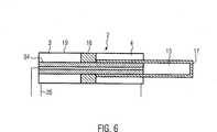
An die zweite Stellorganleitung
Abweichend zu den bisher beschriebenen Ausführungsformen ist die Arbeitsschaltung
Soll der Speicher gefüllt werden, wird der Kolben
Während des Füllvorgangs wird Fluid aus dem Reservoir
Im Betriebszustand kann der Kolben
Im Störungszustand wird das Schaltventil
In
Die Varianten des Betätigungssystems können in einem Verfahren zur Betätigung eines Stellorgans zum Einsatz kommen. Dabei wird während des gewöhnlichen Betriebszustands das Stellorgan mittels der Arbeitsschaltung betätigt. Sobald ein Störungszustand eintritt, wird das Stellorgan in die Sicherheitsstellung gebracht. Dies umfasst die Schritte: Verbinden des Speichers mit der ersten Kammer des Stellorgans, wobei ein von der Arbeitsschaltung vollständig entkoppelter Zufluss in die erste Kammer geschaffen ist, und Ablassen von Fluid in der zweiten Kammer des Stellorgans mittels des Ablassventils, das hierzu in Durchflussstellung gebracht werden kann.The variants of the actuation system can be used in a method for actuating an actuator. In this case, the actuator is actuated by means of the working circuit during the ordinary operating condition. As soon as a fault condition occurs, the actuator is brought into the safety position. This comprises the steps of: connecting the memory to the first chamber of the actuator, wherein a fully decoupled from the working circuit inlet is provided in the first chamber, and discharging fluid in the second chamber of the actuator by means of the drain valve, which are brought to flow position for this purpose can.
Bevorzugt wird das beschriebene Betätigungssystem und seine Varianten in einem der in der Einleitung genannten Anwendungsfällle angewendet. D. h., die beschriebenen Ausführungsformen des Betätigungssystems eigenen sich beispielsweise für Windkraftanlagen zur Einstellung des Anströmwinkels mindestens eines Rotorblattes, für Gas-, Dampf- oder Wasserturbinen zur Einstellung der jeweiligen Blattwinkel oder für Anwendungen der Öl- und Gasindustrie, in der Stellorgane genutzt werden, die im Störungszustand in eine Sicherheitsstellung überführt werden müssen.The described actuation system and its variants are preferably used in one of the application cases mentioned in the introduction. D. h., The described embodiments of the actuation system are suitable for example for wind turbines for adjusting the angle of attack of at least one rotor blade, for gas, steam or water turbines to adjust the respective blade angle or for applications of the oil and gas industry, are used in the actuators which must be transferred to a safety position in the event of a fault.
Insbesondere bei Windkraftanlagen ist es notwendig, die einzelnen Rotorblätter hinsichtlich ihres Anstellwinkels zum Wind verändern zu können. Bei Stürmen kann die maximale Belastbarkeit der Rotorblätter sowie der Gesamtstruktur erreicht werden. Es ist deshalb in diesen Fällen notwendig, die Rotorblätter in eine Sicherheitsstellung zu bringen, in denen diese dem Wind eine möglichst geringe Angriffsfläche bieten. Zudem besteht die Möglichkeit, dass die einzelnen Rotorblätter derart eingestellt werden, dass diese jeweils Drehmomente erzeugen, die sich gegenseitig aufheben und dadurch die Windkraftanlage im Stillstandstand halten. Dabei muss sichergestellt sein, dass diese Sicherheltsstellung(en) absolut zuverlässig erreicht werden. Es muss deshalb auch für den Fall eines Stromausfalls möglich sein, die Sicherheitsstellung vollständig automatisch einzunehmen.Especially with wind turbines, it is necessary to be able to change the individual rotor blades with respect to their angle of attack to the wind. In storms, the maximum load capacity of the rotor blades and the overall structure can be achieved. It is therefore necessary in these cases to bring the rotor blades in a safety position in which they offer the wind as small as possible attack surface. In addition, there is the possibility that the individual rotor blades are adjusted such that they each generate torques that cancel each other and thereby keep the wind turbine at a standstill. It must be ensured that this safety position (s) are achieved absolutely reliably. It must therefore be possible, even in the event of a power failure, to assume the safety position completely automatically.
Ähnliche Überlegungen treffen auch für den Einsatz des Betätigungssystems in Gasturbinen zum Verstellen des Gasmassestroms oder in Dampfturbinen zum Verstellen des Dampfmassestroms zu. Auch in solchen Systemen kann es notwendig werden ein Stellorgan zuverlässig in eine Sicherheitsstellung zu bringen. Das erfindungsgemäße Betätigungssystem sowie das Verfahren zur Betätigung eines Stellorgans ist deshalb hierfür ebenfalls einsetzbar. Similar considerations also apply to the use of the actuation system in gas turbines for adjusting the gas mass flow or in steam turbines for adjusting the steam mass flow. Even in such systems, it may be necessary to reliably bring an actuator into a safety position. The actuating system according to the invention and the method for actuating an actuator can therefore also be used for this purpose.
Das vorgestellte Betätigungssystem hat den Vorteil, dass die Sicherheitsstellung im Störungsfall lediglich mittels der im Speicher gespeicherten Energie erreicht wird. Selbst bei blockierter Pumpe oder zerstörten Leitungen in der Arbeitsschaltung kann das Stellorgan in die sichere Stellung gebracht werden. Das beschriebene Betätigungssystem in all seinen Ausführungsformen kann in einem sehr kleinen Bauraum verwirklicht werden. Es bietet sich deshalb an, bei Einsatz in Windkraftanlagen das Betätigungssystem vollständig im Rotor unterzubringen. Aufwändige und kostspielige Hydraulikdurchführungen vom rotierenden Rotor in das Maschinenhaus sind dadurch unnötig. Lediglich die notwendige Stromversorgung muss sichergestellt sein, was jedoch auf einfache Weise erreichbar ist.The presented actuating system has the advantage that the safety position in the event of a malfunction is achieved only by means of the energy stored in the memory. Even with a blocked pump or damaged lines in the work circuit, the actuator can be brought into the safe position. The described actuating system in all its embodiments can be realized in a very small space. It is therefore advisable, when used in wind turbines, to completely accommodate the actuating system in the rotor. Elaborate and expensive hydraulic feedthroughs from the rotating rotor to the machine house are therefore unnecessary. Only the necessary power supply must be ensured, but this is easily achievable.
Des Weiteren bieten die Varianten mit Ventilelementen
Das Konzept eines fluidtechnischen Systems, welches mindestens ein Stellorgan, eine Pumpe und einen Speicher umfasst, wobei das Stellorgan in einer Position festsetzbar ist während die Pumpe den Speicher lädt, wird als eigenständiges erfinderisches Konzept betrachtet. Dieses Konzept kann deshalb unabhängig von dem beschriebenen störungssicheren Betätigungssystem genutzt werden. Insbesondere ist es möglich einzelne Elemente oder Eigenschaften des störungssicheren Betätigungssystems beliebig mit einem fluidtechnischen System zum Festsetzen eines Stellorgans und Laden eines Speichers zu kombinieren.The concept of a fluid power system comprising at least one actuator, a pump and a reservoir, wherein the actuator is fixable in a position while the pump is loading the memory, is considered as an independent inventive concept. This concept can therefore be used independently of the described fail-safe actuation system. In particular, it is possible to arbitrarily combine individual elements or properties of the fail-safe actuating system with a fluidic system for setting an actuator and loading a memory.
Das gesamte störungssichere Betätigungssystem kann mittels elektronischer Komponenten überwacht werden. Dabei kann ein Eintreten eines Störungszustands in der Arbeitsschaltung bereits vor vollständigem Ausfall der Arbeitsschaltung erkannt werden. Daraufhin kann die Sicherheitsschaltung aktiviert werden, um einen weiteren Schaden an der Arbeitsschaltung zu verhindern. Es kann jedoch auch vorgesehen sein, dass das Einnehmen der Sicherheitsstellung mittels eines externen Signals, z. B. per Fernwartung, ausgelöst wird.The entire fail-safe actuation system can be monitored by means of electronic components. In this case, an occurrence of a fault condition in the work circuit can be detected even before complete failure of the work circuit. Then the safety circuit can be activated to prevent further damage to the working circuit. However, it can also be provided that the assumption of the safety position by means of an external signal, for. B. by remote maintenance, is triggered.
Besonders bevorzugt ist das Betätigungssystem ein selbstüberwachtes System, welches den Zustand des (Hochdruck-)Speichers, des Reservoirs (Niederdruckspeicher) sowie der Motor-/Pumpenvorrichtung und des im System befindlichen Fluidvolumens über eine Sensorik prüft und überwacht. Hierdurch wird es möglich Warnungen auszugeben bzw. ein „Condition Monitoring” durchzuführen und im Störungszustand selbsttätig ein einnehmen der sicheren Stellung einzuleiten.The actuation system is particularly preferably a self-monitored system which checks and monitors the state of the (high-pressure) accumulator, the reservoir (low-pressure accumulator) and the motor / pump device and the fluid volume in the system via a sensor system. This makes it possible to issue warnings or to perform a "condition monitoring" and automatically initiate an occupy the safe position in the fault state.
Die im Betätigungssystem eingesetzte Menge an Fluid beträgt üblicherweise weniger als 50 Liter, bevorzugt weniger als 20 Liter, besonders bevorzugt weniger als 12 Liter.The amount of fluid used in the actuation system is usually less than 50 liters, preferably less than 20 liters, more preferably less than 12 liters.
Das Betätigungssystem ist bevorzugt als geschlossenes System oder als geschlossener Kreislauf ausgebildet. Das Betätigungssystem kann als kompakte Einheit beispielsweise in der Nabe einer Windkraftanlage positioniert werden.The actuation system is preferably designed as a closed system or as a closed circuit. The actuation system can be positioned as a compact unit, for example in the hub of a wind turbine.
ZITATE ENTHALTEN IN DER BESCHREIBUNG QUOTES INCLUDE IN THE DESCRIPTION
Diese Liste der vom Anmelder aufgeführten Dokumente wurde automatisiert erzeugt und ist ausschließlich zur besseren Information des Lesers aufgenommen. Die Liste ist nicht Bestandteil der deutschen Patent- bzw. Gebrauchsmusteranmeldung. Das DPMA übernimmt keinerlei Haftung für etwaige Fehler oder Auslassungen.This list of the documents listed by the applicant has been generated automatically and is included solely for the better information of the reader. The list is not part of the German patent or utility model application. The DPMA assumes no liability for any errors or omissions.
Zitierte PatentliteraturCited patent literature
- WO 2009/064264 A1[0004]WO 2009/064264 A1[0004]
Claims (15)
Translated fromGermanPriority Applications (12)
| Application Number | Priority Date | Filing Date | Title |
|---|---|---|---|
| DE201010053811DE102010053811A1 (en) | 2010-12-08 | 2010-12-08 | Fault-proof actuation system |
| US13/992,441US9239064B2 (en) | 2010-12-08 | 2011-12-08 | Fail-safe actuation system |
| ES11794055.1TES2535243T3 (en) | 2010-12-08 | 2011-12-08 | Failsafe Drive System |
| PCT/EP2011/006187WO2012076178A1 (en) | 2010-12-08 | 2011-12-08 | Fail-safe actuation system |
| EP20110794055EP2649327B1 (en) | 2010-12-08 | 2011-12-08 | Fail-safe actuation system |
| BR112013014273ABR112013014273A2 (en) | 2010-12-08 | 2011-12-08 | fail-safe drive system |
| CN201410635886.7ACN104481934B (en) | 2010-12-08 | 2011-12-08 | Fail-safe actuation system |
| CN201180059437.7ACN103339390B (en) | 2010-12-08 | 2011-12-08 | Fail-safe actuation system |
| EP14187727.4AEP2840264B1 (en) | 2010-12-08 | 2011-12-08 | Fail-safe actuation system |
| DK11794055.1TDK2649327T3 (en) | 2010-12-08 | 2011-12-08 | FAULT-PROTECTED ACTIVATION SYSTEM |
| US14/619,773US9850916B2 (en) | 2010-12-08 | 2015-02-11 | Fail-safe actuation system |
| HK15106045.5AHK1205546A1 (en) | 2010-12-08 | 2015-06-25 | Fail-safe actuation system |
Applications Claiming Priority (1)
| Application Number | Priority Date | Filing Date | Title |
|---|---|---|---|
| DE201010053811DE102010053811A1 (en) | 2010-12-08 | 2010-12-08 | Fault-proof actuation system |
Publications (1)
| Publication Number | Publication Date |
|---|---|
| DE102010053811A1true DE102010053811A1 (en) | 2012-06-14 |
Family
ID=45315731
Family Applications (1)
| Application Number | Title | Priority Date | Filing Date |
|---|---|---|---|
| DE201010053811CeasedDE102010053811A1 (en) | 2010-12-08 | 2010-12-08 | Fault-proof actuation system |
Country Status (9)
| Country | Link |
|---|---|
| US (2) | US9239064B2 (en) |
| EP (2) | EP2649327B1 (en) |
| CN (2) | CN103339390B (en) |
| BR (1) | BR112013014273A2 (en) |
| DE (1) | DE102010053811A1 (en) |
| DK (1) | DK2649327T3 (en) |
| ES (1) | ES2535243T3 (en) |
| HK (1) | HK1205546A1 (en) |
| WO (1) | WO2012076178A1 (en) |
Cited By (8)
| Publication number | Priority date | Publication date | Assignee | Title |
|---|---|---|---|---|
| WO2014079528A1 (en)* | 2012-11-22 | 2014-05-30 | Hydac System Gmbh | Turbine valve actuator |
| NL2013841A (en)* | 2013-11-28 | 2015-06-01 | Bosch Gmbh Robert | Hydraulische hefeenheid voor een simulator en een simulator met een dergelijke hefeenheid. |
| EP3109485A1 (en)* | 2015-06-25 | 2016-12-28 | Robert Bosch Gmbh | Hydraulic system for pressure supply of a hydro-cylinder with three separate pressurisable surfaces and method for operating the hydraulic system |
| WO2018028944A1 (en)* | 2016-08-12 | 2018-02-15 | Robert Bosch Gmbh | Electrohydraulic adjustment drive, method for operating such an adjustment drive, and rotor |
| DE102016117358A1 (en) | 2016-09-15 | 2018-03-15 | Klemens Milde | Electro-pneumatic actuator |
| WO2018177640A1 (en)* | 2017-03-29 | 2018-10-04 | Voith Patent Gmbh | Apparatus for controlling a hydraulic machine |
| WO2018177641A1 (en)* | 2017-03-29 | 2018-10-04 | Voith Patent Gmbh | Apparatus for controlling a hydraulic machine |
| WO2023214880A1 (en)* | 2022-05-03 | 2023-11-09 | Speo Products As | Actuator assembly and method of use |
Families Citing this family (437)
| Publication number | Priority date | Publication date | Assignee | Title |
|---|---|---|---|---|
| US20070084897A1 (en) | 2003-05-20 | 2007-04-19 | Shelton Frederick E Iv | Articulating surgical stapling instrument incorporating a two-piece e-beam firing mechanism |
| US9060770B2 (en) | 2003-05-20 | 2015-06-23 | Ethicon Endo-Surgery, Inc. | Robotically-driven surgical instrument with E-beam driver |
| US11890012B2 (en) | 2004-07-28 | 2024-02-06 | Cilag Gmbh International | Staple cartridge comprising cartridge body and attached support |
| US9072535B2 (en) | 2011-05-27 | 2015-07-07 | Ethicon Endo-Surgery, Inc. | Surgical stapling instruments with rotatable staple deployment arrangements |
| US11998198B2 (en) | 2004-07-28 | 2024-06-04 | Cilag Gmbh International | Surgical stapling instrument incorporating a two-piece E-beam firing mechanism |
| US8215531B2 (en) | 2004-07-28 | 2012-07-10 | Ethicon Endo-Surgery, Inc. | Surgical stapling instrument having a medical substance dispenser |
| US11246590B2 (en) | 2005-08-31 | 2022-02-15 | Cilag Gmbh International | Staple cartridge including staple drivers having different unfired heights |
| US10159482B2 (en) | 2005-08-31 | 2018-12-25 | Ethicon Llc | Fastener cartridge assembly comprising a fixed anvil and different staple heights |
| US7669746B2 (en) | 2005-08-31 | 2010-03-02 | Ethicon Endo-Surgery, Inc. | Staple cartridges for forming staples having differing formed staple heights |
| US9237891B2 (en) | 2005-08-31 | 2016-01-19 | Ethicon Endo-Surgery, Inc. | Robotically-controlled surgical stapling devices that produce formed staples having different lengths |
| US11484312B2 (en) | 2005-08-31 | 2022-11-01 | Cilag Gmbh International | Staple cartridge comprising a staple driver arrangement |
| US7934630B2 (en) | 2005-08-31 | 2011-05-03 | Ethicon Endo-Surgery, Inc. | Staple cartridges for forming staples having differing formed staple heights |
| US20070106317A1 (en) | 2005-11-09 | 2007-05-10 | Shelton Frederick E Iv | Hydraulically and electrically actuated articulation joints for surgical instruments |
| US20110024477A1 (en) | 2009-02-06 | 2011-02-03 | Hall Steven G | Driven Surgical Stapler Improvements |
| US8820603B2 (en) | 2006-01-31 | 2014-09-02 | Ethicon Endo-Surgery, Inc. | Accessing data stored in a memory of a surgical instrument |
| US20120292367A1 (en) | 2006-01-31 | 2012-11-22 | Ethicon Endo-Surgery, Inc. | Robotically-controlled end effector |
| US7845537B2 (en) | 2006-01-31 | 2010-12-07 | Ethicon Endo-Surgery, Inc. | Surgical instrument having recording capabilities |
| US11793518B2 (en) | 2006-01-31 | 2023-10-24 | Cilag Gmbh International | Powered surgical instruments with firing system lockout arrangements |
| US11224427B2 (en) | 2006-01-31 | 2022-01-18 | Cilag Gmbh International | Surgical stapling system including a console and retraction assembly |
| US8186555B2 (en) | 2006-01-31 | 2012-05-29 | Ethicon Endo-Surgery, Inc. | Motor-driven surgical cutting and fastening instrument with mechanical closure system |
| US11278279B2 (en) | 2006-01-31 | 2022-03-22 | Cilag Gmbh International | Surgical instrument assembly |
| US8708213B2 (en) | 2006-01-31 | 2014-04-29 | Ethicon Endo-Surgery, Inc. | Surgical instrument having a feedback system |
| US20110295295A1 (en) | 2006-01-31 | 2011-12-01 | Ethicon Endo-Surgery, Inc. | Robotically-controlled surgical instrument having recording capabilities |
| US7753904B2 (en) | 2006-01-31 | 2010-07-13 | Ethicon Endo-Surgery, Inc. | Endoscopic surgical instrument with a handle that can articulate with respect to the shaft |
| US8992422B2 (en) | 2006-03-23 | 2015-03-31 | Ethicon Endo-Surgery, Inc. | Robotically-controlled endoscopic accessory channel |
| US8322455B2 (en) | 2006-06-27 | 2012-12-04 | Ethicon Endo-Surgery, Inc. | Manually driven surgical cutting and fastening instrument |
| US10568652B2 (en) | 2006-09-29 | 2020-02-25 | Ethicon Llc | Surgical staples having attached drivers of different heights and stapling instruments for deploying the same |
| US7506791B2 (en) | 2006-09-29 | 2009-03-24 | Ethicon Endo-Surgery, Inc. | Surgical stapling instrument with mechanical mechanism for limiting maximum tissue compression |
| US11980366B2 (en) | 2006-10-03 | 2024-05-14 | Cilag Gmbh International | Surgical instrument |
| US8684253B2 (en) | 2007-01-10 | 2014-04-01 | Ethicon Endo-Surgery, Inc. | Surgical instrument with wireless communication between a control unit of a robotic system and remote sensor |
| US8652120B2 (en) | 2007-01-10 | 2014-02-18 | Ethicon Endo-Surgery, Inc. | Surgical instrument with wireless communication between control unit and sensor transponders |
| US11291441B2 (en) | 2007-01-10 | 2022-04-05 | Cilag Gmbh International | Surgical instrument with wireless communication between control unit and remote sensor |
| US8632535B2 (en) | 2007-01-10 | 2014-01-21 | Ethicon Endo-Surgery, Inc. | Interlock and surgical instrument including same |
| US20080169333A1 (en) | 2007-01-11 | 2008-07-17 | Shelton Frederick E | Surgical stapler end effector with tapered distal end |
| US11039836B2 (en) | 2007-01-11 | 2021-06-22 | Cilag Gmbh International | Staple cartridge for use with a surgical stapling instrument |
| US7673782B2 (en) | 2007-03-15 | 2010-03-09 | Ethicon Endo-Surgery, Inc. | Surgical stapling instrument having a releasable buttress material |
| US8893946B2 (en) | 2007-03-28 | 2014-11-25 | Ethicon Endo-Surgery, Inc. | Laparoscopic tissue thickness and clamp load measuring devices |
| US8931682B2 (en) | 2007-06-04 | 2015-01-13 | Ethicon Endo-Surgery, Inc. | Robotically-controlled shaft based rotary drive systems for surgical instruments |
| US11564682B2 (en) | 2007-06-04 | 2023-01-31 | Cilag Gmbh International | Surgical stapler device |
| US7753245B2 (en) | 2007-06-22 | 2010-07-13 | Ethicon Endo-Surgery, Inc. | Surgical stapling instruments |
| US11849941B2 (en) | 2007-06-29 | 2023-12-26 | Cilag Gmbh International | Staple cartridge having staple cavities extending at a transverse angle relative to a longitudinal cartridge axis |
| JP5410110B2 (en) | 2008-02-14 | 2014-02-05 | エシコン・エンド−サージェリィ・インコーポレイテッド | Surgical cutting / fixing instrument with RF electrode |
| US8573465B2 (en) | 2008-02-14 | 2013-11-05 | Ethicon Endo-Surgery, Inc. | Robotically-controlled surgical end effector system with rotary actuated closure systems |
| US11986183B2 (en) | 2008-02-14 | 2024-05-21 | Cilag Gmbh International | Surgical cutting and fastening instrument comprising a plurality of sensors to measure an electrical parameter |
| US8636736B2 (en) | 2008-02-14 | 2014-01-28 | Ethicon Endo-Surgery, Inc. | Motorized surgical cutting and fastening instrument |
| US8758391B2 (en) | 2008-02-14 | 2014-06-24 | Ethicon Endo-Surgery, Inc. | Interchangeable tools for surgical instruments |
| US9179912B2 (en) | 2008-02-14 | 2015-11-10 | Ethicon Endo-Surgery, Inc. | Robotically-controlled motorized surgical cutting and fastening instrument |
| US7866527B2 (en) | 2008-02-14 | 2011-01-11 | Ethicon Endo-Surgery, Inc. | Surgical stapling apparatus with interlockable firing system |
| US7819298B2 (en) | 2008-02-14 | 2010-10-26 | Ethicon Endo-Surgery, Inc. | Surgical stapling apparatus with control features operable with one hand |
| US9585657B2 (en) | 2008-02-15 | 2017-03-07 | Ethicon Endo-Surgery, Llc | Actuator for releasing a layer of material from a surgical end effector |
| US9386983B2 (en) | 2008-09-23 | 2016-07-12 | Ethicon Endo-Surgery, Llc | Robotically-controlled motorized surgical instrument |
| US8210411B2 (en) | 2008-09-23 | 2012-07-03 | Ethicon Endo-Surgery, Inc. | Motor-driven surgical cutting instrument |
| US9005230B2 (en) | 2008-09-23 | 2015-04-14 | Ethicon Endo-Surgery, Inc. | Motorized surgical instrument |
| US11648005B2 (en) | 2008-09-23 | 2023-05-16 | Cilag Gmbh International | Robotically-controlled motorized surgical instrument with an end effector |
| US8608045B2 (en) | 2008-10-10 | 2013-12-17 | Ethicon Endo-Sugery, Inc. | Powered surgical cutting and stapling apparatus with manually retractable firing system |
| US8517239B2 (en) | 2009-02-05 | 2013-08-27 | Ethicon Endo-Surgery, Inc. | Surgical stapling instrument comprising a magnetic element driver |
| US8444036B2 (en) | 2009-02-06 | 2013-05-21 | Ethicon Endo-Surgery, Inc. | Motor driven surgical fastener device with mechanisms for adjusting a tissue gap within the end effector |
| RU2525225C2 (en) | 2009-02-06 | 2014-08-10 | Этикон Эндо-Серджери, Инк. | Improvement of drive surgical suturing instrument |
| US8220688B2 (en) | 2009-12-24 | 2012-07-17 | Ethicon Endo-Surgery, Inc. | Motor-driven surgical cutting instrument with electric actuator directional control assembly |
| US8851354B2 (en) | 2009-12-24 | 2014-10-07 | Ethicon Endo-Surgery, Inc. | Surgical cutting instrument that analyzes tissue thickness |
| US8783543B2 (en) | 2010-07-30 | 2014-07-22 | Ethicon Endo-Surgery, Inc. | Tissue acquisition arrangements and methods for surgical stapling devices |
| US12213666B2 (en) | 2010-09-30 | 2025-02-04 | Cilag Gmbh International | Tissue thickness compensator comprising layers |
| US11812965B2 (en) | 2010-09-30 | 2023-11-14 | Cilag Gmbh International | Layer of material for a surgical end effector |
| US11925354B2 (en) | 2010-09-30 | 2024-03-12 | Cilag Gmbh International | Staple cartridge comprising staples positioned within a compressible portion thereof |
| US9364233B2 (en) | 2010-09-30 | 2016-06-14 | Ethicon Endo-Surgery, Llc | Tissue thickness compensators for circular surgical staplers |
| US9351730B2 (en) | 2011-04-29 | 2016-05-31 | Ethicon Endo-Surgery, Llc | Tissue thickness compensator comprising channels |
| US10945731B2 (en) | 2010-09-30 | 2021-03-16 | Ethicon Llc | Tissue thickness compensator comprising controlled release and expansion |
| US9386988B2 (en) | 2010-09-30 | 2016-07-12 | Ethicon End-Surgery, LLC | Retainer assembly including a tissue thickness compensator |
| US9788834B2 (en) | 2010-09-30 | 2017-10-17 | Ethicon Llc | Layer comprising deployable attachment members |
| US9016542B2 (en) | 2010-09-30 | 2015-04-28 | Ethicon Endo-Surgery, Inc. | Staple cartridge comprising compressible distortion resistant components |
| US11298125B2 (en) | 2010-09-30 | 2022-04-12 | Cilag Gmbh International | Tissue stapler having a thickness compensator |
| US9629814B2 (en) | 2010-09-30 | 2017-04-25 | Ethicon Endo-Surgery, Llc | Tissue thickness compensator configured to redistribute compressive forces |
| US8695866B2 (en) | 2010-10-01 | 2014-04-15 | Ethicon Endo-Surgery, Inc. | Surgical instrument having a power control circuit |
| AU2012250197B2 (en) | 2011-04-29 | 2017-08-10 | Ethicon Endo-Surgery, Inc. | Staple cartridge comprising staples positioned within a compressible portion thereof |
| US11207064B2 (en) | 2011-05-27 | 2021-12-28 | Cilag Gmbh International | Automated end effector component reloading system for use with a robotic system |
| US9044230B2 (en) | 2012-02-13 | 2015-06-02 | Ethicon Endo-Surgery, Inc. | Surgical cutting and fastening instrument with apparatus for determining cartridge and firing motion status |
| BR112014024098B1 (en) | 2012-03-28 | 2021-05-25 | Ethicon Endo-Surgery, Inc. | staple cartridge |
| MX358135B (en) | 2012-03-28 | 2018-08-06 | Ethicon Endo Surgery Inc | Tissue thickness compensator comprising a plurality of layers. |
| JP6224070B2 (en) | 2012-03-28 | 2017-11-01 | エシコン・エンド−サージェリィ・インコーポレイテッドEthicon Endo−Surgery,Inc. | Retainer assembly including tissue thickness compensator |
| WO2013176723A1 (en)* | 2012-05-22 | 2013-11-28 | United Technologies Corporation | Wind turbine load mitigation |
| US9101358B2 (en) | 2012-06-15 | 2015-08-11 | Ethicon Endo-Surgery, Inc. | Articulatable surgical instrument comprising a firing drive |
| DE102012012142A1 (en)* | 2012-06-20 | 2013-12-24 | Robert Bosch Gmbh | Hydraulic actuating device |
| US12383267B2 (en) | 2012-06-28 | 2025-08-12 | Cilag Gmbh International | Robotically powered surgical device with manually-actuatable reversing system |
| US9289256B2 (en) | 2012-06-28 | 2016-03-22 | Ethicon Endo-Surgery, Llc | Surgical end effectors having angled tissue-contacting surfaces |
| BR112014032776B1 (en) | 2012-06-28 | 2021-09-08 | Ethicon Endo-Surgery, Inc | SURGICAL INSTRUMENT SYSTEM AND SURGICAL KIT FOR USE WITH A SURGICAL INSTRUMENT SYSTEM |
| US9282974B2 (en) | 2012-06-28 | 2016-03-15 | Ethicon Endo-Surgery, Llc | Empty clip cartridge lockout |
| US11278284B2 (en) | 2012-06-28 | 2022-03-22 | Cilag Gmbh International | Rotary drive arrangements for surgical instruments |
| US20140001231A1 (en) | 2012-06-28 | 2014-01-02 | Ethicon Endo-Surgery, Inc. | Firing system lockout arrangements for surgical instruments |
| US9408606B2 (en) | 2012-06-28 | 2016-08-09 | Ethicon Endo-Surgery, Llc | Robotically powered surgical device with manually-actuatable reversing system |
| US20140005718A1 (en) | 2012-06-28 | 2014-01-02 | Ethicon Endo-Surgery, Inc. | Multi-functional powered surgical device with external dissection features |
| JP6290201B2 (en) | 2012-06-28 | 2018-03-07 | エシコン・エンド−サージェリィ・インコーポレイテッドEthicon Endo−Surgery,Inc. | Lockout for empty clip cartridge |
| DE102012022030A1 (en)* | 2012-11-12 | 2014-05-15 | Deere & Company | Suspension device for a movably mounted vehicle axle |
| RU2672520C2 (en) | 2013-03-01 | 2018-11-15 | Этикон Эндо-Серджери, Инк. | Hingedly turnable surgical instruments with conducting ways for signal transfer |
| BR112015021082B1 (en) | 2013-03-01 | 2022-05-10 | Ethicon Endo-Surgery, Inc | surgical instrument |
| US9808244B2 (en) | 2013-03-14 | 2017-11-07 | Ethicon Llc | Sensor arrangements for absolute positioning system for surgical instruments |
| US9629629B2 (en) | 2013-03-14 | 2017-04-25 | Ethicon Endo-Surgey, LLC | Control systems for surgical instruments |
| US9826976B2 (en) | 2013-04-16 | 2017-11-28 | Ethicon Llc | Motor driven surgical instruments with lockable dual drive shafts |
| BR112015026109B1 (en) | 2013-04-16 | 2022-02-22 | Ethicon Endo-Surgery, Inc | surgical instrument |
| DE102013008047A1 (en)* | 2013-05-13 | 2014-11-13 | Robert Bosch Gmbh | Variable speed drive with two pumps and one differential cylinder |
| NO336260B1 (en)* | 2013-06-11 | 2015-07-06 | Mørenot Offshore As | Apparatus for controlling a deflector and an actuator for use in the apparatus |
| MX369362B (en) | 2013-08-23 | 2019-11-06 | Ethicon Endo Surgery Llc | Firing member retraction devices for powered surgical instruments. |
| US9775609B2 (en) | 2013-08-23 | 2017-10-03 | Ethicon Llc | Tamper proof circuit for surgical instrument battery pack |
| US9962161B2 (en) | 2014-02-12 | 2018-05-08 | Ethicon Llc | Deliverable surgical instrument |
| US10013049B2 (en) | 2014-03-26 | 2018-07-03 | Ethicon Llc | Power management through sleep options of segmented circuit and wake up control |
| BR112016021943B1 (en) | 2014-03-26 | 2022-06-14 | Ethicon Endo-Surgery, Llc | SURGICAL INSTRUMENT FOR USE BY AN OPERATOR IN A SURGICAL PROCEDURE |
| US10004497B2 (en) | 2014-03-26 | 2018-06-26 | Ethicon Llc | Interface systems for use with surgical instruments |
| US20150272580A1 (en) | 2014-03-26 | 2015-10-01 | Ethicon Endo-Surgery, Inc. | Verification of number of battery exchanges/procedure count |
| US12232723B2 (en) | 2014-03-26 | 2025-02-25 | Cilag Gmbh International | Systems and methods for controlling a segmented circuit |
| US10470768B2 (en) | 2014-04-16 | 2019-11-12 | Ethicon Llc | Fastener cartridge including a layer attached thereto |
| CN106456159B (en) | 2014-04-16 | 2019-03-08 | 伊西康内外科有限责任公司 | Fastener Cartridge Assembly and Nail Retainer Cover Arrangement |
| CN106456176B (en) | 2014-04-16 | 2019-06-28 | 伊西康内外科有限责任公司 | Fastener Cartridge Including Extensions With Different Configurations |
| US10327764B2 (en) | 2014-09-26 | 2019-06-25 | Ethicon Llc | Method for creating a flexible staple line |
| US20150297225A1 (en) | 2014-04-16 | 2015-10-22 | Ethicon Endo-Surgery, Inc. | Fastener cartridges including extensions having different configurations |
| BR112016023825B1 (en) | 2014-04-16 | 2022-08-02 | Ethicon Endo-Surgery, Llc | STAPLE CARTRIDGE FOR USE WITH A SURGICAL STAPLER AND STAPLE CARTRIDGE FOR USE WITH A SURGICAL INSTRUMENT |
| EP2952750B1 (en)* | 2014-06-04 | 2018-09-05 | MOOG GmbH | Hydraulic system |
| DE102014012694B3 (en)* | 2014-09-01 | 2016-02-25 | Böhner-EH GmbH | Hydraulic device |
| US11311294B2 (en) | 2014-09-05 | 2022-04-26 | Cilag Gmbh International | Powered medical device including measurement of closure state of jaws |
| US10135242B2 (en) | 2014-09-05 | 2018-11-20 | Ethicon Llc | Smart cartridge wake up operation and data retention |
| BR112017004361B1 (en) | 2014-09-05 | 2023-04-11 | Ethicon Llc | ELECTRONIC SYSTEM FOR A SURGICAL INSTRUMENT |
| US10105142B2 (en) | 2014-09-18 | 2018-10-23 | Ethicon Llc | Surgical stapler with plurality of cutting elements |
| DE102014218886B3 (en)* | 2014-09-19 | 2015-11-12 | Voith Patent Gmbh | Hydraulic drive with fast lift and load stroke |
| CN107427300B (en) | 2014-09-26 | 2020-12-04 | 伊西康有限责任公司 | Surgical suture buttresses and auxiliary materials |
| US11523821B2 (en) | 2014-09-26 | 2022-12-13 | Cilag Gmbh International | Method for creating a flexible staple line |
| US10076325B2 (en) | 2014-10-13 | 2018-09-18 | Ethicon Llc | Surgical stapling apparatus comprising a tissue stop |
| US9924944B2 (en) | 2014-10-16 | 2018-03-27 | Ethicon Llc | Staple cartridge comprising an adjunct material |
| US11141153B2 (en) | 2014-10-29 | 2021-10-12 | Cilag Gmbh International | Staple cartridges comprising driver arrangements |
| US10517594B2 (en) | 2014-10-29 | 2019-12-31 | Ethicon Llc | Cartridge assemblies for surgical staplers |
| US9844376B2 (en) | 2014-11-06 | 2017-12-19 | Ethicon Llc | Staple cartridge comprising a releasable adjunct material |
| US10736636B2 (en) | 2014-12-10 | 2020-08-11 | Ethicon Llc | Articulatable surgical instrument system |
| US10085748B2 (en) | 2014-12-18 | 2018-10-02 | Ethicon Llc | Locking arrangements for detachable shaft assemblies with articulatable surgical end effectors |
| US9844375B2 (en) | 2014-12-18 | 2017-12-19 | Ethicon Llc | Drive arrangements for articulatable surgical instruments |
| MX389118B (en) | 2014-12-18 | 2025-03-20 | Ethicon Llc | SURGICAL INSTRUMENT WITH AN ANVIL THAT CAN BE SELECTIVELY MOVED ON A DISCRETE, NON-MOBILE AXIS RELATIVE TO A STAPLE CARTRIDGE. |
| US9943309B2 (en) | 2014-12-18 | 2018-04-17 | Ethicon Llc | Surgical instruments with articulatable end effectors and movable firing beam support arrangements |
| US9844374B2 (en) | 2014-12-18 | 2017-12-19 | Ethicon Llc | Surgical instrument systems comprising an articulatable end effector and means for adjusting the firing stroke of a firing member |
| US9987000B2 (en) | 2014-12-18 | 2018-06-05 | Ethicon Llc | Surgical instrument assembly comprising a flexible articulation system |
| US11154301B2 (en) | 2015-02-27 | 2021-10-26 | Cilag Gmbh International | Modular stapling assembly |
| ITUB20150172A1 (en)* | 2015-03-04 | 2016-09-04 | Mecc Breganzese S P A | HYDRAULIC EQUIPMENT FOR EXCAVATORS AND OPERATING MACHINES IN GENERAL |
| US10245033B2 (en) | 2015-03-06 | 2019-04-02 | Ethicon Llc | Surgical instrument comprising a lockable battery housing |
| JP2020121162A (en) | 2015-03-06 | 2020-08-13 | エシコン エルエルシーEthicon LLC | Time dependent evaluation of sensor data to determine stability element, creep element and viscoelastic element of measurement |
| US10441279B2 (en) | 2015-03-06 | 2019-10-15 | Ethicon Llc | Multiple level thresholds to modify operation of powered surgical instruments |
| US9993248B2 (en) | 2015-03-06 | 2018-06-12 | Ethicon Endo-Surgery, Llc | Smart sensors with local signal processing |
| US9901342B2 (en) | 2015-03-06 | 2018-02-27 | Ethicon Endo-Surgery, Llc | Signal and power communication system positioned on a rotatable shaft |
| US10687806B2 (en) | 2015-03-06 | 2020-06-23 | Ethicon Llc | Adaptive tissue compression techniques to adjust closure rates for multiple tissue types |
| US9924961B2 (en) | 2015-03-06 | 2018-03-27 | Ethicon Endo-Surgery, Llc | Interactive feedback system for powered surgical instruments |
| US10548504B2 (en) | 2015-03-06 | 2020-02-04 | Ethicon Llc | Overlaid multi sensor radio frequency (RF) electrode system to measure tissue compression |
| US9808246B2 (en) | 2015-03-06 | 2017-11-07 | Ethicon Endo-Surgery, Llc | Method of operating a powered surgical instrument |
| US10617412B2 (en) | 2015-03-06 | 2020-04-14 | Ethicon Llc | System for detecting the mis-insertion of a staple cartridge into a surgical stapler |
| US10433844B2 (en) | 2015-03-31 | 2019-10-08 | Ethicon Llc | Surgical instrument with selectively disengageable threaded drive systems |
| US10835249B2 (en) | 2015-08-17 | 2020-11-17 | Ethicon Llc | Implantable layers for a surgical instrument |
| US10105139B2 (en) | 2015-09-23 | 2018-10-23 | Ethicon Llc | Surgical stapler having downstream current-based motor control |
| US10238386B2 (en) | 2015-09-23 | 2019-03-26 | Ethicon Llc | Surgical stapler having motor control based on an electrical parameter related to a motor current |
| US10327769B2 (en) | 2015-09-23 | 2019-06-25 | Ethicon Llc | Surgical stapler having motor control based on a drive system component |
| US10299878B2 (en) | 2015-09-25 | 2019-05-28 | Ethicon Llc | Implantable adjunct systems for determining adjunct skew |
| US10433846B2 (en) | 2015-09-30 | 2019-10-08 | Ethicon Llc | Compressible adjunct with crossing spacer fibers |
| US10980539B2 (en) | 2015-09-30 | 2021-04-20 | Ethicon Llc | Implantable adjunct comprising bonded layers |
| US11890015B2 (en) | 2015-09-30 | 2024-02-06 | Cilag Gmbh International | Compressible adjunct with crossing spacer fibers |
| US10478188B2 (en) | 2015-09-30 | 2019-11-19 | Ethicon Llc | Implantable layer comprising a constricted configuration |
| US10265068B2 (en) | 2015-12-30 | 2019-04-23 | Ethicon Llc | Surgical instruments with separable motors and motor control circuits |
| US10292704B2 (en) | 2015-12-30 | 2019-05-21 | Ethicon Llc | Mechanisms for compensating for battery pack failure in powered surgical instruments |
| US10368865B2 (en) | 2015-12-30 | 2019-08-06 | Ethicon Llc | Mechanisms for compensating for drivetrain failure in powered surgical instruments |
| US11213293B2 (en) | 2016-02-09 | 2022-01-04 | Cilag Gmbh International | Articulatable surgical instruments with single articulation link arrangements |
| BR112018016098B1 (en) | 2016-02-09 | 2023-02-23 | Ethicon Llc | SURGICAL INSTRUMENT |
| US10413291B2 (en) | 2016-02-09 | 2019-09-17 | Ethicon Llc | Surgical instrument articulation mechanism with slotted secondary constraint |
| US11224426B2 (en) | 2016-02-12 | 2022-01-18 | Cilag Gmbh International | Mechanisms for compensating for drivetrain failure in powered surgical instruments |
| US10448948B2 (en) | 2016-02-12 | 2019-10-22 | Ethicon Llc | Mechanisms for compensating for drivetrain failure in powered surgical instruments |
| WO2017144875A1 (en)* | 2016-02-23 | 2017-08-31 | Quoceant Limited | Hydraulic fluid power transmission |
| US10413297B2 (en) | 2016-04-01 | 2019-09-17 | Ethicon Llc | Surgical stapling system configured to apply annular rows of staples having different heights |
| US10617413B2 (en) | 2016-04-01 | 2020-04-14 | Ethicon Llc | Closure system arrangements for surgical cutting and stapling devices with separate and distinct firing shafts |
| US10828028B2 (en) | 2016-04-15 | 2020-11-10 | Ethicon Llc | Surgical instrument with multiple program responses during a firing motion |
| US11607239B2 (en) | 2016-04-15 | 2023-03-21 | Cilag Gmbh International | Systems and methods for controlling a surgical stapling and cutting instrument |
| US11179150B2 (en) | 2016-04-15 | 2021-11-23 | Cilag Gmbh International | Systems and methods for controlling a surgical stapling and cutting instrument |
| US10492783B2 (en) | 2016-04-15 | 2019-12-03 | Ethicon, Llc | Surgical instrument with improved stop/start control during a firing motion |
| US10405859B2 (en) | 2016-04-15 | 2019-09-10 | Ethicon Llc | Surgical instrument with adjustable stop/start control during a firing motion |
| US10335145B2 (en) | 2016-04-15 | 2019-07-02 | Ethicon Llc | Modular surgical instrument with configurable operating mode |
| US10456137B2 (en) | 2016-04-15 | 2019-10-29 | Ethicon Llc | Staple formation detection mechanisms |
| US10426467B2 (en) | 2016-04-15 | 2019-10-01 | Ethicon Llc | Surgical instrument with detection sensors |
| US10357247B2 (en) | 2016-04-15 | 2019-07-23 | Ethicon Llc | Surgical instrument with multiple program responses during a firing motion |
| US20170296173A1 (en) | 2016-04-18 | 2017-10-19 | Ethicon Endo-Surgery, Llc | Method for operating a surgical instrument |
| US10363037B2 (en) | 2016-04-18 | 2019-07-30 | Ethicon Llc | Surgical instrument system comprising a magnetic lockout |
| US11317917B2 (en) | 2016-04-18 | 2022-05-03 | Cilag Gmbh International | Surgical stapling system comprising a lockable firing assembly |
| US10500000B2 (en) | 2016-08-16 | 2019-12-10 | Ethicon Llc | Surgical tool with manual control of end effector jaws |
| EP3333400B1 (en)* | 2016-12-12 | 2021-04-07 | Goodrich Actuation Systems Limited | Thrust reverser actuation system |
| CN110087565A (en) | 2016-12-21 | 2019-08-02 | 爱惜康有限责任公司 | Surgical stapling system |
| US10568625B2 (en) | 2016-12-21 | 2020-02-25 | Ethicon Llc | Staple cartridges and arrangements of staples and staple cavities therein |
| US11090048B2 (en) | 2016-12-21 | 2021-08-17 | Cilag Gmbh International | Method for resetting a fuse of a surgical instrument shaft |
| US10695055B2 (en) | 2016-12-21 | 2020-06-30 | Ethicon Llc | Firing assembly comprising a lockout |
| JP6983893B2 (en) | 2016-12-21 | 2021-12-17 | エシコン エルエルシーEthicon LLC | Lockout configuration for surgical end effectors and replaceable tool assemblies |
| US10980536B2 (en) | 2016-12-21 | 2021-04-20 | Ethicon Llc | No-cartridge and spent cartridge lockout arrangements for surgical staplers |
| US20180168615A1 (en) | 2016-12-21 | 2018-06-21 | Ethicon Endo-Surgery, Llc | Method of deforming staples from two different types of staple cartridges with the same surgical stapling instrument |
| US10426471B2 (en) | 2016-12-21 | 2019-10-01 | Ethicon Llc | Surgical instrument with multiple failure response modes |
| JP2020501815A (en) | 2016-12-21 | 2020-01-23 | エシコン エルエルシーEthicon LLC | Surgical stapling system |
| MX2019007295A (en) | 2016-12-21 | 2019-10-15 | Ethicon Llc | Surgical instrument system comprising an end effector lockout and a firing assembly lockout. |
| US11134942B2 (en) | 2016-12-21 | 2021-10-05 | Cilag Gmbh International | Surgical stapling instruments and staple-forming anvils |
| US10813638B2 (en) | 2016-12-21 | 2020-10-27 | Ethicon Llc | Surgical end effectors with expandable tissue stop arrangements |
| JP7010956B2 (en) | 2016-12-21 | 2022-01-26 | エシコン エルエルシー | How to staple tissue |
| US11419606B2 (en) | 2016-12-21 | 2022-08-23 | Cilag Gmbh International | Shaft assembly comprising a clutch configured to adapt the output of a rotary firing member to two different systems |
| US10582928B2 (en) | 2016-12-21 | 2020-03-10 | Ethicon Llc | Articulation lock arrangements for locking an end effector in an articulated position in response to actuation of a jaw closure system |
| JP7010957B2 (en) | 2016-12-21 | 2022-01-26 | エシコン エルエルシー | Shaft assembly with lockout |
| US10485543B2 (en) | 2016-12-21 | 2019-11-26 | Ethicon Llc | Anvil having a knife slot width |
| US10758229B2 (en) | 2016-12-21 | 2020-09-01 | Ethicon Llc | Surgical instrument comprising improved jaw control |
| US10898186B2 (en) | 2016-12-21 | 2021-01-26 | Ethicon Llc | Staple forming pocket arrangements comprising primary sidewalls and pocket sidewalls |
| US10542982B2 (en) | 2016-12-21 | 2020-01-28 | Ethicon Llc | Shaft assembly comprising first and second articulation lockouts |
| US20180168625A1 (en) | 2016-12-21 | 2018-06-21 | Ethicon Endo-Surgery, Llc | Surgical stapling instruments with smart staple cartridges |
| US10973516B2 (en) | 2016-12-21 | 2021-04-13 | Ethicon Llc | Surgical end effectors and adaptable firing members therefor |
| US10624633B2 (en) | 2017-06-20 | 2020-04-21 | Ethicon Llc | Systems and methods for controlling motor velocity of a surgical stapling and cutting instrument |
| US11517325B2 (en) | 2017-06-20 | 2022-12-06 | Cilag Gmbh International | Closed loop feedback control of motor velocity of a surgical stapling and cutting instrument based on measured displacement distance traveled over a specified time interval |
| US11071554B2 (en) | 2017-06-20 | 2021-07-27 | Cilag Gmbh International | Closed loop feedback control of motor velocity of a surgical stapling and cutting instrument based on magnitude of velocity error measurements |
| US10368864B2 (en) | 2017-06-20 | 2019-08-06 | Ethicon Llc | Systems and methods for controlling displaying motor velocity for a surgical instrument |
| USD879808S1 (en) | 2017-06-20 | 2020-03-31 | Ethicon Llc | Display panel with graphical user interface |
| USD879809S1 (en) | 2017-06-20 | 2020-03-31 | Ethicon Llc | Display panel with changeable graphical user interface |
| US11382638B2 (en) | 2017-06-20 | 2022-07-12 | Cilag Gmbh International | Closed loop feedback control of motor velocity of a surgical stapling and cutting instrument based on measured time over a specified displacement distance |
| US10813639B2 (en) | 2017-06-20 | 2020-10-27 | Ethicon Llc | Closed loop feedback control of motor velocity of a surgical stapling and cutting instrument based on system conditions |
| US10327767B2 (en) | 2017-06-20 | 2019-06-25 | Ethicon Llc | Control of motor velocity of a surgical stapling and cutting instrument based on angle of articulation |
| US10646220B2 (en) | 2017-06-20 | 2020-05-12 | Ethicon Llc | Systems and methods for controlling displacement member velocity for a surgical instrument |
| US10881399B2 (en) | 2017-06-20 | 2021-01-05 | Ethicon Llc | Techniques for adaptive control of motor velocity of a surgical stapling and cutting instrument |
| US10980537B2 (en) | 2017-06-20 | 2021-04-20 | Ethicon Llc | Closed loop feedback control of motor velocity of a surgical stapling and cutting instrument based on measured time over a specified number of shaft rotations |
| US10888321B2 (en) | 2017-06-20 | 2021-01-12 | Ethicon Llc | Systems and methods for controlling velocity of a displacement member of a surgical stapling and cutting instrument |
| US10779820B2 (en) | 2017-06-20 | 2020-09-22 | Ethicon Llc | Systems and methods for controlling motor speed according to user input for a surgical instrument |
| US10307170B2 (en) | 2017-06-20 | 2019-06-04 | Ethicon Llc | Method for closed loop control of motor velocity of a surgical stapling and cutting instrument |
| US11653914B2 (en) | 2017-06-20 | 2023-05-23 | Cilag Gmbh International | Systems and methods for controlling motor velocity of a surgical stapling and cutting instrument according to articulation angle of end effector |
| USD890784S1 (en) | 2017-06-20 | 2020-07-21 | Ethicon Llc | Display panel with changeable graphical user interface |
| US11090046B2 (en) | 2017-06-20 | 2021-08-17 | Cilag Gmbh International | Systems and methods for controlling displacement member motion of a surgical stapling and cutting instrument |
| US10881396B2 (en) | 2017-06-20 | 2021-01-05 | Ethicon Llc | Surgical instrument with variable duration trigger arrangement |
| US10772629B2 (en) | 2017-06-27 | 2020-09-15 | Ethicon Llc | Surgical anvil arrangements |
| US11090049B2 (en) | 2017-06-27 | 2021-08-17 | Cilag Gmbh International | Staple forming pocket arrangements |
| US11266405B2 (en) | 2017-06-27 | 2022-03-08 | Cilag Gmbh International | Surgical anvil manufacturing methods |
| US11324503B2 (en) | 2017-06-27 | 2022-05-10 | Cilag Gmbh International | Surgical firing member arrangements |
| US10856869B2 (en) | 2017-06-27 | 2020-12-08 | Ethicon Llc | Surgical anvil arrangements |
| US10993716B2 (en) | 2017-06-27 | 2021-05-04 | Ethicon Llc | Surgical anvil arrangements |
| US10903685B2 (en) | 2017-06-28 | 2021-01-26 | Ethicon Llc | Surgical shaft assemblies with slip ring assemblies forming capacitive channels |
| USD854151S1 (en) | 2017-06-28 | 2019-07-16 | Ethicon Llc | Surgical instrument shaft |
| USD869655S1 (en) | 2017-06-28 | 2019-12-10 | Ethicon Llc | Surgical fastener cartridge |
| USD906355S1 (en) | 2017-06-28 | 2020-12-29 | Ethicon Llc | Display screen or portion thereof with a graphical user interface for a surgical instrument |
| US10765427B2 (en) | 2017-06-28 | 2020-09-08 | Ethicon Llc | Method for articulating a surgical instrument |
| EP3420947B1 (en) | 2017-06-28 | 2022-05-25 | Cilag GmbH International | Surgical instrument comprising selectively actuatable rotatable couplers |
| US11259805B2 (en) | 2017-06-28 | 2022-03-01 | Cilag Gmbh International | Surgical instrument comprising firing member supports |
| US10758232B2 (en) | 2017-06-28 | 2020-09-01 | Ethicon Llc | Surgical instrument with positive jaw opening features |
| US10716614B2 (en) | 2017-06-28 | 2020-07-21 | Ethicon Llc | Surgical shaft assemblies with slip ring assemblies with increased contact pressure |
| US11484310B2 (en) | 2017-06-28 | 2022-11-01 | Cilag Gmbh International | Surgical instrument comprising a shaft including a closure tube profile |
| US11564686B2 (en) | 2017-06-28 | 2023-01-31 | Cilag Gmbh International | Surgical shaft assemblies with flexible interfaces |
| US11246592B2 (en) | 2017-06-28 | 2022-02-15 | Cilag Gmbh International | Surgical instrument comprising an articulation system lockable to a frame |
| US10398434B2 (en) | 2017-06-29 | 2019-09-03 | Ethicon Llc | Closed loop velocity control of closure member for robotic surgical instrument |
| US11007022B2 (en) | 2017-06-29 | 2021-05-18 | Ethicon Llc | Closed loop velocity control techniques based on sensed tissue parameters for robotic surgical instrument |
| US10898183B2 (en) | 2017-06-29 | 2021-01-26 | Ethicon Llc | Robotic surgical instrument with closed loop feedback techniques for advancement of closure member during firing |
| US10932772B2 (en) | 2017-06-29 | 2021-03-02 | Ethicon Llc | Methods for closed loop velocity control for robotic surgical instrument |
| US11304695B2 (en) | 2017-08-03 | 2022-04-19 | Cilag Gmbh International | Surgical system shaft interconnection |
| US11944300B2 (en) | 2017-08-03 | 2024-04-02 | Cilag Gmbh International | Method for operating a surgical system bailout |
| US11471155B2 (en) | 2017-08-03 | 2022-10-18 | Cilag Gmbh International | Surgical system bailout |
| US11974742B2 (en) | 2017-08-03 | 2024-05-07 | Cilag Gmbh International | Surgical system comprising an articulation bailout |
| USD907648S1 (en) | 2017-09-29 | 2021-01-12 | Ethicon Llc | Display screen or portion thereof with animated graphical user interface |
| US10796471B2 (en) | 2017-09-29 | 2020-10-06 | Ethicon Llc | Systems and methods of displaying a knife position for a surgical instrument |
| US10743872B2 (en) | 2017-09-29 | 2020-08-18 | Ethicon Llc | System and methods for controlling a display of a surgical instrument |
| US10729501B2 (en) | 2017-09-29 | 2020-08-04 | Ethicon Llc | Systems and methods for language selection of a surgical instrument |
| USD917500S1 (en) | 2017-09-29 | 2021-04-27 | Ethicon Llc | Display screen or portion thereof with graphical user interface |
| USD907647S1 (en) | 2017-09-29 | 2021-01-12 | Ethicon Llc | Display screen or portion thereof with animated graphical user interface |
| US10765429B2 (en) | 2017-09-29 | 2020-09-08 | Ethicon Llc | Systems and methods for providing alerts according to the operational state of a surgical instrument |
| US11399829B2 (en) | 2017-09-29 | 2022-08-02 | Cilag Gmbh International | Systems and methods of initiating a power shutdown mode for a surgical instrument |
| US11090075B2 (en) | 2017-10-30 | 2021-08-17 | Cilag Gmbh International | Articulation features for surgical end effector |
| US11134944B2 (en) | 2017-10-30 | 2021-10-05 | Cilag Gmbh International | Surgical stapler knife motion controls |
| US10842490B2 (en) | 2017-10-31 | 2020-11-24 | Ethicon Llc | Cartridge body design with force reduction based on firing completion |
| US10779903B2 (en) | 2017-10-31 | 2020-09-22 | Ethicon Llc | Positive shaft rotation lock activated by jaw closure |
| US10687813B2 (en) | 2017-12-15 | 2020-06-23 | Ethicon Llc | Adapters with firing stroke sensing arrangements for use in connection with electromechanical surgical instruments |
| US10966718B2 (en) | 2017-12-15 | 2021-04-06 | Ethicon Llc | Dynamic clamping assemblies with improved wear characteristics for use in connection with electromechanical surgical instruments |
| US11006955B2 (en) | 2017-12-15 | 2021-05-18 | Ethicon Llc | End effectors with positive jaw opening features for use with adapters for electromechanical surgical instruments |
| US10869666B2 (en) | 2017-12-15 | 2020-12-22 | Ethicon Llc | Adapters with control systems for controlling multiple motors of an electromechanical surgical instrument |
| US11197670B2 (en) | 2017-12-15 | 2021-12-14 | Cilag Gmbh International | Surgical end effectors with pivotal jaws configured to touch at their respective distal ends when fully closed |
| US11033267B2 (en) | 2017-12-15 | 2021-06-15 | Ethicon Llc | Systems and methods of controlling a clamping member firing rate of a surgical instrument |
| US10828033B2 (en) | 2017-12-15 | 2020-11-10 | Ethicon Llc | Handheld electromechanical surgical instruments with improved motor control arrangements for positioning components of an adapter coupled thereto |
| US10743874B2 (en) | 2017-12-15 | 2020-08-18 | Ethicon Llc | Sealed adapters for use with electromechanical surgical instruments |
| US10779825B2 (en) | 2017-12-15 | 2020-09-22 | Ethicon Llc | Adapters with end effector position sensing and control arrangements for use in connection with electromechanical surgical instruments |
| US10779826B2 (en) | 2017-12-15 | 2020-09-22 | Ethicon Llc | Methods of operating surgical end effectors |
| US10743875B2 (en) | 2017-12-15 | 2020-08-18 | Ethicon Llc | Surgical end effectors with jaw stiffener arrangements configured to permit monitoring of firing member |
| US11071543B2 (en) | 2017-12-15 | 2021-07-27 | Cilag Gmbh International | Surgical end effectors with clamping assemblies configured to increase jaw aperture ranges |
| US10835330B2 (en) | 2017-12-19 | 2020-11-17 | Ethicon Llc | Method for determining the position of a rotatable jaw of a surgical instrument attachment assembly |
| US10716565B2 (en) | 2017-12-19 | 2020-07-21 | Ethicon Llc | Surgical instruments with dual articulation drivers |
| US10729509B2 (en) | 2017-12-19 | 2020-08-04 | Ethicon Llc | Surgical instrument comprising closure and firing locking mechanism |
| US11045270B2 (en) | 2017-12-19 | 2021-06-29 | Cilag Gmbh International | Robotic attachment comprising exterior drive actuator |
| USD910847S1 (en) | 2017-12-19 | 2021-02-16 | Ethicon Llc | Surgical instrument assembly |
| US11020112B2 (en) | 2017-12-19 | 2021-06-01 | Ethicon Llc | Surgical tools configured for interchangeable use with different controller interfaces |
| US11311290B2 (en) | 2017-12-21 | 2022-04-26 | Cilag Gmbh International | Surgical instrument comprising an end effector dampener |
| US12336705B2 (en) | 2017-12-21 | 2025-06-24 | Cilag Gmbh International | Continuous use self-propelled stapling instrument |
| US11179151B2 (en) | 2017-12-21 | 2021-11-23 | Cilag Gmbh International | Surgical instrument comprising a display |
| US11076853B2 (en) | 2017-12-21 | 2021-08-03 | Cilag Gmbh International | Systems and methods of displaying a knife position during transection for a surgical instrument |
| US11129680B2 (en) | 2017-12-21 | 2021-09-28 | Cilag Gmbh International | Surgical instrument comprising a projector |
| US10880155B2 (en)* | 2018-05-16 | 2020-12-29 | Electric Pump, Inc. | System using remote telemetry unit having a capacitor based backup power system |
| US11991843B2 (en)* | 2018-05-23 | 2024-05-21 | Festo Se & Co. Kg | Apparatus and process valve assembly |
| US20200054321A1 (en) | 2018-08-20 | 2020-02-20 | Ethicon Llc | Surgical instruments with progressive jaw closure arrangements |
| US11083458B2 (en) | 2018-08-20 | 2021-08-10 | Cilag Gmbh International | Powered surgical instruments with clutching arrangements to convert linear drive motions to rotary drive motions |
| US10912559B2 (en) | 2018-08-20 | 2021-02-09 | Ethicon Llc | Reinforced deformable anvil tip for surgical stapler anvil |
| USD914878S1 (en) | 2018-08-20 | 2021-03-30 | Ethicon Llc | Surgical instrument anvil |
| US11045192B2 (en) | 2018-08-20 | 2021-06-29 | Cilag Gmbh International | Fabricating techniques for surgical stapler anvils |
| US11324501B2 (en) | 2018-08-20 | 2022-05-10 | Cilag Gmbh International | Surgical stapling devices with improved closure members |
| US11207065B2 (en) | 2018-08-20 | 2021-12-28 | Cilag Gmbh International | Method for fabricating surgical stapler anvils |
| US11253256B2 (en) | 2018-08-20 | 2022-02-22 | Cilag Gmbh International | Articulatable motor powered surgical instruments with dedicated articulation motor arrangements |
| US10856870B2 (en) | 2018-08-20 | 2020-12-08 | Ethicon Llc | Switching arrangements for motor powered articulatable surgical instruments |
| US10842492B2 (en) | 2018-08-20 | 2020-11-24 | Ethicon Llc | Powered articulatable surgical instruments with clutching and locking arrangements for linking an articulation drive system to a firing drive system |
| US10779821B2 (en) | 2018-08-20 | 2020-09-22 | Ethicon Llc | Surgical stapler anvils with tissue stop features configured to avoid tissue pinch |
| US11291440B2 (en) | 2018-08-20 | 2022-04-05 | Cilag Gmbh International | Method for operating a powered articulatable surgical instrument |
| US11039834B2 (en) | 2018-08-20 | 2021-06-22 | Cilag Gmbh International | Surgical stapler anvils with staple directing protrusions and tissue stability features |
| EP3633188B1 (en)* | 2018-10-02 | 2021-07-14 | Siemens Gamesa Renewable Energy A/S | Variable flow hydraulic circuit for a wind turbine |
| EP3667070A1 (en)* | 2018-12-13 | 2020-06-17 | Siemens Gamesa Renewable Energy A/S | Safe state of an adaptable wind turbine blade |
| US11147553B2 (en) | 2019-03-25 | 2021-10-19 | Cilag Gmbh International | Firing drive arrangements for surgical systems |
| US11696761B2 (en) | 2019-03-25 | 2023-07-11 | Cilag Gmbh International | Firing drive arrangements for surgical systems |
| US11147551B2 (en) | 2019-03-25 | 2021-10-19 | Cilag Gmbh International | Firing drive arrangements for surgical systems |
| US11172929B2 (en) | 2019-03-25 | 2021-11-16 | Cilag Gmbh International | Articulation drive arrangements for surgical systems |
| US12012860B2 (en)* | 2019-03-27 | 2024-06-18 | Mesa Associates, Inc. | Self contained hydraulic lock apparatus |
| US11432816B2 (en) | 2019-04-30 | 2022-09-06 | Cilag Gmbh International | Articulation pin for a surgical instrument |
| US11253254B2 (en) | 2019-04-30 | 2022-02-22 | Cilag Gmbh International | Shaft rotation actuator on a surgical instrument |
| US11471157B2 (en) | 2019-04-30 | 2022-10-18 | Cilag Gmbh International | Articulation control mapping for a surgical instrument |
| US11648009B2 (en) | 2019-04-30 | 2023-05-16 | Cilag Gmbh International | Rotatable jaw tip for a surgical instrument |
| US11452528B2 (en) | 2019-04-30 | 2022-09-27 | Cilag Gmbh International | Articulation actuators for a surgical instrument |
| US11426251B2 (en) | 2019-04-30 | 2022-08-30 | Cilag Gmbh International | Articulation directional lights on a surgical instrument |
| US11903581B2 (en) | 2019-04-30 | 2024-02-20 | Cilag Gmbh International | Methods for stapling tissue using a surgical instrument |
| US11553971B2 (en) | 2019-06-28 | 2023-01-17 | Cilag Gmbh International | Surgical RFID assemblies for display and communication |
| US11051807B2 (en) | 2019-06-28 | 2021-07-06 | Cilag Gmbh International | Packaging assembly including a particulate trap |
| US11259803B2 (en) | 2019-06-28 | 2022-03-01 | Cilag Gmbh International | Surgical stapling system having an information encryption protocol |
| US11224497B2 (en) | 2019-06-28 | 2022-01-18 | Cilag Gmbh International | Surgical systems with multiple RFID tags |
| US11638587B2 (en) | 2019-06-28 | 2023-05-02 | Cilag Gmbh International | RFID identification systems for surgical instruments |
| US11497492B2 (en) | 2019-06-28 | 2022-11-15 | Cilag Gmbh International | Surgical instrument including an articulation lock |
| US11426167B2 (en) | 2019-06-28 | 2022-08-30 | Cilag Gmbh International | Mechanisms for proper anvil attachment surgical stapling head assembly |
| US11246678B2 (en) | 2019-06-28 | 2022-02-15 | Cilag Gmbh International | Surgical stapling system having a frangible RFID tag |
| US11399837B2 (en) | 2019-06-28 | 2022-08-02 | Cilag Gmbh International | Mechanisms for motor control adjustments of a motorized surgical instrument |
| US11523822B2 (en) | 2019-06-28 | 2022-12-13 | Cilag Gmbh International | Battery pack including a circuit interrupter |
| US12004740B2 (en) | 2019-06-28 | 2024-06-11 | Cilag Gmbh International | Surgical stapling system having an information decryption protocol |
| US11660163B2 (en) | 2019-06-28 | 2023-05-30 | Cilag Gmbh International | Surgical system with RFID tags for updating motor assembly parameters |
| US11298132B2 (en) | 2019-06-28 | 2022-04-12 | Cilag GmbH Inlernational | Staple cartridge including a honeycomb extension |
| US11684434B2 (en) | 2019-06-28 | 2023-06-27 | Cilag Gmbh International | Surgical RFID assemblies for instrument operational setting control |
| US11464601B2 (en) | 2019-06-28 | 2022-10-11 | Cilag Gmbh International | Surgical instrument comprising an RFID system for tracking a movable component |
| US11219455B2 (en) | 2019-06-28 | 2022-01-11 | Cilag Gmbh International | Surgical instrument including a lockout key |
| US11291451B2 (en) | 2019-06-28 | 2022-04-05 | Cilag Gmbh International | Surgical instrument with battery compatibility verification functionality |
| US11241235B2 (en) | 2019-06-28 | 2022-02-08 | Cilag Gmbh International | Method of using multiple RFID chips with a surgical assembly |
| US11298127B2 (en) | 2019-06-28 | 2022-04-12 | Cilag GmbH Interational | Surgical stapling system having a lockout mechanism for an incompatible cartridge |
| US11376098B2 (en) | 2019-06-28 | 2022-07-05 | Cilag Gmbh International | Surgical instrument system comprising an RFID system |
| US11478241B2 (en) | 2019-06-28 | 2022-10-25 | Cilag Gmbh International | Staple cartridge including projections |
| US11771419B2 (en) | 2019-06-28 | 2023-10-03 | Cilag Gmbh International | Packaging for a replaceable component of a surgical stapling system |
| US11627959B2 (en) | 2019-06-28 | 2023-04-18 | Cilag Gmbh International | Surgical instruments including manual and powered system lockouts |
| EP3763621B1 (en)* | 2019-07-12 | 2024-08-28 | Ratier-Figeac SAS | Hydraulic actuation system |
| CN110332180A (en)* | 2019-08-16 | 2019-10-15 | 中冶赛迪工程技术股份有限公司 | An energy-saving blast furnace hot blast stove hydraulic control system and method |
| US11255350B2 (en)* | 2019-08-21 | 2022-02-22 | Hybrid Automation Inc. | Method and apparatus for conversion of single-acting pneumatic actuator to electric power platform |
| US11732733B2 (en)* | 2019-08-21 | 2023-08-22 | Hybrid Automation Inc. | Method and apparatus for conversion of a pneumatic actuator to an electric power platform |
| JP7297617B2 (en) | 2019-09-13 | 2023-06-26 | 日本ムーグ株式会社 | Electro-hydraulic actuator system, hydraulic circuit for electro-hydraulic actuator system, and steam turbine system including the same |
| US11931033B2 (en) | 2019-12-19 | 2024-03-19 | Cilag Gmbh International | Staple cartridge comprising a latch lockout |
| US11504122B2 (en) | 2019-12-19 | 2022-11-22 | Cilag Gmbh International | Surgical instrument comprising a nested firing member |
| US11291447B2 (en) | 2019-12-19 | 2022-04-05 | Cilag Gmbh International | Stapling instrument comprising independent jaw closing and staple firing systems |
| US11529139B2 (en) | 2019-12-19 | 2022-12-20 | Cilag Gmbh International | Motor driven surgical instrument |
| US11529137B2 (en) | 2019-12-19 | 2022-12-20 | Cilag Gmbh International | Staple cartridge comprising driver retention members |
| US11234698B2 (en) | 2019-12-19 | 2022-02-01 | Cilag Gmbh International | Stapling system comprising a clamp lockout and a firing lockout |
| US11701111B2 (en) | 2019-12-19 | 2023-07-18 | Cilag Gmbh International | Method for operating a surgical stapling instrument |
| US11576672B2 (en) | 2019-12-19 | 2023-02-14 | Cilag Gmbh International | Surgical instrument comprising a closure system including a closure member and an opening member driven by a drive screw |
| US11607219B2 (en) | 2019-12-19 | 2023-03-21 | Cilag Gmbh International | Staple cartridge comprising a detachable tissue cutting knife |
| US11304696B2 (en) | 2019-12-19 | 2022-04-19 | Cilag Gmbh International | Surgical instrument comprising a powered articulation system |
| US11559304B2 (en) | 2019-12-19 | 2023-01-24 | Cilag Gmbh International | Surgical instrument comprising a rapid closure mechanism |
| US11844520B2 (en) | 2019-12-19 | 2023-12-19 | Cilag Gmbh International | Staple cartridge comprising driver retention members |
| US11446029B2 (en) | 2019-12-19 | 2022-09-20 | Cilag Gmbh International | Staple cartridge comprising projections extending from a curved deck surface |
| US12035913B2 (en) | 2019-12-19 | 2024-07-16 | Cilag Gmbh International | Staple cartridge comprising a deployable knife |
| US11911032B2 (en) | 2019-12-19 | 2024-02-27 | Cilag Gmbh International | Staple cartridge comprising a seating cam |
| US11464512B2 (en) | 2019-12-19 | 2022-10-11 | Cilag Gmbh International | Staple cartridge comprising a curved deck surface |
| US11122032B2 (en) | 2019-12-31 | 2021-09-14 | First Orion Corp. | Call authorization and verification via a service provider code |
| US11512716B2 (en)* | 2020-01-31 | 2022-11-29 | Bosch Rexroth Corporation | Hydraulic axis with energy storage feature |
| CN111288044B (en)* | 2020-02-14 | 2021-11-30 | 三一汽车起重机械有限公司 | Hydraulic system and engineering machinery |
| EP3869031B1 (en)* | 2020-02-21 | 2022-09-28 | Siemens Gamesa Renewable Energy A/S | Method of controlling a blade pitch angle of a wind turbine by use of a hydraulic system |
| CN111215048A (en)* | 2020-03-02 | 2020-06-02 | 中自环保科技股份有限公司 | A kind of ozone purification catalyst and its preparation method and application |
| USD966512S1 (en) | 2020-06-02 | 2022-10-11 | Cilag Gmbh International | Staple cartridge |
| USD974560S1 (en) | 2020-06-02 | 2023-01-03 | Cilag Gmbh International | Staple cartridge |
| USD967421S1 (en) | 2020-06-02 | 2022-10-18 | Cilag Gmbh International | Staple cartridge |
| USD975278S1 (en) | 2020-06-02 | 2023-01-10 | Cilag Gmbh International | Staple cartridge |
| USD976401S1 (en) | 2020-06-02 | 2023-01-24 | Cilag Gmbh International | Staple cartridge |
| USD975851S1 (en) | 2020-06-02 | 2023-01-17 | Cilag Gmbh International | Staple cartridge |
| USD975850S1 (en) | 2020-06-02 | 2023-01-17 | Cilag Gmbh International | Staple cartridge |
| US11871925B2 (en) | 2020-07-28 | 2024-01-16 | Cilag Gmbh International | Surgical instruments with dual spherical articulation joint arrangements |
| USD1013170S1 (en) | 2020-10-29 | 2024-01-30 | Cilag Gmbh International | Surgical instrument assembly |
| USD980425S1 (en) | 2020-10-29 | 2023-03-07 | Cilag Gmbh International | Surgical instrument assembly |
| US11896217B2 (en) | 2020-10-29 | 2024-02-13 | Cilag Gmbh International | Surgical instrument comprising an articulation lock |
| US11534259B2 (en) | 2020-10-29 | 2022-12-27 | Cilag Gmbh International | Surgical instrument comprising an articulation indicator |
| US11779330B2 (en) | 2020-10-29 | 2023-10-10 | Cilag Gmbh International | Surgical instrument comprising a jaw alignment system |
| US12053175B2 (en) | 2020-10-29 | 2024-08-06 | Cilag Gmbh International | Surgical instrument comprising a stowed closure actuator stop |
| US11517390B2 (en) | 2020-10-29 | 2022-12-06 | Cilag Gmbh International | Surgical instrument comprising a limited travel switch |
| US11931025B2 (en) | 2020-10-29 | 2024-03-19 | Cilag Gmbh International | Surgical instrument comprising a releasable closure drive lock |
| US11452526B2 (en) | 2020-10-29 | 2022-09-27 | Cilag Gmbh International | Surgical instrument comprising a staged voltage regulation start-up system |
| US11717289B2 (en) | 2020-10-29 | 2023-08-08 | Cilag Gmbh International | Surgical instrument comprising an indicator which indicates that an articulation drive is actuatable |
| US11617577B2 (en) | 2020-10-29 | 2023-04-04 | Cilag Gmbh International | Surgical instrument comprising a sensor configured to sense whether an articulation drive of the surgical instrument is actuatable |
| US11844518B2 (en) | 2020-10-29 | 2023-12-19 | Cilag Gmbh International | Method for operating a surgical instrument |
| US11849943B2 (en) | 2020-12-02 | 2023-12-26 | Cilag Gmbh International | Surgical instrument with cartridge release mechanisms |
| US11744581B2 (en) | 2020-12-02 | 2023-09-05 | Cilag Gmbh International | Powered surgical instruments with multi-phase tissue treatment |
| US11653915B2 (en) | 2020-12-02 | 2023-05-23 | Cilag Gmbh International | Surgical instruments with sled location detection and adjustment features |
| US11890010B2 (en) | 2020-12-02 | 2024-02-06 | Cllag GmbH International | Dual-sided reinforced reload for surgical instruments |
| US11944296B2 (en) | 2020-12-02 | 2024-04-02 | Cilag Gmbh International | Powered surgical instruments with external connectors |
| US11653920B2 (en) | 2020-12-02 | 2023-05-23 | Cilag Gmbh International | Powered surgical instruments with communication interfaces through sterile barrier |
| US11678882B2 (en) | 2020-12-02 | 2023-06-20 | Cilag Gmbh International | Surgical instruments with interactive features to remedy incidental sled movements |
| US11737751B2 (en) | 2020-12-02 | 2023-08-29 | Cilag Gmbh International | Devices and methods of managing energy dissipated within sterile barriers of surgical instrument housings |
| US11627960B2 (en) | 2020-12-02 | 2023-04-18 | Cilag Gmbh International | Powered surgical instruments with smart reload with separately attachable exteriorly mounted wiring connections |
| US11701113B2 (en) | 2021-02-26 | 2023-07-18 | Cilag Gmbh International | Stapling instrument comprising a separate power antenna and a data transfer antenna |
| US11950777B2 (en) | 2021-02-26 | 2024-04-09 | Cilag Gmbh International | Staple cartridge comprising an information access control system |
| US11723657B2 (en) | 2021-02-26 | 2023-08-15 | Cilag Gmbh International | Adjustable communication based on available bandwidth and power capacity |
| US11980362B2 (en) | 2021-02-26 | 2024-05-14 | Cilag Gmbh International | Surgical instrument system comprising a power transfer coil |
| US11925349B2 (en) | 2021-02-26 | 2024-03-12 | Cilag Gmbh International | Adjustment to transfer parameters to improve available power |
| US11696757B2 (en) | 2021-02-26 | 2023-07-11 | Cilag Gmbh International | Monitoring of internal systems to detect and track cartridge motion status |
| US11950779B2 (en) | 2021-02-26 | 2024-04-09 | Cilag Gmbh International | Method of powering and communicating with a staple cartridge |
| US11730473B2 (en) | 2021-02-26 | 2023-08-22 | Cilag Gmbh International | Monitoring of manufacturing life-cycle |
| US12108951B2 (en) | 2021-02-26 | 2024-10-08 | Cilag Gmbh International | Staple cartridge comprising a sensing array and a temperature control system |
| US11751869B2 (en) | 2021-02-26 | 2023-09-12 | Cilag Gmbh International | Monitoring of multiple sensors over time to detect moving characteristics of tissue |
| US11744583B2 (en) | 2021-02-26 | 2023-09-05 | Cilag Gmbh International | Distal communication array to tune frequency of RF systems |
| US11812964B2 (en) | 2021-02-26 | 2023-11-14 | Cilag Gmbh International | Staple cartridge comprising a power management circuit |
| US12324580B2 (en) | 2021-02-26 | 2025-06-10 | Cilag Gmbh International | Method of powering and communicating with a staple cartridge |
| US11749877B2 (en) | 2021-02-26 | 2023-09-05 | Cilag Gmbh International | Stapling instrument comprising a signal antenna |
| US11793514B2 (en) | 2021-02-26 | 2023-10-24 | Cilag Gmbh International | Staple cartridge comprising sensor array which may be embedded in cartridge body |
| US11826042B2 (en) | 2021-03-22 | 2023-11-28 | Cilag Gmbh International | Surgical instrument comprising a firing drive including a selectable leverage mechanism |
| US11806011B2 (en) | 2021-03-22 | 2023-11-07 | Cilag Gmbh International | Stapling instrument comprising tissue compression systems |
| US11826012B2 (en) | 2021-03-22 | 2023-11-28 | Cilag Gmbh International | Stapling instrument comprising a pulsed motor-driven firing rack |
| US11759202B2 (en) | 2021-03-22 | 2023-09-19 | Cilag Gmbh International | Staple cartridge comprising an implantable layer |
| US11717291B2 (en) | 2021-03-22 | 2023-08-08 | Cilag Gmbh International | Staple cartridge comprising staples configured to apply different tissue compression |
| US11723658B2 (en) | 2021-03-22 | 2023-08-15 | Cilag Gmbh International | Staple cartridge comprising a firing lockout |
| US11737749B2 (en) | 2021-03-22 | 2023-08-29 | Cilag Gmbh International | Surgical stapling instrument comprising a retraction system |
| US11744603B2 (en) | 2021-03-24 | 2023-09-05 | Cilag Gmbh International | Multi-axis pivot joints for surgical instruments and methods for manufacturing same |
| US11857183B2 (en) | 2021-03-24 | 2024-01-02 | Cilag Gmbh International | Stapling assembly components having metal substrates and plastic bodies |
| US11896218B2 (en) | 2021-03-24 | 2024-02-13 | Cilag Gmbh International | Method of using a powered stapling device |
| US11832816B2 (en) | 2021-03-24 | 2023-12-05 | Cilag Gmbh International | Surgical stapling assembly comprising nonplanar staples and planar staples |
| US11903582B2 (en) | 2021-03-24 | 2024-02-20 | Cilag Gmbh International | Leveraging surfaces for cartridge installation |
| US11849944B2 (en) | 2021-03-24 | 2023-12-26 | Cilag Gmbh International | Drivers for fastener cartridge assemblies having rotary drive screws |
| US11849945B2 (en) | 2021-03-24 | 2023-12-26 | Cilag Gmbh International | Rotary-driven surgical stapling assembly comprising eccentrically driven firing member |
| US11786243B2 (en) | 2021-03-24 | 2023-10-17 | Cilag Gmbh International | Firing members having flexible portions for adapting to a load during a surgical firing stroke |
| US11786239B2 (en) | 2021-03-24 | 2023-10-17 | Cilag Gmbh International | Surgical instrument articulation joint arrangements comprising multiple moving linkage features |
| US12102323B2 (en) | 2021-03-24 | 2024-10-01 | Cilag Gmbh International | Rotary-driven surgical stapling assembly comprising a floatable component |
| US11944336B2 (en) | 2021-03-24 | 2024-04-02 | Cilag Gmbh International | Joint arrangements for multi-planar alignment and support of operational drive shafts in articulatable surgical instruments |
| US11793516B2 (en) | 2021-03-24 | 2023-10-24 | Cilag Gmbh International | Surgical staple cartridge comprising longitudinal support beam |
| US11896219B2 (en) | 2021-03-24 | 2024-02-13 | Cilag Gmbh International | Mating features between drivers and underside of a cartridge deck |
| CN113202829B (en)* | 2021-05-25 | 2025-06-27 | 三一重机有限公司 | Motor assembly, travel drive system and operating machinery |
| US11826047B2 (en) | 2021-05-28 | 2023-11-28 | Cilag Gmbh International | Stapling instrument comprising jaw mounts |
| FR3123312B1 (en)* | 2021-05-28 | 2024-01-12 | Safran Aircraft Engines | Feathering of the electrohydraulic system with pump by valves in the rotating mark |
| US11980363B2 (en) | 2021-10-18 | 2024-05-14 | Cilag Gmbh International | Row-to-row staple array variations |
| US12239317B2 (en) | 2021-10-18 | 2025-03-04 | Cilag Gmbh International | Anvil comprising an arrangement of forming pockets proximal to tissue stop |
| US11877745B2 (en) | 2021-10-18 | 2024-01-23 | Cilag Gmbh International | Surgical stapling assembly having longitudinally-repeating staple leg clusters |
| US11957337B2 (en) | 2021-10-18 | 2024-04-16 | Cilag Gmbh International | Surgical stapling assembly with offset ramped drive surfaces |
| US12089841B2 (en) | 2021-10-28 | 2024-09-17 | Cilag CmbH International | Staple cartridge identification systems |
| US11937816B2 (en) | 2021-10-28 | 2024-03-26 | Cilag Gmbh International | Electrical lead arrangements for surgical instruments |
| US12432790B2 (en) | 2021-10-28 | 2025-09-30 | Cilag Gmbh International | Method and device for transmitting UART communications over a security short range wireless communication |
| NL2034145B1 (en)* | 2023-02-14 | 2024-09-03 | Ampelmann Holding B V | A hydraulic actuator and a method |
Citations (3)
| Publication number | Priority date | Publication date | Assignee | Title |
|---|---|---|---|---|
| US5301505A (en)* | 1992-12-04 | 1994-04-12 | Wright John J | Fail safe linear actuator system |
| EP1498614A2 (en)* | 2003-07-18 | 2005-01-19 | Young & Franklin, Inc. | Electro-hydrostatic actuator with a failsafe system |
| WO2009064264A1 (en) | 2007-11-09 | 2009-05-22 | Moog Inc. | Electro-hydraulic actuator for controlling the pitch of a blade of a wind turbine |
Family Cites Families (10)
| Publication number | Priority date | Publication date | Assignee | Title |
|---|---|---|---|---|
| DE1251158B (en)* | 1967-09-28 | |||
| US4046270A (en)* | 1974-06-06 | 1977-09-06 | Marion Power Shovel Company, Inc. | Power shovel and crowd system therefor |
| US4738101A (en)* | 1985-10-11 | 1988-04-19 | Kubik Philip A | Fluid system having a hydraulic counterbalance system |
| US5778669A (en)* | 1994-12-21 | 1998-07-14 | Kubik; Philip A. | Hydraulic positioning system with internal counterbalance |
| DE19702417A1 (en)* | 1997-01-24 | 1998-07-30 | Mannesmann Rexroth Ag | Device for adjusting ramps |
| JP4453411B2 (en)* | 2004-03-18 | 2010-04-21 | コベルコ建機株式会社 | Hydraulic control device for work machine |
| DE102004045011B4 (en)* | 2004-09-16 | 2008-09-25 | Liebherr-Aerospace Lindenberg Gmbh | Piston-cylinder unit |
| US7269944B2 (en)* | 2005-09-30 | 2007-09-18 | Caterpillar Inc. | Hydraulic system for recovering potential energy |
| US7441405B2 (en)* | 2006-03-31 | 2008-10-28 | Caterpillar Inc. | Cylinder with internal pushrod |
| DE102007025742A1 (en)* | 2006-06-02 | 2007-12-06 | Robert Bosch Gmbh | Hydrostatic drive, has dual working hydraulic cylinder with working piston that defines working chamber, and two hydraulic pumps with its connections connected with pressure medium reservoir and working chamber, respectively |
- 2010
- 2010-12-08DEDE201010053811patent/DE102010053811A1/ennot_activeCeased
- 2011
- 2011-12-08CNCN201180059437.7Apatent/CN103339390B/enactiveActive
- 2011-12-08CNCN201410635886.7Apatent/CN104481934B/enactiveActive
- 2011-12-08DKDK11794055.1Tpatent/DK2649327T3/enactive
- 2011-12-08WOPCT/EP2011/006187patent/WO2012076178A1/enactiveApplication Filing
- 2011-12-08EPEP20110794055patent/EP2649327B1/enactiveActive
- 2011-12-08USUS13/992,441patent/US9239064B2/enactiveActive
- 2011-12-08EPEP14187727.4Apatent/EP2840264B1/enactiveActive
- 2011-12-08ESES11794055.1Tpatent/ES2535243T3/enactiveActive
- 2011-12-08BRBR112013014273Apatent/BR112013014273A2/ennot_activeIP Right Cessation
- 2015
- 2015-02-11USUS14/619,773patent/US9850916B2/enactiveActive
- 2015-06-25HKHK15106045.5Apatent/HK1205546A1/enunknown
Patent Citations (3)
| Publication number | Priority date | Publication date | Assignee | Title |
|---|---|---|---|---|
| US5301505A (en)* | 1992-12-04 | 1994-04-12 | Wright John J | Fail safe linear actuator system |
| EP1498614A2 (en)* | 2003-07-18 | 2005-01-19 | Young & Franklin, Inc. | Electro-hydrostatic actuator with a failsafe system |
| WO2009064264A1 (en) | 2007-11-09 | 2009-05-22 | Moog Inc. | Electro-hydraulic actuator for controlling the pitch of a blade of a wind turbine |
Cited By (16)
| Publication number | Priority date | Publication date | Assignee | Title |
|---|---|---|---|---|
| WO2014079528A1 (en)* | 2012-11-22 | 2014-05-30 | Hydac System Gmbh | Turbine valve actuator |
| US10066645B2 (en) | 2012-11-22 | 2018-09-04 | Hydac System Gmbh | Turbine valve actuator |
| NL2013841A (en)* | 2013-11-28 | 2015-06-01 | Bosch Gmbh Robert | Hydraulische hefeenheid voor een simulator en een simulator met een dergelijke hefeenheid. |
| EP3109485A1 (en)* | 2015-06-25 | 2016-12-28 | Robert Bosch Gmbh | Hydraulic system for pressure supply of a hydro-cylinder with three separate pressurisable surfaces and method for operating the hydraulic system |
| WO2018028944A1 (en)* | 2016-08-12 | 2018-02-15 | Robert Bosch Gmbh | Electrohydraulic adjustment drive, method for operating such an adjustment drive, and rotor |
| DE102016117358A1 (en) | 2016-09-15 | 2018-03-15 | Klemens Milde | Electro-pneumatic actuator |
| RU179686U1 (en)* | 2016-09-15 | 2018-05-22 | Клеменс МИЛЬДЕ | ELECTRIC PNEUMATIC SERVO DRIVE |
| DE102016117358B4 (en) | 2016-09-15 | 2022-02-10 | Klemens Milde | Electro-pneumatic actuator |
| WO2018177641A1 (en)* | 2017-03-29 | 2018-10-04 | Voith Patent Gmbh | Apparatus for controlling a hydraulic machine |
| CN110446859A (en)* | 2017-03-29 | 2019-11-12 | 福伊特专利有限公司 | Equipment for adjusting hydraulic machine |
| CN110520634A (en)* | 2017-03-29 | 2019-11-29 | 福伊特专利有限公司 | Equipment for adjusting hydrodynamic machine |
| CN110520634B (en)* | 2017-03-29 | 2020-09-04 | 福伊特专利有限公司 | Device for regulating a hydraulic machine |
| US10808734B2 (en) | 2017-03-29 | 2020-10-20 | Voith Patent Gmbh | Apparatus for controlling a hydraulic machine |
| US10962032B2 (en) | 2017-03-29 | 2021-03-30 | Voith Patent Gmbh | Apparatus for controlling a hydraulic machine |
| WO2018177640A1 (en)* | 2017-03-29 | 2018-10-04 | Voith Patent Gmbh | Apparatus for controlling a hydraulic machine |
| WO2023214880A1 (en)* | 2022-05-03 | 2023-11-09 | Speo Products As | Actuator assembly and method of use |
Also Published As
| Publication number | Publication date |
|---|---|
| ES2535243T3 (en) | 2015-05-07 |
| HK1205546A1 (en) | 2015-12-18 |
| WO2012076178A1 (en) | 2012-06-14 |
| EP2649327B1 (en) | 2015-02-18 |
| CN103339390B (en) | 2016-06-29 |
| EP2840264B1 (en) | 2016-04-13 |
| US20150152887A1 (en) | 2015-06-04 |
| CN104481934A (en) | 2015-04-01 |
| BR112013014273A2 (en) | 2016-09-20 |
| EP2840264A2 (en) | 2015-02-25 |
| DK2649327T3 (en) | 2015-05-11 |
| EP2840264A3 (en) | 2015-03-04 |
| EP2649327A1 (en) | 2013-10-16 |
| US20140026969A1 (en) | 2014-01-30 |
| CN104481934B (en) | 2017-05-17 |
| US9850916B2 (en) | 2017-12-26 |
| CN103339390A (en) | 2013-10-02 |
| US9239064B2 (en) | 2016-01-19 |
Similar Documents
| Publication | Publication Date | Title |
|---|---|---|
| EP2840264B1 (en) | Fail-safe actuation system | |
| DE112012000961B4 (en) | Hydraulic device for actuating a clutch | |
| EP3601805B1 (en) | Apparatus for controlling a hydraulic machine | |
| WO2013189566A1 (en) | Hydraulic adjusting device | |
| WO2012104046A1 (en) | Hydraulic actuating assembly | |
| DE3022918A1 (en) | PRESSURE OVERLOAD CONTROL DEVICE | |
| WO2018108615A1 (en) | Hydraulic drive with fast stroke and load stroke | |
| EP3601806B1 (en) | Apparatus for controlling a hydraulic machine | |
| WO2017216092A1 (en) | Device for actuating a parking lock of an automatic transmission, and parking lock apparatus for such an automatic transmission | |
| DE102009021668B4 (en) | Actuating arrangement, switching drive for such an actuating arrangement and valve arrangement for such an actuating arrangement | |
| EP3101281B1 (en) | Hydraulic circuit for supplying pressure to a hydraulic consumer in a closed hydraulic circuit | |
| EP0631056B1 (en) | Actuator for a control valve | |
| DE102012006551B4 (en) | Hydraulic circuit arrangement | |
| DE102004057739A1 (en) | braking means | |
| EP1312533B1 (en) | Mobile working machine with electrical driven steering pump | |
| DE102010055716A1 (en) | Hydraulic drive has hydraulic motor, where control medium is provided, by which control pressure or control signal is adjustable regardless of inlet pressure | |
| DE102011012305B4 (en) | Hydraulic actuating arrangement | |
| WO1995033136A1 (en) | Hoisting-gear control system with control valve | |
| EP3459826B1 (en) | Hydraulic unit, method for operating a hydraulics unit and steering system | |
| EP3303867B1 (en) | Hydraulic system comprising pump-loss-minimising clutch actuation | |
| AT516317B1 (en) | Hydraulic circuit for supplying a consumer with differential character | |
| DE102021005824B4 (en) | safety valve device | |
| DE202005006719U1 (en) | pumping device | |
| EP0462387A1 (en) | Hydraulic control and safety system | |
| DE102024108994A1 (en) | Pressure supply arrangement for a braking system and braking system |
Legal Events
| Date | Code | Title | Description |
|---|---|---|---|
| R016 | Response to examination communication | ||
| R082 | Change of representative | Representative=s name:FLEUCHAUS & GALLO PARTNERSCHAFT MBB, DE Representative=s name:JOSTARNDT PATENTANWALTS-AG, DE | |
| R083 | Amendment of/additions to inventor(s) | ||
| R082 | Change of representative | Representative=s name:FLEUCHAUS & GALLO PARTNERSCHAFT MBB, DE | |
| R002 | Refusal decision in examination/registration proceedings | ||
| R003 | Refusal decision now final |