DE102010053176A1 - adjustment - Google Patents
adjustmentDownload PDFInfo
- Publication number
- DE102010053176A1 DE102010053176A1DE102010053176ADE102010053176ADE102010053176A1DE 102010053176 A1DE102010053176 A1DE 102010053176A1DE 102010053176 ADE102010053176 ADE 102010053176ADE 102010053176 ADE102010053176 ADE 102010053176ADE 102010053176 A1DE102010053176 A1DE 102010053176A1
- Authority
- DE
- Germany
- Prior art keywords
- locking
- adjusting device
- actuating
- magnet
- magnets
- Prior art date
- Legal status (The legal status is an assumption and is not a legal conclusion. Google has not performed a legal analysis and makes no representation as to the accuracy of the status listed.)
- Withdrawn
Links
- 238000010276constructionMethods0.000abstractdescription4
- 238000006073displacement reactionMethods0.000description6
- 230000000694effectsEffects0.000description5
- 239000010410layerSubstances0.000description4
- 239000000463materialSubstances0.000description3
- 238000000576coating methodMethods0.000description2
- 230000003993interactionEffects0.000description2
- 230000036316preloadEffects0.000description2
- 239000012791sliding layerSubstances0.000description2
- BUHVIAUBTBOHAG-FOYDDCNASA-N(2r,3r,4s,5r)-2-[6-[[2-(3,5-dimethoxyphenyl)-2-(2-methylphenyl)ethyl]amino]purin-9-yl]-5-(hydroxymethyl)oxolane-3,4-diolChemical compoundCOC1=CC(OC)=CC(C(CNC=2C=3N=CN(C=3N=CN=2)[C@H]2[C@@H]([C@H](O)[C@@H](CO)O2)O)C=2C(=CC=CC=2)C)=C1BUHVIAUBTBOHAG-FOYDDCNASA-N0.000description1
- 229910000831SteelInorganic materials0.000description1
- 230000000712assemblyEffects0.000description1
- 238000000429assemblyMethods0.000description1
- 239000011248coating agentSubstances0.000description1
- 230000006835compressionEffects0.000description1
- 238000007906compressionMethods0.000description1
- 238000011109contaminationMethods0.000description1
- 238000011161developmentMethods0.000description1
- 230000018109developmental processEffects0.000description1
- 230000008030eliminationEffects0.000description1
- 238000003379elimination reactionMethods0.000description1
- 210000003414extremityAnatomy0.000description1
- 230000005484gravityEffects0.000description1
- 210000002414legAnatomy0.000description1
- 230000014759maintenance of locationEffects0.000description1
- 230000007935neutral effectEffects0.000description1
- 230000001846repelling effectEffects0.000description1
- 239000010959steelSubstances0.000description1
- 210000000689upper legAnatomy0.000description1
- XLYOFNOQVPJJNP-UHFFFAOYSA-NwaterSubstancesOXLYOFNOQVPJJNP-UHFFFAOYSA-N0.000description1
Images


Classifications
- A—HUMAN NECESSITIES
- A61—MEDICAL OR VETERINARY SCIENCE; HYGIENE
- A61F—FILTERS IMPLANTABLE INTO BLOOD VESSELS; PROSTHESES; DEVICES PROVIDING PATENCY TO, OR PREVENTING COLLAPSING OF, TUBULAR STRUCTURES OF THE BODY, e.g. STENTS; ORTHOPAEDIC, NURSING OR CONTRACEPTIVE DEVICES; FOMENTATION; TREATMENT OR PROTECTION OF EYES OR EARS; BANDAGES, DRESSINGS OR ABSORBENT PADS; FIRST-AID KITS
- A61F5/00—Orthopaedic methods or devices for non-surgical treatment of bones or joints; Nursing devices ; Anti-rape devices
- A61F5/01—Orthopaedic devices, e.g. long-term immobilising or pressure directing devices for treating broken or deformed bones such as splints, casts or braces
- A61F5/0102—Orthopaedic devices, e.g. long-term immobilising or pressure directing devices for treating broken or deformed bones such as splints, casts or braces specially adapted for correcting deformities of the limbs or for supporting them; Ortheses, e.g. with articulations
- A61F2005/0132—Additional features of the articulation
- A61F2005/0158—Additional features of the articulation with locking means
- A—HUMAN NECESSITIES
- A61—MEDICAL OR VETERINARY SCIENCE; HYGIENE
- A61F—FILTERS IMPLANTABLE INTO BLOOD VESSELS; PROSTHESES; DEVICES PROVIDING PATENCY TO, OR PREVENTING COLLAPSING OF, TUBULAR STRUCTURES OF THE BODY, e.g. STENTS; ORTHOPAEDIC, NURSING OR CONTRACEPTIVE DEVICES; FOMENTATION; TREATMENT OR PROTECTION OF EYES OR EARS; BANDAGES, DRESSINGS OR ABSORBENT PADS; FIRST-AID KITS
- A61F5/00—Orthopaedic methods or devices for non-surgical treatment of bones or joints; Nursing devices ; Anti-rape devices
- A61F5/01—Orthopaedic devices, e.g. long-term immobilising or pressure directing devices for treating broken or deformed bones such as splints, casts or braces
- A61F5/0102—Orthopaedic devices, e.g. long-term immobilising or pressure directing devices for treating broken or deformed bones such as splints, casts or braces specially adapted for correcting deformities of the limbs or for supporting them; Ortheses, e.g. with articulations
- A61F2005/0132—Additional features of the articulation
- A61F2005/0165—Additional features of the articulation with limits of movement
- A61F2005/0167—Additional features of the articulation with limits of movement adjustable
Landscapes
- Health & Medical Sciences (AREA)
- Nursing (AREA)
- Orthopedic Medicine & Surgery (AREA)
- Engineering & Computer Science (AREA)
- Biomedical Technology (AREA)
- Heart & Thoracic Surgery (AREA)
- Vascular Medicine (AREA)
- Life Sciences & Earth Sciences (AREA)
- Animal Behavior & Ethology (AREA)
- General Health & Medical Sciences (AREA)
- Public Health (AREA)
- Veterinary Medicine (AREA)
- Prostheses (AREA)
- Lock And Its Accessories (AREA)
Abstract
Translated fromGermanDescription
Translated fromGermanDie Erfindung betrifft eine Verstelleinrichtung mit einem ersten Element und einem verlagerbar dazu gelagerten zweiten Element, das erste Element weist zumindest eine Rasteinrichtung auf, an dem zweiten Element ist zumindest ein mit einem Betätigungselement gekoppeltes Verriegelungselement verlagerbar angeordnet, das aus einer Freigabestellung außer Eingriff mit der Rasteinrichtung in eine Verriegelungsstellung in Eingriff mit der Rasteinrichtung bringbar ist. Eine solche Verstelleinrichtung kann als Gelenkeinrichtung insbesondere bei Orthesen oder Prothesen mit verschwenkbaren Gelenkelementen sinnvoll eingesetzt werden, insbesondere kann eine solche Gelenkeinrichtung an einer Orthese befestigt werden, um die Beweglichkeit des Gelenkes gezielt festzulegen.The invention relates to an adjusting device having a first element and a second element displaceably mounted thereon, the first element having at least one latching device, at least one locking element coupled to an actuating element being displaceably arranged on the second element, which is disengaged from a release position with the latching device can be brought into a locking position in engagement with the latching device. Such an adjustment can be usefully used as a hinge device, in particular in orthoses or prostheses with pivoting joint elements, in particular, such a hinge device can be attached to an orthosis to set the mobility of the joint targeted.
Die
Die
Der Aufbau einer solchen Gelenkeinrichtung ist aufwendig, die Verstellung der Anschlagposition erfordert feinmotorische Fähigkeiten und die Konstruktion ist anfällig für Verschmutzungen und Wassereintritt.The construction of such a hinge device is complicated, the adjustment of the stop position requires fine motor skills and the construction is prone to contamination and water ingress.
Aufgabe der vorliegenden Erfindung ist es, eine Versteileinrichtung bereitzustellen, die einfach aufgebaut ist, zuverlässig funktioniert und eine schnelle Verstellung einer Anschlagsposition oder eines Lagerbolzens ermöglicht.Object of the present invention is to provide an adjusting device, which is simple in construction, reliable and allows rapid adjustment of a stop position or a bearing pin.
Erfindungsgemäß wird diese Aufgabe durch eine Verstelleinrichtung mit den Merkmalen des Hauptanspruches gelöst, vorteilhafte Ausgestaltungen und Weiterbildungen der Erfindung sind in den Unteransprüchen, der Beschreibung und den Figuren gezeigt.According to the invention, this object is achieved by an adjusting device with the features of the main claim, advantageous embodiments and further developments of the invention are shown in the subclaims, the description and the figures.
Die erfindungsgemäße Verstelleinrichtung mit einem ersten Element und einem verlagerbar, z. B. schwenkbar oder verschieblich dazu gelagerten zweiten Element, wobei das erste Element zumindest eine Rasteinrichtung aufweist und an dem zweiten Element zumindest ein mit einem Betätigungselement gekoppeltes Verriegelungselement verlagerbar angeordnet ist, das aus einer Freigabestellung außer Eingriff mit der Rasteinrichtung in eine Verriegelungsstellung in Eingriff mit der Rasteinrichtung bringbar ist, sieht vor, dass das Betätigungselement zumindest einen Betätigungsmagneten aufweist, der einem mit dem Verriegelungselement gekoppelten Verriegelungsmagneten zugeordnet ist und das Verriegelungselement in die Freigabestellung und/oder Verriegelungsstellung und/oder aus der Freigabestellung und/oder Verriegelungsstellung bewegt. Durch die Ausgestaltung des Betätigungselementes mit einem Betätigungsmagneten ist es möglich, aktiv eine Verriegelung oder Entriegelung einer Verstelleinrichtung oder eine Verstellung eines Verriegelungselementes zu bewirken. Eine mechanische Belastung auf das Verriegelungselement wird durch den Magneten nicht ausgeübt, so dass ein mechanischer Verschleiß, wie bei der Anwendung von Zug- und Druckfedern, nicht erfolgen kann. Mit dem Betätigungsmagneten ist eine schnelle Umschaltung zwischen einer Freigabestellung und einer Verriegelungsstellung möglich, darüber hinaus muss keine unmittelbare mechanische Wirkverbindung zwischen dem Betätigungselement und dem Verriegelungselement vorliegen, so dass beispielsweise auch eine Anwendung in verkapselten Baugruppen möglich ist. Das Betätigungselement mit dem Betätigungsmagneten kann dabei das Verriegelungselement über den Verriegelungsmagneten aktiv in die Verriegelungsstellung hinein und wieder hinaus bewegen. Ebenfalls kann eine aktive Einnahme der Freigabestellung bzw. ein Entfernen aus der Freigabestellung erfolgen. Grundsätzlich ist es auch möglich, dass eine Vorzugsstellung des Verriegelungselementes vorhanden ist, beispielsweise durch die Schwerkraft oder eine Vorbelastung durch ein Elastomerelement, so dass vorzugsweise eine Verriegelungsstellung eingenommen wird. Dann bedient das Betätigungselement das Verriegelungselement nur in Richtung der Freigabestellung und ermöglicht dann ein bewusstes Verstellen der Position des Verriegelungselementes. Nach Wegfall einer magnetischen Wechselwirkung rastet das Verriegelungselement dann selbsttätig in die Rasteinrichtung ein. Auch ist eine umgekehrte Wirkungsweise möglich, so dass als Vorzugsposition die Freigabestellung vorliegt, während durch das Betätigungselement aktiv eine Verriegelungsstellung eingenommen wird. Das Verriegelungselement kann die Elemente zueinander festlegen. Es besteht alternativ oder ergänzend die Möglichkeit, dass das Verriegelungselement als ein Widerlager ausgebildet ist, an dem Komponenten gelagert sein können und dessen Position verstellbar ist.The adjusting device according to the invention with a first element and a displaceable, z. B. pivotally or slidably mounted second element, wherein the first element comprises at least one latching device and on the second element at least one locking element coupled to an actuating element is displaceably arranged, which from a release position out of engagement with the latching device into a locking position in engagement with the Locking device can be brought, provides that the actuating element has at least one actuating magnet, which is associated with a locking element coupled to the locking magnet and moves the locking element in the release position and / or locking position and / or from the release position and / or locking position. Due to the configuration of the actuating element with an actuating magnet, it is possible to actively effect a locking or unlocking of an adjusting device or an adjustment of a locking element. A mechanical load on the locking element is not exerted by the magnet, so that a mechanical wear, as in the application of tension and compression springs, can not be done. With the actuating magnet rapid switching between a release position and a locking position is possible, moreover, there must be no direct mechanical operative connection between the actuating element and the locking element, so that, for example, an application in encapsulated assemblies is possible. The actuating element with the actuating magnet can actively move the locking element into and out of the locking position via the locking magnet. Likewise, an active intake of the release position or a removal from the release position can take place. In principle, it is also possible that a preferred position of the locking element is present, for example, by gravity or a preload by an elastomeric element, so that preferably a locking position is taken. Then, the actuator operates the locking element only in the direction of the release position and then allows a conscious adjustment of the position of the locking element. After elimination of a magnetic interaction, the locking element then automatically engages in the locking device. Also, a reverse mode of action is possible, so that the preferred position is the release position, while a locking position is actively taken by the actuating element. The locking element can set the elements to each other. Alternatively or additionally, there is the possibility that the locking element is designed as an abutment on which components can be mounted and whose position is adjustable.
Das Betätigungselement ist vorzugsweise verschiebbar oder verschwenkbar an der Verstelleinrichtung, insbesondere an dem zweiten Element, gelagert. Insbesondere kann das Betätigungselement an der Oberseite der Verstelleinrichtung an dem zweiten Element angeordnet sein, so dass es leicht zu erreichen ist und zudem ausreichend Raum für eine Betätigung vorhanden ist.The actuating element is preferably mounted displaceably or pivotably on the adjusting device, in particular on the second element. In particular, the actuating element can be arranged on the upper side of the adjusting device on the second element, so that it is easy to reach and in addition there is sufficient space for an actuation.
Das Verriegelungselement kann als ein verschieblich gelagerter Stift und die Rasteinrichtung als eine Ausnehmung ausgebildet sein, in die das Verriegelungselement eingreift, wenn es in die Verriegelungsstellung verlagert wurde. Auch ist es möglich, dass das Verriegelungselement korrespondierend zu einer alternativ geformten Rasteinrichtung ausgebildet ist und dadurch eine formschlüssige Verriegelung der beiden Elemente zueinander erreicht werden kann. Das Verriegelungselement kann beispielsweise als eine Klammer oder Spange ausgebildet sein, während die Rasteinrichtung als ein Vorsprung oder eine Verzahnung ausgebildet ist, in die das Verriegelungselement formschlüssig eingreift.The locking member may be formed as a slidably mounted pin and the latching device as a recess into which the locking element engages when it has been displaced into the locking position. It is also possible that the locking element is designed corresponding to an alternatively shaped latching device and thereby a positive locking of the two elements can be achieved to each other. The locking element may be formed, for example, as a clamp or clasp, while the locking device is formed as a projection or a toothing, in which the locking element engages positively.
Der Betätigungsmagnet kann magnetisch umpolbar sein, wenn dieser als Elektromagnet ausgebildet ist, alternativ dazu kann der Betätigungsmagnet magnetisch umpolbar gelagert sein, insbesondere drehbar gelagert sein, so dass auf den Verriegelungsmagneten unterschiedliche Pole einwirken und je nach Position einmal eine anziehende und einmal eine abstoßende Wirkung realisiert wird. Häufig wird bei einer anziehenden Wirkung die Freigabestellung bewirkt, bei einer abstoßenden die Verlagerung in eine Verriegelungsstellung.The actuating magnet may be magnetically umpolbar if this is designed as an electromagnet, alternatively, the actuating magnet may be magnetically umpolbar mounted, in particular rotatably mounted so that act on the locking magnet different poles and realized once an attractive and once a repulsive effect depending on the position becomes. Often, the release position is effected in an attractive effect, in a repulsive, the displacement in a locking position.
An dem Betätigungselement kann zumindest ein Haltemagnet angeordnet sein, der das Betätigungselement in der jeweiligen Stellung an dem zweiten Element hält und nicht primär die Aufgabe hat, den Verriegelungsmagneten anzuziehen bzw. abzustoßen. Es besteht grundsätzlich die Möglichkeit, dass mehrere Magnete in dem Betätigungselement angeordnet sind, beispielsweise zwei oder drei Magnete, von denen ein Magnet als Betätigungsmagnet und der andere Magnet oder die anderen Magnete als Haltemagnete dienen. Der Haltemagnet verhindert, dass ein unbeabsichtigtes Verlagern des Betätigungselementes aus der einmal eingestellten Position erfolgt.At least one holding magnet can be arranged on the actuating element, which holds the actuating element in the respective position on the second element and does not primarily have the task of attracting or repelling the locking magnet. There is basically the possibility that a plurality of magnets are arranged in the actuating element, for example two or three magnets, of which one magnet serves as actuating magnet and the other magnet or the other magnets as holding magnets. The holding magnet prevents unintentional displacement of the actuating element takes place from the once set position.
Das Verriegelungselement kann zwischen zwei gegenpolig ausgerichteten Haltemagneten an dem zweiten Element angeordnet sein, wobei ein weiterer Haltemagnet mit gleicher Magnetpolung neben dem Haltemagnet mit einer von dem Verriegelungsmagnet abweichenden Magnetpolung angeordnet ist. Bei einer solchen Anordnung mit vier Magneten in einer Reihe ist es möglich, dass stets zwei an dem zweiten Element angeordnete Haltemagnete wirksam sind und darüber hinaus eine Verlagerung des Verriegelungselementes in die gewünschte Stellung ermöglicht wird. Der Verriegelungsmagnet und ein weiterer Haltemagnet weisen dabei die gleiche Magnetpolung auf, zwei neben dem Verriegelungsmagnet angeordnete Haltemagnete weisen eine umgekehrte Magnetpolung auf. Über die paarweise Magnetpolung und eine Anordnung von Haltemagneten in dem Betätigungselement kann eine Aktuierung des Verriegelungselementes und gleichzeitig sichere Festlegung mit zwei Haltemagnetpaaren in beiden Stellungen erfolgen.The locking element can be arranged between two mutually oppositely oriented holding magnets on the second element, wherein a further holding magnet is arranged with the same magnetic pole next to the holding magnet with a deviating from the locking magnet magnetic pole. In such an arrangement with four magnets in a row, it is possible that always two arranged on the second element holding magnets are effective and beyond a displacement of the locking element is made possible in the desired position. The locking magnet and another holding magnet in this case have the same magnetic pole, two arranged next to the locking magnet holding magnets have a reverse magnetic polarity. About the pairwise magnetic polarity and an arrangement of holding magnets in the actuator can be made an actuation of the locking element and at the same time secure fixing with two pairs of holding magnets in both positions.
Es besteht ebenfalls die Möglichkeit, dass das zweite Element zumindest teilweise magnetisierbar ist, beispielsweise eine magnetisierbare Wandung aufweist, so dass zumindest im Bereich der Festlegung des Betätigungselementes an dem zweiten Element eine Anhaftung an einer magnetisierbaren Oberfläche möglich ist. Durch die magnetisierbare Oberfläche hindurch kann das Verriegelungselement durch eine Wechselwirkung des Verriegelungsmagneten mit den Betätigungsmagneten, die gleichzeitig auch Haltemagnete sind, erfolgen.There is also the possibility that the second element is at least partially magnetizable, for example, has a magnetizable wall, so that at least in the region of the determination of the actuating element to the second element, an adhesion to a magnetizable surface is possible. Through the magnetizable surface through the locking element can be effected by an interaction of the locking magnet with the actuating magnet, which are also holding magnets.
Das Verriegelungselement kann federbelastet in dem zweiten Element gelagert sein, so dass eine Vorzugsstellung beim Wegfall der magnetischen Kräfte vorhanden ist. Ebenfalls kann bei einer magnetisierbaren Ausgestaltung des Gehäuses die Federkraft eine zumindest teilweise Kompensation der Haltekraft durch den Verriegelungsmagneten bewirken.The locking element may be spring-loaded in the second element, so that a preferred position when eliminating the magnetic forces is present. Also, in a magnetizable embodiment of the housing, the spring force cause an at least partial compensation of the holding force by the locking magnet.
Die beiden Elemente können als Gelenkelemente um eine gemeinsame Schwenkachse gelagert sein, wobei die Elemente in einer gemeinsamen Schwenkebene angeordnet sind und eine flache, scheibenartige oder hülsenartige Form aufweisen können. Die Elemente können zueinander in zumindest einer Verschwenkrichtung federvorgespannt gelagert sein, um das menschliche Gelenk bei einer Beugung oder Streckung zu unterstützen. Die Verstelleinrichtung selbst muss dabei nicht eine tragende Funktion aufweisen, vielmehr kann sie als ein modulares Anbauteil an einer Orthese oder Prothese ausgebildet sein, so dass eine Federvorspannung in Flexionsrichtung oder Extensionsrichtung und damit eine Unterstützung der jeweiligen Bewegung realisiert werden kann.The two elements may be mounted as hinge elements about a common pivot axis, wherein the elements are arranged in a common pivot plane and may have a flat, disc-like or sleeve-like shape. The elements may be spring biased to each other in at least one pivoting direction to assist the human joint in flexing or stretching. The Adjustment itself does not have to have a supporting function, but it can be designed as a modular attachment to an orthosis or prosthesis, so that a spring preload in the direction of flexion or extension direction and thus support the respective movement can be realized.
Neben einer vollständigen Verriegelung der Versteileinrichtung und damit auch gegebenenfalls der Prothese oder Orthese ist es möglich, dass die Verriegelungseinrichtung die Bewegungsgrenzen der gegeneinander verlagerbaren Element, z. B. des Gelenkes festlegt, also dass in Extensionsrichtung und Flexionsrichtung, ausgehend von einer Ausgangsstellung, die jeweiligen maximalen Winkelstellungen festgelegt werden. Entsprechendes gilt für verschiebliche Lagerungen. Die Verriegelungseinrichtung verriegelt dann eine Bewegung über einen bestimmten Winkel oder eine bestimmte Strecke hinaus und nur lässt eine eingeschränkte Verschwenkung oder Verschiebung zwischen den Grenzen, die durch die Verriegelungseinrichtung bzw. mehreren Verriegelungseinrichtungen in der Verstelleinrichtung festgelegt werden, zu.In addition to a complete locking of the adjusting device and thus possibly also the prosthesis or orthosis, it is possible that the locking device, the movement limits of the mutually displaceable element, for. B. of the joint determines, so that in the extension direction and flexion direction, starting from a starting position, the respective maximum angular positions are determined. The same applies to displaceable bearings. The locking device then locks movement beyond a certain angle or distance and only allows for limited pivoting or displacement between the limits set by the locking device (s) in the adjustment device.
Es können zwei Betätigungsmagnete unterschiedlicher Polung in dem Betätigungselement angeordnet sein, um die unterschiedlichen Stellungen des Verriegelungselementes zu bewirken, also eine Verlagerung aus der Freigabestellung in die Verriegelungsstellung und umgekehrt aus der Verriegelungsstellung in die Freigabestellung.It can be arranged in the actuating element two actuation magnets of different polarity to cause the different positions of the locking element, ie a shift from the release position to the locking position and vice versa from the locking position to the release position.
Nachfolgend werden Ausführungsbeispiele der Erfindung anhand der beigefügten Figuren näher erläutert. Gleiche Bezugszeichen bezeichnen gleiche Bauelemente. Es zeigen:Embodiments of the invention will be explained in more detail with reference to the accompanying figures. Like reference numerals designate like components. Show it:
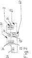
In der
Das zweite Element
In der
In der
In dem zweiten Element
In der
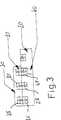
Eine Variante der Erfindung ist in den
In der
In der
Das Verriegelungselement
In der
In der
In den
In der
Der Aufbau des zweiten Elementes entspricht im Wesentlichen dem der
In der
Durch die Verstelleinrichtung
ZITATE ENTHALTEN IN DER BESCHREIBUNG QUOTES INCLUDE IN THE DESCRIPTION
Diese Liste der vom Anmelder aufgeführten Dokumente wurde automatisiert erzeugt und ist ausschließlich zur besseren Information des Lesers aufgenommen. Die Liste ist nicht Bestandteil der deutschen Patent- bzw. Gebrauchsmusteranmeldung. Das DPMA übernimmt keinerlei Haftung für etwaige Fehler oder Auslassungen.This list of the documents listed by the applicant has been generated automatically and is included solely for the better information of the reader. The list is not part of the German patent or utility model application. The DPMA assumes no liability for any errors or omissions.
Zitierte PatentliteraturCited patent literature
- US 5358469[0002]US 5358469[0002]
- US 7534220 B2[0003]US 7534220 B2[0003]
Claims (11)
Translated fromGermanPriority Applications (5)
| Application Number | Priority Date | Filing Date | Title |
|---|---|---|---|
| DE102010053176ADE102010053176A1 (en) | 2010-12-03 | 2010-12-03 | adjustment |
| US13/991,038US8915874B2 (en) | 2010-12-03 | 2011-11-29 | Adjusting device for a joint mechanism |
| CN201180066771.5ACN103338729B (en) | 2010-12-03 | 2011-11-29 | Adjusting device for a joint mechanism |
| PCT/EP2011/005974WO2012072231A1 (en) | 2010-12-03 | 2011-11-29 | Adjusting device for a joint mechanism |
| EP11790877.2AEP2645968B1 (en) | 2010-12-03 | 2011-11-29 | Adjusting device for a joint mechanism |
Applications Claiming Priority (1)
| Application Number | Priority Date | Filing Date | Title |
|---|---|---|---|
| DE102010053176ADE102010053176A1 (en) | 2010-12-03 | 2010-12-03 | adjustment |
Publications (1)
| Publication Number | Publication Date |
|---|---|
| DE102010053176A1true DE102010053176A1 (en) | 2012-06-06 |
Family
ID=45093678
Family Applications (1)
| Application Number | Title | Priority Date | Filing Date |
|---|---|---|---|
| DE102010053176AWithdrawnDE102010053176A1 (en) | 2010-12-03 | 2010-12-03 | adjustment |
Country Status (5)
| Country | Link |
|---|---|
| US (1) | US8915874B2 (en) |
| EP (1) | EP2645968B1 (en) |
| CN (1) | CN103338729B (en) |
| DE (1) | DE102010053176A1 (en) |
| WO (1) | WO2012072231A1 (en) |
Cited By (1)
| Publication number | Priority date | Publication date | Assignee | Title |
|---|---|---|---|---|
| DE102018132887A1 (en)* | 2018-12-19 | 2020-06-25 | Albrecht Gmbh | Dynamic orthotic joint |
Families Citing this family (9)
| Publication number | Priority date | Publication date | Assignee | Title |
|---|---|---|---|---|
| US10842653B2 (en) | 2007-09-19 | 2020-11-24 | Ability Dynamics, Llc | Vacuum system for a prosthetic foot |
| US12004988B2 (en)* | 2015-04-03 | 2024-06-11 | Alii R. Ontiki | Devices for and methods of measuring, enhancing and facilitating correct spinal alignment |
| US10085870B2 (en)* | 2015-06-22 | 2018-10-02 | Horsepower Technologies Inc. | Joint brace with improved range of motion stop |
| US10183744B2 (en)* | 2016-02-10 | 2019-01-22 | Lockheed Martin Corporation | Magnetic orientation detent |
| DE102017000902A1 (en)* | 2017-02-01 | 2018-08-02 | Rhefor Gbr (Vertretungsberechtigter Gesellschafter: Arno Mecklenburg, 10999 Berlin) | Electromagnetic locking element for a joint orthosis or joint prosthesis |
| WO2018147981A1 (en) | 2017-02-08 | 2018-08-16 | Parker-Hannifin Corporation | Legged mobility exoskeleton device with enhanced actuator mechanism employing magnetic coupling |
| DE102017128613A1 (en)* | 2017-12-01 | 2019-06-06 | Ottobock Se & Co. Kgaa | Adjustment device and orthosis with an adjustment |
| DE102019119645B4 (en) | 2019-07-19 | 2022-11-10 | Ottobock Se & Co. Kgaa | Orthopedic technical facility |
| DE202019003057U1 (en) | 2019-07-23 | 2019-07-31 | Preisler Group Gmbh | Orthosis for relief and / or fixation of a shoulder joint with a permanent magnetic forearm holder |
Citations (5)
| Publication number | Priority date | Publication date | Assignee | Title |
|---|---|---|---|---|
| US5358469A (en) | 1990-02-09 | 1994-10-25 | Ultraflex Systems, Inc. | Dynamic splint |
| US20020169402A1 (en)* | 2001-05-14 | 2002-11-14 | Hatton Bobby Joe | Articulating knee supports |
| DE10311187A1 (en)* | 2003-03-12 | 2004-10-14 | Otto Bock Healthcare Gmbh | Orthopedic aid with a locking device |
| DE202008015764U1 (en)* | 2008-11-27 | 2009-02-12 | Huntex Corporation | Adjusting device of a joint support apparatus |
| US7534220B2 (en) | 2003-09-29 | 2009-05-19 | Ossur Hf | Adjustable ergonomic brace |
Family Cites Families (5)
| Publication number | Priority date | Publication date | Assignee | Title |
|---|---|---|---|---|
| US6776442B2 (en)* | 2001-01-09 | 2004-08-17 | Strattec Security Corporation | Latch apparatus and method |
| EP1638117B1 (en)* | 2004-09-17 | 2007-08-15 | Voith Turbo Scharfenberg GmbH & Co. KG | Electromagnetic actuator |
| CN2829697Y (en)* | 2005-09-12 | 2006-10-25 | 唐丹 | Wire locked knee joint of knee/ankle/foot orthopedic device |
| CN201005821Y (en)* | 2007-03-22 | 2008-01-16 | 福州市第二医院 | Multifunctional elbow orthosis |
| DE102008027639A1 (en)* | 2008-06-06 | 2009-12-24 | Fior & Gentz Gmbh | Orthotic joint e.g. human anatomic knee joint, for use in orthopedic for forming leg brace of patient, has sensor unit including two sensors, and gyroscope for detecting person defined information in moving and/or resting state |
- 2010
- 2010-12-03DEDE102010053176Apatent/DE102010053176A1/ennot_activeWithdrawn
- 2011
- 2011-11-29EPEP11790877.2Apatent/EP2645968B1/enactiveActive
- 2011-11-29CNCN201180066771.5Apatent/CN103338729B/enactiveActive
- 2011-11-29USUS13/991,038patent/US8915874B2/enactiveActive
- 2011-11-29WOPCT/EP2011/005974patent/WO2012072231A1/enactiveApplication Filing
Patent Citations (5)
| Publication number | Priority date | Publication date | Assignee | Title |
|---|---|---|---|---|
| US5358469A (en) | 1990-02-09 | 1994-10-25 | Ultraflex Systems, Inc. | Dynamic splint |
| US20020169402A1 (en)* | 2001-05-14 | 2002-11-14 | Hatton Bobby Joe | Articulating knee supports |
| DE10311187A1 (en)* | 2003-03-12 | 2004-10-14 | Otto Bock Healthcare Gmbh | Orthopedic aid with a locking device |
| US7534220B2 (en) | 2003-09-29 | 2009-05-19 | Ossur Hf | Adjustable ergonomic brace |
| DE202008015764U1 (en)* | 2008-11-27 | 2009-02-12 | Huntex Corporation | Adjusting device of a joint support apparatus |
Cited By (2)
| Publication number | Priority date | Publication date | Assignee | Title |
|---|---|---|---|---|
| DE102018132887A1 (en)* | 2018-12-19 | 2020-06-25 | Albrecht Gmbh | Dynamic orthotic joint |
| DE102018132887B4 (en) | 2018-12-19 | 2024-10-31 | Albrecht Gmbh | Dynamic Orthotic Joint |
Also Published As
| Publication number | Publication date |
|---|---|
| US8915874B2 (en) | 2014-12-23 |
| EP2645968B1 (en) | 2014-03-12 |
| US20130253393A1 (en) | 2013-09-26 |
| EP2645968A1 (en) | 2013-10-09 |
| CN103338729B (en) | 2014-12-24 |
| WO2012072231A1 (en) | 2012-06-07 |
| CN103338729A (en) | 2013-10-02 |
Similar Documents
| Publication | Publication Date | Title |
|---|---|---|
| EP2645968B1 (en) | Adjusting device for a joint mechanism | |
| DE102006020777B4 (en) | Artificial joint | |
| EP1482875B1 (en) | Intravertebral prosthesis | |
| DE102013108574B4 (en) | Clamping claws for attachment to a slide rail of a surgical table | |
| EP2252176A2 (en) | Locking magnet closure | |
| EP1344506A1 (en) | Intervertebral prosthesis for the cervical spine | |
| WO2008006356A2 (en) | Magnetic quick-release buckle | |
| WO2005099589A1 (en) | Bone separator | |
| EP1707826A2 (en) | Ball locking bolt | |
| EP3346958B1 (en) | Pivoting-limitable biaxial joint | |
| DE102004030959A1 (en) | Sports shoe, in particular ski boot | |
| DE102013106092A1 (en) | Drawer with side frames and an adjustable front panel | |
| DE102013000557A1 (en) | Magnetic closure device for closing e.g. school bags, has unlocking lever that adjusts locking and unlocking position of connecting modules, and separates magnetic elements and locking element with low magnetic force | |
| WO2020094549A1 (en) | Device for supporting at least one arm of a user | |
| DE102016121202A1 (en) | Device for supporting an arm | |
| DE102012112716A1 (en) | Medical support arm | |
| EP3105080A1 (en) | Device for securing of load | |
| DE102010061161A1 (en) | Sliding door fitting for displacement of two sliding door wings of sliding door cabinet, has roller parts secured at wings, where shifting of fitting from flush position into displacement position by pressure on front face of one of wings | |
| DE102005014061B3 (en) | Locking device for door leaves with a door closer | |
| DE102016104877B4 (en) | Orthopaedic technical facility | |
| DE3425090C1 (en) | Locking device with at least one bolt or the like. And with a lock for this bolt | |
| WO2023135470A1 (en) | Continuous fine adjustment of the usage length of a wrist band | |
| DE102021130659A1 (en) | prosthetic wrist | |
| DE102004015870B4 (en) | shipping boxes | |
| DE102010015997A1 (en) | hinge |
Legal Events
| Date | Code | Title | Description |
|---|---|---|---|
| R016 | Response to examination communication | ||
| R016 | Response to examination communication | ||
| R082 | Change of representative | Representative=s name:GRAMM, LINS & PARTNER PATENT- UND RECHTSANWAEL, DE | |
| R119 | Application deemed withdrawn, or ip right lapsed, due to non-payment of renewal fee |