DE102010051620A1 - A method of estimating the sound velocity of an ultrasound image and an ultrasound diagnostic apparatus using the same - Google Patents
A method of estimating the sound velocity of an ultrasound image and an ultrasound diagnostic apparatus using the sameDownload PDFInfo
- Publication number
- DE102010051620A1 DE102010051620A1DE102010051620ADE102010051620ADE102010051620A1DE 102010051620 A1DE102010051620 A1DE 102010051620A1DE 102010051620 ADE102010051620 ADE 102010051620ADE 102010051620 ADE102010051620 ADE 102010051620ADE 102010051620 A1DE102010051620 A1DE 102010051620A1
- Authority
- DE
- Germany
- Prior art keywords
- image
- block
- raster
- blocks
- images
- Prior art date
- Legal status (The legal status is an assumption and is not a legal conclusion. Google has not performed a legal analysis and makes no representation as to the accuracy of the status listed.)
- Ceased
Links
- 238000002604ultrasonographyMethods0.000titleclaimsabstractdescription129
- 238000000034methodMethods0.000titleclaimsabstractdescription26
- 238000000605extractionMethods0.000claimsdescription17
- 239000000523sampleSubstances0.000claimsdescription12
- 230000005540biological transmissionEffects0.000claimsdescription8
- 239000000284extractSubstances0.000claimsdescription7
- 238000010191image analysisMethods0.000claimsdescription6
- 238000010586diagramMethods0.000description11
- 238000009966trimmingMethods0.000description6
- 238000004458analytical methodMethods0.000description2
- 238000003745diagnosisMethods0.000description2
- 238000003384imaging methodMethods0.000description2
- 238000012986modificationMethods0.000description2
- 230000004048modificationEffects0.000description2
- 238000006467substitution reactionMethods0.000description2
- BUHVIAUBTBOHAG-FOYDDCNASA-N(2r,3r,4s,5r)-2-[6-[[2-(3,5-dimethoxyphenyl)-2-(2-methylphenyl)ethyl]amino]purin-9-yl]-5-(hydroxymethyl)oxolane-3,4-diolChemical compoundCOC1=CC(OC)=CC(C(CNC=2C=3N=CN(C=3N=CN=2)[C@H]2[C@@H]([C@H](O)[C@@H](CO)O2)O)C=2C(=CC=CC=2)C)=C1BUHVIAUBTBOHAG-FOYDDCNASA-N0.000description1
- 238000007792additionMethods0.000description1
- 230000001174ascending effectEffects0.000description1
- 239000000969carrierSubstances0.000description1
- 238000010276constructionMethods0.000description1
- 230000001066destructive effectEffects0.000description1
- 230000000694effectsEffects0.000description1
- 230000001902propagating effectEffects0.000description1
- 230000005855radiationEffects0.000description1
Images

Classifications
- A—HUMAN NECESSITIES
- A61—MEDICAL OR VETERINARY SCIENCE; HYGIENE
- A61B—DIAGNOSIS; SURGERY; IDENTIFICATION
- A61B8/00—Diagnosis using ultrasonic, sonic or infrasonic waves
- A61B8/52—Devices using data or image processing specially adapted for diagnosis using ultrasonic, sonic or infrasonic waves
- A61B8/5215—Devices using data or image processing specially adapted for diagnosis using ultrasonic, sonic or infrasonic waves involving processing of medical diagnostic data
- A61B8/5223—Devices using data or image processing specially adapted for diagnosis using ultrasonic, sonic or infrasonic waves involving processing of medical diagnostic data for extracting a diagnostic or physiological parameter from medical diagnostic data
- A—HUMAN NECESSITIES
- A61—MEDICAL OR VETERINARY SCIENCE; HYGIENE
- A61B—DIAGNOSIS; SURGERY; IDENTIFICATION
- A61B8/00—Diagnosis using ultrasonic, sonic or infrasonic waves
- G—PHYSICS
- G01—MEASURING; TESTING
- G01N—INVESTIGATING OR ANALYSING MATERIALS BY DETERMINING THEIR CHEMICAL OR PHYSICAL PROPERTIES
- G01N29/00—Investigating or analysing materials by the use of ultrasonic, sonic or infrasonic waves; Visualisation of the interior of objects by transmitting ultrasonic or sonic waves through the object
- G01N29/04—Analysing solids
- G01N29/06—Visualisation of the interior, e.g. acoustic microscopy
- G01N29/0654—Imaging
- G01N29/0672—Imaging by acoustic tomography
- G—PHYSICS
- G01—MEASURING; TESTING
- G01N—INVESTIGATING OR ANALYSING MATERIALS BY DETERMINING THEIR CHEMICAL OR PHYSICAL PROPERTIES
- G01N29/00—Investigating or analysing materials by the use of ultrasonic, sonic or infrasonic waves; Visualisation of the interior of objects by transmitting ultrasonic or sonic waves through the object
- G01N29/04—Analysing solids
- G01N29/07—Analysing solids by measuring propagation velocity or propagation time of acoustic waves
- G—PHYSICS
- G01—MEASURING; TESTING
- G01S—RADIO DIRECTION-FINDING; RADIO NAVIGATION; DETERMINING DISTANCE OR VELOCITY BY USE OF RADIO WAVES; LOCATING OR PRESENCE-DETECTING BY USE OF THE REFLECTION OR RERADIATION OF RADIO WAVES; ANALOGOUS ARRANGEMENTS USING OTHER WAVES
- G01S15/00—Systems using the reflection or reradiation of acoustic waves, e.g. sonar systems
- G01S15/88—Sonar systems specially adapted for specific applications
- G01S15/89—Sonar systems specially adapted for specific applications for mapping or imaging
- G01S15/8906—Short-range imaging systems; Acoustic microscope systems using pulse-echo techniques
- G—PHYSICS
- G01—MEASURING; TESTING
- G01S—RADIO DIRECTION-FINDING; RADIO NAVIGATION; DETERMINING DISTANCE OR VELOCITY BY USE OF RADIO WAVES; LOCATING OR PRESENCE-DETECTING BY USE OF THE REFLECTION OR RERADIATION OF RADIO WAVES; ANALOGOUS ARRANGEMENTS USING OTHER WAVES
- G01S7/00—Details of systems according to groups G01S13/00, G01S15/00, G01S17/00
- G01S7/52—Details of systems according to groups G01S13/00, G01S15/00, G01S17/00 of systems according to group G01S15/00
- G01S7/52017—Details of systems according to groups G01S13/00, G01S15/00, G01S17/00 of systems according to group G01S15/00 particularly adapted to short-range imaging
- G01S7/52023—Details of receivers
- G01S7/52036—Details of receivers using analysis of echo signal for target characterisation
- G01S7/52042—Details of receivers using analysis of echo signal for target characterisation determining elastic properties of the propagation medium or of the reflective target
- G—PHYSICS
- G01—MEASURING; TESTING
- G01S—RADIO DIRECTION-FINDING; RADIO NAVIGATION; DETERMINING DISTANCE OR VELOCITY BY USE OF RADIO WAVES; LOCATING OR PRESENCE-DETECTING BY USE OF THE REFLECTION OR RERADIATION OF RADIO WAVES; ANALOGOUS ARRANGEMENTS USING OTHER WAVES
- G01S7/00—Details of systems according to groups G01S13/00, G01S15/00, G01S17/00
- G01S7/52—Details of systems according to groups G01S13/00, G01S15/00, G01S17/00 of systems according to group G01S15/00
- G01S7/52017—Details of systems according to groups G01S13/00, G01S15/00, G01S17/00 of systems according to group G01S15/00 particularly adapted to short-range imaging
- G01S7/52046—Techniques for image enhancement involving transmitter or receiver
- G01S7/52049—Techniques for image enhancement involving transmitter or receiver using correction of medium-induced phase aberration
- G—PHYSICS
- G01—MEASURING; TESTING
- G01S—RADIO DIRECTION-FINDING; RADIO NAVIGATION; DETERMINING DISTANCE OR VELOCITY BY USE OF RADIO WAVES; LOCATING OR PRESENCE-DETECTING BY USE OF THE REFLECTION OR RERADIATION OF RADIO WAVES; ANALOGOUS ARRANGEMENTS USING OTHER WAVES
- G01S7/00—Details of systems according to groups G01S13/00, G01S15/00, G01S17/00
- G01S7/52—Details of systems according to groups G01S13/00, G01S15/00, G01S17/00 of systems according to group G01S15/00
- G01S7/52017—Details of systems according to groups G01S13/00, G01S15/00, G01S17/00 of systems according to group G01S15/00 particularly adapted to short-range imaging
- G01S7/5205—Means for monitoring or calibrating
- G—PHYSICS
- G16—INFORMATION AND COMMUNICATION TECHNOLOGY [ICT] SPECIALLY ADAPTED FOR SPECIFIC APPLICATION FIELDS
- G16H—HEALTHCARE INFORMATICS, i.e. INFORMATION AND COMMUNICATION TECHNOLOGY [ICT] SPECIALLY ADAPTED FOR THE HANDLING OR PROCESSING OF MEDICAL OR HEALTHCARE DATA
- G16H50/00—ICT specially adapted for medical diagnosis, medical simulation or medical data mining; ICT specially adapted for detecting, monitoring or modelling epidemics or pandemics
- G16H50/30—ICT specially adapted for medical diagnosis, medical simulation or medical data mining; ICT specially adapted for detecting, monitoring or modelling epidemics or pandemics for calculating health indices; for individual health risk assessment
Landscapes
- Engineering & Computer Science (AREA)
- Physics & Mathematics (AREA)
- Health & Medical Sciences (AREA)
- Life Sciences & Earth Sciences (AREA)
- General Physics & Mathematics (AREA)
- Radar, Positioning & Navigation (AREA)
- Remote Sensing (AREA)
- General Health & Medical Sciences (AREA)
- Pathology (AREA)
- Computer Networks & Wireless Communication (AREA)
- Acoustics & Sound (AREA)
- Public Health (AREA)
- Medical Informatics (AREA)
- Biomedical Technology (AREA)
- Surgery (AREA)
- Animal Behavior & Ethology (AREA)
- Nuclear Medicine, Radiotherapy & Molecular Imaging (AREA)
- Radiology & Medical Imaging (AREA)
- Analytical Chemistry (AREA)
- Heart & Thoracic Surgery (AREA)
- Immunology (AREA)
- Molecular Biology (AREA)
- Biochemistry (AREA)
- Biophysics (AREA)
- Chemical & Material Sciences (AREA)
- Veterinary Medicine (AREA)
- Physiology (AREA)
- Computer Vision & Pattern Recognition (AREA)
- Data Mining & Analysis (AREA)
- Databases & Information Systems (AREA)
- Epidemiology (AREA)
- Primary Health Care (AREA)
- Ultra Sonic Daignosis Equipment (AREA)
Abstract
Translated fromGermanDescription
Translated fromGermanQuerverweis zu verwandter AnmeldungCross-reference to related logon
Diese Anmeldung nimmt den Nutzen der
Hintergrund der ErfindungBackground of the invention
1. Technisches Feld1. Technical field
Die vorliegende Erfindung bezieht sich auf ein Verfahren zum Abschätzen der Schallgeschwindigkeit eines Ultraschallbildes und auf eine Ultraschalldiagnosevorrichtung, die dieses verwendet.The present invention relates to a method of estimating the velocity of sound of an ultrasound image and to an ultrasound diagnostic apparatus using the same.
2. Beschreibung des verwandten Standes der Technik2. Description of the Related Art
Eine Ultraschalldiagnosevorrichtung ist eine der wichtigsten Diagnosevorrichtungen, die in verschiedenen Feldern verwendet wird. Insbesondere sind die Ultraschalldiagnosevorrichtungen im Medizinsektor weit verbreitet aufgrund ihrer nicht invasiven und nicht zerstörenden Eigenschaften im Hinblick auf Objekte eingesetzt. In letzter Zeit wird ein Hochleistungsultraschallsystem verwendet, um zweidimensionale oder dreidimensionale Bilder des Inneren von Objekten zu erzeugen.An ultrasound diagnostic device is one of the most important diagnostic devices used in various fields. In particular, ultrasound diagnostic devices are widely used in the medical sector because of their non-invasive and non-destructive properties with respect to objects. Recently, a high power ultrasound system has been used to generate two-dimensional or three-dimensional images of the interior of objects.
Im Allgemeinen empfängt die Ultraschalldiagnosevorrichtung Echowellen, die erhalten werden, indem ein Teil der von einem Ultraschalltastkopf übertragenen. Ultraschallwellen von einem Änderungspunkt (Änderungsoberfläche) einer Gewebestruktur in einem Objekt reflektiert wird, und erzeugt ein tomographisches Bild eines Objektes auf Basis der Echowellen.In general, the ultrasound diagnostic device receives echo waves obtained by subtracting part of the ultrasound probe transmitted. Ultrasonic waves from a change point (change surface) of a tissue structure is reflected in an object, and generates a tomographic image of an object based on the echo waves.
Das erzeugte Ultraschallbild kann durch sich ausbreitende Ultraschallwellen, die von dem Ultraschalltastkopf in das Gewebe des Objekts emittiert werden, und durch das Erfassen der reflektierten Wellen (Echowellen), die zurückgesandt werden, indem sie von dem Gewebe reflektiert werden, erzeugt werden.The generated ultrasound image may be generated by propagating ultrasonic waves emitted from the ultrasound probe into the tissue of the subject and by detecting the reflected waves (echo waves) that are returned by being reflected from the tissue.
Im Stand der Technik erzeugt die Ultraschalldiagnosevorrichtung die Ultraschallbilder, indem die oben genannten Prozesse durchgeführt werden, um eine Diagnose des Gewebes des menschlichen Körpers zu erstellen. In diesem Fall fokussiert die Ultraschalldiagnosevorrichtung Strahlen unter der Annahme, dass die Ultraschalldiagnosevorrichtung die gleiche Schallgeschwindigkeit (zum Beispiel etwa 1.540 m/s) in allen Bereichen des Gewebes im menschlichen Körper hat. Jedoch weist das Gewebe im menschlichen Körper inhärente Schallgeschwindigkeiten entsprechend der jeweiligen Trägersubstanz auf.In the prior art, the ultrasound diagnostic apparatus generates the ultrasound images by performing the above-mentioned processes to make a diagnosis of the tissue of the human body. In this case, the ultrasound diagnostic device focuses rays assuming that the ultrasound diagnostic device has the same sound velocity (for example, about 1540 m / s) in all regions of the tissue in the human body. However, tissue in the human body has inherent sonic velocities corresponding to the particular vehicle.
Aus diesem Grund kann es zu einer Differenz zwischen der wirklichen Schallgeschwindigkeit eines jeden Gewebes im menschlichen Körper und der angenommenen Schallgeschwindigkeit kommen. Die Differenz kann einen Effekt auf die reflektierte Welle, die durch die Reflektion an dem jeweiligen Gewebe im menschlichen Körper zurückgesendet werden, haben.For this reason, there may be a difference between the actual speed of sound of each tissue in the human body and the assumed speed of sound. The difference may have an effect on the reflected wave returned by the reflection at the respective tissue in the human body.
Wird die Differenz zwischen den tatsächlichen Schallgeschwindigkeiten in verschiedenen Arten von Gewebe im menschlichen Körper und der angenommenen Schallgeschwindigkeiten erhöht, kann sich daher auch der Unterschied zwischen den reflektierten Wellen erhöhen. Als Resultat werden die Strahlen, die von dem Gewebe im menschlichen Körper reflektiert werden, defokussiert, was ein Problem der Verminderung der Auflösung und des Gewebekontrasts durch Verzerrung der Bilder verursacht.Therefore, increasing the difference between the actual sound velocities in different types of tissue in the human body and the assumed sound velocities may increase the difference between the reflected waves. As a result, the rays reflected from the tissue in the human body are defocused, causing a problem of lowering the resolution and tissue contrast by distorting the images.
Daher besteht, um höher aufgelöste Ultraschallbilder für eine genauere Diagnose zu erhalten, die Notwendigkeit, die wirklichen Schallgeschwindigkeiten eines jeden Teils des menschlichen Körpers schneller und genauer abzuschätzen und sie für die Ultraschalldiagnosevorrichtung zu verwenden.Therefore, to obtain higher resolution ultrasound images for a more accurate diagnosis, there is a need to more quickly and accurately estimate the true sound velocities of each part of the human body and to use them for the ultrasound diagnostic device.
Zusammenfassung der ErfindungSummary of the invention
Ein Aspekt der vorliegenden Erfindung ist das Bereitstellen eines Verfahrens zum Abschätzen der Schallgeschwindigkeit eines Ultraschallbildes in Echtzeit, indem Ultraschallbilder aufgeteilt werden und Analyseregionen der aufgeteilten Bilder definiert werden, sowie einer Ultraschalldiagnosevorrichtung, die dieses verwendet.One aspect of the present invention is to provide a method of estimating the speed of sound of an ultrasound image in real time by dividing ultrasound images and defining analysis regions of the split images, and an ultrasound diagnostic apparatus using the same.
Entsprechend einer Ausführungsform der vorliegenden Erfindung wird ein Verfahren zum Abschätzen der Schallgeschwindigkeit eines Ultraschallbildes bereitgestellt, beinhaltend: (A) Aufteilen eines jeden der Ultraschallbilder einer Vielzahl von Eingangsrasterbildern in eine Mehrzahl von Blöcken; (B) Extrahieren von Konturen von Ultraschallbildern entsprechend jedem Block des in eine Vielzahl von Blöcken aufgeteilten einen Rasterbilds aus den Ultraschallbildern einer Vielzahl aufgeteilter Rasterbilder; (C) Berechnen und Analysieren der mittleren Leuchtdichtewerte jedes Blocks, um optimale Blöcke aus einer Sequenz von Blöcken auszuwählen, die den maximalen Leuchtdichtewert unter den mittleren Leuchtdichtewerten jedes Blocks aufweisen, wenn die Konturextrahierung für jeden Block abgeschlossen ist; (D) Bestimmen der optimalen Anzahl von Blöcken entsprechend der mittleren Leuchtdichte der analysierten Rasterbilder, indem die mittleren Leuchtdichtewerte der analysierten Rasterbilder berechnet werden, wobei die mittleren Leuchtdichtewerte jedes analysierten Blocks verwendet werden, und Auswählen so vieler optimaler Blöcke wie die optimale Blockanzahl; und (E) Auswählen des Rasterbildes als optimales Rasterbild, das zu den optimalen Blöcken gehört, die den maximalen Leuchtdichtewert unter den optimalen Blöcken jedes Rasterbildes aufweisen, nach dem Vergleichen der ausgewählten optimalen Blöcke mit den optimalen Blöcken der verbleibenden Rasterbilder, und Abschätzen und Verwenden der Schallgeschwindigkeit des optimalen Rasterbildes als die wirkliche Schallgeschwindigkeit.According to an embodiment of the present invention, there is provided a method of estimating the velocity of sound of an ultrasound image, comprising: (A) dividing each of the ultrasound images of a plurality of input raster images into a plurality of blocks; (B) extracting contours of ultrasound images corresponding to each block of the raster image divided into a plurality of blocks from the ultrasound images of a plurality of divided raster images; (C) calculating and analyzing the average luminance values of each block to select optimal blocks from a sequence of blocks having the maximum luminance value among the average luminance values of each block when the contour extraction for each block is completed; (D) Determine the optimal number of blocks corresponding to the average luminance of the analyzed raster images by calculating the average luminance values of the analyzed raster images using the average luminance values of each analyzed block, and selecting as many optimal blocks as the optimum block number; and (E) selecting the raster image as the optimum raster image belonging to the optimum blocks having the maximum luminance value among the optimum blocks of each raster image after comparing the selected optimum blocks with the optimum blocks of the remaining raster images, and estimating and using the raster image Speed of sound of the optimum raster image as the actual speed of sound.
Schritt (B) extrahiert die Konturen der Ultraschallbilder eines jeden Blocks, indem ein Differenzbildfilter auf jeden Block angewendet wird, um die Leuchtdichtewerte jedes Pixels für jeden Block zu berechnen.Step (B) extracts the contours of the ultrasound images of each block by applying a difference image filter to each block to calculate the luminance values of each pixel for each block.
Der Differenzbildfilter, der auf jeden Block angewendet wird, berechnet den Absolutbetrag der Differenz der Leuchtdichtewerte zwischen den Pixeln, die an ein Pixel angrenzen, um den maximalen Absolutbetrag unter den Absolutbeträgen als den Leuchtdichtewert des einen Pixels zu bestimmen.The difference image filter applied to each block calculates the absolute value of the difference of the luminance values between the pixels adjoining one pixel to determine the maximum absolute value among the absolute values as the luminance value of the one pixel.
Schritt (C) berechnet die mittleren Leuchtdichtewerte jedes Blocks, indem die Gesamtsumme der Leuchtdichtewerte jedes Pixels für jeden Block durch die Gesamtpixelzahl jedes Blocks geteilt wird.Step (C) calculates the average luminance values of each block by dividing the sum total of the luminance values of each pixel for each block by the total pixel number of each block.
Schritt (D) beinhaltet: (D-1) Berechnen der mittleren Leuchtdichtewerte der analysierten Rasterbilder, indem die mittleren Leuchtdichtewerte jedes analysierten Blocks verwendet werden; (D-2) Bestimmen der optimalen Blockanzahl entsprechend der mittleren Leuchtdichtewerte der analysierten Rasterbilder; und (D-3) Auswählen so vieler optimaler Blöcke wie die bestimmte optimale Blockanzahl in Reihenfolge der höchsten Leuchtdichtewerte unter den mittleren Leuchtdichtewerten jedes Blocks.Step (D) includes: (D-1) calculating the average luminance values of the analyzed raster images by using the average luminance values of each analyzed block; (D-2) determining the optimal block number according to the average luminance values of the analyzed raster images; and (D-3) selecting as many optimal blocks as the determined optimum block number in order of the highest luminance values among the average luminance values of each block.
Schritt (D-1) berechnet die mittleren Leuchtdichtewerte der analysierten Rasterbilder, indem die Gesamtsumme der mittleren Leuchtdichtewerte jedes analysierten Blocks durch die Gesamtanzahl der Blöcke der analysierten Rasterbilder geteilt wird.Step (D-1) calculates the average luminance values of the analyzed raster images by dividing the sum total of the average luminance values of each analyzed block by the total number of blocks of the analyzed raster images.
Schritt (E) beinhaltet: (E-1) Vergleichender ausgewählten optimalen Blöcke mit den optimalen Blöcken der übrigen Rasterbilder; (E-2) Auswählen des Rasterbildes, das den optimalen Blöcken, die die maximalen Leuchtdichtewerte unter den optimalen Blöcken jedes Rasterbildes aufweisen, zugehörige Rasterbild als das optimale Rasterbild; und (E-3) Abschätzen und Verwenden der Schallgeschwindigkeit des optimalen Rasterbildes als die wirkliche Schallgeschwindigkeit.Step (E) includes: (E-1) comparing the selected optimal blocks with the optimal blocks of the remaining raster images; (E-2) selecting the raster image corresponding to the optimum blocks having the maximum luminance values among the optimum blocks of each raster image as raster image as the optimum raster image; and (E-3) estimating and using the sound velocity of the optimum raster image as the true sound velocity.
Entsprechend einer Ausführungsform der vorliegenden Erfindung wird eine Ultraschalldiagnosevorrichtung bereitgestellt, beinhaltend: einen Ultraschallsender, der entsprechend einem Steuersignal Sendesignale erzeugt und die Sendesignale in Ultraschallstrahlen umwandelt; einen Ultraschalltastkopf, der die Ultraschallstrahlen zu Objekten aussendet und reflektierte Wellen, die von den Objekten zurückgesandt werden, empfängt; einen Ultraschallempfänger, der die reflektierte Welle in elektrische Signale umwandelt, um die empfangenen Signale zu erzeugen; einen Bildprozessor, der die empfangenen Signale in eine Mehrzahl von Schallgeschwindigkeiten aufteilt und extrahiert und die Ultraschallbilder der Mehrzahl von Rasterbildern erzeugt; eine Schallgeschwindigkeitsbestimmungseinheit, die die Ultraschallbilder eines Rasterbildes aus den Ultraschallbildern einer Mehrzahl von Rasterbildern, die von dem Bildprozessor erzeugt werden, in eine Mehrzahl von Blöcke aufteilt, um Konturen zu extrahieren, die Leuchtdichtewerte jedes Blocks analysiert, um die optimale Blockanzahl zu bestimmen, und das optimale Rasterbild auswählt, indem so viele optimale Blöcke wie die optimale Blockanzahl ausgewählt und auf das verbleibende Rasterbild angewendet werden, um die Schallgeschwindigkeit des optimalen Rasterbildes als die wirkliche Schallgeschwindigkeit der reflektierten Welle abzuschätzen; und ein Steuergerät, das eine Steuerung ausführt, um das Ultraschallbildsteuersignal zu erzeugen, den Ultraschallstrahl entsprechend dem Steuerungssignal zu erzeugen und die reflektierte Welle des emittierten Ultraschallstrahls zu empfangen, um die Ultraschallbilder der Mehrzahl von Rasterbildern zu erzeugen, das Ultraschallbild eines Rasterbildes aus den Ultraschallbildern der Mehrzahl der erzeugten Ultraschallbilder in eine Mehrzahl von Blöcken aufzuteilen, um Konturen zu extrahieren, die Leuchtdichtewerte jedes Blocks zu analysieren, um die optimale Blockanzahl zu bestimmen, und um das optimale Rasterbild auszuwählen, indem so viele optimale Blöcke wie die optimale Blockanzahl ausgewählt und auf das verbleibende Rasterbild angewendet werden, um die Schallgeschwindigkeit des optimalen Rasterbildes als die wirkliche Schallgeschwindigkeit der reflektierten Welle abzuschätzen.According to an embodiment of the present invention, there is provided an ultrasonic diagnostic apparatus including: an ultrasonic transmitter that generates transmit signals in accordance with a control signal and converts the transmit signals into ultrasonic beams; an ultrasonic probe that emits the ultrasonic beams to objects and receives reflected waves returned from the objects; an ultrasonic receiver that converts the reflected wave into electrical signals to produce the received signals; an image processor that divides and extracts the received signals into a plurality of sound velocities and generates the ultrasound images of the plurality of raster images; a sound velocity determining unit that divides the ultrasonic images of a raster image from the ultrasound images of a plurality of raster images generated by the image processor into a plurality of blocks to extract contours, analyzes the luminance values of each block to determine the optimum block number, and select optimal raster image by selecting as many optimal blocks as the optimum block number and applying it to the remaining raster image to estimate the sound velocity of the optimum raster image as the actual sound velocity of the reflected wave; and a controller that performs control to generate the ultrasonic image control signal, generate the ultrasonic beam according to the control signal and receive the reflected wave of the emitted ultrasonic beam to generate the ultrasonic images of the plurality of raster images, the ultrasonic image of a raster image from the ultrasonic images of the Divide a plurality of the generated ultrasound images into a plurality of blocks to extract contours, analyze the luminance values of each block to determine the optimal block number, and to select the optimal raster image by selecting as many optimal blocks as the optimal block number and placing them on the remaining raster image to estimate the sound velocity of the optimum raster image as the actual sound velocity of the reflected wave.
Die Ultraschalldiagnosevorrichtung beinhaltet weiterhin eine Datenausgabeeinheit, die die Ultraschallbilder ausgibt.The ultrasound diagnostic apparatus further includes a data output unit that outputs the ultrasound images.
Der Bildprozessor beinhaltet: ein Bildextraktionsmodul, das die empfangenen Signale in die Mehrzahl der Schallgeschwindigkeiten aufteilt, um die Mehrzahl der Bildsignale zu extrahieren; und ein Bilderzeugungsmodul, das die Ultraschallbilder der Mehrzahl von Rasterbildern auf Grundlage der Mehrzahl von Bildsignalen erzeugt.The image processor includes: an image extraction module that divides the received signals into the plurality of sound velocities to extract the plurality of image signals; and an imaging module that captures the ultrasound images of Produces a plurality of raster images based on the plurality of image signals.
Die Schallgeschwindigkeitbestimmungseinheit beinhaltet: ein Bildteilungsmodul, das die Ultraschallbilder eines Rasterbildes der Ultraschallbilder der Mehrzahl von Rasterbildern, die von dem Bildprozessor erzeugt werden, in die Mehrzahl von Blöcken aufteilt; ein Konturenextraktionsmodul, das die Konturen der Ultraschallbilder jedes Blocks extrahiert, indem der Differenzbildfilter auf die Ultraschallbilder jedes Blocks eines aus der Mehrzahl von Rasterbildern angewendet wird, um die Leuchtdichtewerte für jedes Pixel jedes Blocks zu berechnen; ein Bildanalysemodul, das den mittleren Leuchtdichtewert jedes Blocks berechnet, um die Ultraschallbilder jedes Blocks zu digitalisieren und zu analysieren, wenn die Konturextraktion jedes Blocks abgeschlossen ist; ein Bildvergleichsmodul, das die optimale Blockanzahl entsprechend des mittleren Leuchtdichtewertes der analysierten Rasterbilder bestimmt, um so viele der optimalen Blöcke wie die ermittelte optimale Blockanzahl in einer Reihenfolge der höchsten Werte unter den mittleren Leuchtdichtewerten jedes Blocks auszuwählen, und das die optimalen Blöcke jedes Rasterbildes vergleicht, indem die Positionen der optimalen Blöcke auf die übrigen Rasterbilder angewendet werden, um die optimalen Blöcke, die die höchsten Leuchtdichtewerte haben, auszuwählen; und ein Schallgeschwindigkeitsbestimmungsmodul, das das Rasterbild, das zu den optimalen Blöcken gehört, die die höchsten Leuchtdichtewerte haben, als das optimale Rasterbild auswählt, um das ausgewählte Rasterbild als die wirkliche Schallgeschwindigkeit der reflektierten Welle abzuschätzen.The sound velocity determination unit includes: an image division module that divides the ultrasonic images of a raster image of the ultrasound images of the plurality of raster images generated by the image processor into the plurality of blocks; a contour extraction module that extracts the contours of the ultrasound images of each block by applying the difference image filter to the ultrasound images of each block of one of the plurality of raster images to calculate the luminance values for each pixel of each block; an image analysis module that calculates the average luminance value of each block to digitize and analyze the ultrasound images of each block when the contour extraction of each block is completed; an image comparison module that determines the optimum block number corresponding to the average luminance value of the analyzed raster images so as to select as many of the optimum blocks as the determined optimum block number in an order of the highest values among the average luminance values of each block and comparing the optimum blocks of each raster image; by applying the positions of the optimum blocks to the remaining raster images to select the optimal blocks having the highest luminance values; and a sound velocity determination module that selects the raster image belonging to the optimal blocks having the highest luminance values as the optimum raster image to estimate the selected raster image as the actual sound velocity of the reflected wave.
Kurze Beschreibung der ZeichnungenBrief description of the drawings
Beschreibung der bevorzugten AusführungsformenDescription of the Preferred Embodiments
Verschiedene Eigenschaften und Vorteile der vorliegenden Erfindung werden aus der folgenden Beschreibung unter Bezugnahme auf die begleitenden Zeichnungen deutlicher werden.Various features and advantages of the present invention will become more apparent from the following description with reference to the accompanying drawings.
Ausdrücke oder Wörter, die in der vorliegenden Beschreibung und den Ansprüchen benutzt werden, sollten nicht anhand ihrer allgemeinen und lexikalischen Bedeutung ausgelegt werden und sollten als die Bedeutung und das Konzept, das die technische Idee der vorliegenden Erfindung trifft, ausgelegt werden, auf Basis des Grundsatzes, dass die gegenwärtigen Erfinder die Vorstellungen der Ausdrücke geeignet definieren können, um ihre eigene Erfindung auf die beste Weise zu erläutern.Terms or words used in the present specification and claims should not be construed in terms of their general and lexical meaning and should be construed as the meaning and concept that meets the technical idea of the present invention based on the principle in that the present inventors can properly define the ideas of the terms to explain their own invention in the best way.
Die obigen und andere Gegenstände, Eigenschaften und Vorteile der vorliegenden Erfindung werden aus der folgenden detaillierten Beschreibung, in Verbindung mit den begleitenden Zeichnungen genommen, deutlicher verstanden werden. Zum Hinzufügen von Bezugszeichen zu Bestandteilen in den Zeichnungen ist in der Beschreibung zu sagen, dass gleiche Bezugszeichen gleiche Bestandteile bezeichnen, auch wenn die Bestandteile in unterschiedlichen Zeichnungen gezeigt sind. Weiterhin wird, wenn festgestellt wird, dass die detaillierte Beschreibung des bekannten Standes der Technik mit Bezug auf die vorliegende Erfindung das wesentliche der vorliegenden Erfindung verdecken könnte, die detaillierte Beschreibung davon weggelassen werden.The above and other objects, features, and advantages of the present invention will become more apparent from the following detailed description taken in conjunction with the accompanying drawings. For adding reference numerals to components in the drawings, in the description, like reference characters designate like components, even though the components are shown in different drawings. Furthermore, if it is determined that the detailed description of the known art relating to the present invention could obscure the essence of the present invention, the detailed description thereof will be omitted.
Im Weiteren werden bevorzugte Ausführungsformen der vorliegenden Erfindung detailliert unter Bezugnahme auf die begleitenden Zeichnungen beschrieben werden.Hereinafter, preferred embodiments of the present invention will be described in detail with reference to the accompanying drawings.
Darüber hinaus wird für die Zweckdienlichkeit der Beschreibung in der vorliegenden Erfindung angenommen, dass Schallgeschwindigkeiten von Ultraschallwellen, die zu Objekten ausgesendet werden, als zwischen 1400 m/s bis 1590 m/s liegend angenommen werden, und dass empfangene Signale, die durch Reflektion daran zurückgesandt werden, in 10 m/s aufgeteilt werden, um Ultraschallbilder von 20 Rasterbildern aus 20 empfangenen Signalen zu erhalten.Moreover, for the convenience of the description in the present invention, it is assumed that sound velocities of ultrasonic waves emitted to objects are assumed to be between 1400 m / s to 1590 m / s, and that received signals are sent back by reflection therefrom be divided into 10 m / s to ultrasound images of 20 Raster images obtained from 20 received signals.
Unter Bezugnahme auf
Beim Beschneiden der Ultraschallbilder (S110) werden die Ultraschallbilder beschnitten, damit sie eine vorbestimmte Größe haben.When trimming the ultrasound images (S110), the ultrasound images are trimmed to have a predetermined size.
Das Beschneiden der Ultraschallbilder ist hauptsächlich, um unnötige Teile zu entfernen, wenn Ultraschallbilder in verschiedenen Formen, u. a. einer Fächerform, vorliegen, und wird in gleicher Weise auf die Ultraschallbilder von 20 Rasterbildern angewendet.The trimming of the ultrasound images is primarily to remove unnecessary parts when ultrasound images in various shapes, u. a. a fan shape, and is applied equally to the ultrasound images of 20 raster images.
Zusätzlich kann das Beschneiden der Ultraschallbildern (S110) ausgestaltet sein, um einen Benutzermodus und einen automatischen Modus zu beinhalten. Zum Beispiel stellt ein Benutzer im Fall des Benutzermodus direkt Teile, die zu beschneiden sind, ein, um sie von Hand zu beschneiden, wobei er die dargestellten Ultraschallbilder sieht, während im Fall des Automatikmodus automatisch Teile, die beschnitten werden sollen, beschnitten werden, indem sie im vorhinein zum Konstruktionszeitpunkt ausgewählt werden.In addition, the trimming of the ultrasound images (S110) may be configured to include a user mode and an automatic mode. For example, in the case of the user mode, a user directly sets parts to be trimmed to crop them by hand, seeing the displayed ultrasound images, while in the case of the automatic mode automatically crops trimmed parts by trimming they are selected in advance at the time of construction.
Die beschnittenen Ultraschallbilder werden beim Aufteilen der Ultraschallbilder (S120) in eine Mehrzahl von Blöcken (zum Beispiel N × M) aufgeteilt.The trimmed ultrasound images are divided into a plurality of blocks (for example, N × M) in dividing the ultrasound images (S120).
Die Ultraschallbilder, die bei Schritt S110 beschnitten wurden, werden, wie in
In diesem Fall werden die Breite und die Höhe jedes Blockes durch die folgenden Gleichungen (1) und (2) zum Zeitpunkt des Teilens der beschnittenen Ultraschallbilder berechnet.
In Gleichung (1) bezeichnet INC_W die Breite jedes Blocks, R_size ist eine Breite des beschnittenen Ultraschallbildes, und N bezeichnet die Anzahl der Blöcke in der Reihe.In equation (1), INC_W denotes the width of each block, R_size is a width of the trimmed ultrasound image, and N denotes the number of blocks in the row.
Zusätzlich bezeichnet in Gleichung (2) INC_H die Höhen jedes Blockes, C_size bezeichnet die Höhen der beschnittenen Ultraschallbilder und M bezeichnet die Anzahl Blöcke der Spalte.In addition, in equation (2), INC_H denotes the heights of each block, C_size denotes the heights of the trimmed ultrasonic images, and M denotes the number of blocks of the column.
Entsprechend den Gleichungen (1) und (2) werden die Breiten jedes Blockes berechnet, indem die Breiten der beschnittenen Ultraschallbilder durch die Anzahl der Blöcke in einer Reihe geteilt werden und die Höhen jedes Blockes werden berechnet, indem die Höhen des beschnittenen Ultraschallbildes durch die Anzahl der Blöcke in der Spalte geteilt werden.According to equations (1) and (2), the widths of each block are calculated by dividing the widths of the trimmed ultrasound images by the number of blocks in a row, and the heights of each block are calculated by dividing the heights of the trimmed ultrasound image by the number the blocks in the column are shared.
Danach werden die beschnittenen Ultraschallbilder in eine Mehrzahl (zum Beispiel N × M) von Blöcken (zum Beispiel eine Mehrzahl von Reihen und Spalten) aufgeteilt, indem die folgenden Gleichungen (3-1) bis (3-m) und (4-1) bis (4-n) benutzt werden.
Die Gleichungen (3-1) bis (3-m) sind Gleichungen, die die Spaltenpositionen jedes Blockes, der eingeteilt werden soll, berechnen, um die beschnittenen Ultraschallbilder in M Spaltenblöcke aufzuteilen.
Gleichungen (4-1) bis (4-m) sind Gleichungen, die die Spaltenpositionen jedes Blockes, der eingeteilt werden soll, berechnen, um die beschnittenen Ultraschallbilder in N Zeilenblöcke aufzuteilen.Equations (4-1) to (4-m) are equations that compute the column positions of each block to be divided to divide the trimmed ultrasound images into N line blocks.
Unter Bezugnahme auf
Weiterhin wird Schritt S120 gleichermaßen auf die Ultraschallbilder von 20 Rasterbildern angewendet.Further, step S120 is equally applied to the ultrasound images of 20 raster images.
Beim Extrahieren der Konturen (S130) extrahiert jeder Block des bei Schritt S120 in eine Vielzahl von Blöcken aufgeteilten Rasterbildes die Konturen der jedem der Blöcke entsprechenden Ultraschallbilder.When extracting the contours (S130), each block of the halftone image divided into a plurality of blocks at step S120 extracts the contours of the ultrasonic images corresponding to each of the blocks.
In diesem Fall wird ein Differenzbildfilter von L × L Pixel (zum Beispiel 3 × 3 Pixel) verwendet, um die Konturen des Ultraschallbildes, die zu jedem Block gehören, zu extrahieren, was in
Bezugnehmend auf
In dem Differenzbildfilter von 3 × 3 Pixel wird ein Leuchtdichtewert eines Pixels R auf einen Maximalwert unter den Absolutbetragswerten der Leuchtdichtedifferenz der Pixel P1 bis P9, die an das Pixel R angrenzen, gesetzt.In the differential image filter of 3 × 3 pixels, a luminance value of a pixel R is set to a maximum value among the absolute value values of the luminance difference of the pixels P1 to P9 adjacent to the pixel R.
Zum Beispiel können die Absolutbetragswerte der Leuchtdichtedifferenz zwischen den Pixeln P1 bis P9, die an das Pixel R angrenzen, entsprechend den folgenden Gleichungen (5) bis (7) erhalten werden.
Der größte Wert unter den berechneten Absolutbetrag 1, Absolutbetrag 2 und Absolutbetrag 3 wird der Leuchtdichtewert des Pixels R.The largest value among the calculated
Wenn der Differenzbildfilter von 3 × 3 Pixel auf alle Pixel des Blocks 1 in der vorhergehenden Weise angewandt wird, können die Leuchtdichtewerte jedes Pixels von Block 1 berechnet werden, so dass die Konturen des Ultraschallbildes entsprechend Block 1 extrahiert werden können.When the 3 × 3 pixel difference image filter is applied to all the pixels of the
Zusätzlich werden die Leuchtdichtewerte für jedes Pixel kontinuierlich addiert und akkumuliert, während der Differenzbildfilter von 3 × 3 Pixel auf Block 1 angewendet wird.In addition, the luminance values for each pixel are continuously added and accumulated while the 3 × 3 pixel difference image filter is applied to block 1.
Die Konturextraktion wird durchgeführt, indem der Differenzbildfilter von 3 × 3 Pixel auf alle aufgeteilten Blöcke bis hin zu den verbleibenden Blöcken 2 bis 25 entsprechend der vorhergehenden Weise angewendet wird.The contour extraction is performed by applying the 3 × 3 pixel difference image filter to all the divided blocks to the remaining
Weiterhin wird Schritt S130 in gleicher Weise auf die Ultraschallbilder von 20 Rasterbildern angewendet.Furthermore, step S130 is similarly applied to the ultrasound images of 20 raster images.
Wenn die Konturextraktion der Ultraschallbilder bei Schritt S130 für jeden Block beendet ist, wird jeder Block beim Analysieren der Blöcke (S140) analysiert, um einen mittleren Leuchtdichtewert AVG_Lum_BL jedes Blockes zu berechnen.When the contour extraction of the ultrasound images is completed for each block at step S130, each block is analyzed in analyzing the blocks (S140) to calculate a mean luminance value AVG_Lum_BL of each block.
Dann wird der mittlere Leuchtdichtewert AVG_Lum_BL jedes Blockes errechnet, indem der Leuchtdichtewert (z. B. eine Gesamtsumme der Pixelleuchtdichte der Blöcke), der durch Addieren und Akkumulieren der Leuchtdichtewerte jedes Pixels jedes Blocks zur Zeit der Durchführung der Konturextraktion bei Schritt S130 erhalten wurde, durch die Gesamtpixelzahl des Blockes entsprechend der folgenden Gleichung 8 geteilt wird.
Der mittlere Leuchtdichtewert AVG_Lum_BL jedes Blocks wird errechnet, indem Gleichung 8 auf alle aufgeteilten Blöcke angewendet wird.The average luminance value AVG_Lum_BL of each block is calculated by applying Equation 8 to all divided blocks.
Danach wird der mittlere Leuchtdichtewert AVG_Lum_FRAME aller Rasterbilder berechnet, indem die Gesamtsumme der mittleren Leuchtdichtewerte AVG_Lum_BL jedes Blocks durch die Gesamtblockanzahl entsprechend der folgenden Gleichung 9 geteilt wird.
Wenn der mittlere Leuchtdichtewert AVG_Lum_BL jedes Blocks und der mittlere Leuchtdichtewert AVG_Lum_FRAME aller Rasterbilder bei Schritt S140 berechnet werden, wird die optimale Blockanzahl beim Bestimmen und Auswählen der optimalen Blockanzahl (S150) zum Vergleichen mit den mittleren Leuchtdichtewerten der Blöcke anderer Rasterbilder ermittelt und die entsprechenden optimalen Blöcke werden ausgewählt. When the average luminance value AVG_Lum_BL of each block and the average luminance value AVG_Lum_FRAME of all the raster images are calculated at step S140, the optimum block number in determining and selecting the optimum block number (S150) for comparing with the mean luminance values of the blocks of other raster images is determined and the corresponding optimum blocks are selected.
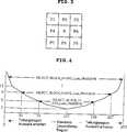
Mit Bezug auf
Das Ermitteln der optimalen Blockanzahl zum Extrahieren oder Identifizieren der Konturen der Ultraschallbilder ist schwierig, wenn das Ultraschallbild zu dunkel ist aufgrund ein zu kleinen mittleren Leuchtdichtewertes AVG_Lum_FRAME oder wenn das Ultraschallbild des analysierten Rasterbildes ist zu hell aufgrund eines zu großen mittleren Leuchtdichtewertes AVG_Lum_FRAME des analysierten Rasterbildes.Determining the optimum block number for extracting or identifying the contours of the ultrasound images is difficult if the ultrasound image is too dark due to too small average luminance value AVG_Lum_FRAME or if the ultrasound image of the analyzed raster image is too bright due to too large average luminance value AVG_Lum_FRAME of the analyzed raster image.
Daher ist es, wenn die optimalen Blöcke des analysierten Rasterbildes und des übrigen Rasterbildes verglichen werden, möglich, die Schallgeschwindigkeit genauer abzuschätzen, indem mehrere optimale Blöcke anstatt nur eines optimalen Blocks jedes Rasterbildes verglichen werden.Therefore, when comparing the optimal blocks of the analyzed raster image and the rest of the raster image, it is possible to more accurately estimate the sound velocity by comparing a plurality of optimal blocks rather than only an optimal block of each raster image.
Jedoch kann es eine lange Zeit dauern, wenn viele optimale Blöcke verglichen werden, um die Schallgeschwindigkeit genau abzuschätzen.However, it can take a long time for many optimal blocks to be compared to accurately estimate the speed of sound.
Daher wird, um die Schallgeschwindigkeit genau und schnell abzuschätzen, die optimale Blockanzahl zum Vergleich mit anderen Rasterbildern bestimmt, indem der Graph der optimalen Blockanzahl in Abhängigkeit von den Leuchtdichtewerten, wie er in
Die optimale Blockanzahl BLOCK_Number wird berechnet, indem der mittlere Leuchtdichtewert AVG_Lum_FRAME des analysierten Rasterbildes mit dem Koeffizienten K, wie in Gleichung 10 gezeigt ist, multipliziert wird.
In Gleichung 10 ist K irgendein durch den Benutzer festgesetzter Koeffizient. K kann, entsprechend der Ultraschalldiagnosevorrichtung, variabel gesetzt werden.In
Im Detail werden, wenn angenommen wird, dass das Ultraschallbild in der Standard-Leuchtdichte-Region, die in
Zum Beispiel werden, wenn zwei optimale Blöcke in der Standard-Leuchtdichte-Region benötigt werden, fünf oder weniger optimale Blöcke benötigt, wenn der mittlere Leuchtdichtewert AVG_Lum_FRAME des. analysierten Rasterbildes im Bereich von 70 bis 185 Stufen liegt und fünf bis neun optimale Blöcke werden benötigt, wenn sich der mittlere Leuchtdichtewert AVG_Lum_FRAME des analysierten Rasterbildes im Bereich von 35 bis 70 Stufen oder von 185 bis 227 Stufen befindet.For example, if two optimal blocks are needed in the standard luminance region, five or less optimal blocks are needed if the average luminance value AVG_Lum_FRAME of the analyzed raster image is in the range of 70 to 185 steps and five to nine optimal blocks are needed when the average luminance value AVG_Lum_FRAME of the analyzed raster image is in the range of 35 to 70 steps or from 185 to 227 steps.
Von daher werden, wenn die optimale Blockanzahl entsprechend des mittleren Leuchtdichtewertes AVG_Lum_FRAME des analysierten Rasterbildes bestimmt wird, so viele optimale Blöcke zum Vergleich mit anderen Rasterbildern wie die optimale Blockanzahl in einer Abfolge von dem größten Wert unter den mittleren Leuchtdichtewerten AVG_Lum_BL jedes Blocks, die bei Schritt S140 berechnet wurden, ausgewählt.Therefore, if the optimal block number is determined according to the average luminance value AVG_Lum_FRAME of the analyzed raster image, then as many optimal blocks as compared with other raster images such as the optimum block number in a sequence of the largest value among the average luminance values AVG_Lum_BL of each block determined at step S140 were selected.
Zum Beispiel werden, wenn die optimale Blockanzahl als drei bestimmt wird, drei Blöcke in einer Abfolge von dem größten Wert unter den mittleren Leuchtdichtewerten AVG_Lum_BL jedes Blocks, die bei Schritt S140 berechnet wurden, an, ausgewählt.For example, when the optimum block number is determined as three, three blocks in a sequence of the largest value among the average luminance values AVG_Lum_BL of each block calculated in step S140 are selected.
Wenn die optimale Blockanzahl entsprechend des mittleren Leuchtdichtewertes AVG_Lum_FRAME analysierten Rasterbilds bei Schritt S150 bestimmt wurde und die entsprechenden optimalen Blöcke ausgewählt wurden, wird das optimale Rasterbild bei dem Auswählen des folgenden optimalen Rasterbilds (S160) ausgewählt, um die Schallgeschwindigkeit des optimalen Rasterbilds als die wirkliche Schallgeschwindigkeit des Ultraschallbildes abzuschätzen.When the optimum block number corresponding to the average luminance value AVG_Lum_FRAME analyzed raster image has been determined at step S150 and the respective optimum blocks have been selected, the optimum raster image in selecting the following optimal raster image (S160) is selected to be the sound velocity of the optimal raster image as the actual sound velocity of the ultrasound image.
Im Detail wird das Rasterbild als das optimale Rasterbild ausgewählt, das den Blöcken, die den maximalen Leuchtdichtewert haben, entspricht, indem die Blöcke, die den bei Schritt S150 als optimale Blöcke ausgewählten entsprechen, für jedes Rasterbild verglichen werden, um die optimalen Blöcke, die den maximalen Leuchtdichtewert haben, zu ermitteln.In detail, the raster image is selected as the optimum raster image corresponding to the blocks having the maximum luminance value by comparing the blocks corresponding to the optimum blocks selected in step S150 for each raster image to the optimum blocks, the have the maximum luminance value to determine.
Wenn bei Schritt S160 das optimale Rasterbild ausgewählt wurde, wird die wirkliche Schallgeschwindigkeit des Objekts, dessen Schallgeschwindigkeit des optimalen Rasterbildes bei Schritt S170 diagnostiziert wird, abgeschätzt und für die Ultraschalldiagnosevorrichtung verwendet.If the optimum raster image has been selected at step S160, the real Sound velocity of the object whose sound velocity of the optimum raster image is diagnosed in step S170, estimated and used for the ultrasonic diagnostic device.
Unterdessen wird die Ultraschalldiagnosevorrichtung, die das Verfahren zur Abschätzung der Schallgeschwindigkeit des Ultraschallbildes wie oben beschrieben benutzt, im Folgenden beschrieben.Meanwhile, the ultrasonic diagnostic apparatus using the method of estimating the velocity of sound of the ultrasonic image as described above will be described below.
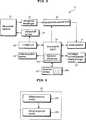
Bezug nehmend auf
Der Ultraschalltastkopf
Im Detail reflektiert, streut und überträgt der Ultraschalltastkopf
Um die Ultraschallwelle in den menschlichen Körper der Testperson durch den Ultraschalltastkopf
Der Ultraschallsender
Der Ultraschallsender
Das Sendesignal ist ein Sendesignal, das die voreingestellte Schallgeschwindigkeit entsprechend der Steuerung des Steuergeräts
Der Ultraschallempfänger
Der Ultraschallempfänger
Die Strahlenfokussiereinheit
Der Bildprozessor
Bezugnehmend auf
Das Bildextraktionsmodul
Zur Zweckdienlichkeit der Erklärung wird in der vorliegenden Erfindung angenommen, dass die Ultraschallbildsignale von 20 Rasterbildern aus 20 Empfangssignalen extrahiert werden und dass das Bilderzeugungsmodul
Die erzeugten Ultraschallbilder von 20 Rasterbildern werden in einer Speichereinheit
Die Schallgeschwindigkeitbestimmungseinheit
Zu diesem Zweck wird die Schallgeschwindigkeitbestimmungseinheit
Ein erster Betriebsmodus, der ein Modus zum Auswählen optimaler Blöcke ist, teilt eines der Ultraschallbilder von mehreren Rasterbildern in eine Mehrzahl von Blöcken, um die Konturen der Ultraschallbilder jedes Blocks zu extrahieren und analysiert die Leuchtdichtewerte jedes Blocks, um die optimale Blockanzahl zu bestimmen, wobei die optimalen Blöcke ausgewählt werden.A first mode of operation, which is a mode for selecting optimal blocks, divides one of the ultrasound images of a plurality of raster images into a plurality of blocks to extract the contours of the ultrasound images of each block and analyzes the luminance values of each block to determine the optimum block number the optimal blocks are selected.
Der zweite Betriebsmodus, der ein Modus zum Auswählen des optimalen Rasterbildes ist, verwendet die optimale Blockposition, die von dem ersten Betriebsmodus ausgewählt wurde, als die gleiche optimale Blockposition für das verbleibende Rasterbild, um die mittleren Leuchtdichtewerte der optimalen Blöcke jedes Rasterbildes zu vergleichen, wobei schließlich das Rasterbild als optimales Rasterbild ausgewählt wird, das den optimalen Blöcken entspricht, die die maximalen Leuchtdichtewerte haben.The second mode of operation, which is a mode for selecting the optimum raster image, uses the optimal block position selected from the first mode of operation as the same optimal block position for the remaining raster image to compare the average luminance values of the optimal blocks of each raster image Finally, the raster image is selected as the optimal raster image corresponding to the optimum blocks having the maximum luminance values.
Die Schallgeschwindigkeitsbestimmungseinheit
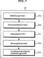
Bezugnehmend auf
Zuerst wird im Folgenden der Betrieb der oben genannten Komponenten im ersten Betriebsmodus beschrieben werden.First, the operation of the above components in the first operation mode will be described below.
Das Bildteilungsmodul
Während des Beschneidens kann der vorbestimmte Bereich so ausgewählt werden, dass relevante Bilder manuell vom Benutzer beschnitten werden oder dass die Bilder eines bestimmten Bereichs automatisch beschnitten werden.During trimming, the predetermined area may be selected such that relevant images are cropped manually by the user or that the images of a particular area are automatically trimmed.
Danach werden die Ultraschallbilder von 20 Rasterbildern, von denen jedes beschnitten ist, in eine Vielzahl von Blöcken (zum Beispiel N × M) für jedes Rasterbild aufgeteilt.Thereafter, the ultrasound images of 20 raster images, each of which is cropped, are divided into a plurality of blocks (for example, N x M) for each raster image.
Das Konturextraktionsmodul
Das Bildanalysemodul
Die mittleren Leuchtdichtewerte AVG_Lum_BL werden berechnet, indem die Gesamtsumme der Pixelleuchtdichte jedes Blocks durch die gesamte Pixelanzahl jedes Blocks dividiert wird, und wird in einer Wertetabelle
Dadurch können die mittleren Leuchtdichtewerte AVG_Lum_BL jedes Blocks in aufsteigender oder absteigender Reihenfolge extrahiert werden.Thereby, the average luminance values AVG_Lum_BL of each block can be extracted in ascending or descending order.
Zusätzlich wird der mittlere Leuchtdichtewert AVG_Lum_FRAME des analysierten Rasterbildes berechnet, indem die Gesamtsumme der mittleren Leuchtdichtewerte AVG_Lum_BL jedes Blocks des analysierten Rasterbildes durch die Gesamtanzahl der Blöcke des analysierten Rasterbildes geteilt wird, und ebenso in der Wertetabelle
Das Bildvergleichsmodul
Wenn die optimale Blockanzahl bestimmt ist, werden so viele optimale Blöcke wie die ermittelte optimale Blockanzahl in einer Reihe von dem größten Wert unter den in dem Bildanalysemodul
Wenn die optimalen Blöcke des analysierten Rasterbildes durch das oben genannte Verfahren ausgewählt werden, werden die Blöcke, die den maximalen Leuchtdichtewert haben, extrahiert, indem die optimalen Blöcke an der gleichen Position auch im Fall des übrigen Rasterbildes verglichen werden.When the optimum blocks of the analyzed raster image are selected by the above-mentioned method, the blocks having the maximum luminance value are extracted by comparing the optimum blocks at the same position also in the case of the remaining raster image.
Das Schallgeschwindigkeitsbestimmungsmodul
Wiederum auf
Die Datenausgabeeinheit
Das Interface
Zwei Steuersignale werden von dem Steuergerät
Eines ist ein Steuersignal, um dem Ultraschallsender
Das Steuergerät
Das Steuergerät
Das Steuergerät
Zusätzlich führt das Steuergerät
Danach führt das Steuergerät
Wie oben beschrieben, vergleicht und liefert das Verfahren zur Abschätzung der Schallgeschwindigkeit von Ultraschallbildern sowie die Ultraschalldiagnosevorrichtung entsprechend einer beispielhaften Ausführungsform der vorliegenden Erfindung, die dieses Verfahren verwendet, nur die vorbestimmten optimalen Blöcke in einer Reihe vom größten Leuchtdichtewert an, ohne alle Ultraschallbilder zu vergleichen, um die wirkliche Schallgeschwindigkeit der Ultraschallbilder abzuschätzen, wodurch es möglich macht, die Schallgeschwindigkeit der Ultraschallbilder in Echtzeit abzuschätzen.As described above, the ultrasonic velocity estimating method and the ultrasonic diagnostic apparatus according to an exemplary embodiment of the present invention using this method compare and supply only the predetermined optimum blocks in a row of the largest luminance value without comparing all the ultrasonic images. to estimate the true sound velocity of the ultrasound images, thereby making it possible to estimate the sound velocity of the ultrasound images in real time.
Die vorliegende Erfindung kann die Schallgeschwindigkeit schneller und genauer abschätzen, indem die Ultraschallbilder aufgeteilt und die Analysebereiche in den gesamten Ultraschallbildern definiert werden.The present invention can more quickly and accurately estimate the speed of sound by splitting the ultrasound images and defining the analysis areas throughout the ultrasound images.
Zusätzlich kann die vorliegende Erfindung höher aufgelöste Ultraschallbilder erhalten, indem die abgeschätzte Schallgeschwindigkeit für die Ultraschalldiagnosevorrichtung in Echtzeit verwendet wird.In addition, the present invention can obtain higher resolution ultrasound images by using the estimated sound velocity for the ultrasound diagnostic device in real time.
Obwohl die Ausführungsformen der vorliegenden Erfindung zu Erläuterungszwecken offenbart worden sind, wird der Fachmann erkennen, dass verschiedene Abwandlungen, Erweiterungen und Ersetzungen möglich sind, ohne vom Inhalt und Gedanken der Erfindung abzuweichen. Entsprechend sollten solche Abwandlungen, Erweiterungen und Ersetzungen ebenfalls als in den Bereich der vorliegenden Erfindung fallend angesehen werden. Although the embodiments of the present invention have been disclosed for illustrative purposes, those skilled in the art will recognize that various modifications, additions and substitutions are possible, without departing from the spirit and content of the invention. Accordingly, such modifications, extensions and substitutions should also be considered as falling within the scope of the present invention.
ZITATE ENTHALTEN IN DER BESCHREIBUNG QUOTES INCLUDE IN THE DESCRIPTION
Diese Liste der vom Anmelder aufgeführten Dokumente wurde automatisiert erzeugt und ist ausschließlich zur besseren Information des Lesers aufgenommen. Die Liste ist nicht Bestandteil der deutschen Patent- bzw. Gebrauchsmusteranmeldung. Das DPMA übernimmt keinerlei Haftung für etwaige Fehler oder Auslassungen.This list of the documents listed by the applicant has been generated automatically and is included solely for the better information of the reader. The list is not part of the German patent or utility model application. The DPMA assumes no liability for any errors or omissions.
Zitierte PatentliteraturCited patent literature
- KR 10-2010-0075639[0001]KR 10-2010-0075639[0001]
Claims (11)
Translated fromGermanApplications Claiming Priority (2)
| Application Number | Priority Date | Filing Date | Title |
|---|---|---|---|
| KR10-2010-0075639 | 2010-08-05 | ||
| KR1020100075639AKR101140934B1 (en) | 2010-08-05 | 2010-08-05 | Method for Estimating Acoustic Velocity of Ultrasonic Image and Ultrasonic Diagnosis Apparatus using the same |
Publications (1)
| Publication Number | Publication Date |
|---|---|
| DE102010051620A1true DE102010051620A1 (en) | 2012-02-09 |
Family
ID=45495098
Family Applications (1)
| Application Number | Title | Priority Date | Filing Date |
|---|---|---|---|
| DE102010051620ACeasedDE102010051620A1 (en) | 2010-08-05 | 2010-11-16 | A method of estimating the sound velocity of an ultrasound image and an ultrasound diagnostic apparatus using the same |
Country Status (3)
| Country | Link |
|---|---|
| US (1) | US8702608B2 (en) |
| KR (1) | KR101140934B1 (en) |
| DE (1) | DE102010051620A1 (en) |
Families Citing this family (22)
| Publication number | Priority date | Publication date | Assignee | Title |
|---|---|---|---|---|
| US10226234B2 (en) | 2011-12-01 | 2019-03-12 | Maui Imaging, Inc. | Motion detection using ping-based and multiple aperture doppler ultrasound |
| US9788813B2 (en) | 2010-10-13 | 2017-10-17 | Maui Imaging, Inc. | Multiple aperture probe internal apparatus and cable assemblies |
| US9282945B2 (en) | 2009-04-14 | 2016-03-15 | Maui Imaging, Inc. | Calibration of ultrasound probes |
| JP6274724B2 (en) | 2010-02-18 | 2018-02-07 | マウイ イマギング,インコーポレーテッド | Point source transmission and sound velocity correction using multi-aperture ultrasound imaging |
| KR101906838B1 (en) | 2010-10-13 | 2018-10-11 | 마우이 이미징, 인코포레이티드 | Concave ultrasound transducers and 3d arrays |
| JP2015503404A (en) | 2011-12-29 | 2015-02-02 | マウイ イマギング,インコーポレーテッド | Arbitrary path M-mode ultrasound imaging |
| JP6438769B2 (en) | 2012-02-21 | 2018-12-19 | マウイ イマギング,インコーポレーテッド | Determination of material hardness using multiple aperture ultrasound. |
| WO2013148673A1 (en) | 2012-03-26 | 2013-10-03 | Maui Imaging, Inc. | Systems and methods for improving ultrasound image quality by applying weighting factors |
| JP6270843B2 (en) | 2012-08-10 | 2018-01-31 | マウイ イマギング,インコーポレーテッド | Calibration of multiple aperture ultrasonic probes |
| WO2014031642A1 (en) | 2012-08-21 | 2014-02-27 | Maui Imaging, Inc. | Ultrasound imaging system memory architecture |
| US20140064513A1 (en) | 2012-09-06 | 2014-03-06 | MUSIC Group IP Ltd. | System and method for remotely controlling audio equipment |
| JP5836241B2 (en)* | 2012-09-28 | 2015-12-24 | 富士フイルム株式会社 | Ultrasonic inspection apparatus, signal processing method and program for ultrasonic inspection apparatus |
| JP5829198B2 (en)* | 2012-09-27 | 2015-12-09 | 富士フイルム株式会社 | Ultrasonic inspection apparatus, signal processing method and program for ultrasonic inspection apparatus |
| JP5841034B2 (en)* | 2012-09-27 | 2016-01-06 | 富士フイルム株式会社 | Ultrasonic diagnostic apparatus, ultrasonic image generation method and program |
| WO2014160291A1 (en) | 2013-03-13 | 2014-10-02 | Maui Imaging, Inc. | Alignment of ultrasound transducer arrays and multiple aperture probe assembly |
| US9883848B2 (en) | 2013-09-13 | 2018-02-06 | Maui Imaging, Inc. | Ultrasound imaging using apparent point-source transmit transducer |
| CN106794007B (en) | 2014-08-18 | 2021-03-09 | 毛伊图像公司 | Network-based ultrasound imaging system |
| US10197312B2 (en) | 2014-08-26 | 2019-02-05 | Mahle International Gmbh | Heat exchanger with reduced length distributor tube |
| KR102681141B1 (en) | 2015-03-30 | 2024-07-02 | 마우이 이미징, 인코포레이티드 | Ultrasonic imaging systems and methods for detecting object motion |
| CN108778530B (en) | 2016-01-27 | 2021-07-27 | 毛伊图像公司 | Ultrasound imaging with sparse array detectors |
| KR102074187B1 (en)* | 2018-04-19 | 2020-02-06 | 재단법인 대구경북첨단의료산업진흥재단 | Device for forming image in photoacoustic system and method thereof |
| EP3632330B1 (en)* | 2018-10-04 | 2022-08-24 | SuperSonic Imagine | Method for determining a speed of sound in a medium, an ultrasound imaging system implementing said method |
Citations (3)
| Publication number | Priority date | Publication date | Assignee | Title |
|---|---|---|---|---|
| EP1262148A1 (en)* | 2000-03-10 | 2002-12-04 | Hitachi Medical Corporation | Ultrasonic imaging device |
| US20060235302A1 (en)* | 2004-09-20 | 2006-10-19 | Jeffrey Grossman | Systems and methods for ultrasound imaging |
| KR20100075639A (en) | 2007-10-15 | 2010-07-02 | 센토코 오르토 바이오테크 인코포레이티드 | Human anti-amyloid antibodies, compositions, methods and uses |
Family Cites Families (7)
| Publication number | Priority date | Publication date | Assignee | Title |
|---|---|---|---|---|
| US5638820A (en)* | 1996-06-25 | 1997-06-17 | Siemens Medical Systems, Inc. | Ultrasound system for estimating the speed of sound in body tissue |
| KR100490395B1 (en)* | 2001-10-29 | 2005-05-17 | 삼성전자주식회사 | Motion vector estimation method and apparatus thereof |
| JP2004141514A (en)* | 2002-10-28 | 2004-05-20 | Toshiba Corp | Image processing device and ultrasonic diagnostic device |
| KR100869497B1 (en)* | 2005-07-01 | 2008-11-21 | 주식회사 메디슨 | Hierarchical Motion Estimation Method and Ultrasonic Imaging Applied to It |
| KR100875203B1 (en)* | 2005-12-28 | 2008-12-19 | 주식회사 메디슨 | Acquisition Method of Ultrasound |
| KR100948045B1 (en)* | 2007-03-20 | 2010-03-19 | 주식회사 메디슨 | Ultrasound System and Method for Forming Ultrasound Images |
| EP1974672B9 (en)* | 2007-03-28 | 2014-04-16 | Kabushiki Kaisha Toshiba | Ultrasonic imaging apparatus and ultrasonic velocity optimization method |
- 2010
- 2010-08-05KRKR1020100075639Apatent/KR101140934B1/ennot_activeExpired - Fee Related
- 2010-11-16DEDE102010051620Apatent/DE102010051620A1/ennot_activeCeased
- 2010-11-19USUS12/950,829patent/US8702608B2/ennot_activeExpired - Fee Related
Patent Citations (3)
| Publication number | Priority date | Publication date | Assignee | Title |
|---|---|---|---|---|
| EP1262148A1 (en)* | 2000-03-10 | 2002-12-04 | Hitachi Medical Corporation | Ultrasonic imaging device |
| US20060235302A1 (en)* | 2004-09-20 | 2006-10-19 | Jeffrey Grossman | Systems and methods for ultrasound imaging |
| KR20100075639A (en) | 2007-10-15 | 2010-07-02 | 센토코 오르토 바이오테크 인코포레이티드 | Human anti-amyloid antibodies, compositions, methods and uses |
Also Published As
| Publication number | Publication date |
|---|---|
| US20120035482A1 (en) | 2012-02-09 |
| KR101140934B1 (en) | 2012-05-03 |
| KR20120013585A (en) | 2012-02-15 |
| US8702608B2 (en) | 2014-04-22 |
Similar Documents
| Publication | Publication Date | Title |
|---|---|---|
| DE102010051620A1 (en) | A method of estimating the sound velocity of an ultrasound image and an ultrasound diagnostic apparatus using the same | |
| DE102012108353B4 (en) | CLASSIFICATION PREPROCESSING IN MEDICAL ULTRASONIC SHEAR WAVE IMAGING | |
| DE3686401T2 (en) | PRESENTATION OF STREAM LINES IN INHOMOGENIC MEDIA. | |
| DE19819893B4 (en) | Method and apparatus for improving resolution and sensitivity in color flow ultrasound imaging | |
| DE102009023896B4 (en) | Apparatus and method for detecting a plant | |
| DE60028952T2 (en) | METHOD AND DEVICE FOR GENERATING PICTURES THROUGH THE USE OF SHEARS | |
| DE19819832B4 (en) | Method for improving the segmentation in a three-dimensional ultrasound imaging | |
| DE19828947B4 (en) | System and method for three-dimensional (3-D) ultrasound imaging and motion estimation | |
| DE69736549T2 (en) | SYSTEM, METHOD AND CONVERTER FOR ORIENTING MULTIPLE ULTRASOUND IMAGES | |
| DE69807575T2 (en) | Ultrasound imaging system with Doppler tracking of tissue movement | |
| DE102016100367B4 (en) | Sparse tracking in sonic beam intensity pulse imaging | |
| EP3462412B1 (en) | Determining a two-dimensional mammography data set | |
| DE102017211895A1 (en) | Tissue characterization in medical diagnostic ultrasound | |
| DE19910771A1 (en) | Method of tracking a scanning plane motion for three-dimensional freehand ultrasonic scanning of the human anatomy using adaptive spot correlation | |
| EP1324701A1 (en) | Ultrasonic tomograph | |
| DE10128206B4 (en) | Three-dimensional ultrasound imaging using a movable probe | |
| DE10317384A1 (en) | Computed Tomography | |
| DE102005016944A1 (en) | Method and device for detecting anatomical structures | |
| DE102006027992A1 (en) | Image frames` movement correcting method for use in spatial-compound-ultrasonic imaging, involves updating prior movement estimated value with estimated movement, and correcting image frame and preceding image frame using updated value | |
| DE10243152A1 (en) | Ultrasound diagnostic method and device for imaging from multiple 2D sections | |
| DE102016101552A1 (en) | Method for creating an environment map for a self-moving processing device | |
| DE102015116500A1 (en) | Suppression of shadows in ultrasound imaging | |
| DE102016116658A1 (en) | SPARKLEAR FACT RECOGNITION IN ULTRASONIC COLOR FLOW | |
| DE102008046019A1 (en) | Profit optimization of volume images for medical diagnostic ultrasound imaging | |
| WO2014139504A1 (en) | Apparatus for volumetrically measuring an object in the body of an animal for slaughter |
Legal Events
| Date | Code | Title | Description |
|---|---|---|---|
| R016 | Response to examination communication | ||
| R016 | Response to examination communication | ||
| R002 | Refusal decision in examination/registration proceedings | ||
| R003 | Refusal decision now final | ||
| R003 | Refusal decision now final | Effective date:20140703 |