DE102010049759A1 - Device for manual retraction of muscle or for lifting another organ, has spatula device for rear driving of muscle or organ, handle and joint provided between proximal end of spatula device and handle - Google Patents
Device for manual retraction of muscle or for lifting another organ, has spatula device for rear driving of muscle or organ, handle and joint provided between proximal end of spatula device and handleDownload PDFInfo
- Publication number
- DE102010049759A1 DE102010049759A1DE102010049759ADE102010049759ADE102010049759A1DE 102010049759 A1DE102010049759 A1DE 102010049759A1DE 102010049759 ADE102010049759 ADE 102010049759ADE 102010049759 ADE102010049759 ADE 102010049759ADE 102010049759 A1DE102010049759 A1DE 102010049759A1
- Authority
- DE
- Germany
- Prior art keywords
- handle
- spatula
- contraption
- joint
- muscle
- Prior art date
- Legal status (The legal status is an assumption and is not a legal conclusion. Google has not performed a legal analysis and makes no representation as to the accuracy of the status listed.)
- Pending
Links
Images

Classifications
- A—HUMAN NECESSITIES
- A61—MEDICAL OR VETERINARY SCIENCE; HYGIENE
- A61B—DIAGNOSIS; SURGERY; IDENTIFICATION
- A61B17/00—Surgical instruments, devices or methods
- A61B17/02—Surgical instruments, devices or methods for holding wounds open, e.g. retractors; Tractors
- A—HUMAN NECESSITIES
- A61—MEDICAL OR VETERINARY SCIENCE; HYGIENE
- A61B—DIAGNOSIS; SURGERY; IDENTIFICATION
- A61B90/00—Instruments, implements or accessories specially adapted for surgery or diagnosis and not covered by any of the groups A61B1/00 - A61B50/00, e.g. for luxation treatment or for protecting wound edges
- A61B90/30—Devices for illuminating a surgical field, the devices having an interrelation with other surgical devices or with a surgical procedure
Landscapes
- Health & Medical Sciences (AREA)
- Surgery (AREA)
- Life Sciences & Earth Sciences (AREA)
- Heart & Thoracic Surgery (AREA)
- Engineering & Computer Science (AREA)
- Biomedical Technology (AREA)
- Nuclear Medicine, Radiotherapy & Molecular Imaging (AREA)
- Medical Informatics (AREA)
- Molecular Biology (AREA)
- Animal Behavior & Ethology (AREA)
- General Health & Medical Sciences (AREA)
- Public Health (AREA)
- Veterinary Medicine (AREA)
- Pathology (AREA)
- Oral & Maxillofacial Surgery (AREA)
- Endoscopes (AREA)
Abstract
Description
Translated fromGermanDie vorliegende Erfindung bezieht sich auf eine Vorrichtung zur manuellen Retraktion eines Muskels, insbesondere des großen Rückenmuskels, oder zum Abheben eines anderen Organs.The present invention relates to a device for manual retraction of a muscle, in particular of the large dorsal muscle, or for lifting of another organ.
Ein Ansatz zur Brustrekonstruktion nach Mastektomie umfasst die Verwendung eines Lappen des großen Rückenmuskels (Musculus latissimus dorsi) als autologes Implantat. Im Rahmen eines derartigen Eingriffs muss der große Rückenmuskel abgehoben werden. Dazu wird der Rückenmuskel mit eine Spateleinrichtung hinterfahren. Am proximalen Ende der Spateleinrichtung ist ein Handgriff zur Handhabung der Spateleinrichtung vorgesehen. Während der Operation kann es erforderlich sein, dass der Operateur den Retraktor in situ an medizinisches Personal übergibt, das an der gegenüberliegenden Seite des Operationstisches steht. Dabei stellt sich in vielen Fällen heraus, dass der beschriebene Retraktor vom empfangenden medizinischen Personal nicht ohne Weiteres mit einer entspannten Körper- und Hand-Haltung gehalten werden kann.One approach to breast reconstruction following mastectomy involves the use of a flap of the large dorsal muscle (latissimus dorsi muscle) as an autologous implant. In the context of such an intervention, the large back muscle must be lifted. For this purpose, the back muscle is traced with a spatula device. At the proximal end of the spatula device, a handle for handling the spatula device is provided. During surgery, the surgeon may be required to deliver the retractor in situ to medical personnel standing on the opposite side of the operating table. It turns out in many cases that the retractor described by the receiving medical staff can not be easily held with a relaxed body and hand posture.
Eine Aufgabe der vorliegenden Erfindung besteht darin, eine verbesserte Vorrichtung zur manuellen Retraktion eines Muskels oder zum Abheben eines anderen Organs zu schaffen.An object of the present invention is to provide an improved device for manual retraction of a muscle or for lifting another organ.
Diese Aufgabe wird durch die Gegenstände der unabhängigen Ansprüche gelöst.This object is solved by the subject matters of the independent claims.
Weiterbildungen sind in den abhängigen Ansprüchen angegeben.Further developments are specified in the dependent claims.
Eine Vorrichtung zur manuellen Retraktion eines Muskels oder zum Abheben eines anderen Organs umfasst eine Spateleinrichtung zum Hinterfahren des Muskels bzw. des Organs, einen Handgriff und ein Gelenk zwischen dem proximalen Ende der Spateleinrichtung und dem Handgriff.A device for manual retraction of a muscle or for lifting of another organ comprises a spatula device for trailing the muscle or the organ, a handle and a joint between the proximal end of the spatula device and the handle.
Der Handgriff ist insbesondere Bestandteil einer Handhabungseinrichtung, wobei die Handhabungseinrichtung und di Spateleinrichtung durch das Gelenk gelenkig miteinander verbunden sind. Das Gelenk zwischen dem Handgriff und der Spateleinrichtung ermöglicht eine Anpassung der Ausrichtung des Handgriffs relativ zur Spateleinrichtung, bei der ein entspanntes und ermüdungsarmes Halten der Vorrichtung durch medizinisches Personal möglich ist. Insbesondere kann medizinisches Personal beiderseits eines Operationstisches den Handgriff relativ zu der Spateleinrichtung jeweils für sich optimal einstellen, oder es kann eine Einstellung gefunden werden, die für medizinisches Personal beiderseits des Operationstisches günstig ist. Damit ermöglicht die Vorrichtung mit dem Gelenk zwischen dem Handgriff und der Spateleinrichtung ein ermüdungsarmes und in der Folge präzises und fehlerarmes Arbeiten.The handle is in particular part of a handling device, wherein the handling device and the spatula device are hinged together by the joint. The joint between the handle and the spatula device allows adjustment of the orientation of the handle relative to the spatula device, in which a relaxed and fatigue-poor holding of the device by medical personnel is possible. In particular, medical personnel on either side of a surgical table can optimally adjust the handle relative to the spatula device individually or a setting can be found which is favorable for medical personnel on both sides of the surgical table. Thus, the device allows with the joint between the handle and the spatula a fatigue-poor and consequently precise and low-error working.
Eine Vorrichtung, wie sie hier beschrieben ist, kann ferner eine Lichtleiteinrichtung umfassen, die eine Kupplung für ein Lichtleitkabel mit einer Lichtaustrittsfläche am distalen Ende der Spateleinrichtung koppelt.A device as described herein may further comprise a light guide coupling a coupling for a light pipe to a light exit surface at the distal end of the spatula device.
Die Lichtleiteinrichtung ermöglicht eine Beleuchtung des Raums am distalen Ende, insbesondere des Raums distal des distalen Endes der Spateleinrichtung. Dazu kann von einer Lichtquelle erzeugtes Beleuchtungslicht mittels eines Lichtleitkabels und über die Kupplung in die Lichtleiteinrichtung eingekoppelt werden.The light-conducting device makes it possible to illuminate the space at the distal end, in particular the space distal to the distal end of the spatula device. For this purpose, illumination light generated by a light source can be coupled into the light-conducting device by means of a light-conducting cable and via the coupling.
Die Beleuchtung des Raums distal des distalen Endes der Spateleinrichtung macht es für das medizinische Personal, insbesondere für den Operateur, einfacher, den Muskel bzw. das Organ bei visueller Kontrolle mittels der Spateleinrichtung zu hinterfahren. Durch einen oder mehrere Lichtaustritte am distalen Ende der Spateleinrichtung kann Beleuchtungslicht gezielt dort abgestrahlt werden, wo es benötigt wird. Die Verteilung des Beleuchtungslichts ist damit wesentlich günstiger als beispielsweise bei Beleuchtung durch eine Operationslampe von außen.The illumination of the space distal of the distal end of the spatula device makes it easier for the medical staff, in particular for the surgeon, to drive the muscle or the organ under visual control by means of the spatula device. By one or more light exits at the distal end of the spatula illumination light can be selectively emitted where it is needed. The distribution of the illumination light is thus much cheaper than, for example, when illuminated by an operating lamp from the outside.
Die Kupplung kann starr mit der Spateleinrichtung verbunden sein.The coupling may be rigidly connected to the spatula device.
Eine starre Anordnung der Kupplung an der Spateleinrichtung ermöglicht eine Ausbildung der Lichtleiteinrichtung, bei der die Lichtleiteinrichtung auch beim Verändern der Orientierung des Handgriffs relativ zur Spateleinrichtung nicht verformt oder bewegt wird. Die Wahrscheinlichkeit eines Defekts an der Lichtleiteinrichtung, beispielsweise eines Faserbruchs, kann dadurch sehr deutlich reduziert werden.A rigid arrangement of the coupling on the spatula device allows a design of the light-conducting device, in which the light-guiding device is not deformed or moved relative to the spatula device even when the orientation of the handle is changed. The probability of a defect in the light-guiding device, for example a fiber breakage, can thereby be reduced significantly.
Ferner ist die hermetische Abdichtung der Lichtleiteinrichtung gegenüber Gasen oder Flüssigkeiten deutlich einfacher realisierbar, wenn die Kupplung ohne einen flexiblen Abschnitt oder ein Gelenk starr mit der Spateleinrichtung verbunden ist. Die Lichtleiteinrichtung kann in diesem Fall in einem geschlossenen, insbesondere metallischen Mantel angeordnet sein, der die Lichtleiteinrichtung von der Kupplung bis zum Lichtaustritt vollständig umschließt und gegenüber Umwelteinflüssen abschirmt. Dieser Mantel ist insbesondere spatelförmig und bildet einen integralen Bestandteil der Spateleinrichtung.Furthermore, the hermetic sealing of the light-conducting device with respect to gases or liquids is much easier to implement if the coupling is rigidly connected to the spatula device without a flexible section or joint. The light-conducting device can be arranged in this case in a closed, in particular metallic sheath, which completely encloses the light-conducting device from the coupling to the light exit and shields it against environmental influences. This jacket is in particular spatulate and forms an integral part of the spatula device.
Bei einer Vorrichtung mit Lichtleiteinrichtung, wie sie hier beschrieben ist, kann der Handgriff einen Kanal zur Aufnahme eines Lichtleitkabels umfassen.In a device with light guide device, as described here, the handle may comprise a channel for receiving a light guide cable.
Das Lichtleitkabel koppelt insbesondere die bereits erwähnte externe Lichtquelle über die Kupplung mit der Lichtleiteinrichtung der Vorrichtung. Die Anordnung des Lichtleitkabels in einem Kanal im Handgriff ermöglicht gleichzeitig eine Führung des Lichtleitkabels und seine Wegführung aus dem Operationsgebiet. Das im Kanal des Handgriffs angeordnete Lichtleitkabel folgt automatisch jeder Bewegung der Vorrichtung. Auf seinen Verlauf im Operationsgebiet oder nahe dem Operationsgebiet muss in diesem Fall in der Regel nicht weiter geachtet werden. Dies vereinfacht die Handhabung der Vorrichtung, entlastet das medizinische Personal und unterstützt ein ermüdungsarmes, präzises und fehlerarmes Arbeiten.The light guide cable in particular couples the already mentioned external light source via the Coupling with the light-conducting device of the device. The arrangement of the optical fiber cable in a channel in the handle at the same time allows guidance of the optical fiber cable and its routing out of the operating area. The arranged in the channel of the handle fiber optic cable automatically follows every movement of the device. Its course in the operating area or near the surgical area in this case usually does not need to be paid attention. This simplifies the handling of the device, relieves the medical staff and supports fatigue-free, precise and low-error work.
Die Vorrichtung ist insbesondere dazu ausgebildet, dass beim Schwenken des Handgriffs um das Gelenk ein mit der Kupplung verbundenes und durch den Kanal geführtes Lichtleitkabel im Kanal verbleibt und distal der Kupplung elastisch verformt wird.The device is in particular designed so that, when the handle is pivoted about the joint, a light guide cable connected to the coupling and guided through the channel remains in the channel and is deformed elastically distally of the coupling.
Ein elastisches Verformen des Lichtleitkabels kann zu einem Defekt, insbesondere zu einem Faserbruch, führen, ebenso wie gegebenenfalls ein elastisches Verformen der Lichtleiteinrichtung der Vorrichtung zu einem Defekt führen kann. Wenn die Vorrichtung jedoch dazu ausgebildet ist, beim Schwenken des Handgriffs das mit der Kupplung verbundene Lichtleitkabel elastisch zu verformen, während insbesondere die Lichtleiteinrichtung und die Kupplung starr angeordnet sind, wird das Risiko eines Defekts sehr weitgehend beim Lichtleitkabel konzentriert. Das Lichtleitkabel kann ohne Weiteres und verhältnismäßig kostengünstig austauschbar sein. Im Gegensatz dazu ist bei einem Defekt an der Lichtleiteinrichtung der Vorrichtung ein vollständiger Austausch der Vorrichtung bzw. deren Reparatur erfordern, was mit deutlich höherem Aufwand verbunden ist.An elastic deformation of the optical fiber cable can lead to a defect, in particular to a fiber break, as well as possibly an elastic deformation of the optical fiber device of the device can lead to a defect. However, if the device is designed to elastically deform the light guide cable connected to the coupling during pivoting of the handle, in particular while the light guide device and the coupling are rigidly arranged, the risk of a defect is very largely concentrated in the light guide cable. The fiber optic cable can be readily and inexpensively exchangeable. In contrast, in the case of a defect in the light-conducting device, the device requires a complete replacement of the device or its repair, which is associated with a significantly higher outlay.
Eine Vorrichtung, wie sie hier beschrieben ist, kann ferner eine Schraubverbindung zwischen dem Handgriff und dem Gelenk umfassen.A device as described herein may further comprise a threaded connection between the handle and the hinge.
Eine Schraubverbindung zwischen Handgriff und Gelenk ermöglicht einen einfachen Austausch des Handgriffs, beispielsweise zur Anpassung der Vorrichtung an die Hand oder die Greifgewohnheiten medizinischen Personals. Ferner kann eine Trennbarkeit zwischen dem Handgriff und dem Gelenk eine Sterilisation der Vorrichtung vereinfachen. Insbesondere wenn der Handgriff, wie oben beschrieben, einen Kanal zur Aufnahme eines Lichtleitkabels umfasst, kann die leicht lösbare Schraubverbindung zwischen dem Handgriff und dem Gelenk eine Montage und Demontage eines Lichtleitkabels an der Kupplung vereinfachen.A screw connection between the handle and the joint allows a simple exchange of the handle, for example, to adapt the device to the hand or the gripping habits of medical personnel. Further, separability between the handle and the joint may facilitate sterilization of the device. In particular, when the handle, as described above, includes a channel for receiving a fiber optic cable, the easily detachable threaded connection between the handle and the hinge may facilitate assembly and disassembly of a fiber optic cable to the coupling.
Die Schraubverbindung kann eine Gewinde an einer Gewindehülse umfassen, wobei die Gewindehülse mit dem Gelenk dauerhaft verbunden ist, und wobei die Gewindehülse einen Schlitz aufweist, durch den ein Lichtleitkabel in einer bezogen auf die Achse der Schraubverbindung radialen Bewegung in das Lumen der Gewindehülse eingelegt werden kann.The threaded connection may comprise a thread on a threaded sleeve, wherein the threaded sleeve is permanently connected to the joint, and wherein the threaded sleeve has a slot through which a Lichtleitkabel in relation to the axis of the screw radial movement in the lumen of the threaded sleeve can be inserted ,
Der oben genannte Vorteil der Schraubverbindung, die Montage und Demontage eines Lichtleitkabels zu vereinfachen, gilt insbesondere bei der beschriebenen Ausführung der Gewindehülse mit einem Schlitz. Das Lichtleitkabel kann in beliebiger Reihenfolge in das Lumen der Gewindehülse eingelegt und mit der Kupplung der Vorrichtung verbunden werden, wenn der Handgriff erst anschließend mit der Gewindehülse verschraubt wird. Dazu weisen insbesondere die Gewindehülse ein Außengewinde und der Handgriff ein Innengewinde auf.The above-mentioned advantage of the screw connection to simplify the assembly and disassembly of a fiber optic cable, in particular in the described embodiment of the threaded sleeve with a slot. The light guide can be inserted in any order in the lumen of the threaded sleeve and connected to the coupling of the device when the handle is then screwed to the threaded sleeve. For this purpose, in particular the threaded sleeve on an external thread and the handle on an internal thread.
Bei einer Vorrichtung, wie sie hier beschrieben ist, kann der Handgriff Teil einer Handhabungseinrichtung sein, die zwischen dem Handgriff und dem Gelenk tailliert ist.In a device as described herein, the handle may be part of a handling device that is waisted between the handle and the hinge.
Insbesondere weist die Handhabungseinrichtung zwischen dem Handgriff und dem Gelenk einen taillierten Holm oder mehrere Holme, deren gemeinsame äußere Kontur tailliert ist, auf. Die Taillierung ist insbesondere in der Nähe des Orts vorgesehen, an dem eine Kupplung eines Lichtleitkabels zur Montage an oder zur Demontage von der Kupplung der Vorrichtung zu greifen ist. Die Taillierung kann dadurch die Montage oder Demontage eines Lichtleitkabels an der Kupplung der Vorrichtung vereinfachen, indem sie den manuellen Zugriff auf die Kupplung des Lichtleitkabels und/oder die Kupplung an der Vorrichtung vereinfacht.In particular, the handling device between the handle and the joint has a waisted spar or a plurality of spars whose common outer contour is waisted on. The waisting is provided in particular in the vicinity of the location at which a coupling of a light guide cable for mounting on or for disassembly of the coupling of the device is to grip. The waist can thereby facilitate the assembly or disassembly of a fiber optic cable to the coupling of the device by facilitating manual access to the coupling of the fiber optic cable and / or the coupling to the device.
Eine Vorrichtung, wie sie hier beschrieben ist, kann eine Arretierung zum Festlegen des Gelenks umfassen.A device as described herein may include a lock for securing the hinge.
Die Arretierung ist insbesondere zur Arretierung der Handhabungseinrichtung und der Spateleinrichtung in einer oder mehreren vorbestimmten relativen Orientierungen ausgebildet. Beispielsweise ist die Arretierung ausgebildet, um das Gelenk in mehreren Winkelpositionen mit gleichen oder unterschiedlichen Winkelabständen zu arretieren. Alternativ kann die Arretierung ausgebildet sein, um die Handhabungseinrichtung und die Spateleinrichtung in jeder beliebigen relativen Orientierung zu fixieren. Die Arretierung kann durch Druck auf eine oder durch gleichzeitigen Druck auf mehrere Entriegelungsknöpfe entriegelbar sein.The lock is designed in particular for locking the handling device and the spatula device in one or more predetermined relative orientations. For example, the lock is designed to lock the joint in several angular positions with equal or different angular intervals. Alternatively, the detent may be configured to fix the handling device and the spatula device in any relative orientation. The lock can be unlocked by pressure on one or by simultaneous pressure on several release buttons.
Insbesondere eine alternative Festlegung des Gelenks in mehreren vorbestimmten relativen Orientierungen von Handhabungseinrichtung und Spateleinrichtung kann die Handhabung der Vorrichtung und den Wechsel zwischen den vorbestimmten relativen Orientierungen deutlich vereinfachen.In particular, alternative fixing of the joint in a plurality of predetermined relative orientations of handling means and spatula means can greatly facilitate handling of the apparatus and change between the predetermined relative orientations.
Eine Vorrichtung, wie sie hier beschrieben ist, kann eine Arbeitskanaleinrichtung mit einem Arbeitskanal zumindest entweder zum Führen oder zum Halten eines Endoskops oder eines anderen Instruments umfassen. A device as described herein may include a working channel device having a working channel at least either for guiding or holding an endoscope or other instrument.
Eine derartige Arbeitskanaleinrichtung kann beispielsweise eine Beobachtung des Hinterfahrens des Muskels bzw. des Organs mittels eines Endoskops ermöglichen. Das Endoskop muss nicht separat geführt werden, sondern kann mit einer einzigen Hand gleichzeitig und zusammen mit der Vorrichtung geführt werden. Ferner kann die Arbeitskanaleinrichtung eine einmalige Ausrichtung des Endoskops ermöglichen, die dann während der gesamten Verwendung der Vorrichtung ohne Weiteres aufrechterhalten werden kann. Die Arbeitskanaleinrichtung kann auf diese Weise ein entspanntes, präzises und fehlerarmes Arbeiten vereinfachen.Such a working channel device can, for example, enable an observation of the trailing of the muscle or of the organ by means of an endoscope. The endoscope does not need to be guided separately, but can be guided with a single hand simultaneously and together with the device. Further, the working channel device may allow a one-time alignment of the endoscope, which may then be readily maintained throughout the use of the device. The working channel device can thus simplify a relaxed, precise and low-error working.
Die Arbeitskanaleinrichtung kann insbesondere abnehmbar mit der Spateleinrichtung verbunden sein.The working channel device can in particular be detachably connected to the spatula device.
Die Arbeitskanaleinrichtung ist insbesondere an der Spateleinrichtung starr verriegelbar. Eine Abnehmbarkeit der Arbeitskanaleinrichtung kann eine Reinigung und Sterilisation der Vorrichtung vereinfachen. Ferner kann die Arbeitskanaleinrichtung bei Beschädigung oder zur Anpassung an ein Endoskop oder ein anderes zu verwendendes Instrument ausgetauscht werden. Ferner kann es vorteilhaft sein, die Arbeitskanaleinrichtung zur Reduzierung einer Verletzungsgefahr bei Nichtverwendung abnehmen zu können.The working channel device is in particular rigidly lockable on the spatula device. Removability of the working channel device may facilitate cleaning and sterilization of the device. Further, the working channel device can be replaced if damaged or adapted to an endoscope or other instrument to be used. Furthermore, it may be advantageous to be able to remove the working channel device in order to reduce the risk of injury when not in use.
Eine Vorrichtung, wie sie hier beschrieben ist, ist insbesondere zur Retraktion des großen Rückenmuskels ausgebildet.A device as described here is designed in particular for the retraction of the large dorsal muscle.
Die Retraktion des großen Rückenmuskels (Musculus latissimus dorsi) kann insbesondere im Rahmen einer Rekonstruktion der weiblichen Brust nach Mastektomie erforderlich oder vorteilhaft sein. Das Hinterfahren und Abheben des großen Rückenmuskels mittels einer Spateleinrichtung erfordert aufgrund seines Querschnitts, seiner Masse und seiner kräftigen Ausbildung in besonderem Maße eine Vorrichtung, die von medizinischem Personal entspannt und ermüdungsarm und deshalb auch präzise und fehlerarm geführt werden kann. Dies kann durch die Merkmale der hier beschriebenen Vorrichtung in besonderem Maße ermöglicht werden.The retraction of the large dorsal muscle (latissimus dorsi muscle) may be necessary or advantageous, especially in the context of a reconstruction of the female breast after mastectomy. The Hinterfahren and lifting of the large dorsal muscle by means of a spatula device requires due to its cross-section, its mass and its vigorous training in particular a device that can be relaxed by medical personnel and fatigue and therefore also precise and low-error. This can be made possible to a particular extent by the features of the device described here.
Kurzbeschreibung der FigurenBrief description of the figures
Nachfolgend werden Ausführungsformen anhand der beigefügten Figuren näher erläutert. Es zeigen:Embodiments will be explained in more detail with reference to the accompanying figures. Show it:
Beschreibung der AusführungsformenDescription of the embodiments
Innerhalb des Querschnitts der Spateleinrichtung
Der oder die Spülkanäle
Ferner sind innerhalb des Querschnitts der Spateleinrichtung
Von einer externen Lichtquelle erzeugtes Beleuchtungslicht kann mittels eines Lichtleitkabels
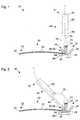
Die Vorrichtung
Am proximalen Ende
Die Handhabungseinrichtung
Am Gelenk
Zur Entriegelung der Arretierung
Das Lichtleitkabel
Eine wiederholte elastische Verformung des Lichtleitkabels
Ferner ist in
Ferner sind in
Die
In den
Die Gewindehülse
Am distalen Ende
Zur Montage eines Lichtleitkabels
Ein weiterer Vorteil des Schlitzes
Die
Die Arbeitskanaleinrichtung
Die Arbeitskanaleinrichtung
An einem Ende der Arbeitskanaleinrichtung
BezugszeichenlisteLIST OF REFERENCE NUMBERS
- 1010
- Vorrichtung zur manuellen RetraktionDevice for manual retraction
- 2020
- SpateleinrichtungSpateleinrichtung
- 2121
- proximales Ende der Spateleinrichtung
20 proximal end of thespatula device 20 - 2222
- distales Ende der Spateleinrichtung
20 distal end of thespatula device 20 - 2424
- Spülkanalirrigation channel
- 2626
- Kupplungseinrichtung am Spülkanal
24 Coupling device on the flushingchannel 24 - 3030
- Lichtleiteinrichtung in der Spateleinrichtung
20 Light-conducting device in thespatula device 20 - 3131
- Kupplung am proximalen Ende der Lichtleiteinrichtung
30 Coupling at the proximal end of thelight guide 30 - 3232
- Lichtaustrittsflächen am distalen Ende der Lichtleiteinrichtung
30 Light exit surfaces at the distal end of thelight guide 30 - 4040
- Handhabungseinrichtunghandling device
- 4141
- proximales Ende der Handhabungseinrichtung
50 proximal end of the handlingdevice 50 - 4242
- distales Ende der Handhabungseinrichtung
50 distal end of the handlingdevice 50 - 4444
- HolmHolm
- 4545
- Taillierung der Holme
44 Sidecut of thespars 44 - 5050
- Gewindehülsethreaded sleeve
- 5252
- Achse der Gewindehülse
50 Axle of the threadedsleeve 50 - 5656
- Außengewinde an der Gewindehülse
50 External thread on the threadedsleeve 50 - 5757
- Lumen der Gewindehülse
50 Lumen of the threadedsleeve 50 - 5858
- Schlitz in der Gewindehülse
50 Slot in the threadedsleeve 50 - 6060
- Handgriff an der Handhabungseinrichtung
50 Handle on thehandling device 50 - 6161
- proximales Ende des Handgriffs
60 proximal end of thehandle 60 - 6262
- distales Ende des Handgriffs
60 distal end of thehandle 60 - 6565
- Innengewinde im Handgriff
60 Internal thread in thehandle 60 - 6767
- Kanal im Handgriff
60 Canal in thehandle 60 - 7070
- Lichtleitkabeloptical cable
- 7272
- Kupplung am Lichtleitkabel
70 Clutch on thelight guide cable 70 - 8080
- Gelenk zwischen Spateleinrichtung
20 und Handhabungseinrichtung50 Joint betweenspatula device 20 andhandling equipment 50 - 8181
- Schwenkachse des Gelenks
80 Swivel axis of the joint80 - 8282
- Arretierung für das Gelenk
80 Locking for the joint80 - 8484
- Entriegelungsknopf für Arretierung
82 Release button for locking82 - 8686
- Richtung der Kraft zur Betätigung des Entriegelungsknopfes
84 Direction of force to operate therelease button 84 - 9090
- ArbeitskanaleinrichtungWorking channel device
- 9292
- Arbeitskanalworking channel
- 9494
- Schwalbenschwanzführung zwischen Arbeitskanaleinrichtung
90 und Spateleinrichtung20 Dovetail guide between workingchannel device 90 andspatula device 20 - 9595
- Verriegelung der Arbeitskanaleinrichtung
90 an der Spateleinrichtung20 Locking the workingchannel device 90 at thespatula device 20 - 9696
- ÜberwurfmutterNut
- 9797
- elastisches Klemmelementelastic clamping element
Claims (12)
Translated fromGermanPriority Applications (1)
| Application Number | Priority Date | Filing Date | Title |
|---|---|---|---|
| DE102010049759ADE102010049759A1 (en) | 2010-10-29 | 2010-10-29 | Device for manual retraction of muscle or for lifting another organ, has spatula device for rear driving of muscle or organ, handle and joint provided between proximal end of spatula device and handle |
Applications Claiming Priority (1)
| Application Number | Priority Date | Filing Date | Title |
|---|---|---|---|
| DE102010049759ADE102010049759A1 (en) | 2010-10-29 | 2010-10-29 | Device for manual retraction of muscle or for lifting another organ, has spatula device for rear driving of muscle or organ, handle and joint provided between proximal end of spatula device and handle |
Publications (1)
| Publication Number | Publication Date |
|---|---|
| DE102010049759A1true DE102010049759A1 (en) | 2012-05-03 |
Family
ID=45935533
Family Applications (1)
| Application Number | Title | Priority Date | Filing Date |
|---|---|---|---|
| DE102010049759APendingDE102010049759A1 (en) | 2010-10-29 | 2010-10-29 | Device for manual retraction of muscle or for lifting another organ, has spatula device for rear driving of muscle or organ, handle and joint provided between proximal end of spatula device and handle |
Country Status (1)
| Country | Link |
|---|---|
| DE (1) | DE102010049759A1 (en) |
Cited By (1)
| Publication number | Priority date | Publication date | Assignee | Title |
|---|---|---|---|---|
| EP4566510A1 (en) | 2023-12-08 | 2025-06-11 | Karl Storz SE & Co. KG | Surgical instrument and surgical system |
Citations (3)
| Publication number | Priority date | Publication date | Assignee | Title |
|---|---|---|---|---|
| US4052980A (en)* | 1976-06-10 | 1977-10-11 | Guenter A. Grams | Triaxial fiberoptic soft tissue retractor |
| US5891018A (en)* | 1997-09-19 | 1999-04-06 | Genzyme Corporation | Ball joint retractor |
| US6817978B2 (en)* | 2002-01-23 | 2004-11-16 | Teleflex-Ct Devices Incorporated | Illuminated retractor for use in connection with harvesting a blood vessel from the arm |
- 2010
- 2010-10-29DEDE102010049759Apatent/DE102010049759A1/enactivePending
Patent Citations (3)
| Publication number | Priority date | Publication date | Assignee | Title |
|---|---|---|---|---|
| US4052980A (en)* | 1976-06-10 | 1977-10-11 | Guenter A. Grams | Triaxial fiberoptic soft tissue retractor |
| US5891018A (en)* | 1997-09-19 | 1999-04-06 | Genzyme Corporation | Ball joint retractor |
| US6817978B2 (en)* | 2002-01-23 | 2004-11-16 | Teleflex-Ct Devices Incorporated | Illuminated retractor for use in connection with harvesting a blood vessel from the arm |
Cited By (1)
| Publication number | Priority date | Publication date | Assignee | Title |
|---|---|---|---|---|
| EP4566510A1 (en) | 2023-12-08 | 2025-06-11 | Karl Storz SE & Co. KG | Surgical instrument and surgical system |
Similar Documents
| Publication | Publication Date | Title |
|---|---|---|
| EP3876819B1 (en) | Endoscopic instrument | |
| DE69827276T2 (en) | CONTROLLED SURGICAL POSITIONING DEVICE IN DIFFERENT DIRECTIONS | |
| DE69732859T2 (en) | SURGICAL INSTRUMENT FOR ENDOSCOPE SURGERY | |
| DE3504292C1 (en) | Instrument for endoscopic interventions, especially for percutaneous gallstone removal or gallbladder surgery | |
| DE4321110C2 (en) | Surgical suction / irrigation instrument | |
| EP1714606B1 (en) | Endoscope | |
| EP3897343B1 (en) | Endoscope comprising quick-change tubes | |
| DE10024728A1 (en) | Unit cleaning endoscopic instrument window in-situ during intervention, comprises detachable end casing with insufflation- and flushing channels | |
| WO2005074787A1 (en) | Endoscope comprising a flexible probe | |
| DE102007008099A1 (en) | Hose arrangement for an endoscope | |
| EP1523932A1 (en) | Endoscope | |
| WO2011131660A1 (en) | Invasive instrument for treating vessels | |
| EP3266366B1 (en) | Adaptive laryngoscope and adaptive blade for a laryngoscope | |
| DE202009017988U1 (en) | Surgical instrument | |
| WO2004078046A1 (en) | Medical equipment for creating a surgical space for oral surgery | |
| DE19721138C1 (en) | Spreadable head for medical endoscope | |
| DE102004021676A1 (en) | Suction cups for surgery | |
| DE4014350C2 (en) | ||
| DE102010049759A1 (en) | Device for manual retraction of muscle or for lifting another organ, has spatula device for rear driving of muscle or organ, handle and joint provided between proximal end of spatula device and handle | |
| DE10341561A1 (en) | Surgical uterus manipulator has a grip that slides between a hold position and a release position | |
| DE102008034425A1 (en) | endoscope | |
| EP1699368A2 (en) | Medical cutting and/or holding instrument | |
| EP3909528A1 (en) | Tool insert | |
| WO2015097306A1 (en) | Rinsing and sucking device | |
| DE102010021463A1 (en) | Endoscope for use in ureterorenoscopy, comprises endoscope handgrip, which has grip plate, on which slider is guided, where slider stands in operating connection with elastic control element |
Legal Events
| Date | Code | Title | Description |
|---|---|---|---|
| R163 | Identified publications notified | ||
| R012 | Request for examination validly filed | Effective date:20130715 | |
| R016 | Response to examination communication | ||
| R081 | Change of applicant/patentee | Owner name:KARL STORZ SE & CO. KG INTELLECTUAL PROPERTY, DE Free format text:FORMER OWNER: KARL STORZ GMBH & CO. KG, 78532 TUTTLINGEN, DE Owner name:KARL STORZ SE & CO. KG, DE Free format text:FORMER OWNER: KARL STORZ GMBH & CO. KG, 78532 TUTTLINGEN, DE |