DE102010047843A1 - Bone bit set for use during osteotomy, has driver including closure that is brought into rotary position in inserted condition, and locked with opening in walls of hollow body in rotary position - Google Patents
Bone bit set for use during osteotomy, has driver including closure that is brought into rotary position in inserted condition, and locked with opening in walls of hollow body in rotary positionDownload PDFInfo
- Publication number
- DE102010047843A1 DE102010047843A1DE201010047843DE102010047843ADE102010047843A1DE 102010047843 A1DE102010047843 A1DE 102010047843A1DE 201010047843DE201010047843DE 201010047843DE 102010047843 ADE102010047843 ADE 102010047843ADE 102010047843 A1DE102010047843 A1DE 102010047843A1
- Authority
- DE
- Germany
- Prior art keywords
- closure
- hollow body
- bone
- set according
- opening
- Prior art date
- Legal status (The legal status is an assumption and is not a legal conclusion. Google has not performed a legal analysis and makes no representation as to the accuracy of the status listed.)
- Withdrawn
Links
Images


Classifications
- A—HUMAN NECESSITIES
- A61—MEDICAL OR VETERINARY SCIENCE; HYGIENE
- A61B—DIAGNOSIS; SURGERY; IDENTIFICATION
- A61B17/00—Surgical instruments, devices or methods
- A61B17/16—Instruments for performing osteoclasis; Drills or chisels for bones; Trepans
- A61B17/1604—Chisels; Rongeurs; Punches; Stamps
- A—HUMAN NECESSITIES
- A61—MEDICAL OR VETERINARY SCIENCE; HYGIENE
- A61B—DIAGNOSIS; SURGERY; IDENTIFICATION
- A61B17/00—Surgical instruments, devices or methods
- A61B17/16—Instruments for performing osteoclasis; Drills or chisels for bones; Trepans
- A61B17/1635—Instruments for performing osteoclasis; Drills or chisels for bones; Trepans for grafts, harvesting or transplants
- A—HUMAN NECESSITIES
- A61—MEDICAL OR VETERINARY SCIENCE; HYGIENE
- A61B—DIAGNOSIS; SURGERY; IDENTIFICATION
- A61B17/00—Surgical instruments, devices or methods
- A61B17/56—Surgical instruments or methods for treatment of bones or joints; Devices specially adapted therefor
- A61B17/58—Surgical instruments or methods for treatment of bones or joints; Devices specially adapted therefor for osteosynthesis, e.g. bone plates, screws or setting implements
- A61B17/88—Osteosynthesis instruments; Methods or means for implanting or extracting internal or external fixation devices
- A61B17/8897—Guide wires or guide pins
Landscapes
- Health & Medical Sciences (AREA)
- Surgery (AREA)
- Life Sciences & Earth Sciences (AREA)
- Biomedical Technology (AREA)
- Medical Informatics (AREA)
- Orthopedic Medicine & Surgery (AREA)
- Oral & Maxillofacial Surgery (AREA)
- Engineering & Computer Science (AREA)
- Dentistry (AREA)
- Heart & Thoracic Surgery (AREA)
- Nuclear Medicine, Radiotherapy & Molecular Imaging (AREA)
- Molecular Biology (AREA)
- Animal Behavior & Ethology (AREA)
- General Health & Medical Sciences (AREA)
- Public Health (AREA)
- Veterinary Medicine (AREA)
- Surgical Instruments (AREA)
Abstract
Description
Translated fromGermanDie Erfindung betrifft ein Knochenmeißelset, das Folgendes aufweist, nämlich einen Knochenmeißel zum Entnehmen einer Knochensäule aus einem Knochen, mit einem langerstreckten Hohlkörper, der einen mehreckigen Querschnitt aufweist, mit einer distalseitigen Schnittkante und mit einer proximalseitigen Öffnung zum Verbinden mit einem Eintreiber, und einen Eintreiber, der einen Verschluss aufweist, der in die Öffnung verriegelnd einbringbar ist.The invention relates to a bone chisel set comprising a bone chisel for removing a bone column from a bone, an elongate hollow body having a polygonal cross-section, a distal-side cutting edge, and a proximal-side opening for connection to a driver and a driver , which has a closure which can be introduced lockingly into the opening.
Ein Knochenmeißel in Form eines Osteotoms sowie ein chirurgisches Instrument zur Osteotomie ist aus der
Die Osteotomie ist eine Operationstechnik, bei der Knochen mit einem Meißel oder einer Säge durchtrennt werden. Die Knochenstücke werden an der Trennstelle wieder zusammengefügt. Dadurch können Überlängen oder Missbildungen beseitigt werden. Um ein Osteotom mit Meißelfuß und Meißelklinge so weiterzubilden, dass die damit gebildete Trennfuge ein Zusammenfügen der Knochenteile mit gegeneinander fixierter Lage bei vergrößerter Anlagefläche ermöglicht, weist der Meißel zur Bildung von Trennschnitten für die Osteomien zum Vorbereiten formschlüssiger Osteosynthesen unterschiedliche Meißelschneideformen auf. Darunter ist auch ein langerstreckter Hohlkörper, der einen mehreckigen Querschnitt aufweist und am distalen Ende eine umlaufende Schnittkante hat. Eine Wand des mehreckigen Hohlkörpers ist nach proximal verlängert und weist eine Öffnung auf, um den Meißel mit einem Eintreiber zu verbinden. Der Eintreiber weist einen Verschluss auf, der seitlich in die Öffnung verriegelnd einbringbar ist.Osteotomy is a surgical technique in which bones are severed with a chisel or saw. The pieces of bone are reassembled at the point of separation. As a result, excess lengths or malformations can be eliminated. In order to further develop an osteotome with a chisel foot and a chisel blade so that the parting line formed thereby enables the bone parts to be joined together with the contact surface being fixed relative to one another, the chisel has different chisel cutting forms for the preparation of separating cuts for the osteomias for preparing positive-locking osteosyntheses. Among them is also an elongated hollow body, which has a polygonal cross-section and at the distal end has a circumferential cutting edge. One wall of the polygonal hollow body is extended proximally and has an opening to connect the bit to a driver. The driver has a closure which can be inserted laterally into the opening in a locking manner.
Gegenstand der vorliegenden Erfindung ist ein Knochenmeißelset, das bei der Rekonstruktion des Kreuzbandes des menschlichen Knies, insbesondere bei der Rekonstruktion des vorderen Kreuzbandes eingesetzt werden kann.The present invention is a bone chisel set that can be used in the reconstruction of the cruciate ligament of the human knee, in particular in the reconstruction of the anterior cruciate ligament.
Bei dieser Operationstechnik wird beispielsweise im Unterschenkelknochen im Bereich des Knies eine Sacklochöffnung bewerkstelligt, in die ein Sehnentransplantat eingelegt und fixiert wird. Der so fixierte Sehnenersatz wird dann zum Oberschenkelknochen geführt und dort entsprechend fixiert.In this surgical technique, for example, a blind hole opening is made in the lower leg bone in the region of the knee, into which a tendon transplant is inserted and fixed. The thus fixed tendon replacement is then guided to the femur and fixed there accordingly.
Werden Sacklochöffnungen mit einer von der kreisförmigen Geometrie abweichenden Geometrie erwünscht, ist ein Bohren mit einem drehenden Werkzeug zur Bewerkstelligung der Sacklochöffnung nicht möglich.If blind-hole openings with a geometry deviating from the circular geometry are desired, drilling with a rotating tool to effect the blind-hole opening is not possible.
Dazu kann ein Hohlmeißel eingesetzt werden, der mit dem Eintreiber durch die äußere harte Knochenhaut bis in die innere schwammartige Knochensubstanz eingetrieben wird. Dabei tritt eine Säule an Knochenmaterial in den Innenraum des Hohlkörpers des Knochenmeißels ein. Diese Knochensäule wird dann vom verbleibenden Material abgebrochen, beispielsweise durch Hin- und Herbewegen des Hohlmeißels und das abgelöste Knochensäulenstück wird samt dem Hohlmeißel abgenommen.For this purpose, a chisel can be used, which is driven with the driver through the outer hard periosteum into the inner sponge-like bone substance. In this case, a column of bone material enters the interior of the hollow body of the bone chisel. This bone column is then broken off from the remaining material, for example by reciprocating the gouges and the detached bone column piece is removed together with the chisel.
Die Sehne wird entsprechend der angewandten Operationstechnik mit einer Interferenzschraube in der Sacklochöffnung im Knochen fixiert. Je nachdem, ob es sich bei der Sehne um eine doppelsträngige oder eine viersträngige Sehne handelt, werden in den verbleibenden Zwischenräumen Dübel aus Knochenmaterial, das von der entnommenen Knochensäule stammt, eingetrieben.The tendon is fixed according to the surgical technique used with an interference screw in the blind hole opening in the bone. Depending on whether the tendon is a double-stranded or a quadrilateral tendon, dowels of bone material originating from the removed bone column are driven in the remaining interstices.
Bei der Bone-Tendon-Bone(BTB)-Technik mit doppelsträngigem Sehnentransplantat wird in ein rechteckiges Loch ein Knochenblock mit einem Sehnentransplantat eingezogen.The Bone-Tendon-Bone (BTB) technique with double-stranded tendon graft introduces a block of bone with a tendon graft into a rectangular hole.
Ein entscheidender Faktor für eine erfolgreiche Rekonstruktion des vorderen Kreuzbandes ist die Ausrichtung der Sacklochöffnung derart, dass das daraus in Richtung des Kniegelenks vorspringende Sehnentransplantat eine Ausrichtung hat, die der Ausrichtung des natürlichen Kreuzbandes entspricht.A decisive factor for a successful reconstruction of the anterior cruciate ligament is the alignment of the blind hole opening such that the tendon graft projecting therefrom in the direction of the knee joint has an orientation that corresponds to the orientation of the natural cruciate ligament.
Daher ist die Ausrichtung der Mittellängsachse des zu erzeugenden Sackloches von entscheidender Bedeutung.Therefore, the alignment of the central longitudinal axis of the blind hole to be produced is of crucial importance.
Das erfordert aber entsprechende Maßnahmen, um einen solchen Hohlmeißel auch zielgerecht in den Knochen einzuführen.But this requires appropriate measures to introduce such a chisel also targeted in the bone.
Dies ist bei der Osteotomie kein Erfordernis, denn dort soll der Knochen vollständig durchtrennt werden und dann an den gleichmäßig ausgeformten Trennstellen wieder möglichst gut haftend zusammengefügt werden.This is not a requirement in osteotomy, because there the bone is to be completely severed and then reassembled as well as possible at the uniformly shaped separation points.
Aufgabe der vorliegenden Erfindung ist es, dass die Verbindung zwischen Knochenmeißel und Eintreiber einfach bewerkstelligbar und auch einfach wieder lösbar ist und ein gezieltes Handhaben des Zusammenbaus sowie eine effektive Übertragung der Kräfte vom Eintreiber auf den Hohlmeißel erlaubt.Object of the present invention is that the connection between the bone chisel and Eintreiber easily accomplished and also easily solvable and allows targeted handling of the assembly and effective transfer of forces from the driver to the chisel.
Erfindungsgemäß wird die Aufgabe dadurch gelöst, dass der Verschluss derart ausgebildet ist, dass dieser in einer ersten Drehstellung über den proximalseitig offenen Querschnitt in den Hohlkörper einführbar ist, und, im eingeführten Zustand, in eine zweite Drehstellung verbringbar ist, in der der Verschluss mit einer Öffnung in der Wand des Hohlkörpers verriegelt.According to the invention the object is achieved in that the closure is designed such that it is insertable in a first rotational position on the proximal side open cross section in the hollow body, and, in the inserted state, can be brought into a second rotational position, in which the closure with a Opening locked in the wall of the hollow body.
Der Verschluss wird in einer ersten Drehstellung von proximal her in den Innenraum des Hohlkörpers des Hohlmeißels eingeführt. The closure is introduced in a first rotational position from proximally into the interior of the hollow body of the gullet.
Diese Maßnahme hat den Vorteil, dass dieser Raum ohnehin vorhanden ist, so dass nicht, wie beim eingangs genannten Stand der Technik, hochstehende, möglicherweise instabile Wände vorgesehen werden müssen, in die seitlich der Verschluss eingesetzt wird. Nach Einführen des Verschlusses in das Innere des Knochenmeißels wird der Verschluss in eine zweite Drehstellung verdreht, in der er mit einer Öffnung in der Wand des Hohlkörpers verriegelt.This measure has the advantage that this space is present anyway, so that not, as in the aforementioned prior art, high, possibly unstable walls must be provided in the side of the closure is used. After insertion of the closure into the interior of the bone chisel, the closure is rotated into a second rotational position, in which it locks with an opening in the wall of the hollow body.
Dies führt zu einer sehr einfachen und ergonomischen Handhabung. Der Hohlmeißel und der Eintreiber werden in einer linear gerichteten Bewegung zusammengefügt, wobei der Verschluss von proximal in den Hohlkörper eingeführt wird. Danach werden die beiden Körper relativ zueinander verdreht. Dabei kann der Hohlmeißel gegenüber dem Eintreiber, der Eintreiber gegenüber dem Hohlmeißel oder beide können gleichzeitig gedreht werden, wobei der Verschluss in seine verriegelnde zweite Drehstellung gebracht wird. Der Verschluss bewegt sich dabei in die Öffnung in der Wand des Hohlkörpers hinein und verriegelt den Eintreiber gegenüber einem axialen Abziehen vom Hohlmeißel. Die Kräfte beim Eintreiben können vom Verschluss auf den Hohlkörper verteilt werden.This leads to a very simple and ergonomic handling. The chisel and the driver are assembled in a linear directional motion, with the closure inserted proximally into the hollow body. Thereafter, the two bodies are rotated relative to each other. In this case, the chisel relative to the driver, the Eintreiber opposite the chisel or both can be rotated simultaneously, wherein the closure is brought into its locking second rotational position. The closure thereby moves into the opening in the wall of the hollow body and locks the Eintreiber against axial withdrawal from the chisel. The forces during driving can be distributed from the closure to the hollow body.
Dies sind einfach zu bewerkstelligende bauliche Maßnahmen, die auch, was in der Medizintechnik äußerst wichtig ist, einfach zu reinigen und zu sterilisieren sind, da keine unzugänglichen Bakteriennischen vorhanden sind.These are easy to implement structural measures, which are also, which is extremely important in medical technology, easy to clean and sterilize, since there are no inaccessible bacterial niches.
Die Außenseite des Verschlusses des Eintreibers kann problemlos gereinigt und sterilisiert werden.The outside of the fastener of the driver can be easily cleaned and sterilized.
Auch eine Öffnung im Innenraum des Hohlkörpers des Hohlmeißels kann einfach gereinigt werden, so dass auch hier dieses Erfordernis durch einfache konstruktive Maßnahmen erfüllt ist. Das Set aus zusammengebautem Hohlmeißel und Eintreiber ist als schlankes, dennoch kompaktes Gerät auszubilden, so dass eine einfache Handhabung, insbesondere das Anzielen und das Ansetzen am Knochen, möglich ist.Also, an opening in the interior of the hollow body of the gullet can be easily cleaned, so that this requirement is met by simple design measures here. The set of assembled chisel and driver is designed as a slim, yet compact device, so that an easy handling, especially the targeting and the attachment to the bone, is possible.
In einer weiteren Ausgestaltung der Erfindung ist der Querschnitt des Hohlkörpers viereckig, und in zwei gegenüberliegenden Wänden ist eine Öffnung vorhanden, in die jeweils der Verschluss einführbar ist.In a further embodiment of the invention, the cross section of the hollow body is quadrangular, and in two opposite walls, an opening is present, in each of which the closure is insertable.
Hier sind somit zwei Kontaktstellen zwischen Verschluss und Hohlkörper vorhanden, so dass die Kräfte beim Einschlagen besonders gut und auch gleichmäßig auf den Hohlkörper des Hohlmeißels übertragbar sind.Here, therefore, two contact points between the closure and the hollow body are present, so that the forces are particularly good when transferring and even transferable to the hollow body of the hollow chisel.
In einer weiteren Ausgestaltung der Erfindung ist der Querschnitt des Hohlmeißels rechteckig.In a further embodiment of the invention, the cross section of the chisel is rectangular.
Diese Maßnahme hat den Vorteil, dass eine rechteckige Sacklochöffnung bewerkstelligt werden kann, in der ein Sehnenersatz in der sogenannten Doppelstrangtechnik einsetzbar ist. Bei dieser Doppelstrangtechnik wird die Sehne einmal umgeschlagen, so dass zwei nebeneinander liegende Sehnenstränge vorhanden sind, die im Querschnitt etwa die Kontur einer ”8” aufweisen. Diese beiden Stränge können dann, wie bei dem doppelsträngigen vorderen Kreuzband, anatomisch exakt an den gegenüberliegenden Knochen geführt und dort fixiert werden. Ein solcher Doppelstrang kann einfach in eine rechteckförmige Öffnung eingeführt und fixiert werden. Je nach Technik werden dazu Interferenzschrauben und/oder Knochendübel aus dem zuvor entnommenen Knochenmaterial zur Fixierung eingesetzt.This measure has the advantage that a rectangular blind hole opening can be accomplished, in which a tendon replacement in the so-called double-stranded technique can be used. In this double-stranded technique, the tendon is turned over once, so that two adjacent tendon cords are present, which have approximately the contour of an "8" in cross section. These two strands can then, as in the case of the double-stranded anterior cruciate ligament, be anatomically guided exactly to the opposite bone and fixed there. Such a double strand can be easily inserted and fixed in a rectangular opening. Depending on the technique, interference screws and / or bone dowels from the previously removed bone material are used for fixation.
In einer weiteren Ausgestaltung der Erfindung ist die Öffnung als eine durch die Wand hindurchgehende Öffnung ausgebildet.In a further embodiment of the invention, the opening is formed as an opening passing through the wall.
Diese Maßnahme hat den Vorteil, dass eine durchgehende Öffnung die Möglichkeit eröffnet, dass der Verschluss, bei der Drehbewegung während der Verbringung von der ersten Drehstellung in die zweite Drehstellung, seitlich aus der Öffnung herausfahren kann, oder, wenn das gewünscht ist, der Verschluss in der zweiten Drehstellung seitlich aus der Öffnung herausragt.This measure has the advantage that a through opening opens up the possibility that the closure can move out of the opening laterally during the movement from the first rotational position to the second rotational position, or, if so desired, the closure in the second rotational position laterally protrudes from the opening.
Eine solche Öffnung ist auch sehr einfach zu reinigen und bietet kaum Bakteriennischen.Such an opening is also very easy to clean and offers little bacteria niches.
In einer weiteren Ausgestaltung der Erfindung weist der Verschluss eine distalseitige Anlage auf, über die er an einer Anlagefläche der Öffnung in der zweiten Drehstellung zum Liegen kommt.In a further embodiment of the invention, the closure has a distal-side contact, via which it comes to rest on a contact surface of the opening in the second rotational position.
Diese Maßnahme hat den Vorteil, dass klar definierte Kraftübertragungsflächen vorhanden sind, über die die Kraft vom Eintreiber auf den Hohlmeißel übertragbar ist.This measure has the advantage that clearly defined force transmission surfaces are present, via which the force can be transmitted from the driver to the chisel.
In einer weiteren Ausgestaltung der Erfindung ist die Anlagefläche als eine sich in der Querschnittsebene des Hohlmeißels erstreckende Kante einer fensterartigen Öffnung in der Wand ausgebildet.In a further embodiment of the invention, the abutment surface is formed as an edge of a window-like opening in the wall extending in the cross-sectional plane of the chisel.
Über eine solche Kante kann besonders gut die Kraft von dem Verschluss in axialer Richtung auf den Hohlkörper des Meißels übertragen werden.About such an edge can be transferred to the hollow body of the bit particularly well the force of the closure in the axial direction.
In einer weiteren Ausgestaltung der Erfindung ist der Querschnitt des Hohlkörpers rechteckförmig, wobei in den breiteren Wänden die Öffnungen aufgespart sind, in die Abschnitte des Verschlusses in der zweiten Drehstellung eintreten können. In a further embodiment of the invention, the cross section of the hollow body is rectangular, wherein in the wider walls, the openings are stored, can enter into the sections of the closure in the second rotational position.
Das Vorsehen dieser Öffnungen in den breiteren Wänden eröffnet die Möglichkeit, den Verschluss in der Querschnittsebene des Hohlkörpers in einer Richtung relativ lang auszubilden, wobei dann Teile des Verschlusses in der zweiten Drehstellung in die Öffnungen hineinreichen oder sogar über diese seitlich hinausreichen.The provision of these openings in the wider walls opens up the possibility of making the closure in the cross-sectional plane of the hollow body relatively long in one direction, in which case parts of the closure in the second rotational position extend into the openings or even extend laterally beyond them.
In einer weiteren Ausgestaltung der Erfindung weist der Verschluss einen Verschlusskörper auf, dessen Querschnittsmaß in einer ersten Richtung dem lichten Innenmaß des kürzeren Querschnittsmaßes des Hohlkörpers entspricht, und die Größe und Lage der beiden Öffnungen in den breiteren Wänden des Hohlkörpers so gewählt ist, dass gegenüberliegende äußere Abschnitte des Verschlusskörpers in diese Öffnungen beim Drehen in die zweite Drehstellung eintreten.In a further embodiment of the invention, the closure has a closure body whose cross-sectional dimension in a first direction corresponds to the inside dimension of the shorter cross-sectional dimension of the hollow body, and the size and position of the two openings in the wider walls of the hollow body is selected so that opposite outer Enter sections of the closure body in these openings when turning into the second rotational position.
Diese Maßnahme hat den Vorteil, dass die Größe des Verschlusskörpers in der schmaleren Querschnittsrichtung des rechteckförmigen Querschnittes gleich dem lichten Innenmaß des Hohlkörpers entspricht, so dass dieser gerade passend von distal her in den Hohlkörper eingeschoben werden kann. Das Maß in die längere Querschnittsebenenrichtung ist so gewählt, dass in der zweiten Drehstellung äußere Abschnitte des Verschlusskörpers in diese Öffnungen eintreten kann.This measure has the advantage that the size of the closure body in the narrower cross-sectional direction of the rectangular cross-section equal to the clear internal dimension of the hollow body, so that it can be inserted just fitting from distal into the hollow body. The dimension in the longer cross-sectional plane direction is chosen so that in the second rotational position, outer sections of the closure body can enter these openings.
In einer weiteren Ausgestaltung der Erfindung weist der Verschlusskörper ein Querschnittsmaß in der zweiten Richtung, die senkrecht zur ersten Richtung verläuft, auf, das dem Außenmaß des Hohlkörpers in Richtung des kürzeren Querschnittsmaßes des Hohlkörpers entspricht.In a further embodiment of the invention, the closure body has a cross-sectional dimension in the second direction, which is perpendicular to the first direction, which corresponds to the outer dimension of the hollow body in the direction of the shorter cross-sectional dimension of the hollow body.
Diese Maßnahme hat den Vorteil, dass einerseits der Verschlusskörper beim Einführen in den Hohlkörper in einer Querschnittsrichtung, nämlich in Richtung der kürzeren Seite des Rechteckes, gerade passend einschiebbar ist und, nach Verdrehen um 90° genau fluchtend mit der Außenseite des Hohlkörpers zum Liegen kommt.This measure has the advantage that on the one hand, the closure body during insertion into the hollow body in a cross-sectional direction, namely in the direction of the shorter side of the rectangle, just fitting inserted and, after rotation by 90 ° exactly aligned with the outside of the hollow body comes to rest.
Der Verschlusskörper ist ebenfalls ein Rechteck, dessen eines Maß eben genau dem lichten Innenquerschnittsmaß des Hohlkörpers in der kürzeren Rechteckrichtung entspricht, in der senkrecht dazu verlaufenden längeren Rechteckrichtung aber genau exakt das Außenmaß des Hohlkörpers in der kürzeren Rechteckrichtung aufweist.The closure body is also a rectangle, one measure of which exactly corresponds to the clear inner cross-sectional dimension of the hollow body in the shorter rectangular direction, but in the perpendicular thereto extending longer rectangular direction but exactly the outer dimension of the hollow body in the shorter rectangular direction.
Dieser Verschlusskörper tritt beim Verdrehen mit seinen Ecken über die Öffnungen und auch über die Außenkontur hinaus, liegt aber in der zweiten Drehstellung exakt fluchtend mit der Außenseite des Hohlkörpers.This closure body occurs during rotation with its corners beyond the openings and also beyond the outer contour, but lies in the second rotational position exactly aligned with the outside of the hollow body.
Dadurch stehen keinerlei Teile des Verschlusses bzw. des Verschlusskörpers seitlich über die Kontur des Hohlmeißels hinaus, so dass der Hohlmeißel relativ kurz ausgebildet werden kann. Er kann in diesem Bereich auch in den Knochen hineingetrieben werden.As a result, no parts of the closure or the closure body are laterally beyond the contour of the hollow chisel, so that the chisel can be made relatively short. It can also be driven into the bone in this area.
In einer weiteren Ausgestaltung der Erfindung ist in einen Hohlraum, der zwischen der Außenkante des Verschlusskörpers in seiner zweiten Drehstellung und der gegenüberliegenden Innenwand des Hohlkörpers vorhanden ist, ein Riegel einschiebbar, der eine Bewegung des Verschlusskörpers aus der zweiten Drehstellung in die erste Drehstellung sperrt.In a further embodiment of the invention, in a cavity which is present between the outer edge of the closure body in its second rotational position and the opposite inner wall of the hollow body, a bolt can be inserted, which blocks a movement of the closure body from the second rotational position to the first rotational position.
Bei der zuvor beschriebenen Geometrie verbleibt, bei in die zweite Drehstellung verdrehtem Verschlusskörper, im Innern des Hohlkörpers zwischen der Innenwand der kürzeren Rechteckseiten des rechteckförmigen Querschnitts des Hohlkörpers und dem Verschlusskörper ein Hohlraum, der dazu benötigt wird, um den rechteckförmigen Verschlusskörper im Innern des Hohlkörpers verdrehen zu können. Der nachträglich einschiebbare Riegel sperrt nunmehr eine ungewünschte Verdrehung des Verschlusskörpers aus seiner zweiten Drehstellung in die erste Drehstellung.In the geometry described above remains, with twisted in the second rotational position closure body, inside the hollow body between the inner wall of the shorter rectangular sides of the rectangular cross section of the hollow body and the closure body, a cavity which is required to rotate the rectangular closure body in the interior of the hollow body to be able to. The subsequently insertable bolt now locks an undesired rotation of the closure body from its second rotational position to the first rotational position.
In einer weiteren Ausgestaltung der Erfindung ist der Verschluss als ein distales Ende des Eintreibers ausgebildet, der einen stabförmigen Körper aufweist und einen proximalseitigen Handgriff hat.In a further embodiment of the invention, the closure is designed as a distal end of the driver, which has a rod-shaped body and has a proximal-side handle.
Diese Maßnahme hat den Vorteil, dass eine besonders ergonomische Handhabung möglich ist. Dabei wird der Eintreiber von einer Hand an dem proximalseitigen Handgriff ergriffen und der mit einer anderen Hand erfasste Knochenmeißel kann dann auf den Verschluss am distalen Ende des Eintreibers einfach aufgeschoben und verdreht werden.This measure has the advantage that a particularly ergonomic handling is possible. In this case, the driver is gripped by one hand on the proximal-side handle and the bone chisel grasped with another hand can then simply be pushed onto the closure on the distal end of the driver and twisted.
In einer weiteren Ausgestaltung der Erfindung ist der Riegel als längs des stabförmigen Körpers des Eintreibers verschiebbares Teil ausgebildet, von dem zumindest eine Rastnase nach distal vorspringt, die in den Hohlraum zwischen Verschlusskörper und Innenwand des Hohlkörpers einschiebbar ist.In a further embodiment of the invention, the bolt is designed as a part displaceable along the rod-shaped body of the driver, from which at least one detent protrudes distally, which can be pushed into the cavity between the closure body and the inner wall of the hollow body.
Diese Maßnahme hat den Vorteil, dass die Handhabung dadurch sehr vereinfacht wird, dass beim Kuppeln von Verschluss und Knochenmeißel der Riegel zunächst längs des stabförmigen Körpers nach proximal verschoben ist.This measure has the advantage that the handling is greatly simplified by the fact that, when the closure and bone chisel are coupled, the latch is initially displaced proximally along the rod-shaped body.
Nachdem der Hohlmeißel aufgeschoben und der Verschluss in seine zweite Drehstellung verbracht ist, wird der Riegel längs des stabförmigen Körpers nach distal verschoben, bis die zumindest eine Rastnase in den Hohlraum zwischen Verschlusskörper und Innenwand des Hohlkörpers eingeschoben ist. Da bei der Rechtecksymmetrie beidseits des Verschlusskörpers ein solcher Hohlraum vorhanden ist, können entsprechend zwei Rastnasen vorgesehen sein. After the chisel is pushed and the closure is moved to its second rotational position, the bolt is displaced distally along the rod-shaped body until the at least one latching nose is inserted into the cavity between the closure body and the inner wall of the hollow body. Since in the case of the rectangular symmetry such a cavity is present on both sides of the closure body, correspondingly two latching lugs can be provided.
In einer weiteren Ausgestaltung der Erfindung weist die Rastnase einen seitlichen Vorsprung auf, der in eine Aussparung in der Innenwand einfahrbar ist.In a further embodiment of the invention, the locking lug on a lateral projection which is retractable into a recess in the inner wall.
Diese Maßnahme hat den Vorteil, dass diese eingefahrene Rastnase ein ungewolltes axiales Verschieben des Riegels sperrt.This measure has the advantage that this retracted detent locks an unintentional axial displacement of the bolt.
In einer weiteren Ausgestaltung der Erfindung ist der seitliche Vorsprung als abgerundeter Höcker ausgebildet, der in die Aussparung einfahrbar ist, und bei Anwenden einer Zugkraft in axialer Richtung wieder aus der Aussparung ausfahrbar ist.In a further embodiment of the invention, the lateral projection is formed as a rounded bump, which is retractable into the recess, and when applying a tensile force in the axial direction is again extendable from the recess.
Diese Maßnahme hat erhebliche handhabungsmäßige Vorteile.This measure has considerable handling advantages.
Zum Bewerkstelligen der Verriegelung wird der Riegel soweit eingeschoben, bis die seitlich vorspringende Rastnase in die Aussparung an der Innenwand im Hohlkörper eingefahren ist. Dies ist durch ein Klickgeräusch zu erkennen. Der Hohlkörper des Hohlmeißels ist nunmehr vor einem Abfallen oder Abgleiten vom Eintreiber gehindert, so dass diese beiden zusammengefügten Bauteile Hohlmeißel und Eintreiber durch Ergreifen des Eintreibers am Griff zusammen handhabbar sind. Zum Lösen der Verriegelung wird der Riegel nach proximal bewegt. Die abgerundeten Höcker verursachen ein seitliches nach innen Ausweichen der vorstehenden elastischen Rastnasen. Danach kann der Verschluss wieder in seine erste Drehstellung gebracht und der Eintreiber kann nach distal vom Innenraum des Hohlkörpers des Meißels abgezogen werden.To accomplish the locking of the bolt is inserted so far until the laterally projecting locking lug is retracted into the recess on the inner wall in the hollow body. This can be recognized by a clicking sound. The hollow body of the gullet is now prevented from falling or slipping by the driver, so that these two assembled components of the chisel and driver can be handled together by gripping the driver on the handle. To unlock the latch, the latch is moved proximally. The rounded bumps cause a lateral inward evasion of the protruding elastic locking lugs. Thereafter, the closure can be brought back into its first rotational position and the driver can be withdrawn distally from the interior of the hollow body of the chisel.
In einer weiteren Ausgestaltung der Erfindung ist die seitliche Aussparung in der Innenwand als eine durchgehende Öffnung ausgebildet.In a further embodiment of the invention, the lateral recess in the inner wall is formed as a continuous opening.
Diese Maßnahme hat den Vorteil, dass von der Außenseite her die in die Öffnung eingerasteten Höcker radial nach innen gedrückt werden können und dadurch dann der Riegel zum Abziehen freigegeben ist. In diesem Fall können dann die Höcker auch als eckige Höcker ausgebildet sein, die ein Abziehen ohne vorheriges Eindrücken komplett sperren. Der Riegel kann, um diese Bewegung zu erleichtern, aus einem Kunststoffmaterial hergestellt sein.This measure has the advantage that from the outside, the catches latched in the opening can be pressed radially inwards, thereby releasing the catch for removal. In this case, then the cusps can be designed as an angular cusps that completely lock a peeling without previous impressions. The latch may be made of a plastic material to facilitate this movement.
In einer weiteren Ausgestaltung der Erfindung ist ein durch den Eintreiber mittig durchgehender Kanal vorhanden, durch den ein Führungsdraht einführbar ist, der auch durch den Hohlkörper des Knochenmeißels durchreicht.In a further embodiment of the invention, a passage through which the driver passes centrally is provided, through which a guide wire can be inserted, which also extends through the hollow body of the bone chisel.
Diese Maßnahme hat den Vorteil, dass mit dem Führungsdraht ein besonders exaktes und zielgerichtetes Eintreiben des Knochenmeißels möglich ist.This measure has the advantage that with the guide wire, a particularly precise and targeted driving the bone bit is possible.
Der Zieldraht kann vorher in den Knochen eingetrieben und dessen Orientierung kann exakt vermessen werden. Ist der Zieldraht entsprechend zutreffend ausgerichtet, kann dann der Zusammenbau aus Hohlmeißel und Eintreiber auf den bereits eingetriebenen Zieldraht aufgeschoben werden. Die distalseitige Schnittkante wird durch Verdrehen des Zusammenbaus aus Hohlmeißel und Eintreiber um den Zieldraht in die gewünschte Position ausgerichtet.The target wire can be previously driven into the bone and its orientation can be measured accurately. If the target wire is aligned correctly, then the assembly of gouges and driver can be pushed onto the already driven target wire. The distal cutting edge is aligned to the desired position by twisting the bit and driver assembly around the target wire.
In einer weiteren Ausgestaltung der Erfindung ist im Hohlkörper des Knochenmeißels eine Führung für den Führungsdraht angeordnet.In a further embodiment of the invention, a guide for the guide wire is arranged in the hollow body of the bone chisel.
Diese Maßnahme hat den Vorteil, dass bei Aufschieben des Hohlmeißels auf den Führungsdraht dieser exakt geführt ist.This measure has the advantage that when pushing the gouge on the guidewire this is exactly guided.
In einer weiteren Ausgestaltung der Erfindung weist der Eintreiber eine Schlagplatte auf, die dann, wenn sich der Verschluss in seiner zweiten Drehstellung befindet, auf einer proximalen Endkante des Hohlkörpers zum Liegen kommt.In a further embodiment of the invention, the driver has a striking plate which, when the closure is in its second rotational position, comes to rest on a proximal end edge of the hollow body.
Das Vorsehen einer solchen Schlagplatte hat den Vorteil, dass die beim Eintreiben des Zusammenbaus notwendige Kraft von dieser Schlagplatte gleichmäßig auf die proximale Endkante des Hohlkörpers verteilt übertragen werden kann. In diesem Fall kann dann der Verschluss entsprechend feingliedrig ausgebildet sein, da er lediglich ein Abfallen des Knochenmeißels vom Eintreiber verhindern soll, in diesem Fall aber dann nicht zwingender Weise zur Kraftübertragung herangezogen werden muss.The provision of such a striking plate has the advantage that the necessary during the driving of the assembly force of this striking plate can be transmitted evenly distributed to the proximal end edge of the hollow body. In this case, the closure can then be designed in accordance with fine-limbed, since it is only intended to prevent a drop of the bone chisel from the driver, but in this case then does not necessarily have to be used for power transmission.
Diese Bauweise wird bei besonders kleinen und dünnwandigen Hohlmeißeln zu bevorzugen sein.This construction will be preferable for particularly small and thin-walled hollow chisels.
Es versteht sich, dass die vorstehend genannten und die nachstehend noch zu erläuternden Merkmale nicht nur in den jeweils angegebenen Kombinationen, sondern auch in anderen Kombinationen oder in Alleinstellung einsetzbar sind, ohne den Rahmen der vorliegenden Erfindung zu verlassen.It is understood that the features mentioned above and those yet to be explained below can be used not only in the particular combinations indicated, but also in other combinations or in isolation, without departing from the scope of the present invention.
Die Erfindung wird nachfolgend anhand der beiliegenden Zeichnungen näher beschrieben und erläutert. Es zeigen:The invention will be described and explained in more detail with reference to the accompanying drawings. Show it:
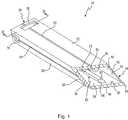
Ein in den
Das Knochenmeißelset
Der in
Der Hohlkörper
Am distalen Ende
Jede Welle
Aus der Seitenansicht von
Aus der Seitenansicht von
Aus der Draufsicht von
Wie ebenfalls aus
Wie aus den
Eine Schnittkante
Aus der Draufsicht von
Wie insbesondere aus
Die Führung
Dem Innenraum zugewandt weist die Leiste
Entsprechend springt von der gegenüberliegenden unteren Wand
Wird in den Hohlkörper
Die Wand
In der Wand
Wie insbesondere aus
Der Sinn und die Funktionsweise dieser Öffnungen
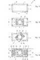
Aus den Darstellungen von
Der Verschluss
Der Verschlusskörper
Der rechteckige Verschlusskörper
Ferner weist der rechteckige Verschlusskörper
Diese Ausgestaltung des Verschlusses
Die in
Aus
In
Aus
Die schmalen gegenüberliegenden Rechteckkanten des Verschlusskörpers
In dieser Drehstellung existiert, wie das insbesondere aus
In diese Hohlräume
Die Rastnase
Die beiden nach distal vorstehenden Rastnasen
Die Orientierung, die Bemaßung der Rastnasen
Dazu wird der Riegel
Die seitlich vorstehenden Höcker
Der Riegel
Beim Abziehen des Riegels
Es ist auch möglich, von der Außenseite mit zwei Fingern die Höcker
Danach kann der Riegel
Wie insbesondere in
Zur Bewerkstelligung einer Sacklochöffnung, beispielsweise im Oberschenkelknochen, wird zunächst der Zieldraht
Die Ausrichtung und die Lage kann vom Operateur genau festgelegt und überprüft werden. Anschließend wird der Zusammenbau aus Knochenmeißel
Die Schnittkante
Nach Abtrennen der Knochensäule wird das komplette Knochenmeißelset
Nach Lösen von Knochenmeißel und Eintreiber
Soll in die resultierende Sacklochöffnung mit rechteckförmigem Querschnitt ein Sehnentransplantat mit zwei nebeneinander liegenden Bündeln eingeschoben werden, verbleibt in den Engstellen bzw. Einschnürungen der Kontur in Form einer ”8” ausreichend Platz, um entweder Interferenzschrauben oder entsprechende Knochendübel einzuschieben. Die Sehne kann auch in ein rechteckiges Knochenmaterialstück eingefädelt sein und dieser Zusammenbau wird in die Sacklochbohrung eingesetzt.If a tendon graft with two adjacent bundles is to be inserted into the resulting blind-hole opening with a rectangular cross-section, sufficient space remains in the constrictions or constrictions of the contour in the form of an "8" to either insert interference screws or corresponding bone dowels. The tendon may also be threaded into a rectangular piece of bone material and this assembly is inserted into the blind bore.
Mit dem zuvor beschriebenen Knochenmeißelset ist eine einfache Handhabung beim Koppeln von Knochenmeißel und Eintreiber und auch beim Entkoppeln möglich. Zugleich kann dann das Knochenmeißelset
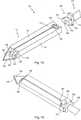
In den
Auch dieses Knochenmeißelset
Im Hohlkörper
Der Steg
Mittig weist er einen Kanal
Der Steg
Der Hohlkörper
Die gesamte distale Stirnkante des Hohlkörpers
Der Eintreiber
Der Verschluss
In der ”oberen” Wand
Auch hier endet der Hohlkörper
Allerdings ist die Längserstreckung des Verschlusskörpers
Aus
Der Abstand zwischen der distalen Seite der Schlagplatte
Auch hier wird im Prinzip dieselbe Operationstechnik beim Eintreiben bzw. Ausstanzen der Knochensäule verwendet, wie zuvor beschrieben.Again, in principle, the same surgical technique used in driving or punching the bone column, as described above.
Nach dem Einsatz wird dann der Verschlusskörper
Es ist ersichtlich, dass es sich bei beiden Ausführungsbeispielen um einfache Bauteile handelt, die an der Kupplung zwischen Knochenmeißel und Eintreiber beteiligt sind.It can be seen that both embodiments are simple components involved in the coupling between bone bit and driver.
All diese Bauelemente sind einfach zu reinigen, zu desinfizieren und zu sterilisieren, so dass diese Knochenmeißelsets für einen mehrfachen Einsatz geeignet sind.All of these components are easy to clean, sanitize and sterilize, making these bone chisel sets suitable for multiple use.
ZITATE ENTHALTEN IN DER BESCHREIBUNG QUOTES INCLUDE IN THE DESCRIPTION
Diese Liste der vom Anmelder aufgeführten Dokumente wurde automatisiert erzeugt und ist ausschließlich zur besseren Information des Lesers aufgenommen. Die Liste ist nicht Bestandteil der deutschen Patent- bzw. Gebrauchsmusteranmeldung. Das DPMA übernimmt keinerlei Haftung für etwaige Fehler oder Auslassungen.This list of the documents listed by the applicant has been generated automatically and is included solely for the better information of the reader. The list is not part of the German patent or utility model application. The DPMA assumes no liability for any errors or omissions.
Zitierte PatentliteraturCited patent literature
- DE 10316991 A1[0002]DE 10316991 A1[0002]
Claims (18)
Translated fromGermanPriority Applications (1)
| Application Number | Priority Date | Filing Date | Title |
|---|---|---|---|
| DE201010047843DE102010047843A1 (en) | 2010-09-28 | 2010-09-28 | Bone bit set for use during osteotomy, has driver including closure that is brought into rotary position in inserted condition, and locked with opening in walls of hollow body in rotary position |
Applications Claiming Priority (1)
| Application Number | Priority Date | Filing Date | Title |
|---|---|---|---|
| DE201010047843DE102010047843A1 (en) | 2010-09-28 | 2010-09-28 | Bone bit set for use during osteotomy, has driver including closure that is brought into rotary position in inserted condition, and locked with opening in walls of hollow body in rotary position |
Publications (1)
| Publication Number | Publication Date |
|---|---|
| DE102010047843A1true DE102010047843A1 (en) | 2012-03-29 |
Family
ID=45804763
Family Applications (1)
| Application Number | Title | Priority Date | Filing Date |
|---|---|---|---|
| DE201010047843WithdrawnDE102010047843A1 (en) | 2010-09-28 | 2010-09-28 | Bone bit set for use during osteotomy, has driver including closure that is brought into rotary position in inserted condition, and locked with opening in walls of hollow body in rotary position |
Country Status (1)
| Country | Link |
|---|---|
| DE (1) | DE102010047843A1 (en) |
Citations (3)
| Publication number | Priority date | Publication date | Assignee | Title |
|---|---|---|---|---|
| US5499985A (en)* | 1993-11-24 | 1996-03-19 | Orthopaedic Innovations, Inc. | Detachable coupling system for surgical instruments |
| DE10316991A1 (en) | 2003-04-11 | 2004-12-02 | Harald Dr. med. Kuhn | Osteotome and surgical instrument for osteotomy |
| US20070191852A1 (en)* | 2006-01-27 | 2007-08-16 | Sdgi Holdings, Inc. | Osteochondral implant fixation method |
- 2010
- 2010-09-28DEDE201010047843patent/DE102010047843A1/ennot_activeWithdrawn
Patent Citations (3)
| Publication number | Priority date | Publication date | Assignee | Title |
|---|---|---|---|---|
| US5499985A (en)* | 1993-11-24 | 1996-03-19 | Orthopaedic Innovations, Inc. | Detachable coupling system for surgical instruments |
| DE10316991A1 (en) | 2003-04-11 | 2004-12-02 | Harald Dr. med. Kuhn | Osteotome and surgical instrument for osteotomy |
| US20070191852A1 (en)* | 2006-01-27 | 2007-08-16 | Sdgi Holdings, Inc. | Osteochondral implant fixation method |
Similar Documents
| Publication | Publication Date | Title |
|---|---|---|
| EP0998883B1 (en) | Implantation tool for a cruciate ligament in a knee joint | |
| EP1970016B1 (en) | Device for securing a surgical thread to a bone | |
| EP0830844A1 (en) | Implanting tool for fixation nail | |
| DE102011013888A1 (en) | Medical plunge tool | |
| DE19908721A1 (en) | Instrument for cutting biological and especially human tissue | |
| DE202009017470U1 (en) | Surgical instrument for releasably connecting a handpiece with a surgical tool | |
| WO2019001990A1 (en) | EXTENDING DEVICE FOR A BONE ANCHOR | |
| DE102014003721A1 (en) | Tool and method for creating an undercut in a bone | |
| EP0697198A1 (en) | Surgical clip applier | |
| WO2002069815A1 (en) | Surgical instrument | |
| DE202007007322U1 (en) | Set of instruments for the minimally invasive preparation of a bone nailing | |
| DE102017000222B4 (en) | Torque wrenches, in particular torque wrenches for dental applications | |
| DE102006032534B4 (en) | Osteotom | |
| WO2002080790A1 (en) | Bone nail for surgical purposes | |
| DE2225863A1 (en) | TOOTH ANCHORAGE | |
| DE102010047843A1 (en) | Bone bit set for use during osteotomy, has driver including closure that is brought into rotary position in inserted condition, and locked with opening in walls of hollow body in rotary position | |
| DE102010047842A1 (en) | Bone chisel for removing bone column from bone e.g. lower leg bone of human knee, has elongated polygonal structured hollow case with guide in which guide wire is arranged | |
| EP1532931A1 (en) | Screwdriver with flexible shaft for bone screws | |
| DE4243444C2 (en) | Rasp to prepare a bone opening | |
| DE2359644A1 (en) | Osteosynthesis nail with guide wire lance - has spreader body at end of constantly widening cross section | |
| DE10003050C2 (en) | Surgical dilatation instrument and spacer for use with such | |
| DE20109331U1 (en) | Device for removing cancellous bone from a bone | |
| EP3886734B1 (en) | Keyless tool shaft coupling | |
| DE10333342A1 (en) | Surgical instrument, comprising flexible inner shaft assembled of multitude of elements with round front areas moving in ring-shaped bearings | |
| DD202970A1 (en) | INSTRUMENT FOR IMPLANTING BONE SPONSORS |
Legal Events
| Date | Code | Title | Description |
|---|---|---|---|
| R163 | Identified publications notified | ||
| R119 | Application deemed withdrawn, or ip right lapsed, due to non-payment of renewal fee | Effective date:20130403 |