DE102010044438A1 - Stent and process for its production - Google Patents
Stent and process for its productionDownload PDFInfo
- Publication number
- DE102010044438A1 DE102010044438A1DE201010044438DE102010044438ADE102010044438A1DE 102010044438 A1DE102010044438 A1DE 102010044438A1DE 201010044438DE201010044438DE 201010044438DE 102010044438 ADE102010044438 ADE 102010044438ADE 102010044438 A1DE102010044438 A1DE 102010044438A1
- Authority
- DE
- Germany
- Prior art keywords
- stent
- protective coating
- bioresorbable
- hollow organ
- wing
- Prior art date
- Legal status (The legal status is an assumption and is not a legal conclusion. Google has not performed a legal analysis and makes no representation as to the accuracy of the status listed.)
- Ceased
Links
- 238000004519manufacturing processMethods0.000titleclaimsabstractdescription13
- 238000000034methodMethods0.000titleclaimsdescription8
- 239000011253protective coatingSubstances0.000claimsabstractdescription42
- 210000000056organAnatomy0.000claimsabstractdescription31
- 239000000463materialSubstances0.000claimsabstractdescription24
- 238000010521absorption reactionMethods0.000claimsabstractdescription8
- 238000003780insertionMethods0.000claimsabstractdescription8
- 230000037431insertionEffects0.000claimsabstractdescription8
- 230000007704transitionEffects0.000claimsdescription12
- 239000011248coating agentSubstances0.000claimsdescription8
- 238000000576coating methodMethods0.000claimsdescription8
- 238000007598dipping methodMethods0.000claimsdescription5
- 239000007788liquidSubstances0.000claimsdescription5
- 239000007858starting materialSubstances0.000claimsdescription2
- 230000003449preventive effectEffects0.000claims1
- KRHYYFGTRYWZRS-UHFFFAOYSA-NFluoraneChemical compoundFKRHYYFGTRYWZRS-UHFFFAOYSA-N0.000description12
- HEMHJVSKTPXQMS-UHFFFAOYSA-MSodium hydroxideChemical compound[OH-].[Na+]HEMHJVSKTPXQMS-UHFFFAOYSA-M0.000description6
- 230000008901benefitEffects0.000description6
- 230000015556catabolic processEffects0.000description5
- 238000006731degradation reactionMethods0.000description5
- 230000010339dilationEffects0.000description5
- 230000033001locomotionEffects0.000description5
- 210000004400mucous membraneAnatomy0.000description5
- UFHFLCQGNIYNRP-UHFFFAOYSA-NHydrogenChemical compound[H][H]UFHFLCQGNIYNRP-UHFFFAOYSA-N0.000description4
- FYYHWMGAXLPEAU-UHFFFAOYSA-NMagnesiumChemical compound[Mg]FYYHWMGAXLPEAU-UHFFFAOYSA-N0.000description4
- 229910000583Nd alloyInorganic materials0.000description4
- PEFIIJCLFMFTEP-UHFFFAOYSA-N[Nd].[Mg]Chemical compound[Nd].[Mg]PEFIIJCLFMFTEP-UHFFFAOYSA-N0.000description4
- 229910052749magnesiumInorganic materials0.000description4
- 239000011777magnesiumSubstances0.000description4
- 239000011265semifinished productSubstances0.000description4
- KRHYYFGTRYWZRS-UHFFFAOYSA-MFluoride anionChemical compound[F-]KRHYYFGTRYWZRS-UHFFFAOYSA-M0.000description3
- 238000005452bendingMethods0.000description3
- 230000000916dilatatory effectEffects0.000description3
- 239000003814drugSubstances0.000description3
- 210000004877mucosaAnatomy0.000description3
- 210000001331noseAnatomy0.000description3
- 229920001296polysiloxanePolymers0.000description3
- 238000005520cutting processMethods0.000description2
- 238000005553drillingMethods0.000description2
- 229940079593drugDrugs0.000description2
- 238000001125extrusionMethods0.000description2
- 230000002349favourable effectEffects0.000description2
- 238000004334fluoridationMethods0.000description2
- 239000001257hydrogenSubstances0.000description2
- 229910052739hydrogenInorganic materials0.000description2
- 239000007943implantSubstances0.000description2
- 238000003801millingMethods0.000description2
- 210000003928nasal cavityAnatomy0.000description2
- 210000003695paranasal sinusAnatomy0.000description2
- XLYOFNOQVPJJNP-UHFFFAOYSA-NwaterSubstancesOXLYOFNOQVPJJNP-UHFFFAOYSA-N0.000description2
- BUHVIAUBTBOHAG-FOYDDCNASA-N(2r,3r,4s,5r)-2-[6-[[2-(3,5-dimethoxyphenyl)-2-(2-methylphenyl)ethyl]amino]purin-9-yl]-5-(hydroxymethyl)oxolane-3,4-diolChemical compoundCOC1=CC(OC)=CC(C(CNC=2C=3N=CN(C=3N=CN=2)[C@H]2[C@@H]([C@H](O)[C@@H](CO)O2)O)C=2C(=CC=CC=2)C)=C1BUHVIAUBTBOHAG-FOYDDCNASA-N0.000description1
- 206010009137Chronic sinusitisDiseases0.000description1
- 241001465754MetazoaSpecies0.000description1
- 229910000861Mg alloyInorganic materials0.000description1
- 229910052779NeodymiumInorganic materials0.000description1
- 208000031481Pathologic ConstrictionDiseases0.000description1
- 238000004378air conditioningMethods0.000description1
- 229910045601alloyInorganic materials0.000description1
- 239000000956alloySubstances0.000description1
- 230000015572biosynthetic processEffects0.000description1
- 238000006243chemical reactionMethods0.000description1
- 208000027157chronic rhinosinusitisDiseases0.000description1
- 238000005336crackingMethods0.000description1
- 230000007423decreaseEffects0.000description1
- 230000007547defectEffects0.000description1
- 201000010099diseaseDiseases0.000description1
- 208000037265diseases, disorders, signs and symptomsDiseases0.000description1
- 230000000694effectsEffects0.000description1
- 238000005516engineering processMethods0.000description1
- 210000001214frontal sinusAnatomy0.000description1
- 230000012010growthEffects0.000description1
- 238000010438heat treatmentMethods0.000description1
- 238000007654immersionMethods0.000description1
- 238000009434installationMethods0.000description1
- 238000003698laser cuttingMethods0.000description1
- 230000007774longtermEffects0.000description1
- 239000007922nasal spraySubstances0.000description1
- QEFYFXOXNSNQGX-UHFFFAOYSA-Nneodymium atomChemical compound[Nd]QEFYFXOXNSNQGX-UHFFFAOYSA-N0.000description1
- 230000035755proliferationEffects0.000description1
- 230000037390scarringEffects0.000description1
- 230000028327secretionEffects0.000description1
- 201000009890sinusitisDiseases0.000description1
- 230000002269spontaneous effectEffects0.000description1
- 230000000087stabilizing effectEffects0.000description1
- 230000036262stenosisEffects0.000description1
- 208000037804stenosisDiseases0.000description1
- 239000006228supernatantSubstances0.000description1
- 238000001356surgical procedureMethods0.000description1
- 230000008961swellingEffects0.000description1
- 230000002792vascularEffects0.000description1
Images


Classifications
- A—HUMAN NECESSITIES
- A61—MEDICAL OR VETERINARY SCIENCE; HYGIENE
- A61F—FILTERS IMPLANTABLE INTO BLOOD VESSELS; PROSTHESES; DEVICES PROVIDING PATENCY TO, OR PREVENTING COLLAPSING OF, TUBULAR STRUCTURES OF THE BODY, e.g. STENTS; ORTHOPAEDIC, NURSING OR CONTRACEPTIVE DEVICES; FOMENTATION; TREATMENT OR PROTECTION OF EYES OR EARS; BANDAGES, DRESSINGS OR ABSORBENT PADS; FIRST-AID KITS
- A61F2/00—Filters implantable into blood vessels; Prostheses, i.e. artificial substitutes or replacements for parts of the body; Appliances for connecting them with the body; Devices providing patency to, or preventing collapsing of, tubular structures of the body, e.g. stents
- A61F2/02—Prostheses implantable into the body
- A61F2/18—Internal ear or nose parts, e.g. ear-drums
- A—HUMAN NECESSITIES
- A61—MEDICAL OR VETERINARY SCIENCE; HYGIENE
- A61F—FILTERS IMPLANTABLE INTO BLOOD VESSELS; PROSTHESES; DEVICES PROVIDING PATENCY TO, OR PREVENTING COLLAPSING OF, TUBULAR STRUCTURES OF THE BODY, e.g. STENTS; ORTHOPAEDIC, NURSING OR CONTRACEPTIVE DEVICES; FOMENTATION; TREATMENT OR PROTECTION OF EYES OR EARS; BANDAGES, DRESSINGS OR ABSORBENT PADS; FIRST-AID KITS
- A61F2/00—Filters implantable into blood vessels; Prostheses, i.e. artificial substitutes or replacements for parts of the body; Appliances for connecting them with the body; Devices providing patency to, or preventing collapsing of, tubular structures of the body, e.g. stents
- A61F2/02—Prostheses implantable into the body
- A61F2/04—Hollow or tubular parts of organs, e.g. bladders, tracheae, bronchi or bile ducts
- A—HUMAN NECESSITIES
- A61—MEDICAL OR VETERINARY SCIENCE; HYGIENE
- A61F—FILTERS IMPLANTABLE INTO BLOOD VESSELS; PROSTHESES; DEVICES PROVIDING PATENCY TO, OR PREVENTING COLLAPSING OF, TUBULAR STRUCTURES OF THE BODY, e.g. STENTS; ORTHOPAEDIC, NURSING OR CONTRACEPTIVE DEVICES; FOMENTATION; TREATMENT OR PROTECTION OF EYES OR EARS; BANDAGES, DRESSINGS OR ABSORBENT PADS; FIRST-AID KITS
- A61F2/00—Filters implantable into blood vessels; Prostheses, i.e. artificial substitutes or replacements for parts of the body; Appliances for connecting them with the body; Devices providing patency to, or preventing collapsing of, tubular structures of the body, e.g. stents
- A61F2/02—Prostheses implantable into the body
- A61F2/18—Internal ear or nose parts, e.g. ear-drums
- A61F2/186—Nose parts
- A—HUMAN NECESSITIES
- A61—MEDICAL OR VETERINARY SCIENCE; HYGIENE
- A61F—FILTERS IMPLANTABLE INTO BLOOD VESSELS; PROSTHESES; DEVICES PROVIDING PATENCY TO, OR PREVENTING COLLAPSING OF, TUBULAR STRUCTURES OF THE BODY, e.g. STENTS; ORTHOPAEDIC, NURSING OR CONTRACEPTIVE DEVICES; FOMENTATION; TREATMENT OR PROTECTION OF EYES OR EARS; BANDAGES, DRESSINGS OR ABSORBENT PADS; FIRST-AID KITS
- A61F2210/00—Particular material properties of prostheses classified in groups A61F2/00 - A61F2/26 or A61F2/82 or A61F9/00 or A61F11/00 or subgroups thereof
- A61F2210/0004—Particular material properties of prostheses classified in groups A61F2/00 - A61F2/26 or A61F2/82 or A61F9/00 or A61F11/00 or subgroups thereof bioabsorbable
Landscapes
- Health & Medical Sciences (AREA)
- Heart & Thoracic Surgery (AREA)
- Life Sciences & Earth Sciences (AREA)
- Cardiology (AREA)
- Oral & Maxillofacial Surgery (AREA)
- Transplantation (AREA)
- Engineering & Computer Science (AREA)
- Pulmonology (AREA)
- Biomedical Technology (AREA)
- Vascular Medicine (AREA)
- Veterinary Medicine (AREA)
- Animal Behavior & Ethology (AREA)
- General Health & Medical Sciences (AREA)
- Public Health (AREA)
- Gastroenterology & Hepatology (AREA)
- Otolaryngology (AREA)
- Prostheses (AREA)
Abstract
Translated fromGerman
Description
Translated fromGermanDie Erfindung betrifft einen Stent zum Einsetzen in ein Hohlorgan eines Lebewesens gemäß den weiteren Merkmalen der Ansprüche 1 und 3. Die Erfindung betrifft ferner ein Verfahren zur Herstellung eines solchen Stents gemäß dem Anspruch 10.The invention relates to a stent for insertion into a hollow organ of a living being according to the further features of
Als Stents bezeichnet man Gefäßstützen, d. h. medizinische Implantate, die in Hohlorgane eingebracht werden, um diese zu stützen und offen zu halten. Der nachfolgend beschriebene erfindungsgemäße Stent eignet sich grundsätzlich zum Einsetzen in beliebige Hohlorgane eines Lebewesens. Besondere Vorteile bietet der erfindungsgemäße Stent bei Anwendung in Körperorganen, die eine Mukosa, d. h. eine Schleimhaut, aufweisen, wie z. B. die Sinus paranasales.Stents are vascular supports, d. H. medical implants that are inserted into hollow organs to support and keep them open. The stent according to the invention described below is basically suitable for insertion into any hollow organs of a living being. The stent according to the invention has particular advantages when used in body organs which have a mucosa, i. H. a mucous membrane, such. For example, the sinus paranasales.
Chronische Nasennebenhöhlenentzündungen (Sinusitis) werden mittlerweile zu den Zivilisationskrankheiten gezählt. Bedingt durch trockene Heizungsluft, den Einsatz von Klimaanlagen oder auch durch einen Mangel an durchblutungsfördernder Bewegung und eine sehr häufige Verwendung von Nasensprays muss vielen Fällen durch eine Operation die erkrankte Schleimhaut entfernt werden. Vielfach müssen auch neue Öffnungen zu den Nasennebenhöhlen geschaffen werden. Nach einer solchen Operation kommt es zu einer Schwellung der Schleimhaut und zu einer Verstopfung und Verlegung der operativ neu geschaffenen Durchgänge. Dem hat man bisher kurzfristig durch Einlage von SilikonKathetern entgegengewirkt Ein Problem hierbei ist jedoch eine mittel- bis langfristige Stenosierung durch zirkuläre Narbenbildung. Hierfür gibt es bislang keine zufrieden stellende Abhilfe.Chronic sinusitis (sinusitis) is now counted among the civilization diseases. Due to dry heating air, the use of air conditioning systems or due to a lack of circulation-promoting movement and a very frequent use of nasal sprays must be removed in many cases by surgery, the diseased mucosa. In many cases, new openings to the paranasal sinuses must be created. After such an operation, there is a swelling of the mucous membrane and a blockage and relocation of surgically newly created passages. This has been counteracted in the short term by the insertion of silicone catheters A problem here, however, is a medium to long-term stenosis by circular scarring. There is no satisfactory remedy for this.
So ist z. B. aus der
Es kommt hinzu, dass die beschriebenen Lösungen zu spontaner Dislokation neigen, was z. B. zu einem Wandern bis in die Nasenhaupthöhle führen kann.It should be added that the solutions described tend to spontaneous dislocation, which z. B. can lead to a walk in the nasal cavity.
Der Erfindung liegt daher die Aufgabe zugrunde, einen verbesserten Stent anzugeben, der die genannten Probleme löst, und ein geeignetes Verfahren zur Herstellung eines solchen Stents anzugeben.The invention is therefore based on the object to provide an improved stent, which solves the problems mentioned, and to provide a suitable method for producing such a stent.
Diese Aufgabe wird durch die in den Ansprüchen 1, 3 und 10 genannte Erfindung gelöst. Die Unteransprüche geben vorteilhafte Ausgestaltungen der Erfindung an.This object is achieved by the invention mentioned in
In einer erfindungsgemäßen Ausgestaltung hat der Stent den Vorteil, dass er vollständig bioresorbierbar ist, d. h. sowohl der Grundkörper als auch die Schutzbeschichtung sind im Körper eines Lebewesens abbaubar. Hierdurch kann eine zweite Operation, die bislang für das Entfernen der bisher verwendeten Implantate notwendig war, vermieden werden. Als Material für den Grundkörper kommt insbesondere Magnesium oder eine Magnesiumlegierung in Frage. Solche Materialien sind im Körper eines Lebewesens gut abbaubar. Das bei der Resorption frei werdende Wasserstoffgas kann dabei gut abgeführt werden. Durch den Einsatz des Stents in einem mit der äußeren Umgebung verbundenen Hohlorgan, wie z. B. im Nasenbereich, ergibt sich der weitere Vorteil, dass eine Verbindung zur umgebenden Luft besteht, so dass das Wasserstoffgas besonders einfach abgeführt werden kann. Der hierbei freiwerdende Wasserstoff kann mit der Atemluft nach außen abgeatmet werden.In one embodiment of the invention, the stent has the advantage that it is completely bioresorbable, d. H. Both the base body and the protective coating are degradable in the body of a living being. As a result, a second operation, which was previously necessary for the removal of the previously used implants, can be avoided. As a material for the body is in particular magnesium or a magnesium alloy in question. Such materials are readily degradable in the body of a living being. The hydrogen gas liberated during absorption can be easily removed. By using the stent in a connected to the external environment hollow organ such. B. in the nose area, there is the further advantage that there is a connection to the surrounding air, so that the hydrogen gas can be particularly easily removed. The released hydrogen can be exhaled with the breath to the outside.
Besonders vorteilhaft ist die Verwendung einer Magnesium-Neodym-Legierung als Material für den Grundkörper. Hierdurch können gute Umformeigenschaften des Materials bei der Herstellung des Grundkörpers, z. B. ein günstiges Strangpressverhalten, wie auch eine gute Dilatationsfähigkeit im späteren Gebrauch realisiert werden. Die Magnesium-Neodym-Legierung bietet eine Bruchdehnung im Bereich von 30%. Dies erleichtert die Herstellung eines Stents mittels Kaltverformung ohne Defekte. Auch im Hinblick auf das Resorptionsverhalten ist eine Magnesium-Neodym-Legierung günstig, da Neodym gegenüber der Schleimhaut aufbauhemmende Eigenschaften besitzt und ein Wuchern von Nasenschleimhäuten verhindert.Particularly advantageous is the use of a magnesium neodymium alloy as a material for the main body. As a result, good forming properties of the material in the production of the body, z. B. a favorable extrusion behavior, as well as a good dilation ability to be realized in later use. The magnesium-neodymium alloy offers an elongation at break in the range of 30%. This facilitates the production of a stent by cold deformation without defects. Also with regard to the absorption behavior of a magnesium neodymium alloy is favorable, since neodymium has anti-mucosal properties and inhibits the proliferation of nasal mucous membranes.
Der Stent ist als länglicher Hohlkörper ausgebildet, dessen Außenseite dazu eingerichtet ist, an dem Hohlorgan zur Anlage zu kommen. Die Innenseite des Stents bildet einen Durchgangskanal. Der Stent kann grundsätzlich Öffnungen in dem länglichen Hohlkörper aufweisen, z. B. eine gitter- oder geflechtartige Struktur. Vorteilhaft ist es, den länglichen Hohlkörper geschlossen auszubilden, z. B. in einer kreiszylindrischen Form. Hierbei können insbesondere beim Einsetzen des Stents in ein eine Mukosa aufweisendes Hohlorgan unerwünschte Wucherungen weitgehend vermieden werden.The stent is designed as an elongated hollow body whose outer side is adapted to come to rest on the hollow organ. The inside of the stent forms a passageway. The stent may in principle have openings in the elongated hollow body, for. B. a lattice or mesh-like structure. It is advantageous to form the elongated hollow body closed, z. B. in a circular cylindrical shape. In this case, unwanted growths can be largely avoided, in particular when inserting the stent into a hollow organ having a mucosa.
Der erfindungsgemäße Stent eignet sich sowohl für Menschen als auch für Tiere.The stent according to the invention is suitable both for humans and for animals.
In einer erfindungsgemäßen Ausgestaltung weist der Stent eine bioresorbierbare Schutzbeschichtung auf. Die Schutzbeschichtung hat grundsätzlich die Funktion, die Resorption des Materials des Grundkörpers zunächst zu verhindern, da der Stent vor der Resorption für eine gewisse Zeit seine hohlkörperstabilisierende Funktion ausüben soll. Durch die Schutzbeschichtung kann die Dauer bis zur vollständigen Resorption des Stents auf einen gewünschten Wert festgelegt werden, insbesondere durch die Wahl der Dicke der Schutzbeschichtung. Gemäß der Erfindung ist die bioresorbierbare Schutzbeschichtung an der Außenseite des Stents dicker als an der Innenseite des Stents. Hierdurch wird im Verlaufe der Bioresorption zunächst die Schutzbeschichtung an der Innenseite resorbiert, während an der Außenseite noch ein Rest an Schutzbeschichtung verbleibt. Soweit die Schutzbeschichtung an der Innenseite vollständig resorbiert ist, wird der Grundkörper des Stents von seiner Innenseite her resorbiert. Hierdurch kann eine gezielte Degradation des Grundkörpers von seiner Innenseite her realisiert werden. Dies hat den Vorteil, dass die Degradation des Stent-Grundkörpers nicht im Berührungsbereich der Außenseite mit dem Hohlorgan stattfindet, sondern an der Innenseite, was wesentlich schonender für das Lebewesen ist. Insbesondere erfolgt an den empfindlichen Schleimhäuten so gut wie keine Degradation. Der bei der Degradation freiwerdende Wasserstoff kann auf der Innenseite des Stents abgeatmet werden und erzeugt so ebenfalls nahezu keine störenden Einflüsse auf die Schleimhäute.In one embodiment of the invention, the stent has a bioresorbable Protective coating on. The protective coating basically has the function of initially preventing the absorption of the material of the base body, since the stent should exert its hollow body stabilizing function for a certain time before absorption. The protective coating can be used to set the duration until complete absorption of the stent to a desired value, in particular by selecting the thickness of the protective coating. According to the invention, the bioresorbable protective coating is thicker on the outside of the stent than on the inside of the stent. As a result, in the course of bioresorption, the protective coating is first absorbed on the inside, while a remnant of protective coating still remains on the outside. As far as the protective coating on the inside is completely absorbed, the main body of the stent is absorbed from its inside. In this way, a targeted degradation of the body can be realized from its inside. This has the advantage that the degradation of the stent main body does not take place in the contact area of the outside with the hollow organ, but on the inside, which is much gentler for the living being. In particular, there is virtually no degradation on the sensitive mucous membranes. The released during the degradation of hydrogen can be exhaled on the inside of the stent and thus also produces almost no disturbing effects on the mucous membranes.
Als bioresorbierbare Schutzbeschichtung hat sich insbesondere eine Schutzbeschichtung aus Fluorid oder einem ein Fluorid enthaltenden Material herausgestellt. Bei Verwendung eines Grundkörpers, der Magnesium enthält, kann als Schutzbeschichtung insbesondere MgF2 verwendet werden.In particular, a protective coating of fluoride or a fluoride-containing material has proven to be a bioresorbable protective coating. When using a base body containing magnesium, in particular MgF2 can be used as a protective coating.
Vorteilhaft ist es, die bioresorbierbare Schutzbeschichtung an der Außenseite des Stents wenigstens doppelt so dick auszubilden wie an der Innenseite des Stents. Gemäß einer vorteilhaften Weiterbildung ist die Schutzbeschichtung an der Außenseite des Stents daher zumindest in etwa doppelt so dick wie an der Innenseite des Stents. Die Schutzbeschichtung kann z. B. eine Dicke 2 μm an der Innenseite und 5 μm an der Außenseite aufweisen.It is advantageous to form the bioresorbable protective coating on the outside of the stent at least twice as thick as on the inside of the stent. According to an advantageous development, the protective coating on the outside of the stent is therefore at least approximately twice as thick as on the inside of the stent. The protective coating may, for. B. have a thickness of 2 microns on the inside and 5 microns on the outside.
In einer erfindungsgemäßen Ausgestaltung kann der Stent einen länglichen rohrförmigen Abschnitt und einen an wenigstens einem Ende des rohrförmigen Abschnitts angeordneten, durch einen Katheter dilatierbaren Fixierungsbereich aufweisen. Der Fixierungsbereich ist dazu eingerichtet, den Stent in einem Hohlorgan eines Lebewesens zu fixieren. Vorteilhaft kann der Stent auch an beiden Enden des länglichen rohrförmigen Abschnitts jeweils einen Fixierungsbereich aufweisen.In one embodiment of the invention, the stent may have an elongate tubular portion and a fixation region arranged at at least one end of the tubular portion and dilatable by a catheter. The fixation area is adapted to fix the stent in a hollow organ of a living being. Advantageously, the stent can also each have a fixing region at both ends of the elongate tubular portion.
Der Fixierungsbereich weist eine Mehrzahl von durch einen Katheter dilatierbaren Flügeln auf. Zwei, mehrere oder alle Flügel weisen jeweils eine Flügelfahne auf, die über einen jeweiligen Verbindungssteg mit dem rohrförmigen Abschnitt verbunden ist. Hierbei weist die Flügelfahne in Umfangsrichtung eine größere Erstreckung auf als der Verbindungssteg. Die Flügelfahne ist unsymmetrisch bezüglich einer in Längsrichtung des Stents verlaufenden Mittellinie des Verbindungsstegs, d. h. die Flügelfahne steht an einer Seite des Verbindungsstegs in Umfangsrichtung weiter von dem Verbindungssteg ab als auf der anderen Seite. Möglich ist auch, dass die Flügelfahne an einer Seite in Umfangsrichtung nicht über den Verbindungssteg hinaus absteht. Des Weiteren weisen die unsymmetrischen Flügelfahnen in Umfangsrichtung die gleiche Ausrichtung auf, d. h. die jeweils längeren Überstände der Flügelfahnen weisen in Umfangsrichtung in dieselbe Richtung.The fixation region has a plurality of wings that can be dilated by a catheter. Two, several or all wings each have a wing vane, which is connected via a respective connecting web with the tubular portion. Here, the vane in the circumferential direction has a greater extent than the connecting web. The vane lobe is asymmetrical with respect to a longitudinal center line of the stent extending center line of the connecting web, d. H. the wing vane is on one side of the connecting web in the circumferential direction of the connecting web further away than on the other side. It is also possible that the vane does not protrude beyond the connecting web on one side in the circumferential direction. Furthermore, the asymmetrical wing vanes have the same orientation in the circumferential direction, i. H. the longer projections of the wing vanes point in the same direction in the circumferential direction.
Die dilatierbaren Flügel erlauben eine einfache und sichere Fixierung des Stents in dem Hohlorgan. Die Flügel können auf einfache Weise mit einem Katheter aufgeweitet werden. Vorteilhaft ist der rohrförmige Abschnitt derart steif ausgebildet, dass er über den Katheter nicht dilatierbar ist. Der vorgesehene, hinsichtlich seiner Breite schmaler als die Flügelfahne ausgebildete Verbindungssteg erlaubt dabei ein vereinfachtes Aufweiten der Flügel mit einer relativ geringen Dilatationskraft. Der Verbindungssteg kann je nach Werkstoff relativ dünn ausgebildet sein. Vorteilhaft ist der Verbindungssteg in Umfangsrichtung wenigstens so breit wie die Materialstärke des rohrförmigen Abschnitts. Für eine sinnvolle Auslegung der Abmaße des Verbindungsstegs ist das Verhältnis zwischen Biegeradius und Dilatationskraft zu betrachten, da hiervon die entstehenden Rissneigungen des Materials abhängen. Durch eine Verringerung des Querschnitts des Verbindungsstegs erhöht sich die Rissneigung, gleichzeitig sinkt aber die aufzubringende Dilatationskraft.The dilatable wings allow a simple and secure fixation of the stent in the hollow organ. The wings can be widened easily with a catheter. Advantageously, the tubular portion is formed so stiff that it is not dilatable via the catheter. The provided, with respect to its width narrower than the vane formed connecting web allows a simplified expansion of the wings with a relatively low dilation force. The connecting web can be formed relatively thin depending on the material. Advantageously, the connecting web in the circumferential direction is at least as wide as the material thickness of the tubular portion. For a meaningful interpretation of the dimensions of the connecting web, the relationship between the bending radius and dilation force is to be considered, as this depends on the resulting tendency of the material to crack. By reducing the cross section of the connecting web, the tendency to crack increases, but at the same time the dilating force to be applied decreases.
Die unsymmetrischen, jedoch in die gleiche Richtung ausgerichteten Flügelfahnen haben sich als besonders vorteilhaft herausgestellt. Durch den auf die Flügel einwirkenden Dilatationsdruck, der z. B. mit einem Ballonkatheter erzeugt wird, wird mittels der mit unsymmetrischen Flügelfahnen versehenen Flügel geometiebedingt neben einer Biegebewegung in Aufweitungsrichtung zusätzlich eine Torsionsbewegung in dem Verbindungssteg erzeugt, die beim Aufweiten auch eine torsionale Bewegung des Flügels ermöglicht. Bei einer solchen Flügelgeometrie wirkt der jeweils größere Überstand der Flügelfahne wie ein Hebel, der eine Torsion des Verbindungsstegs bei der Dilatation durch den Katheter bewirkt. Hierdurch kann die durch die vom Katheter aufgebrachte Kraft besonders effizient in Verformungsenergie umgewandelt werden. Im Ergebnis lässt sich hierdurch ein besonders leichtes, kraftarmes Aufweiten des dilatierbaren Fixierungsbereichs realisieren, das über die einfache Biegebewegung hinausgeht, wobei sich gezeigt hat, dass der Stent nach dem Dilatieren der Fixierungsbereiche einen besonders sicheren Halt in dem Hohlorgan hat.The asymmetrical, but aligned in the same direction wing vanes have been found to be particularly advantageous. By acting on the wing dilation pressure, the z. B. is generated with a balloon catheter, geometiebedingt a bending movement in the widening additionally generates a torsional motion in the connecting web by means of the wing provided with asymmetrical wing vanes, which also allows a torsional movement of the wing during expansion. In such a wing geometry of the larger projection of the wing tab acts as a lever that causes a torsion of the connecting web during dilatation through the catheter. As a result, the force applied by the catheter can be converted into deformation energy in a particularly efficient manner. The result is a particularly easy, low-force expansion of the realize dilatable fixation area, which goes beyond the simple bending movement, it has been shown that the stent has a particularly secure hold in the hollow organ after dilating the fixation areas.
Eine solches Flügel-Design hat auch den Vorteil, dass grundsätzlich eine beliebige Anzahl von Flügeln herstellbar ist, insbesondere sowohl eine gerade wie auch eine ungerade Anzahl.Such a wing design also has the advantage that basically any number of wings can be produced, in particular both an even and an odd number.
Eine Platzierung des Stents in einem Hohlorgan eines Lebewesens sei nachfolgend beispielhaft anhand einer Platzierung in einer Nasennebenhöhle erläutert:
Zunächst werden mittels eines Ballonkatheters ein Nebenhöhlenführungskatheter und ein flexibler Führungsdraht durch den externen Zugang in die Nasenhaupthöhle eingeführt. Über den liegenden Führungsdraht wird der Ballonkatheter wie auf einer Schiene in das Ostium vorgeschoben. Der Ballonkatheter wird genau auf die Höhe des Stirnhöhlenostiums vorgeschoben und aufgedehnt. Hierbei werden zugleich die Fixierungsbereiche auf beiden Seiten des rohrförmigen Abschnitts aufgedehnt, sodann kann der Katheter entfernt werden.A placement of the stent in a hollow organ of a living being is explained below by way of example with reference to a placement in a paranasal sinus:
First, a sinus catheter and a flexible guidewire are introduced through the external access into the nasal cavity by means of a balloon catheter. Over the lying guidewire, the balloon catheter is advanced as if on a splint into the ostium. The balloon catheter is advanced to the level of the frontal sinus ostium and expanded. At the same time, the fixation areas on both sides of the tubular portion are expanded, then the catheter can be removed.
Gemäß einer vorteilhaften Weiterbildung der Erfindung geht eine Seitenwand des Verbindungsstegs im Wesentlichen geradlinig in eine Seitenwand der Flügelfahne über. Als Seitenwände werden die in Umfangsrichtung in den Aussparungen zwischen den Flügeln gebildeten Wände bezeichnet.According to an advantageous development of the invention, a side wall of the connecting web merges substantially rectilinearly into a side wall of the vane lug. The sidewalls are the walls formed circumferentially in the recesses between the wings.
Gemäß einer weiteren vorteilhaften Weiterbildung der Erfindung ist der Übergang einer Seitenwand des Verbindungsstegs zu einer Seitenwand der Flügelfahne sprunghaft. Es ergibt sich somit eine Stelle einer sprunghaften Breitenveränderung an dem Übergang von dem Verbindungssteg zu der Flügelfahne. Vorteilhaft ist auch eine Kombination, bei der eine Seitenwand des Verbindungsstegs im Wesentlichen geradlinig in eine Seitenwand der Flügelfahne übergeht und die andere, gegenüberliegende Seitenwand des Verbindungsstegs sprunghaft zu einer Seitenwand der Flügelfahne übergeht.According to a further advantageous embodiment of the invention, the transition of a side wall of the connecting web to a side wall of the wing vane is abrupt. This results in a point of a sudden change in width at the transition from the connecting web to the wing flag. Also advantageous is a combination in which a side wall of the connecting web substantially straight transitions into a side wall of the vane and the other, opposite side wall of the connecting bridge jumps to a side wall of the vane.
Gemäß einer vorteilhaften Weiterbildung der Erfindung weist eine zwischen zwei Flügeln gebildete Aussparung am Übergang zum rohrförmigen Abschnitt eine Bohrung mit einem Durchmesser auf, der größer ist als die Breite der Aussparung. Dies erlaubt mit einfachen Mitteln, insbesondere mit einer einfachen Herstellung durch einen Bohrvorgang, den Übergang der Flügel zu dem rohrförmigen Abschnitt dünner zu gestalten als den eigentlichen Flügel, was ebenfalls einer leichteren Verformbarkeit bei der Dilatation des Fixierungsbereichs zugute kommt. Zudem kann durch die hierbei entstehende Abrundung im Übergangsbereich die Rissneigung in diesem Bereich verringert werden und Spannungsspitzen abgebaut werden.According to an advantageous embodiment of the invention, a recess formed between two wings at the transition to the tubular portion has a bore with a diameter which is greater than the width of the recess. This allows simple means, in particular with a simple production by a drilling process, to make the transition of the wings to the tubular portion thinner than the actual wing, which also benefits an easier deformability in the dilation of the fixation area. In addition, by the resulting rounding in the transition region, the tendency to crack in this area can be reduced and voltage peaks are reduced.
Der Stent weist zwischen zwei benachbarten Flügeln jeweils eine Aussparung auf. Die Aussparung kann z. B. durch Fräsen, Lasern oder Wasserstrahlschneiden hergestellt werden. Die Aussparung kann in einer Grundform eine einfache gerade Form, z. B. eine I-Form, aufweisen. Gemäß einer vorteilhaften Weiterbildung der Erfindung weist wenigstens eine zwischen zwei Flügeln gebildete Aussparung eine L-Form auf. Es hat sich gezeigt, dass das L-förmige Profil besonders vorteilhaft ist, weil hiermit auf fertigungstechnisch einfache Weise eine Mehrzahl von unsymmetrischen und in Umfangsrichtung gleich gerichteten Flügelfahnen hergestellt werden kann.The stent has in each case a recess between two adjacent wings. The recess can z. B. be made by milling, lasers or water jet cutting. The recess may in a basic form a simple straight shape, for. As an I-shape, have. According to an advantageous embodiment of the invention, at least one recess formed between two wings on an L-shape. It has been shown that the L-shaped profile is particularly advantageous because it can be manufactured in manufacturing technology simple way a plurality of asymmetrical and circumferentially equal direction wing vanes.
Gemäß einer vorteilhaften Weiterbildung der Erfindung ist in wenigstens einem Flügel eine Bohrung angeordnet. Die Bohrung ist vorteilhaft ist insbesondere im Übergangsbereich zum rohrförmigen Abschnitt angeordnet. Sofern es sich um einen Flügel mit einem Verbindungssteg handelt, kann die Bohrung auch im Bereich des Verbindungsstegs angeordnet sein. Hierdurch kann die Verformbarkeit des Flügels weiter verbessert werden, ohne die Tendenz zur Rissneigung zu verschlechtern.According to an advantageous embodiment of the invention, a bore is arranged in at least one wing. The bore is advantageous is arranged in particular in the transition region to the tubular portion. If it is a wing with a connecting web, the bore can also be arranged in the region of the connecting web. As a result, the deformability of the wing can be further improved without worsening the tendency to crack.
Die zuvor erläuterten Ausgestaltungen der Erfindung sind sowohl einzeln als auch in jeglicher Kombination vorteilhaft anwendbar. Insbesondere können je nach Anwendungsgebiet die Fixierungsbereiche auch mit einer Kombination von Flügeln mit und ohne Flügelfahne ausgebildet sein. Vorteilhaft ist es auch, sämtliche Flügel des Fixierungsbereichs mit Flügelfahne auszubilden.The previously described embodiments of the invention are advantageously applicable individually as well as in any combination. In particular, depending on the field of application, the fixing areas can also be formed with a combination of wings with and without vane. It is also advantageous to form all the wings of the fixation area with wing lobe.
Ein vorteilhaftes Verfahren zur Herstellung eines Stents zum Einsetzen in ein Hohlorgan eines Lebewesens sieht vor, dass ein Grundkörpers des Stents aus einem bioresorbierbaren Material hergestellt wird. Auf die Oberfläche des Grundkörpers wird eine Schutzbeschichtung aus einem ebenfalls bioresorbierbaren Material aufgebracht. Hierbei wird der Stent als länglicher Hohlkörper hergestellt, dessen Außenseite dazu eingerichtet ist, an dem Hohlorgan zur Anlage zu kommen, und an dessen Innenseite ein Durchgangskanal gebildet wird. Weiterhin sind folgende Schritte vorgesehen:
- a) Beschichten der Innenseite des Stents mit der bioresorbierbaren Schutzbeschichtung mit einer ersten Dicke und
- b) Beschichten der Außenseite des Stents mit der bioresorbierbaren Schutzbeschichtung mit einer zweiten Dicke, wobei die zweite Dicke größer ist als die erste Dicke.
- a) coating the inside of the stent with the bioresorbable protective coating of a first thickness and
- b) coating the outside of the stent with the bioresorbable protective coating having a second thickness, wherein the second thickness is greater than the first thickness.
Die Herstellung des Grundkörpers kann dabei derart erfolgen, dass zunächst ein bioresorbierbares metallisches Ausgangsmaterial bereitgestellt wird, wie z. B. die eingangs erwähnten Materialien. Sodann erfolgt ein Herstellen eines metallischen Röhrchens durch Strangpressen. Gegebenenfalls kann sich hieran ein auf Maß ziehen des entstandenen Stentrohlings anschließen. Sodann werden an wenigstens einem Ende des entstandenen Stentrohlings, vorteilhaft an beiden Enden, Fixierungsbereiche hergestellt, indem die Aussparungen durch Einfräsen, Lasern, Wasserstrahlschneiden oder einen anderen geeigneten Herstellvorgang erzeugt werden. Hierdurch entstehen die Flügel und ggf., sofern Flügelfahnen vorgesehen sind, die Flügelfahnen der Fixierungsbereiche. Hieran schließt sich die Schutzbeschichtung aus dem bioresorbierbaren Material an. Für die Schutzbeschichtung können die eingangs genannten Materialien verwendet werden. Zusätzlich kann eine medikamentöse Beschichtung aufgebracht werden.The basic body can be produced in such a way that initially a bioresorbable metallic starting material is provided is, such. As the materials mentioned above. Then, a metallic tube is produced by extrusion molding. If necessary, this can be followed by a measure of the resulting stent blank. Then, at least one end of the resulting stent blank, advantageously at both ends, fixation areas are produced by the recesses are produced by milling, laser cutting, water jet cutting or other suitable manufacturing process. As a result, the wings and possibly, if wing vanes are provided, the wing vanes of the fixing areas arise. This is followed by the protective coating of bioresorbable material. For the protective coating, the materials mentioned above can be used. In addition, a drug coating can be applied.
Gemäß einer vorteilhaften Weiterbildung der Erfindung wird zur Herstellung der bioresorbierbaren Schutzbeschichtung der Stent wenigstens zweimal in ein Gefäß mit einer die Schutzbeschichtung enthaltenden oder erzeugenden Flüssigkeit getaucht. Hierbei wird bei wenigstens einem Tauchvorgang ein die Flüssigkeit zurückhaltender Kern im Innenraum des Stents angeordnet. Durch den Kern wird die Bildung der Schutzbeschichtung an der Innenseite des Stents unterdrückt. Die Flüssigkeit kann entweder direkt das Schutzbeschichtungsmaterial enthalten oder einen anderen geeigneten Stoff, durch den sich beim Eintauchen des Stents durch chemische Reaktion die Schutzbeschichtung bildet. Vorteilhaft kann als Flüssigkeit z. B. Flusssäure verwendet werden. Hierdurch kann eine Fluoridbeschichtung hergestellt werden. Vorteilhaft kann der Kern aus einem Material bestehen, das mit der Flüssigkeit nicht reaktiv ist.According to an advantageous development of the invention, to produce the bioresorbable protective coating, the stent is immersed at least twice in a vessel with a liquid containing or generating the protective coating. In this case, in at least one dipping process, a liquid-retaining core is arranged in the interior of the stent. The core suppresses the formation of the protective coating on the inside of the stent. The liquid may either directly contain the protective coating material or other suitable material through which the protective coating forms upon immersion of the stent by chemical reaction. Advantageously, as a liquid z. B. hydrofluoric acid can be used. As a result, a fluoride coating can be produced. Advantageously, the core may be made of a material that is not reactive with the liquid.
Gemäß einer vorteilhaften Weiterbildung der Erfindung ist bei dem ersten Tauchvorgang der Kern im Innenraum des Stents angeordnet.According to an advantageous development of the invention, the core is arranged in the interior of the stent during the first dipping process.
Gemäß einer vorteilhaften Weiterbildung der Erfindung kann das Verfahren zur Herstellung des Stents insbesondere folgende Schritte aufweisen:
- a) Bereitstellen eines rohrförmigen Stenthalbzeugs,
- b) Einlagern des Stenthalbzeugs in NaOH,
- c) Einbringen eines mit Flusssäure nicht reaktiven Kerns in das Stenthalbzeug,
- d) Tauchen des Stenthalbzeugs in Flusssäure mit damit einhergehender Fluoridisierung,
- e) Herausnehmen des nun außen beschichteten Stents,
- f) Entfernen des Kerns aus dem Stent,
- g) Tauchen des Stents wiederum in die Flusssäure mit damit einhergehender Fluoridisierung sowohl an der Außenseite als auch an der Innenseite,
- h) ggf. Beschichten des Stents mit einem Medikament.
- a) providing a tubular stent semifinished product,
- b) storing the stent semi-finished product in NaOH,
- c) introduction of a hydrofluoric acid non-reactive core into the stent semifinished product,
- d) dipping the stent semifinished product in hydrofluoric acid with concomitant fluoridation,
- e) taking out the now coated stent,
- f) removing the core from the stent,
- g) immersing the stent again in the hydrofluoric acid with concomitant fluoridation both on the outside and on the inside,
- h) optionally coating the stent with a drug.
Durch das Einführen eines solchen Kerns entsteht an der Außenseite eine dickere Schutzbeschichtung als an der Innenseite, die bei darin angeordnetem Kern so gut wie gar nicht mit der Flusssäure reagiert. Entfernt man den Kern und legt den Stent erneut in Flusssäure, wird die bisher nicht fluoridisierte Innenseite beschichtet und die bereits beschichtete Außenseite zusätzlich beschichtet, mit der Folge, dass hierdurch der Stent außen dicker beschichtet als innen. Bei der späteren Degradation des Stents durch Resorption in einem Hohlorgan eines Lebewesens wird der Stent von innen nach außen abgebaut.By introducing such a core, a thicker protective coating is formed on the outside than on the inside, which hardly reacts with the hydrofluoric acid when the core is arranged therein. If the core is removed and the stent re-inserted into hydrofluoric acid, the previously non-fluoridated inner surface is coated and the coated outer surface is additionally coated, with the result that the stent is coated thicker on the outside than on the inside. In the subsequent degradation of the stent by resorption in a hollow organ of a living organism, the stent is degraded from the inside to the outside.
Am Ende hat sich der Stent vollständig per Sekretion aufgelöst.In the end, the stent completely dissolved by secretion.
Die Erfindung wird nachfolgend anhand von Ausführungsbeispielen unter Verwendung von Zeichnungen näher erläutert.The invention will be explained in more detail by means of embodiments using drawings.
Es zeigenShow it
In den Figuren werden für einander entsprechende Elemente gleiche Bezugszeichen verwendet.In the figures, like reference numerals are used for corresponding elements.
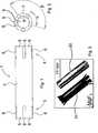
Die
Der Stent
Die
Wie in den
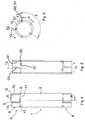
Der Stent
Die
Die
Die
Die
Die
Die
Gemäß
Die
Die
ZITATE ENTHALTEN IN DER BESCHREIBUNG QUOTES INCLUDE IN THE DESCRIPTION
Diese Liste der vom Anmelder aufgeführten Dokumente wurde automatisiert erzeugt und ist ausschließlich zur besseren Information des Lesers aufgenommen. Die Liste ist nicht Bestandteil der deutschen Patent- bzw. Gebrauchsmusteranmeldung. Das DPMA übernimmt keinerlei Haftung für etwaige Fehler oder Auslassungen.This list of the documents listed by the applicant has been generated automatically and is included solely for the better information of the reader. The list is not part of the German patent or utility model application. The DPMA assumes no liability for any errors or omissions.
Zitierte PatentliteraturCited patent literature
- US 5601594[0004]US 5601594[0004]
Claims (13)
Translated fromGermanPriority Applications (3)
| Application Number | Priority Date | Filing Date | Title |
|---|---|---|---|
| DE201010044438DE102010044438A1 (en) | 2010-09-06 | 2010-09-06 | Stent and process for its production |
| EP11755012.9AEP2613736B1 (en) | 2010-09-06 | 2011-09-06 | Stent and method for the production thereof |
| PCT/EP2011/004472WO2012031737A1 (en) | 2010-09-06 | 2011-09-06 | Stent and method for the production thereof |
Applications Claiming Priority (1)
| Application Number | Priority Date | Filing Date | Title |
|---|---|---|---|
| DE201010044438DE102010044438A1 (en) | 2010-09-06 | 2010-09-06 | Stent and process for its production |
Publications (1)
| Publication Number | Publication Date |
|---|---|
| DE102010044438A1true DE102010044438A1 (en) | 2012-03-08 |
Family
ID=44645063
Family Applications (1)
| Application Number | Title | Priority Date | Filing Date |
|---|---|---|---|
| DE201010044438CeasedDE102010044438A1 (en) | 2010-09-06 | 2010-09-06 | Stent and process for its production |
Country Status (3)
| Country | Link |
|---|---|
| EP (1) | EP2613736B1 (en) |
| DE (1) | DE102010044438A1 (en) |
| WO (1) | WO2012031737A1 (en) |
Citations (9)
| Publication number | Priority date | Publication date | Assignee | Title |
|---|---|---|---|---|
| US5601594A (en) | 1995-09-14 | 1997-02-11 | Best; Barry D. | Nasal stent |
| US5868777A (en)* | 1993-12-02 | 1999-02-09 | Advanced Cardiovascular Systems, Inc. | Method for repairing a bifurcated vessel |
| WO2006083991A2 (en)* | 2005-02-04 | 2006-08-10 | Poly-Med, Inc. | Fiber-reinforced composite absorbable endoureteral stent |
| DE102005016103A1 (en)* | 2005-04-08 | 2006-10-19 | Alveolus Inc. | Duodenum surgical stent implant has rigid constructed center section located between rigid distal sections |
| DE102006009996A1 (en)* | 2006-03-03 | 2007-09-06 | Albrecht Dr. Elsässer | stent |
| US20070282422A1 (en)* | 2006-05-10 | 2007-12-06 | Cook Incorporated | Medical devices and methods for local delivery of elastin-stabilizing compounds |
| US20070292478A1 (en)* | 2004-08-30 | 2007-12-20 | Popowski Youri | Medical Implant Provided with Inhibitors of Atp Synthesis |
| US20080082162A1 (en)* | 2006-09-15 | 2008-04-03 | Boston Scientific Scimed, Inc. | Bioerodible endoprostheses and methods of making the same |
| US20090182404A1 (en)* | 2008-01-10 | 2009-07-16 | Shokoohi Mehrdad M | Biodegradable self-expanding drug-eluting prosthesis |
Family Cites Families (2)
| Publication number | Priority date | Publication date | Assignee | Title |
|---|---|---|---|---|
| US20080294255A1 (en)* | 2006-05-23 | 2008-11-27 | Donald Albert Gonzales | Sinus Tube |
| EP3791826B1 (en)* | 2007-12-18 | 2025-01-29 | Intersect ENT, Inc. | Self-expanding devices |
- 2010
- 2010-09-06DEDE201010044438patent/DE102010044438A1/ennot_activeCeased
- 2011
- 2011-09-06EPEP11755012.9Apatent/EP2613736B1/ennot_activeNot-in-force
- 2011-09-06WOPCT/EP2011/004472patent/WO2012031737A1/enactiveApplication Filing
Patent Citations (9)
| Publication number | Priority date | Publication date | Assignee | Title |
|---|---|---|---|---|
| US5868777A (en)* | 1993-12-02 | 1999-02-09 | Advanced Cardiovascular Systems, Inc. | Method for repairing a bifurcated vessel |
| US5601594A (en) | 1995-09-14 | 1997-02-11 | Best; Barry D. | Nasal stent |
| US20070292478A1 (en)* | 2004-08-30 | 2007-12-20 | Popowski Youri | Medical Implant Provided with Inhibitors of Atp Synthesis |
| WO2006083991A2 (en)* | 2005-02-04 | 2006-08-10 | Poly-Med, Inc. | Fiber-reinforced composite absorbable endoureteral stent |
| DE102005016103A1 (en)* | 2005-04-08 | 2006-10-19 | Alveolus Inc. | Duodenum surgical stent implant has rigid constructed center section located between rigid distal sections |
| DE102006009996A1 (en)* | 2006-03-03 | 2007-09-06 | Albrecht Dr. Elsässer | stent |
| US20070282422A1 (en)* | 2006-05-10 | 2007-12-06 | Cook Incorporated | Medical devices and methods for local delivery of elastin-stabilizing compounds |
| US20080082162A1 (en)* | 2006-09-15 | 2008-04-03 | Boston Scientific Scimed, Inc. | Bioerodible endoprostheses and methods of making the same |
| US20090182404A1 (en)* | 2008-01-10 | 2009-07-16 | Shokoohi Mehrdad M | Biodegradable self-expanding drug-eluting prosthesis |
Also Published As
| Publication number | Publication date |
|---|---|
| EP2613736A1 (en) | 2013-07-17 |
| WO2012031737A1 (en) | 2012-03-15 |
| EP2613736B1 (en) | 2014-11-26 |
Similar Documents
| Publication | Publication Date | Title |
|---|---|---|
| DE69729633T2 (en) | IMPLANTABLE DEVICE FOR SUSTAINING OR RESTORING A NORMAL BODY VESSEL CROSS SECTION | |
| EP2257248B1 (en) | Stent and method for the production of such a stent | |
| EP2145585B1 (en) | Puncture seal for sealing a hollow organ with a puncture opening, in particular a blood vessel | |
| EP3423148B1 (en) | Implantable cuff electrode | |
| DE29708803U1 (en) | Radially expandable stent for implantation in a body vessel in the area of a vascular branch | |
| DE102008013948A1 (en) | Catheter for removably receiving e.g. heart valve supporting stent, has controlling device controlling expanding and unfolding of implant from diameter to another diameter and retraction of implant from latter diameter to former diameter | |
| EP0800800A1 (en) | Stent for transluminal implantation in a hollow organ | |
| DE19740506A1 (en) | Stent with variable features to optimize the support properties and method for producing such a stent | |
| DE102016110199A1 (en) | Vasospasmusbehandlung | |
| DE102005039136B4 (en) | Improving the radiopacity and corrosion resistance of NiTi stents using sandwiched rivets | |
| EP2628468A1 (en) | Medical device | |
| AT411328B (en) | TUBE SYSTEM FOR THE RECONSTRUCTION OF A URINE TUBE | |
| EP1649889B1 (en) | Catheter particularly for insertion of pace-maker or ICD-electrodes into a patient's body | |
| EP1970088B1 (en) | Catheter with sections with changeable volume | |
| EP2613736B1 (en) | Stent and method for the production thereof | |
| EP3073935B1 (en) | System for connecting a medical implant to an insertion aid | |
| DE102020006503A1 (en) | Endoluminal closure device, medical system and method for treatment of lung disease | |
| EP2726027B1 (en) | Body implant with improved x-ray visibility, and method for producing same | |
| DE102010028705A1 (en) | Tympanic membrane implant i.e. tympanostomy tube, for ventilation of tympanic cavity of patient during e.g. middle ear effusions, has small tube provided with outer flange between end-sided flange and end of through-hole | |
| DE102009033464A1 (en) | Device and system for aeration of the middle ear | |
| WO1998018404A1 (en) | Stent | |
| EP3781088B1 (en) | Device for introducing implants | |
| DE202009017418U1 (en) | Medical implant for closing vascular openings | |
| EP4257088A1 (en) | Implant system for the treatment of bone defects or imperfections | |
| DE102023107682A1 (en) | Mounting aid for positioning a probe in an application cap |
Legal Events
| Date | Code | Title | Description |
|---|---|---|---|
| R082 | Change of representative | Representative=s name:GRAMM, LINS & PARTNER GBR, DE Representative=s name:GRAMM, LINS & PARTNER GBR, 30173 HANNOVER, DE | |
| R016 | Response to examination communication | ||
| R081 | Change of applicant/patentee | Owner name:STIFTUNG TIERAERZTLICHE HOCHSCHULE HANNOVER, DE Free format text:FORMER OWNERS: GOTTFRIED WILHELM LEIBNIZ UNIVERSITAET HANNOVER, 30167 HANNOVER, DE; MEDIZINISCHE HOCHSCHULE HANNOVER, 30625 HANNOVER, DE Effective date:20120208 Owner name:MEDIZINISCHE HOCHSCHULE HANNOVER, DE Free format text:FORMER OWNERS: GOTTFRIED WILHELM LEIBNIZ UNIVERSITAET HANNOVER, 30167 HANNOVER, DE; MEDIZINISCHE HOCHSCHULE HANNOVER, 30625 HANNOVER, DE Effective date:20120208 Owner name:GOTTFRIED WILHELM LEIBNIZ UNIVERSITAET HANNOVE, DE Free format text:FORMER OWNERS: GOTTFRIED WILHELM LEIBNIZ UNIVERSITAET HANNOVER, 30167 HANNOVER, DE; MEDIZINISCHE HOCHSCHULE HANNOVER, 30625 HANNOVER, DE Effective date:20120208 Owner name:GOTTFRIED WILHELM LEIBNIZ UNIVERSITAET HANNOVE, DE Free format text:FORMER OWNER: GOTTFRIED WILHELM LEIBNIZ UNIVERSITAET HANNOVER, 30167 HANNOVER, DE Effective date:20110908 Owner name:STIFTUNG TIERAERZTLICHE HOCHSCHULE HANNOVER, DE Free format text:FORMER OWNER: GOTTFRIED WILHELM LEIBNIZ UNIVERSITAET HANNOVER, 30167 HANNOVER, DE Effective date:20110908 Owner name:MEDIZINISCHE HOCHSCHULE HANNOVER, DE Free format text:FORMER OWNER: GOTTFRIED WILHELM LEIBNIZ UNIVERSITAET HANNOVER, 30167 HANNOVER, DE Effective date:20110908 Owner name:STIFTUNG TIERAERZTLICHE HOCHSCHULE HANNOVER, DE Free format text:FORMER OWNER: GOTTFRIED WILHELM LEIBNIZ UNIVE, MEDIZINISCHE HOCHSCHULE HANNOVE, , DE Effective date:20120208 Owner name:MEDIZINISCHE HOCHSCHULE HANNOVER, DE Free format text:FORMER OWNER: GOTTFRIED WILHELM LEIBNIZ UNIVE, MEDIZINISCHE HOCHSCHULE HANNOVE, , DE Effective date:20120208 Owner name:GOTTFRIED WILHELM LEIBNIZ UNIVERSITAET HANNOVE, DE Free format text:FORMER OWNER: GOTTFRIED WILHELM LEIBNIZ UNIVE, MEDIZINISCHE HOCHSCHULE HANNOVE, , DE Effective date:20120208 | |
| R082 | Change of representative | Representative=s name:GRAMM, LINS & PARTNER PATENT- UND RECHTSANWAEL, DE Effective date:20120208 Representative=s name:GRAMM, LINS & PARTNER PATENT- UND RECHTSANWAEL, DE Effective date:20110908 Representative=s name:GRAMM, LINS & PARTNER GBR, DE Effective date:20110908 Representative=s name:GRAMM, LINS & PARTNER GBR, DE Effective date:20120208 Representative=s name:GRAMM, LINS & PARTNER GBR, 30173 HANNOVER, DE | |
| R079 | Amendment of ipc main class | Free format text:PREVIOUS MAIN CLASS: A61F0002040000 Ipc:A61F0002820000 Effective date:20121227 | |
| R082 | Change of representative | Representative=s name:GRAMM, LINS & PARTNER PATENT- UND RECHTSANWAEL, DE | |
| R002 | Refusal decision in examination/registration proceedings | ||
| R003 | Refusal decision now final |