DE102010044327A1 - Zentrierspannvorrichtung - Google Patents
ZentrierspannvorrichtungDownload PDFInfo
- Publication number
- DE102010044327A1 DE102010044327A1DE201010044327DE102010044327ADE102010044327A1DE 102010044327 A1DE102010044327 A1DE 102010044327A1DE 201010044327DE201010044327DE 201010044327DE 102010044327 ADE102010044327 ADE 102010044327ADE 102010044327 A1DE102010044327 A1DE 102010044327A1
- Authority
- DE
- Germany
- Prior art keywords
- opening
- housing
- sealing element
- clamping device
- hook
- Prior art date
- Legal status (The legal status is an assumption and is not a legal conclusion. Google has not performed a legal analysis and makes no representation as to the accuracy of the status listed.)
- Withdrawn
Links
- 238000007789sealingMethods0.000claimsabstractdescription39
- 238000010408sweepingMethods0.000claimsabstractdescription3
- 230000033001locomotionEffects0.000description5
- 230000015572biosynthetic processEffects0.000description2
- 230000001419dependent effectEffects0.000description2
- 238000011161developmentMethods0.000description2
- 230000018109developmental processEffects0.000description2
- BUHVIAUBTBOHAG-FOYDDCNASA-N(2r,3r,4s,5r)-2-[6-[[2-(3,5-dimethoxyphenyl)-2-(2-methylphenyl)ethyl]amino]purin-9-yl]-5-(hydroxymethyl)oxolane-3,4-diolChemical compoundCOC1=CC(OC)=CC(C(CNC=2C=3N=CN(C=3N=CN=2)[C@H]2[C@@H]([C@H](O)[C@@H](CO)O2)O)C=2C(=CC=CC=2)C)=C1BUHVIAUBTBOHAG-FOYDDCNASA-N0.000description1
- 238000011109contaminationMethods0.000description1
- 239000012535impuritySubstances0.000description1
- 239000002184metalSubstances0.000description1
Images


Classifications
- B—PERFORMING OPERATIONS; TRANSPORTING
- B25—HAND TOOLS; PORTABLE POWER-DRIVEN TOOLS; MANIPULATORS
- B25B—TOOLS OR BENCH DEVICES NOT OTHERWISE PROVIDED FOR, FOR FASTENING, CONNECTING, DISENGAGING OR HOLDING
- B25B5/00—Clamps
- B25B5/06—Arrangements for positively actuating jaws
- B25B5/061—Arrangements for positively actuating jaws with fluid drive
- B25B5/062—Arrangements for positively actuating jaws with fluid drive with clamping means pivoting around an axis parallel to the pressing direction
- B—PERFORMING OPERATIONS; TRANSPORTING
- B25—HAND TOOLS; PORTABLE POWER-DRIVEN TOOLS; MANIPULATORS
- B25B—TOOLS OR BENCH DEVICES NOT OTHERWISE PROVIDED FOR, FOR FASTENING, CONNECTING, DISENGAGING OR HOLDING
- B25B5/00—Clamps
- B25B5/06—Arrangements for positively actuating jaws
- B25B5/08—Arrangements for positively actuating jaws using cams
- B25B5/087—Arrangements for positively actuating jaws using cams actuated by a hydraulic or pneumatic piston
- B—PERFORMING OPERATIONS; TRANSPORTING
- B25—HAND TOOLS; PORTABLE POWER-DRIVEN TOOLS; MANIPULATORS
- B25B—TOOLS OR BENCH DEVICES NOT OTHERWISE PROVIDED FOR, FOR FASTENING, CONNECTING, DISENGAGING OR HOLDING
- B25B5/00—Clamps
- B25B5/06—Arrangements for positively actuating jaws
- B25B5/12—Arrangements for positively actuating jaws using toggle links
- B25B5/122—Arrangements for positively actuating jaws using toggle links with fluid drive
Landscapes
- Engineering & Computer Science (AREA)
- Mechanical Engineering (AREA)
- Clamps And Clips (AREA)
- Hooks, Suction Cups, And Attachment By Adhesive Means (AREA)
Abstract
Translated fromGermanDescription
Translated fromGermanDie Erfindung betrifft eine Zentrierspannvorrichtung gemäß dem Oberbegriff des Patentanspruchs 1.The invention relates to a centering clamping device according to the preamble of patent claim 1.
Eine Zentrierspannvorrichtung der eingangs genannten Art ist nach der
Der Erfindung liegt daher die Aufgabe zugrunde, eine Zentrierspannvorrichtung der eingangs genannten Art zu verbessern, und zwar insbesondere unter dem Aspekt, dass das Innere des Gehäuses noch besser vor Verunreinigungen als beim genannten Stand der Technik geschützt ist.The invention is therefore based on the object to improve a Zentrierspannvorrichtung of the type mentioned, in particular from the aspect that the interior of the housing is even better protected from contamination than the cited prior art.
Diese Aufgabe ist mit einer Zentrierspannvorrichtung der eingangs genannten Art durch die im Kennzeichen des Patentanspruchs 1 aufgeführten Merkmale gelöst.This object is achieved with a Zentrierspannvorrichtung of the type mentioned by the features listed in the characterizing part of claim 1.
Nach der Erfindung ist also vorgesehen, dass das mit einer in jeder Stellung zum Spannhaken passgenauen Durchgriffsöffnung für den Spannhaken versehene Abdichtelement in der Öffnung des Gehäuses drehbar gelagert und die Öffnung des Gehäuses in jeder Drehposition des Abdichtelements vollständig verschließend ausgebildet ist.According to the invention, it is thus provided that the sealing element provided with a through-hole suitable for the clamping hook for the clamping hook is rotatably mounted in the opening of the housing and the opening of the housing is completely occlusive in each rotational position of the sealing element.
Mit anderen Worten ist erfindungsgemäß statt des Schlitzabdeckschiebers ein Abdichtelement vorgesehen, das innerhalb der Öffnung drehbar gelagert ist und seinerseits eine Durchgriffsöffnung für den Spannhaken aufweist. Die prinzipiell erforderliche Beweglichkeit des Spannhakens in zwei Raumrichtungen wird damit nicht mehr über die Öffnung selbst erreicht, sondern dadurch, dass der Spannhaken einerseits axialverschieblich im Abdichtelement geführt ist und andererseits dadurch, dass das Abdichtelement selbst innerhalb der Öffnung drehbar gelagert ist. Auf diese Weise entfällt die mit dem Schlitzabdeckschieber zu verschließende Öffnung, wobei weiterhin durch die Aufspaltung der Bewegungsführungen die jeweilige Abdichtung vereinfacht wird. Der Spannhaken selbst ist, wie erwähnt, lediglich axial verstellbar in der Durchgriffsöffnung geführt, d. h. hier genügt es zur Gewährleistung der Dichtigkeit, dafür zu sorgen, dass der Querschnitt des Spannhakens auf der gesamten Stellwegslänge dem Querschnitt der Durchgriffsöffnung entspricht. Bezüglich der Verdrehbarkeit des Abdichtelements zum Gehäuse führt zum Beispiel bereits eine etwa zylinderförmige Ausbildung des Abdichtelements zum gewünschten Ergebnis, nämlich einer sicheren Abdichtung der Öffnung des Gehäuses.In other words, instead of the Schlitzabdeckschiebers a sealing element according to the invention is provided which is rotatably mounted within the opening and in turn has a passage opening for the clamping hook. The principle required mobility of the clamping hook in two spatial directions is thus no longer achieved through the opening itself, but in that the clamping hook is guided on the one hand axially displaceable in the sealing element and on the other hand, characterized in that the sealing element is rotatably supported even within the opening. In this way, eliminates the opening to be closed with the Schlitzabdeckschieber, which further simplifies the respective seal by splitting the motion guides. The clamping hook itself is, as mentioned, only axially adjustable guided in the passage opening, d. H. Here it is sufficient to ensure the tightness, to ensure that the cross section of the clamping hook on the entire travel path corresponds to the cross section of the passage opening. With regard to the rotatability of the sealing element to the housing, for example, an approximately cylindrical design of the sealing element already leads to the desired result, namely a secure sealing of the opening of the housing.
Andere vorteilhafte Weiterbildungen ergeben sich aus den abhängigen Patentansprüchen.Other advantageous developments emerge from the dependent claims.
Die erfindungsgemäße Zentrierspannvorrichtung einschließlich ihrer vorteilhaften Weiterbildungen gemäß der abhängigen Patentansprüche wird nachfolgend anhand der zeichnerischen Darstellung eines bevorzugten Ausführungsbeispiels näher erläutert.The Zentrierspannvorrichtung invention including its advantageous developments according to the dependent claims will be explained in more detail with reference to the drawing of a preferred embodiment.
Es zeigtIt shows
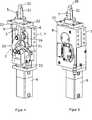
Die in den
Dabei ist am spannhakenabgewandten Ende des Gehäuses
Wesentlich ist nun, dass das mit einer in jeder Stellung zum Spannhaken
Wie eingangs erläutert, hat diese erfindungsgemäße Maßgabe zur Folge, dass über die (beim Stand der Technik lediglich mit einem Schlitzabdeckschieber verschließbare) Öffnung
Besonders bevorzugt ist dabei wie dargestellt vorgesehen, dass das Abdichtelement
Damit sich zwischen dem Abdichtelement
Außerdem ist insbesondere mit Verweis auf
Weiterhin ist vorgesehen, dass der Spannhaken
Wie insbesondere aus
Im Vergleich zur vorgenannten
Weiterhin ist außen am Gehäuse
Die erfindungsgemäße Zentrierspannvorrichtung funktioniert, wie folgt: In
BezugszeichenlisteLIST OF REFERENCE NUMBERS
- 11
- Gehäusecasing
- 22
- Antriebsmechanikdrive mechanism
- 33
- Abdichtelementsealing
- 44
- Öffnungopening
- 55
- Spannhakententerhook
- 66
- DurchgriffsöffnungThrough opening
- 77
- Halbschalehalf shell
- 88th
- Halbschalehalf shell
- 99
- Antriebselementdriving element
- 1010
- Stellstangecontrol rod
- 1111
- Hebellever
- 1212
- Schleppglieddrag link
- 1313
- Schlitzführungslot guide
- 1414
- Hebelarmlever arm
- 1515
- Hebelarmlever arm
- 1616
- Führungszapfenspigot
- 1717
- Führungsnutguide
- 1818
- Führungsabschnittguide section
- 1919
- Führungsabschnittguide section
- 2020
- Zentrierdorncentering
- 2121
- Aufnahmebereichreception area
- 2222
- Adapterplatteadapter plate
- 2323
- Ausnehmungrecess
ZITATE ENTHALTEN IN DER BESCHREIBUNG QUOTES INCLUDE IN THE DESCRIPTION
Diese Liste der vom Anmelder aufgeführten Dokumente wurde automatisiert erzeugt und ist ausschließlich zur besseren Information des Lesers aufgenommen. Die Liste ist nicht Bestandteil der deutschen Patent- bzw. Gebrauchsmusteranmeldung. Das DPMA übernimmt keinerlei Haftung für etwaige Fehler oder Auslassungen.This list of the documents listed by the applicant has been generated automatically and is included solely for the better information of the reader. The list is not part of the German patent or utility model application. The DPMA assumes no liability for any errors or omissions.
Zitierte PatentliteraturCited patent literature
- DE 10238815 B3[0002, 0024]DE 10238815 B3[0002, 0024]
Claims (10)
Translated fromGermanPriority Applications (11)
| Application Number | Priority Date | Filing Date | Title |
|---|---|---|---|
| DE201010044327DE102010044327A1 (en) | 2010-09-03 | 2010-09-03 | Zentrierspannvorrichtung |
| EP11179135AEP2425929A1 (en) | 2010-09-03 | 2011-08-29 | Centring clamping device |
| PL11774124TPL2611577T3 (en) | 2010-09-03 | 2011-09-01 | Centering and clamping device |
| PCT/US2011/050125WO2012031062A1 (en) | 2010-09-03 | 2011-09-01 | Centering and clamping device |
| US13/223,352US8967604B2 (en) | 2010-09-03 | 2011-09-01 | Centering and clamping device |
| MX2013002542AMX2013002542A (en) | 2010-09-03 | 2011-09-01 | Centering and clamping device. |
| CN201180044785.7ACN103140328B (en) | 2010-09-03 | 2011-09-01 | Center and clamping device |
| EP11774124.9AEP2611577B1 (en) | 2010-09-03 | 2011-09-01 | Centering and clamping device |
| ES11774124TES2713483T3 (en) | 2010-09-03 | 2011-09-01 | Centering and clamping device |
| CA2810214ACA2810214C (en) | 2010-09-03 | 2011-09-01 | Centering and clamping device |
| BR112013005244ABR112013005244A2 (en) | 2010-09-03 | 2011-09-01 | clamping and centering device |
Applications Claiming Priority (1)
| Application Number | Priority Date | Filing Date | Title |
|---|---|---|---|
| DE201010044327DE102010044327A1 (en) | 2010-09-03 | 2010-09-03 | Zentrierspannvorrichtung |
Publications (1)
| Publication Number | Publication Date |
|---|---|
| DE102010044327A1true DE102010044327A1 (en) | 2012-03-08 |
Family
ID=44720601
Family Applications (1)
| Application Number | Title | Priority Date | Filing Date |
|---|---|---|---|
| DE201010044327WithdrawnDE102010044327A1 (en) | 2010-09-03 | 2010-09-03 | Zentrierspannvorrichtung |
Country Status (10)
| Country | Link |
|---|---|
| US (1) | US8967604B2 (en) |
| EP (2) | EP2425929A1 (en) |
| CN (1) | CN103140328B (en) |
| BR (1) | BR112013005244A2 (en) |
| CA (1) | CA2810214C (en) |
| DE (1) | DE102010044327A1 (en) |
| ES (1) | ES2713483T3 (en) |
| MX (1) | MX2013002542A (en) |
| PL (1) | PL2611577T3 (en) |
| WO (1) | WO2012031062A1 (en) |
Cited By (1)
| Publication number | Priority date | Publication date | Assignee | Title |
|---|---|---|---|---|
| DE102010046190A1 (en) | 2010-09-23 | 2012-03-29 | De-Sta-Co Europe Gmbh | Zentrierspannvorrichtung |
Families Citing this family (10)
| Publication number | Priority date | Publication date | Assignee | Title |
|---|---|---|---|---|
| US10052744B2 (en)* | 2011-01-10 | 2018-08-21 | GM Global Technology Operations LLC | Fixture for supporting a workpiece |
| US10625382B2 (en) | 2012-08-01 | 2020-04-21 | Delaware Capital Formation, Inc. | Toggle lever clamp |
| WO2015039099A1 (en)* | 2013-09-16 | 2015-03-19 | Huntington Ingalls, Inc. | Locking device |
| US8950741B1 (en)* | 2014-03-03 | 2015-02-10 | Praxis Industries, Llc | Clamping assembly |
| DE102014109897A1 (en)* | 2014-07-15 | 2016-01-21 | De-Sta-Co Europe Gmbh | jig |
| US9770810B2 (en)* | 2014-11-12 | 2017-09-26 | De-Sta-Co Europe Gmbh | Pin clamp |
| US20180015580A1 (en)* | 2016-07-15 | 2018-01-18 | Tech Rim Standards, LLC | Adjustable pin clamping device |
| WO2020243083A1 (en)* | 2019-05-24 | 2020-12-03 | Swan Christopher A | Modular clamping system |
| FR3097796A1 (en)* | 2019-06-25 | 2021-01-01 | Sidel Participations | Hollow body heating unit for plastic container manufacturing machine |
| US11759915B2 (en) | 2021-10-03 | 2023-09-19 | Delaware Capital Formation, Inc. | Pneumatic latch clamp |
Citations (3)
| Publication number | Priority date | Publication date | Assignee | Title |
|---|---|---|---|---|
| EP0937538A1 (en)* | 1998-02-18 | 1999-08-25 | Delaware Capital Formation, Inc. | Low profile pneumatic retractor clamp |
| DE10238815B3 (en) | 2002-08-23 | 2004-02-26 | De-Sta-Co Metallerzeugnisse Gmbh | Centering |
| US20050017424A1 (en)* | 2003-07-24 | 2005-01-27 | Univer S.P.A. | Toggle-lever clamping device for clamping work pieces with self-compensation |
Family Cites Families (14)
| Publication number | Priority date | Publication date | Assignee | Title |
|---|---|---|---|---|
| US3578306A (en)* | 1969-06-05 | 1971-05-11 | Kenneth C Smith | Air pressure operated clamp |
| DE3531766C1 (en)* | 1985-09-06 | 1989-07-20 | Honsberg Gmbh Geb | Clamping device for workpieces |
| DE19531889A1 (en)* | 1995-08-30 | 1997-03-06 | Rudolf Kohlert | Clamping element |
| US6105947A (en)* | 1996-08-28 | 2000-08-22 | Delaware Capital Formation, Inc. | Low profile pneumatic retractor clamp |
| US5752693A (en)* | 1996-08-30 | 1998-05-19 | Vektek, Inc. | Retract clamp apparatus |
| ITMI20021756A1 (en)* | 2002-08-02 | 2004-02-03 | Luciano Migliori | HOOKING DEVICE FOR WORKPIECES. |
| ITMI20030270A1 (en)* | 2003-02-14 | 2004-08-15 | Univer Spa | HOOKING DEVICE FOR WORKPIECES. |
| US6931980B1 (en)* | 2003-03-21 | 2005-08-23 | Zaytran, Inc. | Pneumatic device with cushioning mechanism |
| JP3941059B2 (en)* | 2003-07-01 | 2007-07-04 | Smc株式会社 | Locate clamp device |
| ITMI20031454A1 (en)* | 2003-07-16 | 2005-01-17 | Univer Spa | COMPACT BINDING DEVICE FOR WORK PIECES |
| US7144002B2 (en)* | 2004-06-08 | 2006-12-05 | Smc Corporation | Electric locking device |
| US7311301B2 (en)* | 2004-08-03 | 2007-12-25 | Delaware Capital Formation, Inc. | Hook pin unit having weld slag protection |
| US7669840B2 (en)* | 2005-01-25 | 2010-03-02 | Delaware Capital Formation, Inc. | Hook clamp unit |
| DE102006042656B4 (en)* | 2006-09-12 | 2010-11-18 | Hans-Joachim Bauer | Clamping device with retractable clamping arm |
- 2010
- 2010-09-03DEDE201010044327patent/DE102010044327A1/ennot_activeWithdrawn
- 2011
- 2011-08-29EPEP11179135Apatent/EP2425929A1/ennot_activeWithdrawn
- 2011-09-01CNCN201180044785.7Apatent/CN103140328B/enactiveActive
- 2011-09-01MXMX2013002542Apatent/MX2013002542A/enactiveIP Right Grant
- 2011-09-01ESES11774124Tpatent/ES2713483T3/enactiveActive
- 2011-09-01CACA2810214Apatent/CA2810214C/ennot_activeExpired - Fee Related
- 2011-09-01EPEP11774124.9Apatent/EP2611577B1/ennot_activeNot-in-force
- 2011-09-01BRBR112013005244Apatent/BR112013005244A2/ennot_activeApplication Discontinuation
- 2011-09-01WOPCT/US2011/050125patent/WO2012031062A1/enactiveApplication Filing
- 2011-09-01USUS13/223,352patent/US8967604B2/enactiveActive
- 2011-09-01PLPL11774124Tpatent/PL2611577T3/enunknown
Patent Citations (3)
| Publication number | Priority date | Publication date | Assignee | Title |
|---|---|---|---|---|
| EP0937538A1 (en)* | 1998-02-18 | 1999-08-25 | Delaware Capital Formation, Inc. | Low profile pneumatic retractor clamp |
| DE10238815B3 (en) | 2002-08-23 | 2004-02-26 | De-Sta-Co Metallerzeugnisse Gmbh | Centering |
| US20050017424A1 (en)* | 2003-07-24 | 2005-01-27 | Univer S.P.A. | Toggle-lever clamping device for clamping work pieces with self-compensation |
Cited By (2)
| Publication number | Priority date | Publication date | Assignee | Title |
|---|---|---|---|---|
| DE102010046190A1 (en) | 2010-09-23 | 2012-03-29 | De-Sta-Co Europe Gmbh | Zentrierspannvorrichtung |
| DE102010046190B4 (en) | 2010-09-23 | 2019-02-21 | Destaco Europe Gmbh | Zentrierspannvorrichtung with elastically mounted in the housing lever element |
Also Published As
| Publication number | Publication date |
|---|---|
| ES2713483T3 (en) | 2019-05-22 |
| EP2425929A1 (en) | 2012-03-07 |
| CN103140328A (en) | 2013-06-05 |
| BR112013005244A2 (en) | 2018-05-02 |
| PL2611577T3 (en) | 2019-05-31 |
| EP2611577A1 (en) | 2013-07-10 |
| US20120056384A1 (en) | 2012-03-08 |
| MX2013002542A (en) | 2013-06-28 |
| CA2810214C (en) | 2019-01-29 |
| EP2611577B1 (en) | 2019-01-09 |
| CN103140328B (en) | 2016-06-01 |
| CA2810214A1 (en) | 2012-03-08 |
| US8967604B2 (en) | 2015-03-03 |
| WO2012031062A1 (en) | 2012-03-08 |
Similar Documents
| Publication | Publication Date | Title |
|---|---|---|
| DE102010044327A1 (en) | Zentrierspannvorrichtung | |
| EP2913162B1 (en) | Line retraction system | |
| EP0313767B1 (en) | Clamping device | |
| AT511587B1 (en) | MOVABLE MOUNTING PLATE FOR FURNITURE HINGES | |
| DE102010046190A1 (en) | Zentrierspannvorrichtung | |
| EP2576152B1 (en) | Device holder | |
| EP1564360B1 (en) | Device for the motorized opening and closing of a vehicle body element | |
| DE102010000340A1 (en) | Feeding device for sliding doors | |
| DE202014100931U1 (en) | Line retraction system | |
| DE9016781U1 (en) | Clamping device | |
| DE202017100850U1 (en) | Brake fitting for a flap that opens at the bottom | |
| EP0436883B1 (en) | Clamping device | |
| EP0597193A2 (en) | Pipe clamp | |
| EP2894265A1 (en) | Pneumatic actuation device | |
| EP2433751A2 (en) | Centring clamping device | |
| DE102013002905B3 (en) | Manually operable forming machine i.e. bending machine, has lifting device comprising manually pivotable operating lever that is movable between closed position and maximum opening position | |
| DE2605697A1 (en) | DOOR LOCKING DEVICE | |
| EP0502254A1 (en) | Reversible device for working between plants | |
| DE1179692B (en) | Sealing device for doors | |
| DE102014109897A1 (en) | jig | |
| DE202023106904U1 (en) | Container and device for power-assisted opening of a door of the container | |
| DE102007059080B4 (en) | Device for cleaning hand tools used in meat processing | |
| DE102015117480A1 (en) | presentation device | |
| DE102011056851A1 (en) | tongs | |
| DE4000888A1 (en) | Quick-acting coupling esp. for suction cleaner tubes - relies upon clamping of inner telescopic section within sleeve by pressure from end of hand lever |
Legal Events
| Date | Code | Title | Description |
|---|---|---|---|
| R082 | Change of representative | Representative=s name:WOLF & WOLF PATENT- UND RECHTSANWALTSGESELLSCH, DE Representative=s name:WOLF & WOLF PATENT- UND RECHTSANWAELTE GBR, DE Representative=s name:WOLF & WOLF PATENT- UND RECHTSANWAELTE, DE | |
| R081 | Change of applicant/patentee | Owner name:DESTACO EUROPE GMBH, DE Free format text:FORMER OWNER: DE-STA-CO EUROPE GMBH, 61440 OBERURSEL, DE | |
| R082 | Change of representative | Representative=s name:WOLF & WOLF PATENT- UND RECHTSANWALTSGESELLSCH, DE | |
| R119 | Application deemed withdrawn, or ip right lapsed, due to non-payment of renewal fee |