DE102010041352A1 - Hand-held power tool with a suction adapter - Google Patents
Hand-held power tool with a suction adapterDownload PDFInfo
- Publication number
- DE102010041352A1 DE102010041352A1DE201010041352DE102010041352ADE102010041352A1DE 102010041352 A1DE102010041352 A1DE 102010041352A1DE 201010041352DE201010041352DE 201010041352DE 102010041352 ADE102010041352 ADE 102010041352ADE 102010041352 A1DE102010041352 A1DE 102010041352A1
- Authority
- DE
- Germany
- Prior art keywords
- suction
- protective cover
- power tool
- outlet opening
- suction adapter
- Prior art date
- Legal status (The legal status is an assumption and is not a legal conclusion. Google has not performed a legal analysis and makes no representation as to the accuracy of the status listed.)
- Ceased
Links
- 230000001681protective effectEffects0.000claimsabstractdescription40
- 239000000463materialSubstances0.000claimsabstractdescription18
- 230000001960triggered effectEffects0.000abstractdescription2
- 208000027418Wounds and injuryDiseases0.000description1
- 238000007792additionMethods0.000description1
- 239000007767bonding agentSubstances0.000description1
- 238000010276constructionMethods0.000description1
- 230000006378damageEffects0.000description1
- 230000001419dependent effectEffects0.000description1
- 238000006073displacement reactionMethods0.000description1
- 208000014674injuryDiseases0.000description1
- 238000003754machiningMethods0.000description1
- 238000012986modificationMethods0.000description1
- 230000004048modificationEffects0.000description1
- 230000001105regulatory effectEffects0.000description1
Images


Classifications
- B—PERFORMING OPERATIONS; TRANSPORTING
- B23—MACHINE TOOLS; METAL-WORKING NOT OTHERWISE PROVIDED FOR
- B23Q—DETAILS, COMPONENTS, OR ACCESSORIES FOR MACHINE TOOLS, e.g. ARRANGEMENTS FOR COPYING OR CONTROLLING; MACHINE TOOLS IN GENERAL CHARACTERISED BY THE CONSTRUCTION OF PARTICULAR DETAILS OR COMPONENTS; COMBINATIONS OR ASSOCIATIONS OF METAL-WORKING MACHINES, NOT DIRECTED TO A PARTICULAR RESULT
- B23Q11/00—Accessories fitted to machine tools for keeping tools or parts of the machine in good working condition or for cooling work; Safety devices specially combined with or arranged in, or specially adapted for use in connection with, machine tools
- B23Q11/0042—Devices for removing chips
- B23Q11/0046—Devices for removing chips by sucking
- B—PERFORMING OPERATIONS; TRANSPORTING
- B23—MACHINE TOOLS; METAL-WORKING NOT OTHERWISE PROVIDED FOR
- B23D—PLANING; SLOTTING; SHEARING; BROACHING; SAWING; FILING; SCRAPING; LIKE OPERATIONS FOR WORKING METAL BY REMOVING MATERIAL, NOT OTHERWISE PROVIDED FOR
- B23D59/00—Accessories specially designed for sawing machines or sawing devices
- B23D59/006—Accessories specially designed for sawing machines or sawing devices for removing or collecting chips
- B—PERFORMING OPERATIONS; TRANSPORTING
- B23—MACHINE TOOLS; METAL-WORKING NOT OTHERWISE PROVIDED FOR
- B23Q—DETAILS, COMPONENTS, OR ACCESSORIES FOR MACHINE TOOLS, e.g. ARRANGEMENTS FOR COPYING OR CONTROLLING; MACHINE TOOLS IN GENERAL CHARACTERISED BY THE CONSTRUCTION OF PARTICULAR DETAILS OR COMPONENTS; COMBINATIONS OR ASSOCIATIONS OF METAL-WORKING MACHINES, NOT DIRECTED TO A PARTICULAR RESULT
- B23Q11/00—Accessories fitted to machine tools for keeping tools or parts of the machine in good working condition or for cooling work; Safety devices specially combined with or arranged in, or specially adapted for use in connection with, machine tools
- B23Q11/06—Safety devices for circular cutters
- B—PERFORMING OPERATIONS; TRANSPORTING
- B23—MACHINE TOOLS; METAL-WORKING NOT OTHERWISE PROVIDED FOR
- B23Q—DETAILS, COMPONENTS, OR ACCESSORIES FOR MACHINE TOOLS, e.g. ARRANGEMENTS FOR COPYING OR CONTROLLING; MACHINE TOOLS IN GENERAL CHARACTERISED BY THE CONSTRUCTION OF PARTICULAR DETAILS OR COMPONENTS; COMBINATIONS OR ASSOCIATIONS OF METAL-WORKING MACHINES, NOT DIRECTED TO A PARTICULAR RESULT
- B23Q11/00—Accessories fitted to machine tools for keeping tools or parts of the machine in good working condition or for cooling work; Safety devices specially combined with or arranged in, or specially adapted for use in connection with, machine tools
- B23Q11/08—Protective coverings for parts of machine tools; Splash guards
- B—PERFORMING OPERATIONS; TRANSPORTING
- B24—GRINDING; POLISHING
- B24B—MACHINES, DEVICES, OR PROCESSES FOR GRINDING OR POLISHING; DRESSING OR CONDITIONING OF ABRADING SURFACES; FEEDING OF GRINDING, POLISHING, OR LAPPING AGENTS
- B24B55/00—Safety devices for grinding or polishing machines; Accessories fitted to grinding or polishing machines for keeping tools or parts of the machine in good working condition
- B24B55/04—Protective covers for the grinding wheel
- B24B55/05—Protective covers for the grinding wheel specially designed for portable grinding machines
- B24B55/052—Protective covers for the grinding wheel specially designed for portable grinding machines with rotating tools
- B—PERFORMING OPERATIONS; TRANSPORTING
- B24—GRINDING; POLISHING
- B24B—MACHINES, DEVICES, OR PROCESSES FOR GRINDING OR POLISHING; DRESSING OR CONDITIONING OF ABRADING SURFACES; FEEDING OF GRINDING, POLISHING, OR LAPPING AGENTS
- B24B55/00—Safety devices for grinding or polishing machines; Accessories fitted to grinding or polishing machines for keeping tools or parts of the machine in good working condition
- B24B55/06—Dust extraction equipment on grinding or polishing machines
- B24B55/10—Dust extraction equipment on grinding or polishing machines specially designed for portable grinding machines, e.g. hand-guided
- B24B55/102—Dust extraction equipment on grinding or polishing machines specially designed for portable grinding machines, e.g. hand-guided with rotating tools
- B—PERFORMING OPERATIONS; TRANSPORTING
- B25—HAND TOOLS; PORTABLE POWER-DRIVEN TOOLS; MANIPULATORS
- B25F—COMBINATION OR MULTI-PURPOSE TOOLS NOT OTHERWISE PROVIDED FOR; DETAILS OR COMPONENTS OF PORTABLE POWER-DRIVEN TOOLS NOT PARTICULARLY RELATED TO THE OPERATIONS PERFORMED AND NOT OTHERWISE PROVIDED FOR
- B25F5/00—Details or components of portable power-driven tools not particularly related to the operations performed and not otherwise provided for
- B25F5/02—Construction of casings, bodies or handles
- Y—GENERAL TAGGING OF NEW TECHNOLOGICAL DEVELOPMENTS; GENERAL TAGGING OF CROSS-SECTIONAL TECHNOLOGIES SPANNING OVER SEVERAL SECTIONS OF THE IPC; TECHNICAL SUBJECTS COVERED BY FORMER USPC CROSS-REFERENCE ART COLLECTIONS [XRACs] AND DIGESTS
- Y10—TECHNICAL SUBJECTS COVERED BY FORMER USPC
- Y10T—TECHNICAL SUBJECTS COVERED BY FORMER US CLASSIFICATION
- Y10T83/00—Cutting
- Y10T83/202—With product handling means
- Y10T83/2066—By fluid current
- Y10T83/207—By suction means
Landscapes
- Engineering & Computer Science (AREA)
- Mechanical Engineering (AREA)
- Sawing (AREA)
- Grinding-Machine Dressing And Accessory Apparatuses (AREA)
- Portable Power Tools In General (AREA)
- Auxiliary Devices For Machine Tools (AREA)
Abstract
Translated fromGermanDescription
Translated fromGermanDie vorliegende Erfindung betrifft ein handgeführtes Elektrowerkzeuggerät mit den Merkmalen gemäß dem Oberbegriff des Patentanspruchs 1.The present invention relates to a hand-held power tool with the features according to the preamble of patent claim 1.
Handgeführte Elektrowerkzeuge, wie eine Handkreissäge, ein Winkelschleifer, ein Trennschleifer oder ein Schlitzgerät, werden sowohl mit einer Absaugeinrichtung als auch ohne Absaugeinrichtung betrieben.Hand-held power tools, such as a circular saw, an angle grinder, a cut-off grinder or a slitter, are operated both with a suction device and without a suction device.
Eine Handkreissäge umfasst ein kreisförmiges Sägeblatt, das von einer Antriebseinheit um eine Drehachse angetrieben wird, und eine Auflageplatte, die auf ein zu bearbeitendes Werkstück aufgelegt wird. Die Spanführung ist bei Handkreissägen wichtig, damit die umher fliegenden Späne nicht zum Bediener fliegen können. Aus diesem Grund sind bogenförmige Schutzabdeckungen um die obere Hälfte des Sägeblatts gezogen. Diese Schutzabdeckungen schließen mit der Auflageplatte ab. Die Unterseite der ebenen Auflageplatte bildet eine Werkstückauflagefläche, mit der die Kreissäge an der Werkstückoberfläche entlang gleitet.A circular saw comprises a circular saw blade which is driven by a drive unit about an axis of rotation and a support plate which is placed on a workpiece to be machined. The chip guide is important in circular saws, so that the flying chips can not fly to the operator. For this reason, arcuate protective covers are drawn around the upper half of the saw blade. These protective covers complete with the platen. The underside of the flat platen forms a workpiece support surface with which the circular saw slides along the workpiece surface.
Bekannte Schutzabdeckungen weisen eine Austrittsöffnung für die Späne auf, durch die die Späne vom Sägeblatt nach außen geschleudert werden. Um die Späne von einer Absaugeinrichtung absaugen zu können, ist ein Absaugadapter vorgesehen, der in die Austrittsöffnung der Schutzabdeckung einsetzbar ist und an der Schutzabdeckung geklemmt wird. Die Kreissäge ist mit und ohne Absaugadapter einsetzbar, wobei die Kreissäge mit eingesetztem Absaugadapter nur mit einer Absaugeinrichtung betreibbar ist.Known protective covers have an outlet opening for the chips, through which the chips are thrown outward by the saw blade. In order to be able to suck the chips from a suction device, a suction adapter is provided, which is insertable into the outlet opening of the protective cover and is clamped to the protective cover. The circular saw can be used with and without suction adapter, the circular saw is operated with inserted suction only with a suction device.
Nachteilig ist, dass der Absaugadapter von der Schutzabdeckung entfernt werden muss, um das Elektrowerkzeuggerät ohne Absaugeinrichtung betreiben zu können. Außerdem besteht die Gefahr, dass der rohrförmige Anschlussabschnitt durch die Späne verstopft.The disadvantage is that the suction adapter has to be removed from the protective cover in order to be able to operate the power tool without a suction device. In addition, there is a risk that the tubular connection portion clogged by the chips.
Die Aufgabe der vorliegenden Erfindung besteht demgegenüber darin, in dem Elektrowerkzeuggerät den Abtransport von Spänen, die das Werkzeug aus dem Werkstück löst, zu verbessern. Außerdem soll der Wechsel zwischen einem Betrieb des Elektrowerkzeuggerätes mit einer Absaugeinrichtung und einem Betrieb des Elektrowerkzeuggerätes ohne Absaugeinrichtung für den Bediener vereinfacht werden.The object of the present invention, in contrast, is to improve the removal of chips in the power tool, which dissolves the tool from the workpiece. In addition, the change between an operation of the power tool with a suction device and an operation of the power tool without suction device for the operator to be simplified.
Diese Aufgabe wird bei dem eingangs genannten handgeführten Elektrowerkzeuggerät erfindungsgemäß durch die Merkmale des unabhängigen Patentanspruchs 1 gelöst. Vorteilhafte Ausgestaltungen ergeben sich aus den abhängigen Patentansprüchen.This object is achieved in the aforementioned hand-held power tool according to the invention by the features of independent claim 1. Advantageous embodiments will be apparent from the dependent claims.
Erfindungsgemäß ist vorgesehen, dass der Absaugadapter eine Führungseinrichtung zur Führung des Materialabtrags aufweist, wobei die Führungseinrichtung eine von der Saugöffnung verschiedene Austrittsöffnung aufweist. Die von der Saugöffnung verschiedene Austrittsöffnung dient als Austrittsöffnung für den Materialabtrag, wenn das Elektrowerkzeuggerät ohne Absaugeinrichtung betrieben wird und reguliert die Luftzufuhr in den Absaugkanal bei Anschluss einer Absaugeinrichtung an den Absaugadapter. Dies hat den Vorteil, dass der Absaugadapter nicht von der Schutzabdeckung entfernt werden muss, wenn das Elektrowerkzeuggerät ohne Absaugeinrichtung betrieben werden soll.According to the invention, it is provided that the suction adapter has a guide device for guiding the material removal, wherein the guide device has a different outlet opening from the suction opening. The different from the suction port outlet serves as an outlet opening for the material removal when the power tool is operated without suction and regulates the air supply into the suction when connecting a suction device to the suction adapter. This has the advantage that the suction adapter does not have to be removed from the protective cover when the power tool is to be operated without a suction device.
In einer bevorzugten Ausführung ist der Absaugadapter in die Schutzeinrichtung integriert oder fest mit der Schutzeinrichtung verbunden. Dies hat den Vorteil, dass der Absaugadapter unverlierbar mit der Schutzabdeckung verbunden ist und das Elektrowerkzeuggerät immer einsatzbereit ist.In a preferred embodiment, the suction adapter is integrated in the protective device or firmly connected to the protective device. This has the advantage that the suction adapter is captively connected to the protective cover and the power tool is always ready for use.
In einer alternativen bevorzugten Ausführung ist der Absaugadapter mit der Schutzeinrichtung lösbar verbindbar. Die Lösbarkeit des Absaugadapters bietet dem Anbieter die Möglichkeit, den Absaugadapter von der Schutzabdeckung zu entfernen, wenn der Absaugadapter beispielsweise den Bearbeitungsprozess behindert.In an alternative preferred embodiment, the suction adapter is releasably connectable to the protective device. The solubility of the suction adapter offers the supplier the opportunity to remove the suction adapter from the protective cover, for example, if the suction adapter obstructs the machining process.
Besonders bevorzugt weist die Führungseinrichtung einen ersten Führungsabschnitt, der an der Schutzabdeckung angeordnet ist, und einen zweiten Führungsabschnitt, der an dem Absaugadapter angeordnet ist und die Austrittsöffnung umfasst, auf. Durch die Ausbildung eines ersten und zweiten Führungsabschnitts wird die Richtung des austretenden Materialabtrags festgelegt. Besonders bevorzugt umfasst der zweite Führungsabschnitt ein Abdeckelement, das ein Volumenelement begrenzt, und eine Leiteinrichtung, die die Richtung des austretenden Materialabtrags festlegt.Particularly preferably, the guide device has a first guide section, which is arranged on the protective cover, and a second guide section, which is arranged on the suction adapter and which comprises the outlet opening. By forming a first and second guide section, the direction of the exiting material removal is determined. Particularly preferably, the second guide section comprises a cover element which delimits a volume element, and a guide device which determines the direction of the exiting material removal.
In einer bevorzugten Ausführung ist die Austrittsöffnung mittels eines Schiebeelementes verstellbar ausgebildet. Die Verstellbarkeit der Austrittsöffnung bietet dem Bediener die Möglichkeit, bei Anschluss einer Absaugeinrichtung an den Absaugadapter die Luftzufuhr in den Absaugkanal zu regulieren, um ein Verstopfen des Absaugkanals zu verhindern. Außerdem können Absaugeinrichtungen unterschiedlicher Leistungen, die für einen idealen Betriebszustand einen unterschiedlichen Luftstrom erfordern, eingesetzt werden, da der Luftstrom über die verstellbare Austrittsöffnung angepasst werden kann.In a preferred embodiment, the outlet opening is adjustable by means of a sliding element. The adjustability of the outlet opening allows the operator to regulate the air supply into the suction channel when connecting a suction device to the suction adapter in order to prevent clogging of the suction channel. In addition, suction devices of different powers, which require a different airflow for an ideal operating state, can be used, since the airflow can be adjusted via the adjustable outlet opening.
Ausführungsbeispiele der Erfindung werden nachfolgend anhand der Zeichnung beschrieben. Diese soll die Ausführungsbeispiele nicht notwendigerweise maßstäblich darstellen, vielmehr ist die Zeichnung, wo zur Erläuterung dienlich, in schematischer und/oder leicht verzerrter Form ausgeführt. Im Hinblick auf Ergänzungen der aus der Zeichnung unmittelbar erkennbaren Lehren wird auf den einschlägigen Stand der Technik verwiesen. Dabei ist zu berücksichtigen, dass vielfältige Modifikationen und Änderungen betreffend die Form und das Detail einer Ausführungsform vorgenommen werden können, ohne von der allgemeinen Idee der Erfindung abzuweichen. Die in der Beschreibung, der Zeichnung sowie den Ansprüchen offenbarten Merkmale der Erfindung können sowohl einzeln für sich als auch in beliebiger Kombination für die Weiterbildung der Erfindung wesentlich sein. Zudem fallen in den Rahmen der Erfindung alle Kombinationen aus zumindest zwei der in der Beschreibung, der Zeichnung und/oder den Ansprüchen offenbarten Merkmale. Die allgemeine Idee der Erfindung ist nicht beschränkt auf die exakte Form oder das Detail der im folgenden gezeigten und beschriebenen bevorzugten Ausführungsform oder beschränkt auf einen Gegenstand, der eingeschränkt wäre im Vergleich zu dem in den Ansprüchen beanspruchten Gegenstand. Bei gegebenen Bemessungsbereichen sollen auch innerhalb der genannten Grenzen liegende Werte als Grenzwerte offenbart und beliebig einsetzbar und beanspruchbar sein. Der Einfachheit halber sind nachfolgend für identische oder ähnliche Teile oder Teile mit identischer oder ähnlicher Funktion gleiche Bezugszeichen verwendet. Embodiments of the invention are described below with reference to the drawing. This is not necessarily to scale the embodiments, but the drawing, where appropriate for explanation, executed in a schematic and / or slightly distorted form. With regard to additions to the teachings directly recognizable from the drawing reference is made to the relevant prior art. It should be noted that various modifications and changes may be made in the form and detail of an embodiment without departing from the general idea of the invention. The disclosed in the description, the drawings and the claims features of the invention may be essential both individually and in any combination for the development of the invention. In addition, all combinations of at least two of the features disclosed in the description, the drawings and / or the claims fall within the scope of the invention. The general idea of the invention is not limited to the exact form or detail of the preferred embodiment shown and described below or limited to an article which would be limited in comparison to the subject matter claimed in the claims. For given design ranges, values lying within the specified limits should also be disclosed as limit values and be arbitrarily usable and claimable. For simplicity, the same reference numerals are used below for identical or similar parts or parts with identical or similar function.
Es zeigen:Show it:
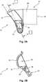
Die obere Schutzabdeckung
Der Absaugadapter
Die Handkreissäge
Der Befestigungsabschnitt
Der Sauganschlussabschnitt
Die Führungseinrichtung
Die Führungseinrichtung
Die Größe des Volumenelementes
Die Austrittsöffnung
Die Verstellbarkeit der Austrittsöffnung
Claims (7)
Translated fromGermanPriority Applications (6)
| Application Number | Priority Date | Filing Date | Title |
|---|---|---|---|
| DE201010041352DE102010041352A1 (en) | 2010-09-24 | 2010-09-24 | Hand-held power tool with a suction adapter |
| US13/199,903US20120073141A1 (en) | 2010-09-24 | 2011-09-13 | Hand-held electric power tool with a suction adapter |
| EP11181190.7AEP2433759B1 (en) | 2010-09-24 | 2011-09-14 | Handheld electric tool with a suction adapter |
| CN201110279124.4ACN102416618B (en) | 2010-09-24 | 2011-09-20 | There is the electric tools manually guided of suction adapter |
| JP2011208008AJP5780899B2 (en) | 2010-09-24 | 2011-09-22 | Hand-held power tool device with suction adapter |
| US14/461,075US20140352155A1 (en) | 2010-09-24 | 2014-08-15 | Hand-held electric power tool with a suction adapter |
Applications Claiming Priority (1)
| Application Number | Priority Date | Filing Date | Title |
|---|---|---|---|
| DE201010041352DE102010041352A1 (en) | 2010-09-24 | 2010-09-24 | Hand-held power tool with a suction adapter |
Publications (1)
| Publication Number | Publication Date |
|---|---|
| DE102010041352A1true DE102010041352A1 (en) | 2012-03-29 |
Family
ID=44582712
Family Applications (1)
| Application Number | Title | Priority Date | Filing Date |
|---|---|---|---|
| DE201010041352CeasedDE102010041352A1 (en) | 2010-09-24 | 2010-09-24 | Hand-held power tool with a suction adapter |
Country Status (5)
| Country | Link |
|---|---|
| US (2) | US20120073141A1 (en) |
| EP (1) | EP2433759B1 (en) |
| JP (1) | JP5780899B2 (en) |
| CN (1) | CN102416618B (en) |
| DE (1) | DE102010041352A1 (en) |
Families Citing this family (8)
| Publication number | Priority date | Publication date | Assignee | Title |
|---|---|---|---|---|
| DE102010041352A1 (en)* | 2010-09-24 | 2012-03-29 | Hilti Aktiengesellschaft | Hand-held power tool with a suction adapter |
| US8782906B2 (en)* | 2011-09-30 | 2014-07-22 | Robert Bosch Gmbh | Saw assembly with pivot hinge dust port |
| CN104203205B (en) | 2012-03-22 | 2017-06-23 | 富士胶片株式会社 | Transparency emulsification composition high and transparency cosmetic preparation high |
| JP5991929B2 (en)* | 2013-01-21 | 2016-09-14 | 株式会社マキタ | Dust collector and impact tool equipped with dust collector |
| US9521515B2 (en) | 2015-01-26 | 2016-12-13 | Mobli Technologies 2010 Ltd. | Content request by location |
| US20190111634A1 (en)* | 2017-10-13 | 2019-04-18 | Tti (Macao Commercial Offshore) Limited | Battery powered carpet seamer |
| US10875109B1 (en) | 2018-04-30 | 2020-12-29 | Kreg Enterprises, Inc. | Adaptive cutting system |
| CN109773269A (en)* | 2019-03-15 | 2019-05-21 | 上海华鄂工程技术有限公司 | A high-speed rotating cutting tool dust separation port with saw blade |
Citations (3)
| Publication number | Priority date | Publication date | Assignee | Title |
|---|---|---|---|---|
| DE7221303U (en)* | 1972-08-24 | Festo Maschinenfabrik Stoll G | Circular saw | |
| US6612038B2 (en)* | 2000-07-07 | 2003-09-02 | Hitachi Koki Co., Ltd. | Portable circular saw |
| DE10224837A1 (en)* | 2002-06-05 | 2004-01-08 | Robert Bosch Gmbh | machine tool |
Family Cites Families (49)
| Publication number | Priority date | Publication date | Assignee | Title |
|---|---|---|---|---|
| BE793459A (en)* | 1971-12-28 | 1973-04-16 | Hutchins Alma A | SANDING MACHINE |
| DE2603330C2 (en)* | 1976-01-29 | 1986-09-04 | Norbert 6109 Mühltal Loevenich | Device for removing cuttings, drilling dust and the like, especially with hand drills during the drilling process |
| JPS637218A (en)* | 1986-06-27 | 1988-01-13 | Hitachi Koki Co Ltd | Dust collecting mechanism for portable power tool |
| JPH0236097A (en)* | 1988-07-26 | 1990-02-06 | Koumu:Kk | Air cutter for concrete and the like |
| DE3921778A1 (en)* | 1989-07-01 | 1991-01-10 | Hilti Ag | HAND DEVICE WITH CUTTING OR GRINDING DISC |
| US5084972A (en)* | 1991-01-25 | 1992-02-04 | Waugh Ricky L | Device for collecting dust from a portable circular saw |
| US5074044A (en)* | 1991-04-26 | 1991-12-24 | Duncan C Warren | Dust disposal attachment for a rotary element of a power tool |
| US5235753A (en)* | 1992-03-20 | 1993-08-17 | Black & Decker Inc. | Circular saw lower guard chip deflector |
| US5327649A (en)* | 1993-02-11 | 1994-07-12 | Skinner Christopher L | Circular saw with dust collector |
| US5440809A (en)* | 1993-10-06 | 1995-08-15 | Padilla; Daniel G. | Dust collector for hand-held power tool |
| JP3611452B2 (en)* | 1998-06-19 | 2005-01-19 | リョービ株式会社 | Cutting powder discharge mechanism of circular saw machine |
| US6108912A (en)* | 1998-12-23 | 2000-08-29 | Radigan; Michael C. | Dust collecting shield for power tools |
| US6167626B1 (en)* | 1999-07-30 | 2001-01-02 | S-B Power Tool Company | Dust collection port for use with a saw |
| US6318352B1 (en)* | 2000-05-15 | 2001-11-20 | Michael Gnazzo | Dust and particle control attachment for a saw |
| DE10041906B4 (en)* | 2000-08-25 | 2011-06-09 | Hilti Aktiengesellschaft | Grinder with dust extraction |
| US6678960B2 (en)* | 2001-05-10 | 2004-01-20 | Dan Williams | Undercut saw with central height adjustment |
| US6557261B1 (en)* | 2001-08-21 | 2003-05-06 | John P. Buser | Dust-capturing adaptor for a saw |
| DE10153939A1 (en)* | 2001-11-06 | 2003-05-22 | Hilti Ag | Hand machine tool has fan wheel between suction pipe and separator and extending at least in part into duct collecting space |
| DE20203683U1 (en)* | 2002-03-08 | 2003-07-24 | Robert Bosch Gmbh, 70469 Stuttgart | Portable planer |
| US6748660B2 (en)* | 2002-05-15 | 2004-06-15 | John P. Buser | Debris-collection device for a power saw |
| US6648742B1 (en)* | 2002-06-04 | 2003-11-18 | Theodore R. Segiel Jr. | Dust director portable vacuum guard |
| US6857191B2 (en)* | 2002-11-07 | 2005-02-22 | Bettcher Industries, Inc. | Rotary knife having vacuum attachment |
| US6886258B2 (en)* | 2002-11-15 | 2005-05-03 | Richard C. Swanson | Hand-held rotary hedge trimmer |
| DE50306834D1 (en)* | 2002-11-22 | 2007-05-03 | Bosch Gmbh Robert | Electric hand tool |
| DE50309102D1 (en)* | 2002-11-22 | 2008-03-20 | Bosch Gmbh Robert | Electric circular saw machine |
| US6925917B2 (en)* | 2002-12-03 | 2005-08-09 | Robert J. Tilley | Tool provided with irrigation for transection of a band, ring or the like and method of use |
| US20040154168A1 (en)* | 2003-02-07 | 2004-08-12 | Mcdonald Jon Anthony | Dust and debris shield for powered hand tool |
| NL1022807C2 (en)* | 2003-02-28 | 2004-08-31 | Bosch Gmbh Robert | Planer with improved chip removal. |
| JP2005001896A (en)* | 2003-06-09 | 2005-01-06 | Fuji Heavy Ind Ltd | Glass cutting equipment |
| US7526866B2 (en)* | 2003-10-31 | 2009-05-05 | Black & Decker Inc. | Variable dust chute for circular saws |
| DE10357841B4 (en)* | 2003-12-11 | 2012-12-06 | Hilti Aktiengesellschaft | Jig saw with suction connection arrangement |
| US7000605B2 (en)* | 2004-01-20 | 2006-02-21 | Due Joseph E | Engraver apparatus and method |
| DE102004004003A1 (en)* | 2004-01-27 | 2005-08-11 | Robert Bosch Gmbh | Chip collecting container and system comprising a chip collecting container and a protective hood for a machine tool |
| CA2568529A1 (en)* | 2004-05-28 | 2005-12-15 | Scientific Molding Corporation Ltd. | Hand-held circular saw, in particular plunge-cut saw |
| US7559268B2 (en)* | 2004-07-16 | 2009-07-14 | Makita Corporation | Dust-collecting devices and cutting devices with the dust-collecting devices |
| JP4597598B2 (en)* | 2004-07-16 | 2010-12-15 | 株式会社マキタ | Slide circular saw with dust collector |
| US7328512B2 (en)* | 2004-09-14 | 2008-02-12 | Martin Charles B | Self-contained vacuum saw |
| DE102004063542A1 (en)* | 2004-12-30 | 2006-07-13 | Robert Bosch Gmbh | Hand tool with a guide channel |
| US20060169111A1 (en)* | 2005-02-02 | 2006-08-03 | Kozlowski Kevin M | Saw blade for drywall, saw apparatus utilizing saw blade and method |
| DE102005058296A1 (en)* | 2005-12-07 | 2007-06-21 | Robert Bosch Gmbh | Hand tool |
| US7661195B1 (en)* | 2006-10-06 | 2010-02-16 | Wood Billy R | Tool coupling and dust collection system |
| US8061044B2 (en)* | 2007-02-15 | 2011-11-22 | Hitachi Koki Co., Ltd. | Power tool with chips ejecting mechanism |
| DE102007056381A1 (en)* | 2007-11-22 | 2009-05-28 | Hilti Aktiengesellschaft | Hand tool |
| US20090183377A1 (en)* | 2008-01-21 | 2009-07-23 | Michael Loveless | Dust shroud for circular saws |
| US8523637B2 (en)* | 2009-07-21 | 2013-09-03 | Dustless Depot, Llc | Angle grinder dust shroud with slideable access hatch |
| US20110219628A1 (en)* | 2010-03-11 | 2011-09-15 | Ryan Harrison | Power tool with debris collection assembly |
| DE102010041352A1 (en)* | 2010-09-24 | 2012-03-29 | Hilti Aktiengesellschaft | Hand-held power tool with a suction adapter |
| DE102010063515A1 (en)* | 2010-12-20 | 2012-06-21 | Hilti Aktiengesellschaft | Suction module and hand tool with suction module |
| US8782906B2 (en)* | 2011-09-30 | 2014-07-22 | Robert Bosch Gmbh | Saw assembly with pivot hinge dust port |
- 2010
- 2010-09-24DEDE201010041352patent/DE102010041352A1/ennot_activeCeased
- 2011
- 2011-09-13USUS13/199,903patent/US20120073141A1/ennot_activeAbandoned
- 2011-09-14EPEP11181190.7Apatent/EP2433759B1/enactiveActive
- 2011-09-20CNCN201110279124.4Apatent/CN102416618B/enactiveActive
- 2011-09-22JPJP2011208008Apatent/JP5780899B2/enactiveActive
- 2014
- 2014-08-15USUS14/461,075patent/US20140352155A1/ennot_activeAbandoned
Patent Citations (3)
| Publication number | Priority date | Publication date | Assignee | Title |
|---|---|---|---|---|
| DE7221303U (en)* | 1972-08-24 | Festo Maschinenfabrik Stoll G | Circular saw | |
| US6612038B2 (en)* | 2000-07-07 | 2003-09-02 | Hitachi Koki Co., Ltd. | Portable circular saw |
| DE10224837A1 (en)* | 2002-06-05 | 2004-01-08 | Robert Bosch Gmbh | machine tool |
Also Published As
| Publication number | Publication date |
|---|---|
| CN102416618A (en) | 2012-04-18 |
| JP5780899B2 (en) | 2015-09-16 |
| EP2433759B1 (en) | 2017-04-19 |
| EP2433759A2 (en) | 2012-03-28 |
| US20120073141A1 (en) | 2012-03-29 |
| CN102416618B (en) | 2016-06-01 |
| US20140352155A1 (en) | 2014-12-04 |
| EP2433759A3 (en) | 2013-04-24 |
| JP2012066379A (en) | 2012-04-05 |
Similar Documents
| Publication | Publication Date | Title |
|---|---|---|
| EP2433759B1 (en) | Handheld electric tool with a suction adapter | |
| DE3038489C2 (en) | Hand machine tool with a rotating tool | |
| EP2465638B1 (en) | Suction module and hand tool machine with suction module | |
| DE10153939A1 (en) | Hand machine tool has fan wheel between suction pipe and separator and extending at least in part into duct collecting space | |
| EP1422032B1 (en) | Electric hand tool | |
| WO1988007906A1 (en) | Compass saw | |
| EP1074341A2 (en) | Dust protective cover for surface grinding tool | |
| DE10342507A1 (en) | Suction device for a drill comprises a fan arrangement which slides together with a suction head | |
| EP2052813A1 (en) | Plate grinder and grind plate for a plate grinder | |
| DE3740902A1 (en) | Rotating hollow cylindrical callus rasp with suction openings and a transparent dust-protection device belonging thereto and arranged thereover | |
| DE102011079504A1 (en) | Tool, in particular cutting tool, for a machine tool and machine tool with such a tool | |
| EP3338611A1 (en) | Suction device | |
| EP1136181A2 (en) | Single-handed grinding device | |
| EP3209464B1 (en) | Portable machine tool comprising an sds tool holder | |
| DE102012217734A1 (en) | FORWARD LIFTING LEVER FOR A MACHINE SAW | |
| EP2106327B1 (en) | Hand-held machine tool | |
| DE102004063542A1 (en) | Hand tool with a guide channel | |
| EP1422008B1 (en) | Electric hand -held circular saw | |
| DE602005005447T2 (en) | GEARED CIRCULAR SAW WITH FAN SYSTEM AND GUARD QUADRANT | |
| DE3884220T2 (en) | MOTORIZED DRIVING TOOL. | |
| DE102012001925A1 (en) | Surface grinder i.e. hand-held angle grinder, for performing concrete grinding works, has suction hood whose inner side is divided into inner and outer portions, where abrasive dust and sharpening object are sucked-off over outer portion | |
| EP1410875B1 (en) | Suction Device for a Motor Driven Hand Tool, especially a Router | |
| EP1697087B1 (en) | Electric hand-held machine tool | |
| EP0558893A2 (en) | Motor driven appliance being designed as handhold appliance for grinding, polishing, derosting or suchlike treatment of surfaces | |
| DE202016104254U1 (en) | Accessory and its combination with a power tool |
Legal Events
| Date | Code | Title | Description |
|---|---|---|---|
| R016 | Response to examination communication | ||
| R002 | Refusal decision in examination/registration proceedings | ||
| R003 | Refusal decision now final |