DE102010039545A1 - Method for detecting movements of finger of operator relative to capacitive sensor system of mobile telephone, involves establishing calibration process of sensor system if comparison result meets predetermined correspondence criterion - Google Patents
Method for detecting movements of finger of operator relative to capacitive sensor system of mobile telephone, involves establishing calibration process of sensor system if comparison result meets predetermined correspondence criterionDownload PDFInfo
- Publication number
- DE102010039545A1 DE102010039545A1DE102010039545ADE102010039545ADE102010039545A1DE 102010039545 A1DE102010039545 A1DE 102010039545A1DE 102010039545 ADE102010039545 ADE 102010039545ADE 102010039545 ADE102010039545 ADE 102010039545ADE 102010039545 A1DE102010039545 A1DE 102010039545A1
- Authority
- DE
- Germany
- Prior art keywords
- time
- sensor
- sensor electrode
- sensor system
- capacitive
- Prior art date
- Legal status (The legal status is an assumption and is not a legal conclusion. Google has not performed a legal analysis and makes no representation as to the accuracy of the status listed.)
- Granted
Links
Images


Classifications
- H—ELECTRICITY
- H03—ELECTRONIC CIRCUITRY
- H03K—PULSE TECHNIQUE
- H03K17/00—Electronic switching or gating, i.e. not by contact-making and –breaking
- H03K17/94—Electronic switching or gating, i.e. not by contact-making and –breaking characterised by the way in which the control signals are generated
- H03K17/945—Proximity switches
- H03K17/955—Proximity switches using a capacitive detector
- G—PHYSICS
- G06—COMPUTING OR CALCULATING; COUNTING
- G06F—ELECTRIC DIGITAL DATA PROCESSING
- G06F3/00—Input arrangements for transferring data to be processed into a form capable of being handled by the computer; Output arrangements for transferring data from processing unit to output unit, e.g. interface arrangements
- G06F3/01—Input arrangements or combined input and output arrangements for interaction between user and computer
- G06F3/03—Arrangements for converting the position or the displacement of a member into a coded form
- G06F3/041—Digitisers, e.g. for touch screens or touch pads, characterised by the transducing means
- G06F3/0416—Control or interface arrangements specially adapted for digitisers
- G06F3/0418—Control or interface arrangements specially adapted for digitisers for error correction or compensation, e.g. based on parallax, calibration or alignment
- G—PHYSICS
- G06—COMPUTING OR CALCULATING; COUNTING
- G06F—ELECTRIC DIGITAL DATA PROCESSING
- G06F3/00—Input arrangements for transferring data to be processed into a form capable of being handled by the computer; Output arrangements for transferring data from processing unit to output unit, e.g. interface arrangements
- G06F3/01—Input arrangements or combined input and output arrangements for interaction between user and computer
- G06F3/03—Arrangements for converting the position or the displacement of a member into a coded form
- G06F3/041—Digitisers, e.g. for touch screens or touch pads, characterised by the transducing means
- G06F3/044—Digitisers, e.g. for touch screens or touch pads, characterised by the transducing means by capacitive means
- H—ELECTRICITY
- H03—ELECTRONIC CIRCUITRY
- H03K—PULSE TECHNIQUE
- H03K2217/00—Indexing scheme related to electronic switching or gating, i.e. not by contact-making or -breaking covered by H03K17/00
- H03K2217/94—Indexing scheme related to electronic switching or gating, i.e. not by contact-making or -breaking covered by H03K17/00 characterised by the way in which the control signal is generated
- H03K2217/9401—Calibration techniques
- H03K2217/94021—Calibration techniques with human activation, e.g. processes requiring or being triggered by human intervention, user-input of digital word or analog voltage
- H—ELECTRICITY
- H03—ELECTRONIC CIRCUITRY
- H03K—PULSE TECHNIQUE
- H03K2217/00—Indexing scheme related to electronic switching or gating, i.e. not by contact-making or -breaking covered by H03K17/00
- H03K2217/94—Indexing scheme related to electronic switching or gating, i.e. not by contact-making or -breaking covered by H03K17/00 characterised by the way in which the control signal is generated
- H03K2217/96—Touch switches
- H03K2217/9607—Capacitive touch switches
- H03K2217/960735—Capacitive touch switches characterised by circuit details
- H03K2217/960745—Capacitive differential; e.g. comparison with reference capacitance
Landscapes
- Engineering & Computer Science (AREA)
- General Engineering & Computer Science (AREA)
- Theoretical Computer Science (AREA)
- Human Computer Interaction (AREA)
- Physics & Mathematics (AREA)
- General Physics & Mathematics (AREA)
- Measurement Of Length, Angles, Or The Like Using Electric Or Magnetic Means (AREA)
Abstract
Description
Translated fromGermanGebiet der ErfindungField of the invention
Die Erfindung betrifft ein Verfahren zum Erfassen von Bewegungen eines Objektes relativ zu einem kapazitiven Sensorsystem sowie ein kapazitives Sensorsystem hierfür. Des Weiteren betrifft die Erfindung ein elektrisches Gerät, insbesondere elektrisches Handgerät mit einem erfindungsgemäßen kapazitiven Sensorsystem, welches angepasst ist, das erfindungsgemäße Verfahren zum Erfassen von Bewegungen eines Objektes auszuführen.The invention relates to a method for detecting movements of an object relative to a capacitive sensor system and a capacitive sensor system therefor. Furthermore, the invention relates to an electrical device, in particular electrical hand-held device having a capacitive sensor system according to the invention, which is adapted to carry out the method according to the invention for detecting movements of an object.
Stand der TechnikState of the art
Im Stand der Technik sind kapazitive Sensoreinrichtungen bzw. kapazitive Sensorsysteme bekannt, welche beispielsweise an einem Handgerät angeordnet werden können. Die kapazitive Sensoreinrichtung kann hierbei vorgesehen sein, eine Annäherung an das Handgerät oder eine Bedienung des Handgerätes zu detektieren. Die kapazitive Sensoreinrichtung kann eine Anzahl von Sensorelektroden aufweisen. Die Sensoreinrichtung detektiert Veränderungen der dielektrischen Eigenschaften im Bereich der Sensorelektroden. Aus dem Ergebnis der Detektion kann auf einen Bedienvorgang geschlossen werden bzw. ein Bedienvorgang abgeleitet werden.In the prior art capacitive sensor devices or capacitive sensor systems are known, which can be arranged for example on a hand-held device. The capacitive sensor device may in this case be provided to detect an approach to the hand-held device or an operation of the hand-held device. The capacitive sensor device may comprise a number of sensor electrodes. The sensor device detects changes in the dielectric properties in the region of the sensor electrodes. From the result of the detection, it is possible to conclude an operating procedure or to derive an operating procedure.
Die von den Sensorelektroden bereitgestellten Sensordaten können einer zeitlichen Drift unterliegen, welche üblicherweise nicht bekannt ist. Um eine über die Zeit gleichbleibende Detektionsgüte zu gewährleisten, ist es notwendig, die kapazitive Sensoreinrichtung zu kalibrieren und die zeitliche Drift auszugleichen bzw. zu kompensieren. Hierzu ist es bekannt, die von den Sensorelektroden bereitgestellten Sensordaten zu überwachen. Ergibt die Überwachung, dass sich die Sensordaten über einen gewissen Zeitraum nur geringfügig ändern, wird angenommen, dass sich kein bewegliches Objekt in der Nähe der Sensorelektroden befindet. In diesem Fall wird ein Kalibriervorgang für das kapazitive Sensorsystem eingeleitet. Nachteilig hierbei ist allerdings, dass dieses Verfahren nur dann angewandt werden kann, wenn das Handgerät nicht bedient wird.The sensor data provided by the sensor electrodes may be subject to a time drift, which is usually not known. In order to ensure a constant quality of detection over time, it is necessary to calibrate the capacitive sensor device and compensate for the temporal drift or compensate. For this purpose, it is known to monitor the sensor data provided by the sensor electrodes. If the monitoring shows that the sensor data change only slightly over a certain period of time, it is assumed that there is no moving object in the vicinity of the sensor electrodes. In this case, a calibration process for the capacitive sensor system is initiated. The disadvantage here, however, is that this method can only be used if the handset is not operated.
Aufgabe der ErfindungObject of the invention
Der Erfindung liegt die Aufgabe zugrunde, Lösungen bereitzustellen, welche es ermöglichen, ein kapazitives Sensorsystem, insbesondere ein kapazitives Sensorsystem in einem Handgerät, zu kalibrieren, wobei der Kalibriervorgang auch dann zuverlässig eingeleitet werden kann, wenn das Handgerät durch eine Bedienperson bedient wird.The invention has for its object to provide solutions that make it possible to calibrate a capacitive sensor system, in particular a capacitive sensor system in a handset, the calibration process can be reliably initiated even when the handset is operated by an operator.
Erfindungsgemäße LösungInventive solution
Diese Aufgabe wird erfindungsgemäß durch ein Verfahren zum Erfassen von Bewegungen eins Objektes relativ zu einem kapazitiven Sensorsystem, durch ein kapazitives Sensorsystem zum Erfassen von Bewegungen sowie durch ein Handgerät mit einem erfindungsgemäßen kapazitiven Sensorsystem nach den unabhängigen Ansprüchen gelöst. Vorteilhafte Ausgestaltungen der Erfindung sind in den jeweiligen abhängigen Ansprüchen angegeben.This object is achieved by a method for detecting movements of an object relative to a capacitive sensor system, by a capacitive sensor system for detecting movements and by a hand-held device with a capacitive sensor system according to the invention according to the independent claims. Advantageous embodiments of the invention are specified in the respective dependent claims.
Bereitgestellt wird demnach ein Verfahren zum Erfassen von Bewegungen eines Objektes relativ zu einem kapazitiven Sensorsystem, welches zumindest eine erste Sensorelektrode umfasst, wobei das Verfahren zumindest umfasst:
- – Erfassen eines ersten zeitlichen Verlaufs von ersten Sensordaten, welche von der ersten Sensorelektrode bereit gestellt werden, wobei der erste zeitliche Verlauf die Bewegung des Objektes relativ zur ersten Sensorelektrode repräsentiert,
- – Vergleichen des ersten zeitlichen Verlaufs mit einem zeitlichen Verlauf erster Referenzdaten,
- – Detektieren, ob der Vergleich des ersten zeitlichen Verlaufes mit den ersten Referenzdaten zumindest ein vorbestimmtes Übereinstimmungskriterium erfüllt, und
- – Einleiten eines Kalibriervorganges des kapazitiven Sensorsystems, sofern der Vergleich das zumindest eine vorbestimmte Übereinstimmungskriterium erfüllt.
- Detecting a first time profile of first sensor data provided by the first sensor electrode, wherein the first time profile represents the movement of the object relative to the first sensor electrode,
- Comparing the first time course with a temporal course of the first reference data,
- Detecting whether the comparison of the first time course with the first reference data fulfills at least one predetermined matching criterion, and
- - Initiate a calibration of the capacitive sensor system, if the comparison meets the at least one predetermined match criterion.
Das kapazitive Sensorsystem kann zumindest eine zweite Sensorelektrode umfassen und das Verfahren kann zusätzlich umfassen:
- – Erfassen eines zweiten zeitlichen Verlaufs von zweiten Sensordaten, welche von der zweiten Sensorelektrode bereit gestellt werden, wobei der zweite zeitliche Verlauf die Bewegung des Objektes relativ zur zweiten Sensorelektrode repräsentiert,
- – Vergleichen des zweiten zeitlichen Verlaufs mit einem zeitlichen Verlauf zweiter Referenzdaten, und
- – Detektieren, ob der Vergleich des zweiten zeitlichen Verlaufes mit den zweiten Referenzdaten zumindest ein vorbestimmtes Übereinstimmungskriterium erfüllt.
- Detecting a second time profile of second sensor data provided by the second sensor electrode, wherein the second time profile represents the movement of the object relative to the second sensor electrode,
- - Comparing the second time course with a time course of second reference data, and
- - Detecting whether the comparison of the second time course with the second reference data meets at least one predetermined match criterion.
Der zeitliche Verlauf der ersten Referenzdaten kann ein Annähern des Objektes an die erste Sensorelektrode mit anschließendem Entfernen des Objektes von der ersten Sensorelektrode repräsentieren. Der zeitliche Verlauf der zweiten Referenzdaten kann ein Annähern des Objektes an die zweite Sensorelektrode mit anschließendem Entfernen des Objektes von der zweiten Sensorelektrode repräsentieren. Das Annähern des Objektes an die erste Sensorelektrode kann zeitlich vor dem Annähern des Objektes an die zweite Sensorelektrode und das Entfernen des Objektes von der ersten Sensorelektrode kann zeitlich vor dem Entfernen des Objektes von der zweiten Sensorelektrode erfolgen.The temporal course of the first reference data may represent an approach of the object to the first sensor electrode with subsequent removal of the object from the first sensor electrode. The temporal course of the second reference data may represent an approach of the object to the second sensor electrode with subsequent removal of the object from the second sensor electrode. The approach of the object to the first sensor electrode can be timed before approaching the Object to the second sensor electrode and the removal of the object from the first sensor electrode can take place before the removal of the object from the second sensor electrode.
Das Annähern des Objektes an die zweite Sensorelektrode kann zeitlich nach dem Entfernen des Objektes von der ersten Sensorelektrode erfolgen.The approach of the object to the second sensor electrode can take place temporally after the removal of the object from the first sensor electrode.
Vorteilhaft ist es, wenn der erste zeitliche Verlauf und der zweite zeitliche Verlauf jeweils durch eine Sequenz von differentiellen Sensordaten gebildet werden, wobei ein differentielles Sensordatum aus der Differenz zweier zeitlich aufeinanderfolgender Sensorsdaten gebildet wird.It is advantageous if the first time profile and the second time profile are each formed by a sequence of differential sensor data, wherein a differential sensor data is formed from the difference between two time-sequential sensor data.
Der erste zeitliche Verlauf und der zweite zeitliche Verlauf können jeweils aus der Summe zumindest zweier zeitlich aufeinanderfolgender differentieller Sensordaten bzw. Sensordatenwerte ermittelt werden.The first time profile and the second time profile can each be determined from the sum of at least two time-sequential differential sensor data or sensor data values.
Es kann ein Referenzwert vorgesehen sein, wobei Einzelwerte der zeitlichen Verläufe, welche größer als der Referenzwert sind, jeweils ein Annähern des Objektes an die jeweilige Sensorelektrode beschreiben und Einzelwerte der zeitlichen Verläufe, welche kleiner als der Referenzwert sind, jeweils ein Entfernen des Objektes von der jeweiligen Sensorelektrode beschreiben.A reference value can be provided, wherein individual values of the temporal courses, which are greater than the reference value, respectively describe an approaching of the object to the respective sensor electrode and individual values of the time courses, which are smaller than the reference value, respectively a removal of the object from the describe each sensor electrode.
Das zumindest eine Übereinstimmungskriterium kann umfassen:
- – der erste zeitliche Verlauf überschreitet zu einem ersten Zeitpunkt einen ersten Schwellenwert,
- – der erste zeitliche Verlauf unterschreitet zu einem zweiten Zeitpunkt einen zweiten Schwellenwert, wobei der zweite Zeitpunkt zeitlich nach dem ersten Zeitpunkt liegt,
- – der zweite zeitliche Verlauf überschreitet zu einem dritten Zeitpunkt einen dritten Schwellenwert,
- – der zweite zeitliche Verlauf unterschreitet zu einem vierten Zeitpunkt einen vierten Schwellenwert, wobei der vierte Zeitpunkt zeitlich nach dem dritten Zeitpunkt liegt.
- The first time course exceeds a first threshold at a first time,
- The first time profile falls short of a second threshold at a second time, the second time being later than the first time,
- The second time course exceeds a third threshold at a third time,
- The second time profile falls below a fourth threshold at a fourth time, the fourth time being later than the third time.
Es kann vorgesehen sein, dass sämtliche der Einzelkriterien oder nur einzelne Einzelkriterien erfüllt sein müssen, damit das Übereinstimmungskriterium erfüllt ist.It can be provided that all of the individual criteria or only individual individual criteria must be met in order for the matching criterion to be met.
Der dritte Zeitpunkt kann zeitlich nach dem zweiten Zeitpunkt liegen.The third time may be later than the second time.
Es hat sich als vorteilhaft herausgestellt, wenn das Überschreiten des ersten Schwellenwertes und das Unterschreiten des zweiten Schwellenwertes innerhalb eines vorbestimmten ersten Zeitraumes erfolgt, und/oder das Überschreiten des dritten Schwellenwertes und das Unterschreiten des vierten Schwellenwertes innerhalb eines vorbestimmten zweiten Zeitraumes erfolgt. Damit kann die Stabilität und Zuverlässigkeit der Detektion erhöht werden.It has proven to be advantageous if the first threshold value is exceeded and the second threshold value is undershot within a predetermined first time period, and / or if the third threshold value is exceeded and the fourth threshold value is undershot within a predetermined second time period. Thus, the stability and reliability of the detection can be increased.
Des Weiteren wird durch die Erfindung ein kapazitives Sensorsystem bereitgestellt, welches zumindest eine Sensorelektrode umfasst, wobei die zumindest eine Sensorelektrode mit einer Auswerteeinrichtung des kapazitiven Sensorsystems gekoppelt ist, und wobei die Auswerteeinrichtung angepasst ist, ein erfindungsgemäßes Verfahren zum Erfassen von Bewegungen eines Objektes relativ zu der zumindest einen Sensorelektrode des kapazitiven Sensorsystems auszuführen.Furthermore, the invention provides a capacitive sensor system which comprises at least one sensor electrode, wherein the at least one sensor electrode is coupled to an evaluation device of the capacitive sensor system, and wherein the evaluation device is adapted, a method according to the invention for detecting movements of an object relative to the execute at least one sensor electrode of the capacitive sensor system.
Ferner wird durch die Erfindung ein elektrisches Gerät bereitgestellt, insbesondere elektrisches Handgerät, mit einem kapazitiven Sensorsystem, wobei das kapazitive Sensorsystem zumindest eine Sensorelektrode umfasst, wobei die zumindest eine Sensorelektrode mit einer Auswerteeinrichtung des kapazitiven Sensorsystems gekoppelt ist, und wobei die Auswerteeinrichtung angepasst ist, ein erfindungsgemäßes Verfahren zum Erfassen von Bewegungen eines Objektes relativ zu der zumindest einen Sensorelektrode des kapazitiven Sensorsystems auszuführen.Furthermore, the invention provides an electrical device, in particular an electrical hand-held device, with a capacitive sensor system, wherein the capacitive sensor system comprises at least one sensor electrode, wherein the at least one sensor electrode is coupled to an evaluation device of the capacitive sensor system, and wherein the evaluation device is adapted Inventive method for detecting movements of an object relative to the at least one sensor electrode of the capacitive sensor system.
Die zumindest eine Sensorelektrode kann an einer Oberfläche oder nahe unterhalb einer Oberfläche des Handgerätes angeordnet sein.The at least one sensor electrode may be disposed on or near a surface of the handset.
Das Handgerät kann beispielsweise ein Mobiltelefon, eine kabellose Computermaus, eine Fernbedienung, ein Eingabemittel für eine Spielkonsole, ein mobiler Kleincomputer, oder dergleichen sein.The handset may be, for example, a mobile phone, a wireless computer mouse, a remote control, an input device for a game console, a mobile minicomputer, or the like.
Kurzbeschreibung der FigurenBrief description of the figures
Weitere Einzelheiten und Merkmale der Erfindung sowie konkrete Ausführungsbeispiele der Erfindung ergeben sich aus der nachfolgenden Beschreibung in Verbindung mit der Zeichnung. Es zeigt:Further details and features of the invention and specific embodiments of the invention will become apparent from the following description taken in conjunction with the drawings. It shows:
Detaillierte Beschreibung der ErfindungDetailed description of the invention
Das kapazitive Sensorsystem umfasst eine erste Sensorelektrode E1 und eine zweite Sensorelektrode E2. Die Sensorelektroden E1 und E2 sind jeweils an der Oberfläche eines hier nicht gezeigten elektrischen Handgerätes, etwa ein Mobiltelefon oder eine Fernbedienung angeordnet. Die Sensorelektroden E1, E2 sind derart an der Oberfläche bzw. nahe unterhalb der Oberfläche des elektrischen Handgerätes angeordnet, dass, wenn das Handgerät in einer Hand gehalten wird, beide Elektroden E1, E2 mit einem Finger, etwa dem Daumen erreichbar sind.The capacitive sensor system comprises a first sensor electrode E1 and a second sensor electrode E2. The sensor electrodes E1 and E2 are respectively arranged on the surface of an electric hand-held device, not shown here, such as a mobile phone or a remote control. The sensor electrodes E1, E2 are arranged on the surface or near the surface of the electrical handset such that, when the handset is held in one hand, both electrodes E1, E2 can be reached with a finger, such as the thumb.
Um die Kalibrierung des kapazitiven Sensorsystems einzuleiten, wird der Finger F zunächst nahe über die erste Sensorelektrode E1 bewegt. Dabei nähert sich der Finger F der ersten Sensorelektrode E1 an. Wird die Bewegung fortgeführt, nähert sich der Finger F auch der zweiten Sensorelektrode E2 an, wobei sich der Finger F gleichzeitig wieder von der ersten Sensorelektrode E1 entfernt. Wird die Bewegung noch weiter fortgeführt, entfernt sich der Finger F schließlich auch wieder von der zweiten Sensorelektrode E2.To initiate the calibration of the capacitive sensor system, the finger F is first moved close to the first sensor electrode E1. In this case, the finger F approaches the first sensor electrode E1. If the movement continues, the finger F also approaches the second sensor electrode E2, with the finger F at the same time moving away from the first sensor electrode E1. If the movement continues even further, the finger F eventually moves away from the second sensor electrode E2.
Der in
Zudem handelt es sich bei dem hier gezeigten Bewegungsablauf um einen besonders intuitiven Bewegungsablauf, welcher von einem Benutzer eines elektrischen Handgerätes einfach erlernt werden kann, wie mit Bezug auf die
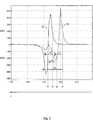
Der zeitliche Verlauf der von den jeweiligen Sensorelektroden E1 und E2 bereitgestellten Sensordaten wird erfindungsgemäß erfasst und mit vorbestimmten Referenzdaten verglichen, um zu detektieren, ob es sich bei der erfassten Fingerbewegung um eine Bewegung handelt, welche für das Einleitung eines Kalibriervorganges bestimmt ist.The time profile of the sensor data provided by the respective sensor electrodes E1 and E2 is inventively detected and compared with predetermined reference data to detect whether the detected finger movement is a movement that is intended for the initiation of a calibration process.
Ein Beispiel für den zeitlichen Verlauf der von den Sensorelektroden E1 und E2 bereitgestellten Sensordaten ist mit Bezug auf
Anstelle von zwei Sensorelektroden E1, E2 kann auch lediglich eine Sensorelektrode vorgesehen sein. Hierbei wird das von der Sensorelektrode bereitgestellte Sensorsignal mit einem Referenzsignal bzw. mit Referenzdaten verglichen. Ergibt der Vergleich, dass das Sensorsignal einer vorbestimmten Bewegung entspricht, wird der Kalibriervorgang eingeleitet. Damit wird es möglich, besonders einfach ausgeführte kapazitive Sensorsysteme bereitzustellen, welche dennoch zuverlässig kalibriert werden können, auch wenn sich das Handgerät, in welchem das Sensorsystem angeordnet ist, in Bedienung befindet.Instead of two sensor electrodes E1, E2, only one sensor electrode can be provided. Here, the sensor signal provided by the sensor electrode is compared with a reference signal or with reference data. If the comparison reveals that the sensor signal corresponds to a predetermined movement, the calibration process is initiated. This makes it possible to provide particularly simple capacitive sensor systems which can nevertheless be calibrated reliably, even if the hand-held device in which the sensor system is arranged is in operation.
Es ist auch möglich, ein kapazitives Sensorsystem bereitzustellen, welches eine Vielzahl von Sensorelektroden aufweist. Die Sensorelektroden können etwa in einer Matrix angeordnet sein und etwa Bestandteil eines kapazitiven Displays sein. Dabei können einige, z. B. eine Elektrode oder zwei oder mehrere Elektroden der Elektrodenmatrix, als Sensorelektroden zum Erfassen der für das Einleiten eines Kalibriervorganges vorgesehenen Bewegung vorgesehen sein.It is also possible to provide a capacitive sensor system having a plurality of sensor electrodes. The sensor electrodes may be arranged approximately in a matrix and be approximately part of a capacitive display. Here are some, z. As an electrode or two or more electrodes of the electrode matrix, as Sensor electrodes for detecting the intended for the initiation of a calibration movement can be provided.
In
Indem jeweils der zeitliche Verlauf der differenziellen Sensordaten verwendet wird, kann besonders einfach zwischen einem Annähern an eine Sensorelektrode und einem Entfernen von einer Sensorelektrode unterschieden werden. Ein positiver Wert eines differenziellen Sensordatums entspricht einer Annäherung an die Elektrode, während ein negativer Wert eines differenziellen Sensordatums einem Entfernen von der Elektrode entspricht.By using in each case the time profile of the differential sensor data, it is particularly easy to distinguish between an approach to a sensor electrode and a removal from a sensor electrode. A positive value of a differential sensor datum corresponds to an approach to the electrode while a negative value of a differential sensor datum corresponds to a removal from the electrode.
Alternativ kann auch die Summe zumindest zweier zeitlich aufeinanderfolgender differentieller Sensordatenwerte gebildet werden, wobei die differentiellen Sensordatenwerte wie vorstehend beschrieben gebildet werden können, also
- et
- Wert des zeitlichen Verlaufes zum Zeitpunkt t
- wt, wt-n
- Sensordatenwert zum Zeitpunkt t bzw. t-n
- m
- Anzahl der zeitlich aufeinanderfolgenden differentiellen Sensordatenwerte
- et
- Value of the time course at time t
- wt , wtn
- Sensor data value at time t or tn
- m
- Number of time-sequential differential sensor data values
Der in
Nachdem sich der Finger von der ersten Sensorelektrode E1 entfernt hat, nähert sich dieser der zweiten Sensorelektrode E2 an, was zu positiven differenziellen Sensordatenwerten im zweiten Verlauf S2 führt. Auch hier entfernt sich der Finger wieder von der zweiten Sensorelektrode E2, so dass auch die differenziellen Sensordatenwerte der zweiten Sensorelektrode E2 einen negativen Wert annehmen. Erfindungsgemäß können die in
Die zeitlichen Verläufe S1, S2 der tatsächlich an den Sensorelektroden erfassten differenziellen Sensordaten können jeweils mit einem zeitlichen Verlauf von Referenzdaten verglichen werden. Dabei kann ermittelt werden, ob die zeitlichen Verläufe S1, S2 mit den zeitlichen Verläufen der Referenzdaten übereinstimmen bzw. um lediglich vorbestimmte Toleranzen voneinander abweichen. Für das Ermitteln bzw. Detektieren der Übereinstimmung können ein oder mehrere Übereinstimmungskriterien festgelegt werden. Sind ein oder mehrere Übereinstimmungskriterien erfüllt, gilt die für das Einleiten eines Kalibriervorganges vorgesehene Bewegung als erkannt und der Kalibriervorgang des kapazitiven Sensorsystems kann eingeleitet werden. Wird die für das Einleiten des Kalibriervorganges bestimmte Bewegung nicht erkannt, verbleibt die kapazitive Sensoreinrichtung in einem normalen Betriebsmodus, in welchem das kapazitive Sensorsystem zum Erfassen von Bedienabläufen vorgesehen ist.The time profiles S1, S2 of the differential sensor data actually acquired at the sensor electrodes can each be compared with a time profile of reference data. In this case, it can be determined whether the time profiles S1, S2 coincide with the time profiles of the reference data or deviate from one another by merely predetermined tolerances. One or more match criteria may be specified for determining or detecting the match. If one or more matching criteria are met, the movement provided for initiating a calibration process is considered to be recognized and the calibration process of the capacitive sensor system can be initiated. If the movement determined for initiating the calibration process is not recognized, the capacitive sensor device remains in a normal operating mode, in which the capacitive sensor system is provided for detecting operating sequences.
Zum Vergleichen der zeitlichen Verläufe S1, S2 mit den zeitlichen Verläufen von Referenzdaten können beispielsweise Verfahren zur Musterkennung, etwa Hidden-Markov-Modelle verwendet werden. Als Übereinstimmungskriterium kann hier der Grad der Ähnlichkeit der zeitlichen Verläufe S1, S2 zu den zeitlichen Verlaufen der Referenzdaten vorgesehen sein.To compare the time profiles S1, S2 with the time profiles of reference data, methods for pattern recognition, for example hidden Markov models, can be used, for example. As a matching criterion, the degree of similarity of the time profiles S1, S2 to the time course of the reference data can be provided here.
In einer weiteren Ausgestaltung können die zeitlichen Verläufe S1, S2 mit den zeitlichen Verläufen von Referenzdaten verglichen werden, wobei die Referenzdaten die zeitliche Abfolge von Überschreiten bzw. Unterschreiten vorbestimmter Schwellenwerte von den erfassten differenziellen Sensordaten definieren. In a further refinement, the time profiles S1, S2 can be compared with the time profiles of reference data, the reference data defining the chronological sequence of exceeding or falling below predetermined threshold values from the detected differential sensor data.
Beispielsweise können ein erster Schwellenwert SW1 und ein zweiter Schwellenwert SW2 festgelegt sein. Für das Überschreiten und Unterschreiten der Schwellenwerte SW1 bzw. SW2 kann beispielsweise folgende zeitliche Abfolge definiert werden:
- – der erste Verlauf S1 überschreitet zu einem ersten Zeitpunkt t1 den ersten Schwellenwert SW1,
- – der erste Verlauf SW1 unterschreitet zu einem zweiten Zeitpunkt t2 einen zweiten Schwellenwert SW2, wobei der zweite Zeitpunkt t2 zeitlich nach dem ersten Zeitpunkt t1 liegt,
- – der zweite Verlauf S2 überschreitet zu einem dritten Zeitpunkt t3 den Schwellenwert SW1,
- – der zweite Verlauf S2 unterschreitet zu einem vierten Zeitpunkt t4 den zweiten Schwellenwert SW2, wobei der vierte Zeitpunkt t4 zeitlich nach dem dritten Zeitpunkt t3 liegt.
- The first course S1 exceeds the first threshold value SW1 at a first time t1,
- The first course SW1 falls short of a second threshold value SW2 at a second time t2, the second time point t2 being later than the first time t1,
- The second course S2 exceeds the threshold value SW1 at a third time t3,
- - The second course S2 falls short of the second threshold SW2 at a fourth time t4, wherein the fourth time t4 is later than the third time t3.
Um die Detektionsgenauigkeit weiter zu erhöhen bzw. die Wahrscheinlichkeit einer Fehlauslösung zu verringern, können Zeiträume vorgesehen sein, innerhalb welcher die Schwellenwerte überschritten bzw. unterschritten werden müssen. Beispielsweise kann vorgesehen sein, dass der erste Verlauf S2 den zweiten Schwellenwert SW2 innerhalb eines Zeitraumes Z1 unterschreiten muss, nachdem dieser den ersten Schwellenwert SW1 überschritten hat. In ähnlicher Weise kann für den zweiten Verlauf S2 ein Zeitraum Z2 definiert werden, innerhalb welchem nach dem Überschreiten des ersten Schwellenwertes SW1 der zweite Schwellenwert SW2 unterschritten werden muss.In order to further increase the detection accuracy or to reduce the probability of false triggering, periods may be provided within which the threshold values must be exceeded or undershot. For example, it may be provided that the first curve S2 must fall below the second threshold value SW2 within a time period Z1 after it has exceeded the first threshold value SW1. Similarly, for the second course S2, a period Z2 can be defined, within which the second threshold value SW2 must be exceeded after exceeding the first threshold value SW1.
Alternativ oder zusätzlich kann ein dritter Zeitraum Z3 definiert werden, innerhalb welchem der zweite Verlauf S2 den ersten Schwellenwert SW1 überschreiten muss, nachdem der erste Verlauf S1 den zweiten Schwellen SW2 unterschritten hat. Alternativ oder zusätzlich kann auch ein vierter Zeitraum Z4 vorgesehen sein, innerhalb welchem die zeitlichen Verläufe S1 und S2 die Schwellenwerte SW1 und SW2 wie vorstehend beschrieben überschreiten bzw. unterschreiten müssen.Alternatively or additionally, a third time period Z3 can be defined within which the second course S2 must exceed the first threshold value SW1 after the first course S1 has fallen below the second threshold SW2. Alternatively or additionally, a fourth time period Z4 can also be provided, within which the time profiles S1 and S2 must exceed or fall below the threshold values SW1 and SW2 as described above.
Die Schwellenwerte SW1 und SW2 können für beide zeitlichen Verläufe S1 und S2 jeweils verschieden festgelegt werden. Ebenso kann beispielsweise festgelegt werden, dass für das Erkennen einer Bewegung zum Einleiten eines Kalibriervorganges lediglich jeweils der Schwellenwert SW1 überschritten werden muss, wobei das Unterschreiten des zweiten Schwellenwertes SW2 jeweils unberücksichtigt bleiben kann. Umgekehrt kann auch vorgesehen sein, dass nur das Unterschreiten des zweiten Schwellenwertes SW2 ausgewertet wird.The threshold values SW1 and SW2 can be set differently for both time courses S1 and S2. Likewise, for example, it can be established that only the respective threshold value SW1 must be exceeded for detecting a movement for initiating a calibration process, whereby falling below the second threshold value SW2 can be disregarded in each case. Conversely, it can also be provided that only falling below the second threshold value SW2 is evaluated.
Zum Überwachen, ob die zeitlichen Verläufe S1, S2 die jeweiligen Schwellenwerte SW1 bzw. SW2 innerhalb der vorgegeben Zeiträume überschreiten bzw. unterschreiten, kann jeweils ein Timer gestartet werden, welcher terminiert, sobald das zu überwachende Ereignis bzw. Ereignisse eintreten.For monitoring whether the time profiles S1, S2 exceed or fall short of the respective threshold values SW1 and SW2 within the predetermined periods, a timer can be started in each case, which terminates as soon as the event or events to be monitored occur.
Das Mobiltelefon kann eine berührungssensitve Eingabefläche aufweisen. Unterhalb der Oberfläche der Eingabefläche können die Sensorelektroden des erfindungsgemäßen kapazitiven Sensorsystems angeordnet sein. Sofern es sich bei der berührungssensitiven Eingabefläche um eine Eingabefläche auf kapazitiver Basis handelt, können auch Elektroden der berührungssensitiven kapazitiven Eingabefläche verwendet werden, um die für das einleiten des Kalibriervorganges vorgesehene Bewegung zu erfassen bzw. zu detektieren.The mobile phone may have a touch-sensitive input surface. Below the surface of the input surface, the sensor electrodes of the capacitive sensor system according to the invention can be arranged. If the touch-sensitive input surface is an input surface on a capacitive basis, it is also possible to use electrodes of the contact-sensitive capacitive input surface in order to detect or detect the movement provided for initiating the calibration process.
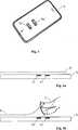
Anhand der
Die Bewegung des Fingers relativ zu den Sensorelektroden E1, E2 kann mit der Bewegung eines ”virtuellen Gegenstandes”, welcher über dem Display des elektrischen Handgerätes G angeordnet ist, in Verbindung gebracht werden. Dieser virtuelle Gegenstand kann ein Tuch T (virtuelles Tuch) sein, welches sich vorzugsweise im Bereich der Sensorelektroden E1 und E2 über das Display legt. Das virtuelle Tuch T kann vorgesehen sein, die Bedienung des Handgerätes G zu verhindern, solange das virtuelle Tuch T über das Display gelegt ist.The movement of the finger relative to the sensor electrodes E1, E2 may be associated with the movement of a "virtual item" disposed over the display of the electrical handset G. This virtual object may be a cloth T (virtual cloth), which preferably overlies the display in the region of the sensor electrodes E1 and E2. The virtual cloth T may be provided to prevent the operation of the handset G as long as the virtual cloth T is placed over the display.
Die mit Bezug auf
Indem der Benutzer des Handgerätes G das virtuelle Tuch T anhebt wird einerseits die Bedienung des Handgerätes freigegeben und andererseits kann gezielt der Kalibriervorgang des Sensorsystems eingeleitet werden. Damit kann in vorteilhafter Weise der Kalibriervorgang eingeleitet werden, sobald der Benutzer beabsichtigt, das Handgerät zu bedienen.By the user of the handset G lifts the virtual cloth T on the one hand, the operation of the handset is released and on the other hand, the calibration of the sensor system can be specifically initiated. Thus, the calibration process can be initiated advantageously as soon as the user intends to operate the handset.
Sofern während der Bedienung des Handgerätes ein weiterer Kalibriervorgang erforderlich sein sollte, kann das virtuelle Tuch T wieder über die Eingabefläche gelegt werden, sodass für eine weitere Bedienung des Handgerätes G das virtuelle Tuch T zunächst wieder (assoziativ) angehoben werden muss, was wiederum ein Kalibiervorgang einleitet.If during the operation of the handset, a further calibration should be required, the virtual cloth T can be placed over the input surface again, so for a further operation of the handset G, the virtual cloth T must first be raised again (associative), which in turn a calibration process initiates.
Sofern das Handgerät G ein Display aufweist, kann das virtuelle Tuch T in Form eines stilisierten Tuches auf dem Display angezeigt werden, um von dem Bediener ein Anheben des Tuches T anzufordern.If the handset G has a display, the virtual cloth T can be displayed in the form of a stylized cloth on the display to request a lift of the cloth T from the operator.
Wird die Bedienfläche des Handgerätes auf dem Display angezeigt, etwa bei einem berührungssensitiven Display, kann das virtuelle Tuch T die Bedienfläche zumindest teilweise ”überdecken”. Das virtuelle Tuch T kann dabei zumindest teilweise transparent ausgestaltet sein, sodass die Bedienelemente der Bedienfläche weiterhin sichtbar sind. Um die Bedienfläche freizugeben, kann der Benutzer das virtuelle Tuch T mit dem Finger (assoziativ) anheben, wie vorstehend beschrieben.If the operating surface of the handheld device is shown on the display, for example in the case of a touch-sensitive display, the virtual cloth T can at least partially "cover" the operating surface. The virtual cloth T can be made at least partially transparent, so that the controls of the control surface are still visible. To release the control surface, the user may lift the virtual cloth T with his finger (associatively), as described above.
Das virtuelle Tuch T kann auch auf einer entfernten Anzeigeeinrichtung, etwa ein Fernsehgerät oder Monitor, angezeigt werden, wobei das Handgerät als Bedieneinrichtung, etwa eine Fernbedienung, für die Anzeigeeinrichtung ausgestaltet sein kann. Auf der Anzeigeeinrichtung können Bedienelemente angezeigt werden, welche mit Hilfe der Bedieneinrichtung betätigt und/oder ausgewählt werden können. Bedienelemente können Auswahlknöpfe, Auswahllisten oder dergleichen sein. Um von dem Benutzer der Bedieneinrichtung das Einleiten eines Kalibriervorganges des in der Bedieneinrichtung angeordneten kapazitiven Sensorsystems anzufordern, kann auf der entfernten Anzeigeeinrichtung das virtuelle Tuch T eingeblendet werden. Um die Bedienung der Bedieneinrichtung freizugeben, muss der Benutzer das virtuelle Tuch mit einem Finger anheben, wie vorstehend beschrieben, wobei das Bewegen des Fingers relativ zu den an der Bedieneinrichtung angeordneten Sensorelektroden erfolgt.The virtual cloth T can also be displayed on a remote display device, such as a television or monitor, wherein the handset can be configured as a control device, such as a remote control, for the display device. On the display controls can be displayed, which can be operated and / or selected by means of the operating device. Controls may be radio buttons, selection lists or the like. In order to request the user of the operating device to initiate a calibration process of the capacitive sensor system arranged in the operating device, the virtual cloth T can be superimposed on the remote display device. In order to release the operation of the operating device, the user must lift the virtual cloth with a finger, as described above, wherein the movement of the finger is relative to the sensor electrodes arranged on the operating device.
Dem Bediener kann auch auf andere Art und Weise signalisiert werden, dass das virtuelle Tuch T angehoben werden muss, etwa über eine an dem Handgerät angeordnete LED. Dies ist dann vorteilhaft, wenn das Handgerät nicht über ein Display verfügt, auf dem das virtuelle Tuch angezeigt werden kann.The operator can also be signaled in another way that the virtual cloth T must be raised, for example via an LED arranged on the handheld device. This is advantageous if the handset does not have a display on which the virtual cloth can be displayed.
Das erfindungsgemäße Verfahren ist auch geeignet, einen Kalibriervorgang eines an einer Tastatur angeordneten kapazitiven Sensorsystems einzuleiten. Zusätzlich zu den Tasten der Tastatur, welche als kapazitive Taster ausgestaltet sein können, sind an der Tastatur die Sensorelektroden eines kapazitiven. Sensorsystems angeordnet. Die Tastatur kann eine Computertastatur sein. Mit dem kapazitiven Sensorsystem kann die Eingabemöglichkeit der Tastatur erweitert werden, etwa als Ersatz für eine Maus bzw. Computermaus. Mit einer entsprechenden Bewegung eines Finger oder der ganzen Hand relativ zu den Sensorelektroden des kapazitiven Sensorsystems kann der Kalibriervorgang des kapazitiven Sensorsystems eingeleitet werden. Das anzuhebende virtuelle Tuch T kann beispielsweise auf einem Display angezeigt werden. Die Tastatur kann eine drahtgebundene oder eine drahtlose Tastatur sein. Bei einer Tastatur mit kapazitiven Tastern können auch die kapazitiven Taster zum Erfassen der den Kalibriervorgang einleitenden Bewegung vorgesehen sein.The method according to the invention is also suitable for initiating a calibration process of a capacitive sensor system arranged on a keyboard. In addition to the keys of the keyboard, which may be configured as capacitive buttons, the sensor electrodes of a capacitive are on the keyboard. Sensor system arranged. The keyboard can be a computer keyboard. With the capacitive sensor system, the input possibility of the keyboard can be extended, for example as a replacement for a mouse or computer mouse. With a corresponding movement of a finger or the whole hand relative to the sensor electrodes of the capacitive sensor system, the calibration process of the capacitive sensor system can be initiated. The virtual cloth T to be lifted can be displayed, for example, on a display. The keyboard may be a wired or a wireless keyboard. In the case of a keyboard with capacitive pushbuttons, the capacitive pushbuttons can also be provided for detecting the movement that initiates the calibration process.
Sofern das kapazitive Sensorsystem nicht kalibriert werden muss, was von dem kapazitiven Sensorsystems selbst erkannt werden kann, kann die einen Kalibriervorgang einleitende Bewegung als normale Bediengeste detektiert werden.If the capacitive sensor system does not have to be calibrated, which can be detected by the capacitive sensor system itself, the movement initiating a calibration process can be detected as a normal operating gesture.
Ähnlich zum virtuellen Tuch T kann die Bedienfläche auch von einer virtuellen Platte abgedeckt sein, die von dem sich anhebenden Finger (assoziativ) zertrümmert wird. Ebenso kann sich über der Bedienfläche ein virtuelles Nebelfeld legen, welches sich aufgrund des durch die Fingerbewegung entstehenden Luftwirbels (assoziativ) auflöst.Similar to the virtual cloth T, the operating surface can also be covered by a virtual plate, which is smashed (associatively) by the lifting finger. Likewise, a virtual fog field can be placed over the control surface, which dissolves (associatively) due to the swirl of air caused by the finger movement.
Führt ein Benutzer eine Bewegung wie mit Bezug auf
Die zeitlichen Verläufe der differenziellen Sensordaten der Elektroden E1, E2, E1', E2' sind in
Vorstehend ist das erfindungsgemäße Sensorsystem bzw. das erfindungsgemäße Verfahren am Beispiel eines Mobiltelefons näher erläutert worden. Das erfindungsgemäße Sensorsystem bzw. Verfahren kann auch in einer Computermaus, einer Fernbedienung, einem Eingabemittel für eine Spielkonsole, einem mobilen Kleincomputer oder dergleichen verwendet werden. Das erfindungsgemäße Sensorsystem bzw. -verfahren kann auch in größeren elektrischen Geräten vorgesehen sein, bei welchen es beispielsweise notwendig ist, einen Kalibriervorgang des kapazitiven Sensorsystems durchzuführen, während das elektrische Gerät bedient wird.Above, the sensor system according to the invention and the inventive method has been explained in detail using the example of a mobile phone. The sensor system or method according to the invention can also be used in a computer mouse, a remote control, an input device for a gaming console, a mobile minicomputer or the like. The sensor system or method according to the invention can also be provided in larger electrical devices, in which it is necessary, for example, to carry out a calibration process of the capacitive sensor system while the electrical device is operated.
Claims (13)
Translated fromGermanPriority Applications (1)
| Application Number | Priority Date | Filing Date | Title |
|---|---|---|---|
| DE102010039545ADE102010039545B4 (en) | 2010-08-19 | 2010-08-19 | Method for detecting movements of an object and sensor system and handheld device therefor |
Applications Claiming Priority (1)
| Application Number | Priority Date | Filing Date | Title |
|---|---|---|---|
| DE102010039545ADE102010039545B4 (en) | 2010-08-19 | 2010-08-19 | Method for detecting movements of an object and sensor system and handheld device therefor |
Publications (2)
| Publication Number | Publication Date |
|---|---|
| DE102010039545A1true DE102010039545A1 (en) | 2012-02-23 |
| DE102010039545B4 DE102010039545B4 (en) | 2012-06-21 |
Family
ID=45557397
Family Applications (1)
| Application Number | Title | Priority Date | Filing Date |
|---|---|---|---|
| DE102010039545AActiveDE102010039545B4 (en) | 2010-08-19 | 2010-08-19 | Method for detecting movements of an object and sensor system and handheld device therefor |
Country Status (1)
| Country | Link |
|---|---|
| DE (1) | DE102010039545B4 (en) |
Cited By (1)
| Publication number | Priority date | Publication date | Assignee | Title |
|---|---|---|---|---|
| WO2014139632A1 (en) | 2013-03-15 | 2014-09-18 | Audi Ag | Method for operating a touch-sensitive control system and device having such a control system |
Citations (5)
| Publication number | Priority date | Publication date | Assignee | Title |
|---|---|---|---|---|
| US20090174675A1 (en)* | 2008-01-09 | 2009-07-09 | Dave Gillespie | Locating multiple objects on a capacitive touch pad |
| US7583092B2 (en)* | 2007-07-30 | 2009-09-01 | Synaptics Incorporated | Capacitive sensing apparatus that uses a combined guard and sensing electrode |
| US20090219039A1 (en)* | 2005-10-28 | 2009-09-03 | Peter Fasshauer | Method and circuit for detecting the presence, position and/or approach of an object in relative to at least one electrode |
| DE112008001245T5 (en)* | 2007-05-07 | 2010-03-04 | Atmel Corp., San Jose | Two-dimensional position sensor |
| US20100090712A1 (en)* | 2008-10-15 | 2010-04-15 | Synaptics Incorporated | Sensor device and method with at surface object sensing and away from surface object sensing |
- 2010
- 2010-08-19DEDE102010039545Apatent/DE102010039545B4/enactiveActive
Patent Citations (5)
| Publication number | Priority date | Publication date | Assignee | Title |
|---|---|---|---|---|
| US20090219039A1 (en)* | 2005-10-28 | 2009-09-03 | Peter Fasshauer | Method and circuit for detecting the presence, position and/or approach of an object in relative to at least one electrode |
| DE112008001245T5 (en)* | 2007-05-07 | 2010-03-04 | Atmel Corp., San Jose | Two-dimensional position sensor |
| US7583092B2 (en)* | 2007-07-30 | 2009-09-01 | Synaptics Incorporated | Capacitive sensing apparatus that uses a combined guard and sensing electrode |
| US20090174675A1 (en)* | 2008-01-09 | 2009-07-09 | Dave Gillespie | Locating multiple objects on a capacitive touch pad |
| US20100090712A1 (en)* | 2008-10-15 | 2010-04-15 | Synaptics Incorporated | Sensor device and method with at surface object sensing and away from surface object sensing |
Cited By (3)
| Publication number | Priority date | Publication date | Assignee | Title |
|---|---|---|---|---|
| WO2014139632A1 (en) | 2013-03-15 | 2014-09-18 | Audi Ag | Method for operating a touch-sensitive control system and device having such a control system |
| DE102013004620A1 (en) | 2013-03-15 | 2014-09-18 | Audi Ag | Method for operating a touch-sensitive operating system and device with such an operating system |
| US10216328B2 (en) | 2013-03-15 | 2019-02-26 | Audi Ag | Method for operating a touch-sensitive control system and device having such a control system |
Also Published As
| Publication number | Publication date |
|---|---|
| DE102010039545B4 (en) | 2012-06-21 |
Similar Documents
| Publication | Publication Date | Title |
|---|---|---|
| DE102010007455B4 (en) | System and method for contactless detection and recognition of gestures in a three-dimensional space | |
| DE102012216384B4 (en) | Proximity switch with locking control for controlling a movable plate | |
| DE102013206112A1 (en) | Approach switch assembly and activation method | |
| DE102016104695A1 (en) | Proximity switch arrangement with haptic feedback and method | |
| EP3025223A1 (en) | Method and device for remote-controlling a function of a vehicle | |
| DE102019112802A1 (en) | VEHICLE DOOR USING A VARIOUS SPEED DRIVE ASSISTANCE SYSTEM | |
| DE102013209644A1 (en) | Approach switch assembly with non-contact contact and method | |
| DE102012005800A1 (en) | input device | |
| DE102015208563A1 (en) | Glove touch recognition | |
| DE102007045967A1 (en) | Method and device for contactless input of characters | |
| EP3234736B1 (en) | Method for operating an input device, input device, motor vehicle | |
| DE112019002726T5 (en) | Control system for a vehicle | |
| WO2013053529A1 (en) | Operating system and method for displaying an operating area | |
| EP3898310A1 (en) | Method and system for setting a value for a parameter | |
| DE102010039545B4 (en) | Method for detecting movements of an object and sensor system and handheld device therefor | |
| EP3557397A1 (en) | Control and processing unit for a touch-sensitive screen, system including the same and method of use | |
| DE102015107498A1 (en) | COMPREHENSIVE PROXIMITY SWITCH ASSEMBLY AND ACTIVATION METHOD | |
| DE102015109548A1 (en) | Proximity switch arrangement with mating surface and recess | |
| DE102015209935A1 (en) | Method for detecting a manual operation on an input device | |
| DE102011075067A1 (en) | Touch screen unit used in portable electronic device such as mobile phone, has approach detection unit which detects selection area on surface of touch panel unit, that is located under object | |
| DE102013101339A1 (en) | operating element | |
| DE102015109549A1 (en) | Proximity switch assembly with a groove between adjacent proximity sensors | |
| EP3025214B1 (en) | Method for operating an input device, and input device | |
| DE102018108503B4 (en) | Proximity detection for a display and/or operating device for a vehicle | |
| DE102017127222B4 (en) | Method for operating a capacitive input device; capacitive input device; motor vehicle |
Legal Events
| Date | Code | Title | Description |
|---|---|---|---|
| R081 | Change of applicant/patentee | Owner name:MICROCHIP TECHNOLOGY GERMANY GMBH, DE Free format text:FORMER OWNER: IDENT TECHNOLOGY AG, 82234 WESSLING, DE | |
| R082 | Change of representative | Representative=s name:BETTINGER SCHNEIDER SCHRAMM PATENT- UND RECHTSANWA Representative=s name:BETTINGER SCHNEIDER SCHRAMM PATENT- UND RECHTS, DE Representative=s name:2S-IP SCHRAMM SCHNEIDER PATENTANWAELTE - RECHT, DE Representative=s name:2S-IP SCHRAMM SCHNEIDER BERTAGNOLL PATENT- UND, DE | |
| R016 | Response to examination communication | ||
| R016 | Response to examination communication | ||
| R016 | Response to examination communication | ||
| R016 | Response to examination communication | ||
| R018 | Grant decision by examination section/examining division | ||
| R020 | Patent grant now final | Effective date:20120922 | |
| R082 | Change of representative | Representative=s name:2S-IP SCHRAMM SCHNEIDER PATENTANWAELTE - RECHT, DE Representative=s name:2S-IP SCHRAMM SCHNEIDER BERTAGNOLL PATENT- UND, DE | |
| R081 | Change of applicant/patentee | Owner name:MICROCHIP TECHNOLOGY GERMANY GMBH, DE Free format text:FORMER OWNER: IDENT TECHNOLOGY AG, 82205 GILCHING, DE | |
| R082 | Change of representative | Representative=s name:2S-IP SCHRAMM SCHNEIDER PATENTANWAELTE - RECHT, DE Representative=s name:2S-IP SCHRAMM SCHNEIDER BERTAGNOLL PATENT- UND, DE | |
| R082 | Change of representative | Representative=s name:SGB EUROPE - GRUBERT & DIENWIEBEL PATENTANWAEL, DE |