DE102010039501A1 - Valve of a piston pump with a closing body - Google Patents
Valve of a piston pump with a closing bodyDownload PDFInfo
- Publication number
- DE102010039501A1 DE102010039501A1DE102010039501ADE102010039501ADE102010039501A1DE 102010039501 A1DE102010039501 A1DE 102010039501A1DE 102010039501 ADE102010039501 ADE 102010039501ADE 102010039501 ADE102010039501 ADE 102010039501ADE 102010039501 A1DE102010039501 A1DE 102010039501A1
- Authority
- DE
- Germany
- Prior art keywords
- damping piston
- closing element
- piston
- valve
- valve according
- Prior art date
- Legal status (The legal status is an assumption and is not a legal conclusion. Google has not performed a legal analysis and makes no representation as to the accuracy of the status listed.)
- Ceased
Links
- 238000013016dampingMethods0.000claimsabstractdescription47
- 238000007789sealingMethods0.000claimsabstractdescription9
- 239000012530fluidSubstances0.000description13
- 230000000694effectsEffects0.000description3
- 238000004519manufacturing processMethods0.000description3
- 238000010276constructionMethods0.000description2
- 230000002349favourable effectEffects0.000description2
- 230000000717retained effectEffects0.000description2
- BUHVIAUBTBOHAG-FOYDDCNASA-N(2r,3r,4s,5r)-2-[6-[[2-(3,5-dimethoxyphenyl)-2-(2-methylphenyl)ethyl]amino]purin-9-yl]-5-(hydroxymethyl)oxolane-3,4-diolChemical compoundCOC1=CC(OC)=CC(C(CNC=2C=3N=CN(C=3N=CN=2)[C@H]2[C@@H]([C@H](O)[C@@H](CO)O2)O)C=2C(=CC=CC=2)C)=C1BUHVIAUBTBOHAG-FOYDDCNASA-N0.000description1
- 206010000496acneDiseases0.000description1
- 238000006073displacement reactionMethods0.000description1
- 238000005516engineering processMethods0.000description1
- 238000003801millingMethods0.000description1
Images


Classifications
- F—MECHANICAL ENGINEERING; LIGHTING; HEATING; WEAPONS; BLASTING
- F04—POSITIVE - DISPLACEMENT MACHINES FOR LIQUIDS; PUMPS FOR LIQUIDS OR ELASTIC FLUIDS
- F04C—ROTARY-PISTON, OR OSCILLATING-PISTON, POSITIVE-DISPLACEMENT MACHINES FOR LIQUIDS; ROTARY-PISTON, OR OSCILLATING-PISTON, POSITIVE-DISPLACEMENT PUMPS
- F04C15/00—Component parts, details or accessories of machines, pumps or pumping installations, not provided for in groups F04C2/00 - F04C14/00
- F04C15/06—Arrangements for admission or discharge of the working fluid, e.g. constructional features of the inlet or outlet
- F04C15/064—Arrangements for admission or discharge of the working fluid, e.g. constructional features of the inlet or outlet with inlet and outlet valves specially adapted for rotary or oscillating piston machines or pumps
- F—MECHANICAL ENGINEERING; LIGHTING; HEATING; WEAPONS; BLASTING
- F04—POSITIVE - DISPLACEMENT MACHINES FOR LIQUIDS; PUMPS FOR LIQUIDS OR ELASTIC FLUIDS
- F04B—POSITIVE-DISPLACEMENT MACHINES FOR LIQUIDS; PUMPS
- F04B53/00—Component parts, details or accessories not provided for in, or of interest apart from, groups F04B1/00 - F04B23/00 or F04B39/00 - F04B47/00
- F04B53/10—Valves; Arrangement of valves
- B—PERFORMING OPERATIONS; TRANSPORTING
- B60—VEHICLES IN GENERAL
- B60T—VEHICLE BRAKE CONTROL SYSTEMS OR PARTS THEREOF; BRAKE CONTROL SYSTEMS OR PARTS THEREOF, IN GENERAL; ARRANGEMENT OF BRAKING ELEMENTS ON VEHICLES IN GENERAL; PORTABLE DEVICES FOR PREVENTING UNWANTED MOVEMENT OF VEHICLES; VEHICLE MODIFICATIONS TO FACILITATE COOLING OF BRAKES
- B60T8/00—Arrangements for adjusting wheel-braking force to meet varying vehicular or ground-surface conditions, e.g. limiting or varying distribution of braking force
- B60T8/32—Arrangements for adjusting wheel-braking force to meet varying vehicular or ground-surface conditions, e.g. limiting or varying distribution of braking force responsive to a speed condition, e.g. acceleration or deceleration
- B60T8/34—Arrangements for adjusting wheel-braking force to meet varying vehicular or ground-surface conditions, e.g. limiting or varying distribution of braking force responsive to a speed condition, e.g. acceleration or deceleration having a fluid pressure regulator responsive to a speed condition
- B60T8/40—Arrangements for adjusting wheel-braking force to meet varying vehicular or ground-surface conditions, e.g. limiting or varying distribution of braking force responsive to a speed condition, e.g. acceleration or deceleration having a fluid pressure regulator responsive to a speed condition comprising an additional fluid circuit including fluid pressurising means for modifying the pressure of the braking fluid, e.g. including wheel driven pumps for detecting a speed condition, or pumps which are controlled by means independent of the braking system
- B60T8/4031—Pump units characterised by their construction or mounting
- F—MECHANICAL ENGINEERING; LIGHTING; HEATING; WEAPONS; BLASTING
- F04—POSITIVE - DISPLACEMENT MACHINES FOR LIQUIDS; PUMPS FOR LIQUIDS OR ELASTIC FLUIDS
- F04B—POSITIVE-DISPLACEMENT MACHINES FOR LIQUIDS; PUMPS
- F04B53/00—Component parts, details or accessories not provided for in, or of interest apart from, groups F04B1/00 - F04B23/00 or F04B39/00 - F04B47/00
- F04B53/10—Valves; Arrangement of valves
- F04B53/1002—Ball valves
- F04B53/1017—Semi-spherical ball valves
- F—MECHANICAL ENGINEERING; LIGHTING; HEATING; WEAPONS; BLASTING
- F04—POSITIVE - DISPLACEMENT MACHINES FOR LIQUIDS; PUMPS FOR LIQUIDS OR ELASTIC FLUIDS
- F04B—POSITIVE-DISPLACEMENT MACHINES FOR LIQUIDS; PUMPS
- F04B53/00—Component parts, details or accessories not provided for in, or of interest apart from, groups F04B1/00 - F04B23/00 or F04B39/00 - F04B47/00
- F04B53/10—Valves; Arrangement of valves
- F04B53/108—Valves characterised by the material
- F—MECHANICAL ENGINEERING; LIGHTING; HEATING; WEAPONS; BLASTING
- F16—ENGINEERING ELEMENTS AND UNITS; GENERAL MEASURES FOR PRODUCING AND MAINTAINING EFFECTIVE FUNCTIONING OF MACHINES OR INSTALLATIONS; THERMAL INSULATION IN GENERAL
- F16K—VALVES; TAPS; COCKS; ACTUATING-FLOATS; DEVICES FOR VENTING OR AERATING
- F16K15/00—Check valves
- F16K15/02—Check valves with guided rigid valve members
- F16K15/025—Check valves with guided rigid valve members the valve being loaded by a spring
- F16K15/026—Check valves with guided rigid valve members the valve being loaded by a spring the valve member being a movable body around which the medium flows when the valve is open
- F—MECHANICAL ENGINEERING; LIGHTING; HEATING; WEAPONS; BLASTING
- F16—ENGINEERING ELEMENTS AND UNITS; GENERAL MEASURES FOR PRODUCING AND MAINTAINING EFFECTIVE FUNCTIONING OF MACHINES OR INSTALLATIONS; THERMAL INSULATION IN GENERAL
- F16K—VALVES; TAPS; COCKS; ACTUATING-FLOATS; DEVICES FOR VENTING OR AERATING
- F16K17/00—Safety valves; Equalising valves, e.g. pressure relief valves
- F16K17/02—Safety valves; Equalising valves, e.g. pressure relief valves opening on surplus pressure on one side; closing on insufficient pressure on one side
- F16K17/04—Safety valves; Equalising valves, e.g. pressure relief valves opening on surplus pressure on one side; closing on insufficient pressure on one side spring-loaded
- F—MECHANICAL ENGINEERING; LIGHTING; HEATING; WEAPONS; BLASTING
- F04—POSITIVE - DISPLACEMENT MACHINES FOR LIQUIDS; PUMPS FOR LIQUIDS OR ELASTIC FLUIDS
- F04C—ROTARY-PISTON, OR OSCILLATING-PISTON, POSITIVE-DISPLACEMENT MACHINES FOR LIQUIDS; ROTARY-PISTON, OR OSCILLATING-PISTON, POSITIVE-DISPLACEMENT PUMPS
- F04C15/00—Component parts, details or accessories of machines, pumps or pumping installations, not provided for in groups F04C2/00 - F04C14/00
- F04C15/06—Arrangements for admission or discharge of the working fluid, e.g. constructional features of the inlet or outlet
- F—MECHANICAL ENGINEERING; LIGHTING; HEATING; WEAPONS; BLASTING
- F16—ENGINEERING ELEMENTS AND UNITS; GENERAL MEASURES FOR PRODUCING AND MAINTAINING EFFECTIVE FUNCTIONING OF MACHINES OR INSTALLATIONS; THERMAL INSULATION IN GENERAL
- F16K—VALVES; TAPS; COCKS; ACTUATING-FLOATS; DEVICES FOR VENTING OR AERATING
- F16K25/00—Details relating to contact between valve members and seats
Landscapes
- Engineering & Computer Science (AREA)
- General Engineering & Computer Science (AREA)
- Mechanical Engineering (AREA)
- Physics & Mathematics (AREA)
- Fluid Mechanics (AREA)
- Transportation (AREA)
- Details Of Reciprocating Pumps (AREA)
- Valves And Accessory Devices For Braking Systems (AREA)
- Safety Valves (AREA)
- Reciprocating Pumps (AREA)
Abstract
Translated fromGermanDescription
Translated fromGermanStand der TechnikState of the art
Die Erfindung betrifft ein Ventil einer Kolbenpumpe, insbesondere für eine hydraulische Fahrzeugbremsanlage, mit einem Schließkörper, der axial geführt gegen einen Dichtsitz bewegbar ist.The invention relates to a valve of a piston pump, in particular for a hydraulic vehicle brake system, with a closing body which is guided axially movable against a sealing seat.
Aus
Es ist eine Aufgabe der vorliegenden Erfindung ein Ventil einer Kolbenpumpe zu schaffen, das kostengünstig herstellbar und montierbar ist und dennoch ein besonders gutes Öffnungs- und Schließverhalten zeigt.It is an object of the present invention to provide a valve of a piston pump, which is inexpensive to manufacture and assemble and yet shows a particularly good opening and closing behavior.
Offenbarung der ErfindungDisclosure of the invention
Erfindungsgemäß ist ein Ventil einer Kolbenpumpe geschaffen, insbesondere für eine hydraulische Fahrzeugbremsanlage, mit einem Schließkörper, der axial geführt gegen einen Dichtsitz bewegbar ist. Der Schließkörper ist zweiteilig mit einem Dämpfungskolben und einem darin eingesetzten Schließelement gebildet.According to the invention a valve of a piston pump is provided, in particular for a hydraulic vehicle brake system, with a closing body which is guided axially movable against a sealing seat. The closing body is formed in two parts with a damping piston and a closing element inserted therein.
Mit dem zweiteiligen Schließkörper ist eine montagetechnisch besonders günstige Konstruktion erzielt, die ferner auch zum Ausgleich von Fertigungsmaßtoleranzen und für das Erreichen der über die Lebensdauer hinweg geforderten Dichtheit besonders gut geeignet ist. Die Erfindung ergibt eine günstige Montagereihenfolge der zu montierenden Bauteile, die mit einem verfahrbaren Werkstückträger gut automatisierbar realisiert werden kann. Das erfindungsgemäße Ventil ist somit einfach herzustellen und hat dennoch sehr positiven Einfluss auf die Hauptfunktionen der zugehörigen Pumpeneinheit. Mit der zweiteiligen Gestaltung des Schließkörpers sind zugleich auch Voraussetzungen geschaffen, die für die Funktion der Ventils besonders vorteilhaft sind, wie nachfolgend noch genauer erläutert werden wird.With the two-part closing body a mounting technology particularly favorable construction is achieved, which is also particularly well suited to compensate for manufacturing tolerances and for reaching the required lifetime over the leak tightness. The invention results in a favorable assembly sequence of the components to be mounted, which can be realized easily automated with a movable workpiece carrier. The valve according to the invention is thus easy to manufacture and yet has a very positive influence on the main functions of the associated pump unit. With the two-part design of the closing body also conditions are created at the same time, which are particularly advantageous for the function of the valve, as will be explained in more detail below.
Das Schließelement ist bevorzugt mit einem an einer Stirnseite des Dämpfungskolbens anliegenden Kopf und einem in den Dämpfungskolben eingesteckten Schaft gebildet. Der Kopf ist vorzugsweise kalottenförmig und/oder der Schaft zylindrisch gestaltet.The closing element is preferably formed with a voltage applied to an end face of the damping piston head and an inserted into the damping piston shaft. The head is preferably dome-shaped and / or the shaft is cylindrical.
Das derartig pilzförmig gestaltete Schließelement ist mit seinem in den Dämpfungskolben einzusteckenden Schaft in besonders gut automatisierbarer Weise zu montieren; insbesondere auf einem verfahrbaren Werkstückträger.The thus mushroom-shaped closure element is to be mounted with its inserted into the damping piston shaft in a particularly easy automatable manner; in particular on a movable workpiece carrier.
In dem Schließelement, insbesondere in dessen Kopf, ist vorzugsweise an der dem Dichtsitz zugewandten Stirnseite eine zentrale Vertiefung ausgebildet.In the closing element, in particular in its head, a central depression is preferably formed on the end face facing the sealing seat.
Die zentrale Vertiefung bildet einen konkaven Bereich an der Stirnseite des Schließelements, der dem auf das Ventil zuströmenden Fluid zugewandt ist. Dieser konkave Bereich erzeugt Stauwirkung für das anströmende Fluid und führt zu einem besonders guten Öffnungsverhalten des Ventils.The central recess forms a concave area on the end face of the closing element, which faces the fluid flowing towards the valve. This concave area creates a stowage effect for the inflowing fluid and leads to a particularly good opening behavior of the valve.
Das Schließelement ist bevorzugt an dem Dämpfungskolben mittels einer Verrastung rückgehalten, insbesondere in Form mindestens einer am Schaft ausgebildeten Raste.The closing element is preferably retained on the damping piston by means of a latching, in particular in the form of at least one catch formed on the shaft.
Der derartige Schaft kann durch einfaches Einstecken bzw. Einsetzen und Verrasten bzw. Einrasten an dem Dämpfungskolben montiert und dort befestigt werden. Die mindestens eine Raste ist bevorzugt als Absatz, Klips oder Noppe gestaltet.The shaft of this kind can be mounted and fastened to the damping piston simply by inserting and latching or latching onto the damping piston. The at least one catch is preferably designed as a heel, clips or nub.
Das Schließelement ist ferner vorteilhaft an dem Dämpfungskolben mit radialem Spiel gehalten, das insbesondere durch einen radialen Abstand des Schaftes. zum umgebenden Dämpfungskolben hergestellt ist.The closing element is also advantageously held on the damping piston with radial play, in particular by a radial distance of the shank. is made to the surrounding damping piston.
Bei dieser Weiterbildung ist insbesondere der Durchmesser des dann kreiszylindrischen Schaftes geringfügig kleiner ausgebildet als der Durchmesser einer im Dämpfungskolben ausgeformten, dann kreiszylindrischen Öffnung zum Aufnehmen und Rückhalten des Schaftes. Das derart bereitgestellte radiale Spiel ermöglicht es dem Schließelement sich im Dämpfungskolben geringfügig radial zu bewegen und dabei insbesondere mit seinem Kopf an der Stirnseite des Dämpfungskolbens entlang zu gleiten. Diese radiale Bewegung erlaubt es dem Schließelement, dass es sich an den zugehörigen Ventilsitz vollflächig anlegen kann, ohne dass dabei ein unerwünschter Versatz des Schließelements relativ zum Ventilsitz entstehen könnte.In this development, in particular the diameter of the then circular cylindrical shaft is slightly smaller than the diameter of a formed in the damping piston, then circular cylindrical opening for receiving and retaining the shaft. The thus provided radial clearance allows the closing element to move slightly radially in the damping piston and in particular to slide along with its head on the front side of the damping piston along. This radial movement allows the closing element, that it can invest all over the associated valve seat, without causing an undesirable displacement of the closing element could arise relative to the valve seat.
An der dem Schließelement zugewandten Stirnseite des Dämpfungskolbens ist bevorzugt mindestens ein Kanal ausgebildet, durch den hindurch ein radiales, von außen nach innen gerichtetes Unterströmen des Schließelements möglich ist.At the end face of the damping piston facing the closing element, at least one channel is preferably formed, through which a radial, from outside to inside directed underflow of the closing element is possible.
Durch den Kanal kann Fluid, welches durch die Öffnung des Ventilsitzes hindurch getreten ist, in den Dämpfungskolben hinein, an die Rückseite des Kopfes und auch an die Rückseite des Dämpfungskolbens gelangen. Dieses Fluid kann zu einer gezielt eingestellten Dämpfung der Bewegung des Dämpfungskolbens genutzt werden.Through the channel, fluid that has passed through the opening of the valve seat, into the damping piston into, to the back of the Head and also get to the back of the damping piston. This fluid can be used to a specifically set damping of the movement of the damping piston.
Der Kanal bildet bevorzugt einen Abschnitt einer Strömungsverbindung durch den Dämpfungskolben hindurch zu dessen anderer Stirnseite.The channel preferably forms a portion of a flow connection through the damping piston through to its other end face.
In Strömungsrichtung hinter dem genannten Kanal ist die restliche Strömungsverbindung vorteilhaft mittels einer zentralen Durchgangsöffnung im Dämpfungskolben gebildet, in die dann auch das pilzförmige Schließelement mittels seines Schaftes mit Spiel eingesetzt ist.In the flow direction behind said channel, the remaining flow connection is advantageously formed by means of a central passage opening in the damping piston, in which then the mushroom-shaped closing element is inserted by means of its shaft with play.
In dem Kanal ist vorteilhaft eine Verengung ausgebildet, mit der eine Drossel gebildet ist.In the channel, a constriction is advantageously formed, with which a throttle is formed.
Die Drossel führt dazu, dass das Abströmen von Fluid in das Innere des Dämpfungskolbens hinein und zu dessen Rückseite gezielt gebremst bzw. gestaut werden kann. Auf diese Weise kann gezielt eine stärkere Dämpfungswirkung des Dämpfungskolbens im Hinblick auf ein schwingungsärmeres Verhalten des zugehörigen Schließelements bewirkt werden.The throttle leads to the fact that the outflow of fluid into the interior of the damping piston can be selectively braked or jammed into and to the rear side. In this way, a stronger damping effect of the damping piston with respect to a lower-vibration behavior of the associated closing element can be selectively effected.
Der Kanal ist bevorzugt mittels einer im Dämpfungskolben ausgeformten radial gerichteten Nut gebildet, deren Öffnungsquerschnitt an einer Stelle in axialer Richtung verkleinert ist.The channel is preferably formed by means of a radially directed groove formed in the damping piston, the opening cross-section of which is reduced at one point in the axial direction.
Diese Gestaltung des Kanals mit der zugehörigen Drossel kann durch einen einfachen Fräsvorgang besonders kostengünstig gefertigt werden.This design of the channel with the associated throttle can be made particularly inexpensive by a simple milling process.
Die Erfindung betrifft ferner auch eine Kolbenpumpe einer Fahrzeugbremsanlage mit einem derartigen erfindungsgemäßen Ventil.The invention further relates to a piston pump of a vehicle brake system with such a valve according to the invention.
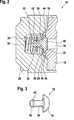
Nachfolgend wird ein Ausführungsbeispiel der erfindungsgemäßen Lösung anhand der beigefügten schematischen Zeichnungen näher erläutert. Es zeigt:An exemplary embodiment of the solution according to the invention will be explained in more detail below with reference to the attached schematic drawings. It shows:
In
Die
Auf diese Weise ist eine Konstruktion geschaffen, mit der Fertigungsmaßtoleranzen insbesondere zwischen dem Dichtsitz
Das Schließelement
Das Schließelement
An der dem Schließelement
In dem Kanal
Zum Einfügen des Schließelements
In den
ZITATE ENTHALTEN IN DER BESCHREIBUNG QUOTES INCLUDE IN THE DESCRIPTION
Diese Liste der vom Anmelder aufgeführten Dokumente wurde automatisiert erzeugt und ist ausschließlich zur besseren Information des Lesers aufgenommen. Die Liste ist nicht Bestandteil der deutschen Patent- bzw. Gebrauchsmusteranmeldung. Das DPMA übernimmt keinerlei Haftung für etwaige Fehler oder Auslassungen.This list of the documents listed by the applicant has been generated automatically and is included solely for the better information of the reader. The list is not part of the German patent or utility model application. The DPMA assumes no liability for any errors or omissions.
Zitierte PatentliteraturCited patent literature
- DE 19928913 A1[0002]DE 19928913 A1[0002]
Claims (10)
Translated fromGermanPriority Applications (8)
| Application Number | Priority Date | Filing Date | Title |
|---|---|---|---|
| DE102010039501ADE102010039501A1 (en) | 2010-08-19 | 2010-08-19 | Valve of a piston pump with a closing body |
| JP2013524389AJP5677574B2 (en) | 2010-08-19 | 2011-06-21 | Piston pump valve with closure |
| ES11727687TES2732352T3 (en) | 2010-08-19 | 2011-06-21 | Valve of a piston pump with a closing body |
| EP11727687.3AEP2606233B1 (en) | 2010-08-19 | 2011-06-21 | Valve of a piston pump with a closing body |
| CN201180040047.5ACN103080552B (en) | 2010-08-19 | 2011-06-21 | Valves for piston pumps with closures |
| KR1020137003978AKR101876781B1 (en) | 2010-08-19 | 2011-06-21 | Valve of a piston pump with a closing body |
| US13/817,549US9982671B2 (en) | 2010-08-19 | 2011-06-21 | Valve of a piston pump with a closing body |
| PCT/EP2011/060340WO2012022522A1 (en) | 2010-08-19 | 2011-06-21 | Valve of a piston pump with a closing body |
Applications Claiming Priority (1)
| Application Number | Priority Date | Filing Date | Title |
|---|---|---|---|
| DE102010039501ADE102010039501A1 (en) | 2010-08-19 | 2010-08-19 | Valve of a piston pump with a closing body |
Publications (1)
| Publication Number | Publication Date |
|---|---|
| DE102010039501A1true DE102010039501A1 (en) | 2012-02-23 |
Family
ID=44543966
Family Applications (1)
| Application Number | Title | Priority Date | Filing Date |
|---|---|---|---|
| DE102010039501ACeasedDE102010039501A1 (en) | 2010-08-19 | 2010-08-19 | Valve of a piston pump with a closing body |
Country Status (8)
| Country | Link |
|---|---|
| US (1) | US9982671B2 (en) |
| EP (1) | EP2606233B1 (en) |
| JP (1) | JP5677574B2 (en) |
| KR (1) | KR101876781B1 (en) |
| CN (1) | CN103080552B (en) |
| DE (1) | DE102010039501A1 (en) |
| ES (1) | ES2732352T3 (en) |
| WO (1) | WO2012022522A1 (en) |
Cited By (5)
| Publication number | Priority date | Publication date | Assignee | Title |
|---|---|---|---|---|
| DE102014212501A1 (en) | 2014-06-27 | 2015-12-31 | Robert Bosch Gmbh | Valve of a piston pump with a two-part closing body |
| DE102014214886A1 (en) | 2014-07-29 | 2016-02-04 | Volkswagen Aktiengesellschaft | Double-acting check valve |
| DE102014214887A1 (en) | 2014-07-29 | 2016-02-04 | Volkswagen Aktiengesellschaft | Steamed check valve |
| WO2018122005A1 (en)* | 2016-12-27 | 2018-07-05 | Robert Bosch Gmbh | Pump unit for feeding fuel, preferably diesel fuel, to an internal combustion engine |
| DE102022208474A1 (en)* | 2022-08-15 | 2024-02-15 | Continental Automotive Technologies GmbH | Valve assembly for a hydraulic unit and hydraulic unit |
Families Citing this family (4)
| Publication number | Priority date | Publication date | Assignee | Title |
|---|---|---|---|---|
| DE102011082585B4 (en)* | 2011-09-13 | 2024-03-07 | Robert Bosch Gmbh | Damping device of a hydraulic unit |
| US10156293B1 (en)* | 2017-07-18 | 2018-12-18 | GM Global Technology Operations LLC | Fluid pump pressure relief valve |
| CN109140041B (en)* | 2018-10-19 | 2024-07-19 | 惠州海卓科赛医疗有限公司 | Valve plug, high-pressure pump structure and valve plug sealing method |
| DE102019215988A1 (en) | 2019-10-17 | 2021-04-22 | Continental Teves Ag & Co. Ohg | Pulsation damper |
Citations (1)
| Publication number | Priority date | Publication date | Assignee | Title |
|---|---|---|---|---|
| DE19928913A1 (en) | 1999-06-24 | 2001-01-04 | Bosch Gmbh Robert | Piston pump |
Family Cites Families (13)
| Publication number | Priority date | Publication date | Assignee | Title |
|---|---|---|---|---|
| US1939128A (en)* | 1929-03-25 | 1933-12-12 | F C Muren | Pump valve |
| US3332437A (en)* | 1965-02-18 | 1967-07-25 | Hallen Gosta | Valves |
| JPS5635622Y2 (en) | 1976-04-23 | 1981-08-21 | ||
| JPS6344610Y2 (en)* | 1981-03-14 | 1988-11-18 | ||
| JPH0198773A (en)* | 1987-09-22 | 1989-04-17 | Yoshinobu Koiwa | Valve device |
| KR100589026B1 (en)* | 1997-11-14 | 2006-06-13 | 콘티넨탈 테베스 아게 운트 코. 오하게 | Piston pump |
| DE19800500A1 (en)* | 1998-01-09 | 1999-07-15 | Bosch Gmbh Robert | Piston pump |
| CN2403604Y (en)* | 2000-01-14 | 2000-11-01 | 上海同捷科技有限公司 | Vibration-damper valve |
| US7004733B2 (en)* | 2001-06-30 | 2006-02-28 | Robert Bosch Gmbh | Piston pump |
| DE102007052664A1 (en)* | 2007-11-05 | 2009-05-07 | Robert Bosch Gmbh | Guide ring for a piston pump and piston pump |
| DE102008002740A1 (en)* | 2008-06-27 | 2009-12-31 | Robert Bosch Gmbh | piston pump |
| DE102008060146A1 (en)* | 2008-12-03 | 2010-06-17 | Thyssenkrupp Presta Ag | Check valve for a hydraulic power steering |
| CN201511774U (en)* | 2009-08-06 | 2010-06-23 | 宣昌黎 | Energy-saving vibration absorber of car |
- 2010
- 2010-08-19DEDE102010039501Apatent/DE102010039501A1/ennot_activeCeased
- 2011
- 2011-06-21CNCN201180040047.5Apatent/CN103080552B/enactiveActive
- 2011-06-21WOPCT/EP2011/060340patent/WO2012022522A1/enactiveApplication Filing
- 2011-06-21JPJP2013524389Apatent/JP5677574B2/enactiveActive
- 2011-06-21ESES11727687Tpatent/ES2732352T3/enactiveActive
- 2011-06-21EPEP11727687.3Apatent/EP2606233B1/enactiveActive
- 2011-06-21USUS13/817,549patent/US9982671B2/enactiveActive
- 2011-06-21KRKR1020137003978Apatent/KR101876781B1/enactiveActive
Patent Citations (1)
| Publication number | Priority date | Publication date | Assignee | Title |
|---|---|---|---|---|
| DE19928913A1 (en) | 1999-06-24 | 2001-01-04 | Bosch Gmbh Robert | Piston pump |
Cited By (9)
| Publication number | Priority date | Publication date | Assignee | Title |
|---|---|---|---|---|
| DE102014212501A1 (en) | 2014-06-27 | 2015-12-31 | Robert Bosch Gmbh | Valve of a piston pump with a two-part closing body |
| US11007990B2 (en) | 2014-06-27 | 2021-05-18 | Robert Bosch Gmbh | Valve of a piston pump having a two-part closing body |
| DE102014214886A1 (en) | 2014-07-29 | 2016-02-04 | Volkswagen Aktiengesellschaft | Double-acting check valve |
| DE102014214887A1 (en) | 2014-07-29 | 2016-02-04 | Volkswagen Aktiengesellschaft | Steamed check valve |
| DE102014214886B4 (en)* | 2014-07-29 | 2017-12-14 | Volkswagen Aktiengesellschaft | Double-acting check valve |
| DE102014214887B4 (en)* | 2014-07-29 | 2017-12-14 | Volkswagen Aktiengesellschaft | Steamed check valve |
| WO2018122005A1 (en)* | 2016-12-27 | 2018-07-05 | Robert Bosch Gmbh | Pump unit for feeding fuel, preferably diesel fuel, to an internal combustion engine |
| US10954907B2 (en) | 2016-12-27 | 2021-03-23 | Robert Bosch Gmbh | Pump unit for feeding fuel, preferably diesel fuel, to an internal combustion engine |
| DE102022208474A1 (en)* | 2022-08-15 | 2024-02-15 | Continental Automotive Technologies GmbH | Valve assembly for a hydraulic unit and hydraulic unit |
Also Published As
| Publication number | Publication date |
|---|---|
| WO2012022522A1 (en) | 2012-02-23 |
| CN103080552A (en) | 2013-05-01 |
| JP2013538968A (en) | 2013-10-17 |
| ES2732352T3 (en) | 2019-11-22 |
| KR101876781B1 (en) | 2018-07-10 |
| JP5677574B2 (en) | 2015-02-25 |
| EP2606233B1 (en) | 2019-03-27 |
| CN103080552B (en) | 2016-05-18 |
| EP2606233A1 (en) | 2013-06-26 |
| KR20130137132A (en) | 2013-12-16 |
| US9982671B2 (en) | 2018-05-29 |
| US20130240773A1 (en) | 2013-09-19 |
Similar Documents
| Publication | Publication Date | Title |
|---|---|---|
| EP2606233B1 (en) | Valve of a piston pump with a closing body | |
| EP1934405B1 (en) | Sanitary installation part | |
| DE102010000901B4 (en) | Solenoid valve and driver assistance device | |
| DE202012012978U1 (en) | Butterfly valve | |
| DE102014205496A1 (en) | Electromagnetically actuated gas valve and method for increasing the tightness of an electromagnetically actuated gas valve | |
| DE102008057393A1 (en) | Check valve in cartridge design | |
| DE102012208591A1 (en) | Control valve for a hydraulic device | |
| DE102006025027A1 (en) | Piston pump for transporting fluid for vehicle braking system has integral annular sealing region with separating point for sealing pressure chamber with respect to low pressure region | |
| DE102012221543A1 (en) | valve means | |
| DE202016102245U1 (en) | Cage assembly with throttle rings | |
| DE102011087103A1 (en) | Master cylinder | |
| DE102014212501A1 (en) | Valve of a piston pump with a two-part closing body | |
| EP3414436A1 (en) | Exhaust gas outlet system for a motor vehicle, motor vehicle having such an exhaust gas outlet system, and method for producing an exhaust gas outlet system | |
| DE102010062174A1 (en) | Valve, in particular an outlet valve of a hydraulic piston pump | |
| EP3236033B1 (en) | Combination valve for filling and venting of a liquid reservoir | |
| DE102013206461A1 (en) | Fixing clip, esp. For a motor vehicle | |
| DE102013223754A1 (en) | Ventilation device for a hydraulic system | |
| DE102018114249A1 (en) | ELECTROMAGNETIC VALVE ARRANGEMENT | |
| DE102006029823B3 (en) | Valve for regulation of the flow of a fluid medium through a heating system or a cooling system has axial pressure-relief slit | |
| DE102013200399B4 (en) | Central screw with a valve for a camshaft adjuster | |
| DE102014208639A1 (en) | valve assembly | |
| DE102012223119A1 (en) | Cylinder of a piston pump of a vehicle brake system | |
| EP3135917B1 (en) | Vacuum pump | |
| DE102005039640A1 (en) | Magnetic valve for use in hydraulic or pneumatic system, has valve unit detachably connected with housing, and spring plate engaged with inner edge so that coil unit is axially clamped between free end and housing | |
| DE102018112928A1 (en) | Compact venting module; Actuating device and coupling system |
Legal Events
| Date | Code | Title | Description |
|---|---|---|---|
| R012 | Request for examination validly filed | ||
| R002 | Refusal decision in examination/registration proceedings | ||
| R003 | Refusal decision now final |