DE102010039008A1 - Rotor and manufacturing process for this purpose - Google Patents
Rotor and manufacturing process for this purposeDownload PDFInfo
- Publication number
- DE102010039008A1 DE102010039008A1DE102010039008ADE102010039008ADE102010039008A1DE 102010039008 A1DE102010039008 A1DE 102010039008A1DE 102010039008 ADE102010039008 ADE 102010039008ADE 102010039008 ADE102010039008 ADE 102010039008ADE 102010039008 A1DE102010039008 A1DE 102010039008A1
- Authority
- DE
- Germany
- Prior art keywords
- rotor
- rotor shaft
- structural elements
- laminated core
- surface area
- Prior art date
- Legal status (The legal status is an assumption and is not a legal conclusion. Google has not performed a legal analysis and makes no representation as to the accuracy of the status listed.)
- Pending
Links
- 238000004519manufacturing processMethods0.000titleclaimsabstractdescription21
- 238000000034methodMethods0.000claimsdescription6
- 238000005516engineering processMethods0.000abstractdescription6
- 238000006073displacement reactionMethods0.000description5
- 230000035508accumulationEffects0.000description4
- 238000009825accumulationMethods0.000description4
- 230000015572biosynthetic processEffects0.000description2
- 230000001419dependent effectEffects0.000description1
- 230000006698inductionEffects0.000description1
- 238000003780insertionMethods0.000description1
- 230000037431insertionEffects0.000description1
- 230000003993interactionEffects0.000description1
- 238000003475laminationMethods0.000description1
- 238000003754machiningMethods0.000description1
- 238000002360preparation methodMethods0.000description1
Images


Classifications
- H—ELECTRICITY
- H02—GENERATION; CONVERSION OR DISTRIBUTION OF ELECTRIC POWER
- H02K—DYNAMO-ELECTRIC MACHINES
- H02K1/00—Details of the magnetic circuit
- H02K1/06—Details of the magnetic circuit characterised by the shape, form or construction
- H02K1/22—Rotating parts of the magnetic circuit
- H02K1/28—Means for mounting or fastening rotating magnetic parts on to, or to, the rotor structures
- F—MECHANICAL ENGINEERING; LIGHTING; HEATING; WEAPONS; BLASTING
- F16—ENGINEERING ELEMENTS AND UNITS; GENERAL MEASURES FOR PRODUCING AND MAINTAINING EFFECTIVE FUNCTIONING OF MACHINES OR INSTALLATIONS; THERMAL INSULATION IN GENERAL
- F16C—SHAFTS; FLEXIBLE SHAFTS; ELEMENTS OR CRANKSHAFT MECHANISMS; ROTARY BODIES OTHER THAN GEARING ELEMENTS; BEARINGS
- F16C3/00—Shafts; Axles; Cranks; Eccentrics
- F16C3/02—Shafts; Axles
- F—MECHANICAL ENGINEERING; LIGHTING; HEATING; WEAPONS; BLASTING
- F16—ENGINEERING ELEMENTS AND UNITS; GENERAL MEASURES FOR PRODUCING AND MAINTAINING EFFECTIVE FUNCTIONING OF MACHINES OR INSTALLATIONS; THERMAL INSULATION IN GENERAL
- F16D—COUPLINGS FOR TRANSMITTING ROTATION; CLUTCHES; BRAKES
- F16D1/00—Couplings for rigidly connecting two coaxial shafts or other movable machine elements
- F16D1/06—Couplings for rigidly connecting two coaxial shafts or other movable machine elements for attachment of a member on a shaft or on a shaft-end
- F16D1/064—Couplings for rigidly connecting two coaxial shafts or other movable machine elements for attachment of a member on a shaft or on a shaft-end non-disconnectable
- F16D1/072—Couplings for rigidly connecting two coaxial shafts or other movable machine elements for attachment of a member on a shaft or on a shaft-end non-disconnectable involving plastic deformation
- F—MECHANICAL ENGINEERING; LIGHTING; HEATING; WEAPONS; BLASTING
- F16—ENGINEERING ELEMENTS AND UNITS; GENERAL MEASURES FOR PRODUCING AND MAINTAINING EFFECTIVE FUNCTIONING OF MACHINES OR INSTALLATIONS; THERMAL INSULATION IN GENERAL
- F16D—COUPLINGS FOR TRANSMITTING ROTATION; CLUTCHES; BRAKES
- F16D2300/00—Special features for couplings or clutches
- F16D2300/10—Surface characteristics; Details related to material surfaces
- H—ELECTRICITY
- H02—GENERATION; CONVERSION OR DISTRIBUTION OF ELECTRIC POWER
- H02K—DYNAMO-ELECTRIC MACHINES
- H02K7/00—Arrangements for handling mechanical energy structurally associated with dynamo-electric machines, e.g. structural association with mechanical driving motors or auxiliary dynamo-electric machines
- H02K7/003—Couplings; Details of shafts
- Y—GENERAL TAGGING OF NEW TECHNOLOGICAL DEVELOPMENTS; GENERAL TAGGING OF CROSS-SECTIONAL TECHNOLOGIES SPANNING OVER SEVERAL SECTIONS OF THE IPC; TECHNICAL SUBJECTS COVERED BY FORMER USPC CROSS-REFERENCE ART COLLECTIONS [XRACs] AND DIGESTS
- Y10—TECHNICAL SUBJECTS COVERED BY FORMER USPC
- Y10T—TECHNICAL SUBJECTS COVERED BY FORMER US CLASSIFICATION
- Y10T29/00—Metal working
- Y10T29/49—Method of mechanical manufacture
- Y10T29/49002—Electrical device making
- Y10T29/49009—Dynamoelectric machine
- Y10T29/49011—Commutator or slip ring assembly
- Y—GENERAL TAGGING OF NEW TECHNOLOGICAL DEVELOPMENTS; GENERAL TAGGING OF CROSS-SECTIONAL TECHNOLOGIES SPANNING OVER SEVERAL SECTIONS OF THE IPC; TECHNICAL SUBJECTS COVERED BY FORMER USPC CROSS-REFERENCE ART COLLECTIONS [XRACs] AND DIGESTS
- Y10—TECHNICAL SUBJECTS COVERED BY FORMER USPC
- Y10T—TECHNICAL SUBJECTS COVERED BY FORMER US CLASSIFICATION
- Y10T29/00—Metal working
- Y10T29/49—Method of mechanical manufacture
- Y10T29/49002—Electrical device making
- Y10T29/49009—Dynamoelectric machine
- Y10T29/49012—Rotor
- Y—GENERAL TAGGING OF NEW TECHNOLOGICAL DEVELOPMENTS; GENERAL TAGGING OF CROSS-SECTIONAL TECHNOLOGIES SPANNING OVER SEVERAL SECTIONS OF THE IPC; TECHNICAL SUBJECTS COVERED BY FORMER USPC CROSS-REFERENCE ART COLLECTIONS [XRACs] AND DIGESTS
- Y10—TECHNICAL SUBJECTS COVERED BY FORMER USPC
- Y10T—TECHNICAL SUBJECTS COVERED BY FORMER US CLASSIFICATION
- Y10T403/00—Joints and connections
- Y10T403/48—Shrunk fit
- Y—GENERAL TAGGING OF NEW TECHNOLOGICAL DEVELOPMENTS; GENERAL TAGGING OF CROSS-SECTIONAL TECHNOLOGIES SPANNING OVER SEVERAL SECTIONS OF THE IPC; TECHNICAL SUBJECTS COVERED BY FORMER USPC CROSS-REFERENCE ART COLLECTIONS [XRACs] AND DIGESTS
- Y10—TECHNICAL SUBJECTS COVERED BY FORMER USPC
- Y10T—TECHNICAL SUBJECTS COVERED BY FORMER US CLASSIFICATION
- Y10T403/00—Joints and connections
- Y10T403/49—Member deformed in situ
- Y10T403/4991—Both members deformed
Landscapes
- Engineering & Computer Science (AREA)
- General Engineering & Computer Science (AREA)
- Mechanical Engineering (AREA)
- Ocean & Marine Engineering (AREA)
- Power Engineering (AREA)
- Iron Core Of Rotating Electric Machines (AREA)
- Manufacture Of Motors, Generators (AREA)
Abstract
Translated fromGermanDescription
Translated fromGermanDie Erfindung betrifft einen Rotor mit einer Rotorwelle, durch die eine Rotorachse festgelegt ist sowie mit einem Blechpaket, das entlang eines Längsabschnitts der Rotorachse um die Rotorwelle herum angeordnet ist. Weiterhin betrifft die Erfindung ein Herstellungsverfahren für einen solchen Rotor.The invention relates to a rotor having a rotor shaft, through which a rotor axis is fixed and with a laminated core which is arranged along a longitudinal section of the rotor axis around the rotor shaft. Furthermore, the invention relates to a manufacturing method for such a rotor.
Bei einem solchen Rotor ist in der Regel erwünscht bzw. gefordert, dass das Blechpaket so fest mit der Rotorwelle verbunden ist, dass es bei einem regulären Einsatz des Rotors, also beispielsweise als Element eines Elektromotors, zu keiner Relativdrehung zwischen dem Blechpaket und der Rotorwelle kommen kann.In such a rotor is usually desired or required that the laminated core is so firmly connected to the rotor shaft, that there is no relative rotation between the laminated core and the rotor shaft at a regular use of the rotor, so for example as an element of an electric motor can.
Zur Herstellung eines solchen Rotors ist es bekannt, das Blechpaket auf die Rotorwelle aufzuschrumpfen. Dies ist jedoch vergleichsweise zeit- und kostenaufwändig. Insbesondere erfordert dieses Verfahren eine umfangreiche spanende Bearbeitung der Rotorwelle vor dem Aufschrumpfen.For producing such a rotor, it is known to shrink the laminated core onto the rotor shaft. However, this is relatively time consuming and costly. In particular, this method requires extensive machining of the rotor shaft prior to shrinking.
Der Erfindung liegt die Aufgabe zugrunde, einen entsprechenden Rotor anzugeben, der sich einfacher herstellen lässt sowie ein Herstellungsverfahren für einen solchen Rotor.The invention has for its object to provide a corresponding rotor, which is easier to manufacture and a manufacturing method for such a rotor.
Diese Aufgabe wird gemäß der Erfindung mit den in den unabhängigen Ansprüchen genannten Gegenständen gelöst. Besondere Ausführungsarten der Erfindung sind in den abhängigen Ansprüchen angegeben.This object is achieved according to the invention with the objects mentioned in the independent claims. Particular embodiments of the invention are indicated in the dependent claims.
Gemäß der Erfindung ist ein Rotor vorgesehen, der eine Rotorwelle aufweist, durch die eine Rotorachse festgelegt ist sowie ein Blechpaket, das entlang eines Längsabschnitts der Rotorachse um die Rotorwelle herum angeordnet ist. Entlang des Längsabschnitts weist die Rotorwelle einen ersten Oberflächenbereich auf, dessen Form einen Kreiszylinder beschreibt sowie einen zweiten Oberflächenbereich, der durch Strukturelemente gebildet ist, die sich mit Bezug auf die Rotorachse radial nach außen über den ersten Oberflächenbereich erheben.According to the invention, a rotor is provided, which has a rotor shaft, through which a rotor axis is fixed, and a laminated core which is arranged along a longitudinal section of the rotor axis around the rotor shaft. Along the longitudinal section, the rotor shaft has a first surface area, the shape of which describes a circular cylinder, and a second surface area formed by structural elements which rise radially outward with respect to the rotor axis over the first surface area.
Zur Herstellung des Rotors lässt sich das Blechpaket über die Rotorwelle schieben und dabei derart gegen die Strukturelemente drücken, dass das Blechpaket plastisch verformt und hierdurch eine Formschlussverbindung zwischen der Rotorwelle und dem Blechpaket erzeugt wird. Auf diese Weise lässt sich herstellungstechnisch besonders einfach eine zuverlässige bzw. verdrehsichere Verbindung zwischen dem Blechpaket und der Rotorwelle bilden. Es lässt sich mit anderen Worten ein umformtechnisch hergestellter Formschluss erzeugen.To produce the rotor, the laminated core can be pushed over the rotor shaft and in this way press against the structural elements such that the laminated core is plastically deformed and as a result a form-locking connection is produced between the rotor shaft and the laminated core. In this way, manufacturing technology makes it particularly easy to form a reliable or rotationally secure connection between the laminated core and the rotor shaft. In other words, it is possible to produce a positive fit produced by forming technology.
Wenn die Strukturelemente parallel zur Rotorachse ausgebildet sind, lässt sich bei der Herstellung des Rotors das Blechpaket ohne Rotation um die Rotorwelle über die Rotorwelle schieben; hierdurch lassen sich Verformungen des Blechpakets erzeugen, die ebenfalls entsprechend parallel zur Rotorwelle ausgebildet sind, so dass ein besonders zuverlässiger Formschluss gebildet ist.If the structural elements are formed parallel to the rotor axis, can be in the manufacture of the rotor, the laminated core without rotation about the rotor shaft to push over the rotor shaft; As a result, deformations of the laminated core can be produced, which are also formed correspondingly parallel to the rotor shaft, so that a particularly reliable positive connection is formed.
Vorteilhaft sind die Strukturelemente derart ausgebildet, dass sie sich längs der Rotorachse über mindestens die Hälfte, vorzugsweise mindestens zwei Drittel, besonders bevorzugt mindestens drei Viertel des Längsabschnitts erstrecken. Auf diese Weise lässt sich ein vergleichsweise großflächiger Formschlussbereich und somit ein besonders zuverlässiger Formschluss herstellen.Advantageously, the structural elements are designed such that they extend along the rotor axis over at least half, preferably at least two thirds, more preferably at least three quarters of the longitudinal section. In this way, a comparatively large-area positive-locking region and thus a particularly reliable positive connection can be produced.
Besonders vorteilhaft sind zwischen drei und hundert, vorzugsweise zwischen fünf und fünfzig Strukturelemente vorhanden, die gleichmäßig über den Umfang der Rotorwelle angeordnet sind.Particularly advantageous are between three and a hundred, preferably between five and fifty structural elements present, which are arranged uniformly over the circumference of the rotor shaft.
Als vorteilhaft hat es sich erwiesen, wenn die Strukturelemente mit Bezug auf den Kreiszylinder eine maximale Höhe aufweisen, die zwischen 0,05 und 5 mm, vorzugsweise zwischen 0,1 und 2 mm beträgt.It has proved to be advantageous if the structural elements with respect to the circular cylinder have a maximum height which is between 0.05 and 5 mm, preferably between 0.1 and 2 mm.
Vorteilhaft weisen die Strukturelemente in einem Schnitt quer zur Rotorachse jeweils eine nach außen gewölbte Form auf. Dies begünstigt bei der Herstellung eine Materialverschiebung des Blechpakets, die zu einer besonders zuverlässigen Formschlussverbindung führt.Advantageously, the structural elements in a section transverse to the rotor axis each have an outwardly curved shape. This favors in the production of a material displacement of the laminated core, which leads to a particularly reliable positive connection.
Weiterhin vorzugsweise ist die Ausgestaltung der Rotorwelle derart, dass – in einem Schnitt quer zur Rotationsachse betrachtet – diejenigen Winkelbereiche, die von dem ersten Oberflächenbereich überdeckt sind, größer sind, vorzugsweise wenigstens eineinhalb mal so groß sind wie diejenigen weiteren Winkelbereiche, die von dem zweiten Oberflächenbereich überdeckt sind. Auf diese Weise kann zwischen zwei benachbarten Strukturelementen reichlich Raum zur Aufnahme von verschobenem Material des Blechpakets gewährleistet werden, was wiederum der Stabilität der Formschlussverbindung förderlich ist.Further preferably, the configuration of the rotor shaft is such that - viewed in a section transverse to the axis of rotation - those angular ranges which are covered by the first surface area are larger, preferably at least one and a half times as large as those other angular ranges, that of the second surface area are covered. In this way, ample space for receiving displaced material of the laminated core can be ensured between two adjacent structural elements, which in turn is conducive to the stability of the positive connection.
Gemäß einem weiteren Aspekt der Erfindung ist ein Elektromotor vorgesehen, der einen erfindungsgemäßen Rotor aufweist.According to a further aspect of the invention, an electric motor is provided which has a rotor according to the invention.
Gemäß einem noch weiteren Aspekt der Erfindung ist ein Verfahren zur Herstellung eines Rotors vorgesehen, der eine Rotorwelle aufweist, durch die eine Rotorachse festgelegt ist sowie ein Blechpaket, das entlang eines Längsabschnitts der Rotorachse um die Rotorwelle herum angeordnet ist. Die Rotorwelle weist dabei entlang des Längsabschnitts einen ersten Oberflächenbereich auf, dessen Form einen Kreiszylinder beschreibt sowie einen zweiten Oberflächenbereich, der durch Strukturelemente gebildet ist, die sich mit Bezug auf die Rotorachse radial nach außen über den ersten Oberflächenbereich erheben. Zur Verbindung des Blechpakets mit der Rotorwelle wird das Blechpaket derart gegen die Strukturelemente gedrückt, dass das Blechpaket hierdurch eine Verformung erfährt.According to yet another aspect of the invention, there is provided a method of manufacturing a rotor having a rotor shaft defining a rotor axis and a lamination stack disposed along a longitudinal portion of the rotor axis about the rotor shaft. The rotor shaft points along the longitudinal section a first surface area, the shape of which describes a circular cylinder, and a second surface area formed by structural elements that rise radially outwardly beyond the first surface area with respect to the rotor axis. To connect the laminated core to the rotor shaft, the laminated core is pressed against the structural elements in such a way that the laminated core thereby undergoes deformation.
Vorteilhaft werden die Strukturelemente der Rotorwelle im Rahmen der Herstellung der Rotorwelle durch ein Umformen gebildet.Advantageously, the structural elements of the rotor shaft are formed by forming in the context of the manufacture of the rotor shaft.
Weiterhin vorteilhaft wird im Rahmen der Herstellung des Blechpakets das Blechpaket mit einer Bohrung zur Aufnahme der Rotorwelle versehen, so dass das Blechpaket einen runden Innendurchmesser aufweist. Dabei weist die Bohrung einen Bohrungsradius auf, der um ein kleines Maß größer ist als der Radius des Kreiszylinders, wobei das kleine Maß kleiner oder gleich der maximalen Höhe der Strukturelemente mit Bezug auf den Kreiszylinder ist. Auf diese Weise steht zwischen den Strukturelementen besonders geeigneter Raum für die Verformung des Blechpakets zur Verfügung; dies trägt dazu bei, dass sich eine besonders zuverlässige Verbindung zwischen dem Blechpaket und der Rotorwelle ausbilden kann.Further advantageously, in the context of the production of the laminated core, the laminated core is provided with a bore for receiving the rotor shaft, so that the laminated core has a round inner diameter. In this case, the bore has a bore radius which is larger by a small amount than the radius of the circular cylinder, wherein the small amount is less than or equal to the maximum height of the structural elements with respect to the circular cylinder. In this way, between the structural elements particularly suitable space for the deformation of the laminated core is available; This contributes to the fact that a particularly reliable connection between the laminated core and the rotor shaft can form.
Bevorzugt beträgt dabei das kleine Maß zwischen 0,001 mm und 2 mm, vorzugsweise zwischen 0,01 mm und 1 mm.The small dimension is preferably between 0.001 mm and 2 mm, preferably between 0.01 mm and 1 mm.
Vorteilhaft handelt es sich bei dem Verfahren um ein Verfahren zur Herstellung eines erfindungsgemäßen Rotors.Advantageously, the method is a method for producing a rotor according to the invention.
Die Erfindung wird im Folgenden anhand eines Ausführungsbeispiels und mit Bezug auf die Zeichnungen näher erläutert. Es zeigen:The invention is explained in more detail below with reference to an embodiment and with reference to the drawings. Show it:
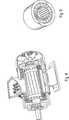
Ein erfindungsgemäßer Rotor eignet sich beispielsweise als Rotor eines Elektromotors, wie er beispielhaft in
In
Zur Verbindung des Blechpakets
Herstellungstechnisch vorteilhaft werden dabei die Strukturelemente
In
Wie beispielhaft in den
Es kann vorgesehen sein, dass die Strukturelemente
Insbesondere kann vorgesehen sein, dass die Strukturelemente
Beispielsweise können insgesamt zwischen drei und hundert, vorzugsweise zwischen fünf und fünfzig Strukturelemente
Vorteilhaft mit Bezug auf die Materialverschiebung des Blechpakets
Auch können die Strukturelemente
Es kann vorgesehen sein, dass die Strukturelemente
Zur Herstellung kann vorgesehen sein, dass das Blechpaket
Weiterhin kann die Ausgestaltung der Rotorwelle
Schließlich ist gemäß der Erfindung ein Elektromotor mit einem erfindungsgemäßen Rotor vorgesehen.Finally, according to the invention, an electric motor is provided with a rotor according to the invention.
Der erfindungsgemäße Rotor lässt sich besonders einfach herstellen, also mit besonders niedrigen Herstellungs- und Fertigungskosten und bietet dabei dennoch eine zuverlässige verdrehsichere Verbindung zwischen der Rotorwelle und dem Blechpaket. Die Verbindung wird durch einen umformtechnisch erzeugten Formschluss sichergestellt.The rotor according to the invention can be produced in a particularly simple manner, that is to say with particularly low manufacturing and production costs, while nevertheless offering a reliable, torsion-proof connection between the rotor shaft and the laminated core. The connection is ensured by a positive connection generated by forming technology.
Claims (13)
Translated fromGermanPriority Applications (3)
| Application Number | Priority Date | Filing Date | Title |
|---|---|---|---|
| DE102010039008ADE102010039008A1 (en) | 2010-08-06 | 2010-08-06 | Rotor and manufacturing process for this purpose |
| US13/178,630US8847462B2 (en) | 2010-08-06 | 2011-07-08 | Rotor and process for producing the same |
| JP2011171900AJP5856404B2 (en) | 2010-08-06 | 2011-08-05 | Rotor, rotor manufacturing method, and electric motor having the rotor |
Applications Claiming Priority (1)
| Application Number | Priority Date | Filing Date | Title |
|---|---|---|---|
| DE102010039008ADE102010039008A1 (en) | 2010-08-06 | 2010-08-06 | Rotor and manufacturing process for this purpose |
Publications (1)
| Publication Number | Publication Date |
|---|---|
| DE102010039008A1true DE102010039008A1 (en) | 2012-02-09 |
Family
ID=45495046
Family Applications (1)
| Application Number | Title | Priority Date | Filing Date |
|---|---|---|---|
| DE102010039008APendingDE102010039008A1 (en) | 2010-08-06 | 2010-08-06 | Rotor and manufacturing process for this purpose |
Country Status (3)
| Country | Link |
|---|---|
| US (1) | US8847462B2 (en) |
| JP (1) | JP5856404B2 (en) |
| DE (1) | DE102010039008A1 (en) |
Cited By (8)
| Publication number | Priority date | Publication date | Assignee | Title |
|---|---|---|---|---|
| DE102016118026A1 (en) | 2016-09-23 | 2018-03-29 | Hirschvogel Umformtechnik Gmbh | Rotor, in particular rotor for an electric machine, electric machine and method for producing a rotor |
| DE102018122977A1 (en)* | 2018-09-19 | 2020-03-19 | Muhr Und Bender Kg | Shaft arrangement |
| DE102020111680A1 (en) | 2020-04-29 | 2021-11-04 | Valeo Siemens Eautomotive Germany Gmbh | Forming device for manufacturing a knurled rotor shaft, method for manufacturing a rotor shaft for an electrical machine, rotor shaft, rotor and method for vibration analysis of a rotor |
| EP3625879B1 (en) | 2017-05-16 | 2022-03-30 | Mavel EDT S.p.A. | Electric machine comprising a knurled rotor shaft and method for manufacturing such a machine |
| DE102021111191A1 (en) | 2021-04-30 | 2022-11-03 | Dr. Ing. H.C. F. Porsche Aktiengesellschaft | Joining tool for pressing a disk with a shaft and rotor shaft for an electrical machine |
| DE102021205713A1 (en) | 2021-05-31 | 2022-12-01 | Valeo Eautomotive Germany Gmbh | Rotor for an electric machine |
| DE102022003866A1 (en)* | 2022-10-19 | 2024-04-25 | Hirschvogel Holding GmbH | Rotor shaft assembly, rotor, electric machine and manufacturing method for a rotor shaft |
| DE102023104257A1 (en) | 2023-02-21 | 2024-08-22 | Dr. Ing. H.C. F. Porsche Aktiengesellschaft | Shaft-hub connection of an electric motor and method for producing a shaft-hub connection |
Families Citing this family (11)
| Publication number | Priority date | Publication date | Assignee | Title |
|---|---|---|---|---|
| DE102010039008A1 (en)* | 2010-08-06 | 2012-02-09 | Hirschvogel Umformtechnik Gmbh | Rotor and manufacturing process for this purpose |
| DE102013002181B4 (en) | 2012-02-15 | 2021-03-25 | Denso Corporation | Rotor and motor |
| JP5814159B2 (en)* | 2012-03-05 | 2015-11-17 | アスモ株式会社 | Rotor and motor |
| CN103259365B (en)* | 2012-02-17 | 2018-01-16 | 德昌电机(深圳)有限公司 | drive device |
| KR101437946B1 (en)* | 2013-08-09 | 2014-09-16 | (주)에이치에스지 | Rotor balance structure for interior permanant magnet motor |
| TWI534367B (en)* | 2014-11-28 | 2016-05-21 | Dtech Prec Ind Co Ltd | Wheel structure and its application method |
| CN106712404A (en)* | 2017-01-20 | 2017-05-24 | 无锡金阳电机有限公司 | Motor rotor shaft assembly process |
| JP6816693B2 (en)* | 2017-10-11 | 2021-01-20 | トヨタ自動車株式会社 | Rotor and rotor manufacturing method |
| JP7191568B2 (en)* | 2018-07-23 | 2022-12-19 | ミネベアミツミ株式会社 | motor |
| CN109450129A (en)* | 2018-09-12 | 2019-03-08 | 贵州标准电机有限公司 | The fixation device of rotor in a kind of micromotor |
| US20220149685A1 (en)* | 2019-04-10 | 2022-05-12 | Pierburg Pump Technology Gmbh | Automotive auxiliary unit with an electric motor |
Family Cites Families (16)
| Publication number | Priority date | Publication date | Assignee | Title |
|---|---|---|---|---|
| GB642297A (en)* | 1948-09-21 | 1950-08-30 | Hoover Ltd | Improvements relating to the securing of shafts in synthetic resin mouldings |
| US2697795A (en)* | 1950-01-24 | 1954-12-21 | Redmond Company Inc | Dynamoelectric machine |
| JPS551924A (en)* | 1978-06-21 | 1980-01-09 | Hitachi Ltd | Joint structure of metal and its jointing method |
| JPS55117459A (en)* | 1979-03-05 | 1980-09-09 | Hitachi Ltd | Rotor of rotating-electric machine and its manufacturing method |
| JPS5698349A (en)* | 1980-01-07 | 1981-08-07 | Hitachi Ltd | Rotor of rotary electric machine and manufacture thereof |
| JPS56134110A (en)* | 1980-03-26 | 1981-10-20 | Hitachi Ltd | Internal diameter chuck for machine tool |
| US4809429A (en)* | 1986-09-29 | 1989-03-07 | Carbet Corporation | Apparatus for manufacturing laminated assemblies having ridges formed on projections which interlock with recesses of adjacent laminations |
| US4868392A (en)* | 1988-05-05 | 1989-09-19 | Wong Wai Hoi | Method of and apparatus for modulating the counts of a PET camera |
| DE10045222A1 (en)* | 2000-09-13 | 2002-04-04 | Bosch Gmbh Robert | Anchor for an electrical machine |
| DE10160847A1 (en)* | 2001-12-12 | 2003-07-17 | Valeo Auto Electric Gmbh | Actuating device, in particular for actuating limited slip differentials of vehicles |
| JPWO2004076095A1 (en)* | 2003-02-27 | 2006-06-01 | 株式会社ミツバ | Shaft and shaft forming equipment |
| JP2004343970A (en)* | 2003-05-19 | 2004-12-02 | Asmo Co Ltd | Armature structure for rotating electric machine |
| FR2884068B1 (en)* | 2005-03-31 | 2007-07-27 | Valeo Equip Electr Moteur | ROTOR OF ROTATING ELECTRIC MACHINE COMPRISING AN INTERMEDIATE SLEEVE INTERPOSED BETWEEN THE SHAFT AND POLAR WHEELS AND METHOD FOR PRODUCING THE ROTOR. |
| ES2349396T3 (en)* | 2005-06-20 | 2010-12-30 | Thyssenkrupp Presta Teccenter Ag | CAMSHAFT COMPOSITE. |
| JP2008092673A (en)* | 2006-10-02 | 2008-04-17 | Denso Corp | Rotor of ac generator for vehicle |
| DE102010039008A1 (en)* | 2010-08-06 | 2012-02-09 | Hirschvogel Umformtechnik Gmbh | Rotor and manufacturing process for this purpose |
- 2010
- 2010-08-06DEDE102010039008Apatent/DE102010039008A1/enactivePending
- 2011
- 2011-07-08USUS13/178,630patent/US8847462B2/enactiveActive
- 2011-08-05JPJP2011171900Apatent/JP5856404B2/enactiveActive
Cited By (12)
| Publication number | Priority date | Publication date | Assignee | Title |
|---|---|---|---|---|
| DE102016118026A1 (en) | 2016-09-23 | 2018-03-29 | Hirschvogel Umformtechnik Gmbh | Rotor, in particular rotor for an electric machine, electric machine and method for producing a rotor |
| DE102016118026B4 (en) | 2016-09-23 | 2022-01-27 | Hirschvogel Umformtechnik Gmbh | Rotor, in particular rotor for an electrical machine, electrical machine and method for producing a rotor |
| EP3625879B1 (en) | 2017-05-16 | 2022-03-30 | Mavel EDT S.p.A. | Electric machine comprising a knurled rotor shaft and method for manufacturing such a machine |
| DE102018122977A1 (en)* | 2018-09-19 | 2020-03-19 | Muhr Und Bender Kg | Shaft arrangement |
| WO2020058122A1 (en) | 2018-09-19 | 2020-03-26 | Muhr Und Bender Kg | Shaft assembly |
| US11946510B2 (en) | 2018-09-19 | 2024-04-02 | Muhr Und Bender Kg | Shaft assembly |
| DE102020111680A1 (en) | 2020-04-29 | 2021-11-04 | Valeo Siemens Eautomotive Germany Gmbh | Forming device for manufacturing a knurled rotor shaft, method for manufacturing a rotor shaft for an electrical machine, rotor shaft, rotor and method for vibration analysis of a rotor |
| DE102021111191A1 (en) | 2021-04-30 | 2022-11-03 | Dr. Ing. H.C. F. Porsche Aktiengesellschaft | Joining tool for pressing a disk with a shaft and rotor shaft for an electrical machine |
| DE102021111191B4 (en) | 2021-04-30 | 2023-02-02 | Dr. Ing. H.C. F. Porsche Aktiengesellschaft | Joining tool for pressing a disk with a shaft and rotor shaft for an electrical machine |
| DE102021205713A1 (en) | 2021-05-31 | 2022-12-01 | Valeo Eautomotive Germany Gmbh | Rotor for an electric machine |
| DE102022003866A1 (en)* | 2022-10-19 | 2024-04-25 | Hirschvogel Holding GmbH | Rotor shaft assembly, rotor, electric machine and manufacturing method for a rotor shaft |
| DE102023104257A1 (en) | 2023-02-21 | 2024-08-22 | Dr. Ing. H.C. F. Porsche Aktiengesellschaft | Shaft-hub connection of an electric motor and method for producing a shaft-hub connection |
Also Published As
| Publication number | Publication date |
|---|---|
| US20120032552A1 (en) | 2012-02-09 |
| US8847462B2 (en) | 2014-09-30 |
| JP2012039859A (en) | 2012-02-23 |
| JP5856404B2 (en) | 2016-02-09 |
Similar Documents
| Publication | Publication Date | Title |
|---|---|---|
| DE102010039008A1 (en) | Rotor and manufacturing process for this purpose | |
| EP2210005B1 (en) | Axial bearing, particularly for a turbocharger | |
| AT513613B1 (en) | gearing | |
| DE202011002271U1 (en) | Well spring | |
| DE102014203913A1 (en) | Rifle | |
| DE102011077428A1 (en) | Wind turbine tower | |
| DE112013000584T5 (en) | Bearing housing of an exhaust gas turbocharger | |
| EP3054179A1 (en) | Shaft of a gas turbine engine made with reinforced plastics | |
| DE102012205950A1 (en) | radial bearings | |
| DE202012008997U1 (en) | Piston unit of a working cylinder | |
| DE102016219949A1 (en) | Planet carrier made of sheet metal with bevelled connecting webs and method for producing a planet carrier | |
| EP2592264A1 (en) | Blade connection for a rotor blade of a wind energy assembly | |
| WO2014090735A1 (en) | Reinforcement integrated into the structure of wound components consisting of composite materials and method for producing same | |
| AT520015A1 (en) | Assembly with a spline | |
| EP2920435A1 (en) | Camshaft | |
| DE102016110994A1 (en) | Aktorgetriebe | |
| WO2011160241A1 (en) | Method for producing an inner knurl in a receiving bore of a hub body | |
| DE102010049558A1 (en) | Pendulum mass for centrifugal force pendulum device in drive train of motor vehicle, has outer side and inner side comprising identical contours, and arcs with identical radius, where mass is attached to pendulum mass carrier device | |
| DE102015013215A1 (en) | Multi-part high-performance sprocket | |
| WO2011160240A1 (en) | Wave body having a section with a longitudinally knurled outer contour | |
| DE102007030982A1 (en) | Machine element i.e. roller bearing, axial safety and/or axial tolerance compensation arrangement, has machine element arranged and/or positioned on or at shaft such that side walls form mounting space for safety element | |
| EP2581209A1 (en) | Method for operating a pressing piston | |
| DE102014220384B4 (en) | High pressure fuel pump and drive shaft | |
| WO2014161696A1 (en) | Machining process for trapezoid rings with small axial dimensions, used in pistons of internal combustion engines | |
| DE102012109125A1 (en) | Steering device for construction of lost motion coupling in non-assembled condition, has steering pinion and steering spindle that is connected with steering pinion over torsion bar |
Legal Events
| Date | Code | Title | Description |
|---|---|---|---|
| R012 | Request for examination validly filed | ||
| R079 | Amendment of ipc main class | Free format text:PREVIOUS MAIN CLASS: H02K0001060000 Ipc:H02K0001280000 | |
| R083 | Amendment of/additions to inventor(s) | ||
| R012 | Request for examination validly filed | Effective date:20120201 | |
| R079 | Amendment of ipc main class | Effective date:20120213 Free format text:PREVIOUS MAIN CLASS: H02K0001060000 Ipc:H02K0001280000 | |
| R016 | Response to examination communication | ||
| R016 | Response to examination communication |