DE102010038955A1 - Absolute distance measuring device with optical switch - Google Patents
Absolute distance measuring device with optical switchDownload PDFInfo
- Publication number
- DE102010038955A1 DE102010038955A1DE102010038955ADE102010038955ADE102010038955A1DE 102010038955 A1DE102010038955 A1DE 102010038955A1DE 102010038955 ADE102010038955 ADE 102010038955ADE 102010038955 ADE102010038955 ADE 102010038955ADE 102010038955 A1DE102010038955 A1DE 102010038955A1
- Authority
- DE
- Germany
- Prior art keywords
- light beam
- fiber
- optical
- switch
- optical switch
- Prior art date
- Legal status (The legal status is an assumption and is not a legal conclusion. Google has not performed a legal analysis and makes no representation as to the accuracy of the status listed.)
- Granted
Links
Images


Classifications
- G—PHYSICS
- G01—MEASURING; TESTING
- G01S—RADIO DIRECTION-FINDING; RADIO NAVIGATION; DETERMINING DISTANCE OR VELOCITY BY USE OF RADIO WAVES; LOCATING OR PRESENCE-DETECTING BY USE OF THE REFLECTION OR RERADIATION OF RADIO WAVES; ANALOGOUS ARRANGEMENTS USING OTHER WAVES
- G01S17/00—Systems using the reflection or reradiation of electromagnetic waves other than radio waves, e.g. lidar systems
- G01S17/02—Systems using the reflection of electromagnetic waves other than radio waves
- G01S17/06—Systems determining position data of a target
- G01S17/42—Simultaneous measurement of distance and other co-ordinates
- G—PHYSICS
- G01—MEASURING; TESTING
- G01S—RADIO DIRECTION-FINDING; RADIO NAVIGATION; DETERMINING DISTANCE OR VELOCITY BY USE OF RADIO WAVES; LOCATING OR PRESENCE-DETECTING BY USE OF THE REFLECTION OR RERADIATION OF RADIO WAVES; ANALOGOUS ARRANGEMENTS USING OTHER WAVES
- G01S7/00—Details of systems according to groups G01S13/00, G01S15/00, G01S17/00
- G01S7/48—Details of systems according to groups G01S13/00, G01S15/00, G01S17/00 of systems according to group G01S17/00
- G01S7/497—Means for monitoring or calibrating
- G—PHYSICS
- G01—MEASURING; TESTING
- G01S—RADIO DIRECTION-FINDING; RADIO NAVIGATION; DETERMINING DISTANCE OR VELOCITY BY USE OF RADIO WAVES; LOCATING OR PRESENCE-DETECTING BY USE OF THE REFLECTION OR RERADIATION OF RADIO WAVES; ANALOGOUS ARRANGEMENTS USING OTHER WAVES
- G01S17/00—Systems using the reflection or reradiation of electromagnetic waves other than radio waves, e.g. lidar systems
- G01S17/02—Systems using the reflection of electromagnetic waves other than radio waves
- G01S17/06—Systems determining position data of a target
- G01S17/08—Systems determining position data of a target for measuring distance only
- G—PHYSICS
- G01—MEASURING; TESTING
- G01S—RADIO DIRECTION-FINDING; RADIO NAVIGATION; DETERMINING DISTANCE OR VELOCITY BY USE OF RADIO WAVES; LOCATING OR PRESENCE-DETECTING BY USE OF THE REFLECTION OR RERADIATION OF RADIO WAVES; ANALOGOUS ARRANGEMENTS USING OTHER WAVES
- G01S7/00—Details of systems according to groups G01S13/00, G01S15/00, G01S17/00
- G01S7/48—Details of systems according to groups G01S13/00, G01S15/00, G01S17/00 of systems according to group G01S17/00
- G01S7/481—Constructional features, e.g. arrangements of optical elements
- G01S7/4818—Constructional features, e.g. arrangements of optical elements using optical fibres
Landscapes
- Engineering & Computer Science (AREA)
- Physics & Mathematics (AREA)
- Computer Networks & Wireless Communication (AREA)
- General Physics & Mathematics (AREA)
- Radar, Positioning & Navigation (AREA)
- Remote Sensing (AREA)
- Electromagnetism (AREA)
- Optical Radar Systems And Details Thereof (AREA)
- Length Measuring Devices By Optical Means (AREA)
- Instruments For Measurement Of Length By Optical Means (AREA)
- Measurement Of Optical Distance (AREA)
Abstract
Translated fromGermanDescription
Translated fromGermanQuerverweis auf verwandteAnmeldungenCross reference to relatedRegistrations
DieseAnmeldung beansprucht die Priorität der vorläufigenUS-Anmeldung Nr. 61/232,222 mit dem Titel ”ABSOLUTE DISTANCEMETER WITH OPTICAL SWITCH”, eingereicht am 7. August 2009, derenInhalt hiermit per Verweis eingebunden wird.TheseRegistration claims the priority of the provisionalUS Application No. 61 / 232,222 entitled "ABSOLUTE DISTANCEMETER WITH OPTICAL SWITCH ", filed on August 7, 2009, whoseContent is hereby incorporated by reference.
Gebiet der ErfindungField of the invention
Dievorliegende Erfindung betrifft Absolutentfernungsmessvorrichtungenund genauer eine Absolutentfernungsmessvorrichtung, die ein optischesFaserschalternetzwerk aufweist, das eine ungewünschte Driftinnerhalb der Absolutentfernungsmessvorrichtung reduziert und dadurchwerden genauere Entfernungsmessvorrichtungen bereitgestellt.TheThe present invention relates to absolute distance measuring devicesand more specifically, an absolute distance measuring device which is an opticalFiber switch network, which has an undesirable driftreduced within the absolute distance measuring device and therebyMore accurate distance measuring devices are provided.
Hintergrundbackground
ImAllgemeinen ist eine Absolutentfernungsmessvorrichtung (absolutedistance meter, ADM) eine Vorrichtung, welche die Entfernung zueinem fernen Ziel bestimmt. Sie führt dies aus durch Sendenvon Laserlicht an das Ziel und dann durch Aufsammeln von Licht,welches das Ziel reflektiert oder streut. Eine ADM kann verwendetwerden, um Entfernungen in einer Dimension zu messen, wie es zum Beispielin einem Konsumprodukt, das in einem Elektrogeschäft verfügbarist, gesehen werden kann. Es kann zum Beispiel in einer komplexerenVorrichtung hinzugefügt sein, welche die Fähigkeitzum Messen von Größen korrespondierend mit zusätzlichenDimensionen aufweist (Freiheitsgrade).in theGenerally, an absolute distance measuring device (absolutedistance meter, ADM) means the distance todestined for a distant destination. She does this by sendingfrom laser light to the target and then by collecting light,which reflects or scatters the target. An ADM can be usedbe used to measure distances in one dimension, as it does for examplein a consumer product that is available in an electronics storeis, can be seen. It can be, for example, in a more complexDevice to be added, which has the abilityfor measuring quantities corresponding to additional onesHas dimensions (degrees of freedom).
EinBeispiel für eine Vorrichtung des letzteren Typs ist derLasertracker, welcher dreidimensionale räumliche Koordinatenmisst. Beispielhafte Systeme werden durch
EineVorrichtung, die nah verwandt ist mit dem Lasertracker ist der Laserscanner.Der Laserscanner schreitet mit einem oder mehreren Laserstrahlenzu Punkten auf einer diffusen Oberfläche. Der Lasertrackerund der Laserscanner sind beide Koordinatenmessvorrichtungen. Esist heute übliche Praxis den Begriff Lasertracker zu verwenden,die auch als Laserscannervorrichtungen bezeichnet werden, die eineEntfernungs- und Winkelmess-Fähigkeit aufweisen. Eine andereVorrichtung, die nah mit dem Lasertracker verwandt ist, ist dieTotalstation, die üblicherweise von Vermessern verwendetwird. Die breite Definition eines Lasertrackers, welche Laserscannerund Totalstationen einschließt, wird durchgehend in diesemDokument verwendet.ADevice that is closely related to the laser tracker is the laser scanner.The laser scanner proceeds with one or more laser beamsto points on a diffuse surface. The laser trackerand the laser scanner are both coordinate measuring devices. Itis common practice today to use the term laser trackerwhich are also referred to as laser scanner devices, the oneHave range and angle measurement capability. AnotherDevice closely related to the laser tracker is theTotal station, commonly used by surveyorsbecomes. The broad definition of a laser tracker, which laser scannerand Total Stations will be consistent throughout thisDocument used.
EineRadarvorrichtung ist ähnlich einem Lasertracker indem,dass sie elektromagnetische Wellen abstrahlt und empfängtund die empfangenen Wellen analysiert, um die Entfernung zu einemZiel zu erfahren. Radarvorrichtungen strahlen üblicherweiseWellen in dem RF-, Mikrowellen- oder Millimeter-Bereich des elektromagnetischenSpektrums ab, wobei Lasertracker üblicherweise Wellen indem sichtbaren oder nahen Infrarot-Bereich abstrahlen. Radarvorrichtungenkönnen entweder bistatisch oder monostatisch sein. MonostatischeRadarvorrichtungen strahlen ab und empfangen elektromagnetische Energieentlang eines gemeinsamen Weges, wobei bistatische Radarvorrichtungenauf verschiedenen Wegen abstrahlen und empfangen. Totalstationen könnenentweder bistatisch oder monostatisch sein. Lasertracker werdenfür industrielle Messung mit hoher Genauigkeit verwendet,jedoch sind sie monostatisch.ARadar device is similar to a laser tracker,that it emits and receives electromagnetic wavesand the received waves are analyzed to determine the distance to oneGoal to learn. Radar devices typically radiateWaves in the RF, microwave or millimeter range of the electromagneticSpectrum, with laser trackers usually waves inradiate to the visible or near infrared range. radar devicescan be either bistatic or monostatic. monostaticRadar devices radiate and receive electromagnetic energyalong a common path, wherein bistatic radar devicesradiate and receive in different ways. Total stations canbe either bistatic or monostatic. Become a laser trackerused for industrial measurement with high accuracy,however, they are monostatic.
Umzu verstehen warum Lasertracker monostatisch sind, wird ein durchden Lasertracker abgestrahlter Strahl betrachtet, der zu einem Retroreflektorzielreist und wird zurück auf sich selbst retroreflektiert.Falls ein bistatischer Modus in dem Tracker verwendet wurde, würdeder einfallende Laserstrahl über den Mittelpunkt des Retroreflektorsstreichen und der reflektierte Laserstrahl würde sich relativzu dem einfallenden Laserstrahl verschieben. Retroreflektorzielemit kleiner Größe von der Sorte, die oft mit Lasertrackernverwendet wird, würde nicht kompatibel mit solch einerbistatischen Vorrichtung sein. Zum Beispiel ist ein üblicherTyp eines Retroreflektorziels der 0,5 Inch Durchmesser eines SMR.Der Würfelecken-Retroreflektor in solch einem SMR hat üblicherweiseeinen freien Blendendurchmesser von ungefähr 0,3 Inch,welcher ungefähr 7,5 mm entspricht. Der 1/e2 Strahlungsdichtedurchmessereines Laserstrahls von einem Tracker könnte ungefährdiese Größe haben oder größersein. Folglich würde jede Verschiebung in dem Laserstrahlbewirken, dass der Strahl durch den SMR begrenzt wird. Dies würdein einem unakzeptabel großen Abfall der an den Trackerzurückkehrenden optischen Leistung resultieren.To understand why laser trackers are monostatic, consider a beam emitted by the laser tracker that travels to a retroreflector target and is retroreflected back on itself. If a bistatic mode was used in the tracker, the incident laser beam would sweep over the center of the retroreflector and the reflected laser beam would shift relative to the incident laser beam. Small size retroreflector targets of the sort often used with laser trackers would not be compatible with such a bistatic device. For example, one common type of retroreflector target is the 0.5 inch diameter SMR. The cube-corner retroreflector in such an SMR typically has a free aperture diameter of about 0.3 inches, which corresponds to about 7.5 mm. The 1 / e2 radiation density diameter of a laser beam from a tracker could be about this size or larger. Consequently, any shift in the laser beam would cause the beam to be confined by the SMR. This would result in an unacceptably large drop in optical power returning to the tracker.
Einebistatische Geometrie würde auch für ein faseroptik-basiertesADM-System problematisch sein. In einem monostatischen Lasertracker,der Laserlicht aus einer optischen Faser ausgibt, kann ein Laser-Kollimatorhergestellt werden durch Anordnen der Endfläche der optischenFaser an den Brennpunkt einer Kollimationslinse. Auf dem Rückkehrweg vondem entfernten Retroreflektor streift kollimiertes Laserlicht wiederdie Kollimationslinse, obgleich im Allgemeinen der zurückkehrendeLaserstrahl außerhalb des Mittelpunkts bezogen auf dasausgehende Laserlicht sein kann. Die Faserendoberflächeist in dem Fokus der Kollimationslinse angeordnet, welches die Wirkunghat, dass das Licht von dem Retroreflektorziel effizient zurückin die Faser gekoppelt wird, unabhängig von wo der Strahldie Linse streift. In einer bistatischen Vorrichtung ist eine Anordnung derfaseroptik-empfangenden Optik vielmehr herausfordernd und eine Koppelungseffizienzist viel niedriger.A bistatic geometry would also be problematic for a fiber optic based ADM system. In a monostatic laser tracker which outputs laser light from an optical fiber, a laser collimator can be manufactured by arranging the end face of the optical fiber to the focal point of a collimating lens. On the return path from the remote retroreflector, collimated laser light again sweeps the collimating lens, although in general the returning laser beam may be off center with respect to the outgoing laser light. The fiber end surface is located in the focus of the collimating lens, which has the effect of efficiently coupling the light from the retroreflector target back into the fiber, regardless of where the beam brushes the lens. In a bistatic device, an arrangement of the fiber optic-receiving optics is rather challenging and coupling efficiency is much lower.
EinTyp von Lasertracker enthält nur ein Interferometer (IFM)ohne eine Absolutentfernungsmessvorrichtung. Falls ein Gegenstandden Weg des Laserstrahls von einem dieser Tracker blockiert, verliertder IFM seine Entfernungsreferenz. Der Betreiber muss dann den Retroreflektorauf die Spur eines bekannten Orts bringen zum Rücksetzeneiner Referenzentfernung bevor die Messung fortgesetzt wird. EineMöglichkeit, um diese Begrenzung zu umgehen, ist es eineADM in den Tracker einzuführen. Die ADM kann eine Entfernungin einer Punkt-und-Schuss-Weise messen wie unten detaillierter beschrieben.Einige Lasertracker enthalten nur eine ADM ohne ein Interferometer.Ein beispielhafter Lasertracker dieses Typs wird im
EinKardan-Mechanismus innerhalb des Lasertrackers kann verwendet werden,um einen Laserstrahl von dem Tracker auf den SMR zu richten. Ein Teildes Lichts, das durch den SMR retroreflektiert wird, tritt in denLasertracker ein und passiert ihn zu einem Positionsdetektor. EinSteuerungssystem innerhalb des Lasertrackers kann die Position des Lichtsauf dem Positionsdetektor verbinden, um die Drehwinkel der mechanischenAzimut- und Zenitachsen des Lasertrackers anzupassen, um den Laserstrahlzentriert auf den SMR zu halten. Auf diese Weise ist es möglicheinem SMR zu folgen (auf der Spur zu bleiben), der überdie Oberfläche eines in Frage kommenden Gegenstands bewegtwird.OneCardan mechanism within the laser tracker can be usedto direct a laser beam from the tracker to the SMR. A partof the light retroreflected by the SMR enters theLaser Tracker and passes him to a position detector. OneControl system within the laser tracker can change the position of the lighton the position detector connect to the rotation angle of the mechanicalAdjust the azimuth and zenith axes of the laser tracker to the laser beamcentered on the SMR hold. This way it is possibleto follow an SMR (to stay on the track) overmoved the surface of a candidate objectbecomes.
Winkel-Encoder,die auf den mechanischen Azimut- und Zenitachsen des Trackers angebracht sind,können die Azimut- und Zenitwinkel des Laserstrahls (mitBezug auf den Tracker-Rahmen der Referenz) messen. Die eine Entfernungsmessungund zwei Winkelmessungen, die durch den Lasertracker durchgeführtwerden, sind ausreichend, um vollständig die dreidimensionalePosition des SMR zu spezifizieren.Angle encoder,mounted on the mechanical azimuth and zenith axes of the tracker,can the azimuth and zenith angle of the laser beam (withReference to the tracker frame of the reference). The one distance measurementand two angle measurements made by the laser trackerare sufficient to completely the three-dimensionalTo specify the position of the SMR.
Eineder Hauptanwendungen für Lasertracker ist es die Oberflächenmerkmalevon Objekten zu scannen, um ihre geometrischen Eigenschaften zu bestimmen.Ein Betreiber kann zum Beispiel den Winkel zwischen zwei Oberflächendurch Scannen jede der Oberflächen bestimmen und dann einegeometrische Ebene an jede anpassen. Ein Betreiber kann in einemanderen Beispiel den Mittelpunkt und Radius einer Sphäredurch Scannen der Sphärenoberfläche bestimmen.AThe main applications for laser trackers are the surface featuresscan objects to determine their geometric properties.An operator can, for example, the angle between two surfacesby scanning each of the surfaces and then determine oneGeometric level to suit everyone. An operator can work in oneanother example the center and radius of a sphereby scanning the sphere surface.
Vorder
Esfolgt ein allgemeiner Vergleich einer interferometrischen Entfernungsmessungund einer Absolutentfernungsmessung. In dem Lasertracker kann einInterferometer (falls vorhanden) die Entfernung von einem Startpunktbis zu einem Endpunkt durch Zählen der Anzahl von Inkrementenbekannter Länge (üblicherweise die halbe Wellenlängedes Laserlichts) bestimmen, das passiert, wenn ein Retroreflektorzielzwischen den zwei Punkten bewegt wird. Falls der Strahl währendder Messung unterbrochen wird, kann die Anzahl der Zählernicht genau bekannt sein, das bewirkt, dass die Entfernungsinformation verlorengeht. Durch Vergleich bestimmt die ADM in einem Lasertracker dieabsolute Entfernung zu einem Retroreflektorziel ohne Rücksichtauf Strahlunterbrechungen, welches auch ein Schalten zwischen einerMehrzahl von Zielen ermöglicht. Deswegen wird gesagt, dassdie ADM eine „Punkt-und-Schuss”-Messung ermöglicht.Itfollows a general comparison of an interferometric distance measurementand an absolute distance measurement. In the laser tracker can aInterferometer (if present) the distance from a starting pointto an endpoint by counting the number of incrementsknown length (usually half the wavelengthof the laser light), which happens when a retroreflector targetis moved between the two points. If the beam duringthe measurement is interrupted, the number of countersNot knowing exactly that causes the distance information to be lostgoes. By comparison, the ADM in a laser tracker determines theabsolute distance to a retroreflector goal without considerationon beam interruptions, which also involves switching between oneAllows for multiple destinations. That is why it is said thatthe ADM allows a "point-and-shoot" measurement.
Obgleiches mehrere Fehlerquellen in einer Interferometer-Messung gibt, liegtin den meisten Fällen der Hauptfehler in dein Wert derdurchschnittlichen Wellenlänge des Laserlichts überseinen Weg durch die Luft. Die Wellenlänge an einem Punktim Raum ist gleich der Vakuumwellenlänge des Laserlichtsgeteilt durch den Brechungsindex der Luft an diesem Punkt. Die Vakuumwellenlängedes Lasers ist üblicherweise mit hoher Genauigkeit bekannt (besserals ein Teil aus 10.000.000), aber der durchschnittliche Brechungsindexvon Luft ist weniger genau bekannt. Der Brechungsindex von Luftwird gefunden durch ein erstes Benutzten von Sensoren um die Temperatur,Druck und Luftfeuchtigkeit der Luft zu messen und dann diese gemessenenWerte in eine geeignete Gleichung einzuführen wie zum Beispiel derCiddor-Gleichung oder der Edlin-Gleichung.Although there are several sources of error in an interferometer measurement, in most cases the main error is in your value of the average wavelength of the laser light over its path through the air. The wavelength at a point in space is equal to the vacuum wavelength of the laser light divided by the refractive index of the air at that point. The laser's vacuum wavelength is usually known with high accuracy (better than a part of 10,000,000), but the average refractive index of air is less well known. The refractive index of air is found by first using sensors to measure the temperature, pressure and humidity of the air and then introducing these measured values into a suitable equation such as the Ciddor equation or the Edlin equation.
Jedochsind die Temperatur, der Druck und die Luftfeuchtigkeit überden Raum nicht gleichförmig und ebenso sind die Sensorennicht perfekt genau. Ein Fehler der durchschnittlichen Temperaturvon einem Grad Celsius verursacht zum Beispiel einen Fehler in demBrechungsindex von ungefähr einem Teil pro Million (PPM).Wie oben erwähnt ist die Wellenlänge von Lichtin Luft umgekehrt proportional zu dem Luftbrechungsindex.howeverare the temperature, pressure and humidity abovethe space is not uniform and so are the sensorsnot perfect. An error of the average temperaturefor example, one degree Celsius causes an error in thatRefractive index of about one part per million (PPM).As mentioned above, the wavelength of lightin air inversely proportional to the air refractive index.
Ähnlichist in einer ADM die so genannte ADM-Wellenlänge der Amplitudemodulationshüllkurve(auch bekannt als Mehrdeutigkeitsbereich) umgekehrt proportionalzu dem Luft-Gruppenbrechungsindex. Wegen dieser Ähnlichkeitführen Fehler beim Messen der Temperatur, des Drucks undder Feuchtigkeit zu Fehlern in der berechneten Entfernung, die ungefährgleich sind für ADM- und Interferometer-Systeme.Similaris the so-called ADM wavelength of the amplitude modulation envelope in an ADM(also known as ambiguity area) inversely proportionalto the air group refractive index. Because of this similaritycause errors when measuring the temperature, pressure and pressurehumidity to errors in the calculated distance, aboutare the same for ADM and interferometer systems.
Jedochsind ADMs anfällig für Fehler, die nicht in Interferometerngefunden werden. Um eine Entfernung zu messen verwendet ein Interferometer einenelektrischen Zähler um eine Spur mit der Anzahl von Zeitenzu verfolgen, die beide Lichtstrahlen innerhalb und außerhalbeiner Phase verlaufen sind. Der Zähler ist eine digitaleVorrichtung, die nicht auf kleine analoge Unterschiede reagierenmuss. Im Vergleich sind ADMs üblicherweise zum Messen von analogenWerten wie z. B. Phasenverschiebung oder Zeitverzögerungfür hohe Präzision erforderlich.howeverADMs are prone to errors that are not in interferometersbeing found. To measure a distance, an interferometer uses oneelectric meter by one track with the number of timesto track both light rays inside and outsidehave gone through a phase. The counter is a digital oneDevice that does not respond to small analog differencesgot to. By comparison, ADMs are commonly used to measure analogueValues such as B. phase shift or time delayrequired for high precision.
Inden meisten hoch-leistungsfähigen ADMs wird Laserlichtentweder durch Anlegen eines elektrischen Signals an die Laserquelleoder durch Senden des Laserlichts durch einen externen Modulatorwie zum Beispiel einen akusto-optischen Modulator oder einen elektro-optischenModulator moduliert. Dieses modulierte Laserlicht wird von der ADMan ein fernes Ziel ausgesendet, welches ein Retroreflektor oder einediffuse Oberfläche sein kann. Licht reflektiert von oderstreut an dem fernen Ziel und passiert zumindest teilweise zurückin die ADM.InMost high-performance ADMs become laser lighteither by applying an electrical signal to the laser sourceor by sending the laser light through an external modulatorsuch as an acousto-optic modulator or an electro-opticalModulator modulated. This modulated laser light is emitted by the ADMsent to a distant destination, which is a retroreflector or acan be diffuse surface. Light reflected from orscatters at the distant destination and at least partially backtrackedinto the ADM.
Umdie Schwierigkeiten zu verstehen, denen man durch ADMs ausgesetztist, betrachten wir zwei allgemeine ADM-Architekturen: eine temporärinkohärente Architektur und eine temporär kohärenteArchitektur. In einigen temporär kohärenten Systemen wirddas zurückkehrende Laserlicht mit Laserlicht von einemanderen Ort gemischt bevor es an einen optischen Detektor gesendetwird, der das Licht in ein elektrisches Signal umwandelt. DiesesSignal wird decodiert, um die Entfernung von der ADM an das ferneZiel zu finden. In solchen Systemen kann eine Modulation auf dieAmplitude, Phase oder Wellenlänge des Laserlichts angewendetwerden. In anderen temporär kohärenten Systemenwerden mehrere reine Laserlinien, die verschiedene Wellenlängenaufweisen, kombiniert bevor sie an den Retroreflektor gesendet werden.Diese verschiedenen Lichtwellenlängen werden an dem Detektorkombiniert, dadurch wird eine ”synthetische”-Modulationbereitgestellt.Aroundto understand the difficulties faced by ADMsLet's look at two general ADM architectures: one temporaryincoherent architecture and a temporally coherent oneArchitecture. In some temporarily coherent systems becomesthe returning laser light with laser light from onemixed before sending it to an optical detectorwhich converts the light into an electrical signal. ThisSignal is decoded to remove the distance from the ADM to the far endTo find a destination. In such systems, modulation to theAmplitude, phase or wavelength of the laser light appliedbecome. In other temporarily coherent systemsbe several pure laser lines, the different wavelengthscombined before being sent to the retroreflector.These different wavelengths of light are applied to the detectorcombined, this becomes a "synthetic" modulationprovided.
Intemporär inkohärenten optischen Systemen wirdLicht üblicherweise nicht in einem optischen Detektor mitLicht einer anderen Wellenlänge gemischt. Der einfachsteTyp von einem temporär inkohärenten System verwendeteinen einzelnen Messkanal und keinen Referenzkanal. Üblicherweise wirdLaserlicht in solchen Systemen mit optischer Leistung moduliert.Licht, das von dem Retroreflektor zurückkehrt, streifteinen optischen Detektor, der das Licht in ein elektrisches Signal,das dieselbe Modulationsfrequenz aufweist, umwandelt. Diese Signale werdenelektrisch verarbeitet, um die Entfernung von dem Tracker zu demZiel zu finden. Der Hauptnachteil dieses Systemtyps ist, dass Variationenin der Reaktion von elektrischen und optischen Bauteilen über dieZeit Jitter und Drift in der berechneten Entfernung verursacht.Intemporarily incoherent optical systemsLight usually not included in an optical detectorLight of a different wavelength mixed. The easiestType used by a temporarily incoherent systema single measuring channel and no reference channel. Usually willLaser light in such systems modulated with optical power.Light returning from the retroreflector stripsan optical detector that converts the light into an electrical signal,which has the same modulation frequency, converts. These signals will beelectrically processed to the distance from the tracker to theTo find a destination. The main disadvantage of this type of system is that variationsin the reaction of electrical and optical components over theTime jitter and drift caused in the calculated distance.
Umdiese Fehler in einem temporär inkohärenten Systemzu reduzieren, ist es ein Ansatz einen Referenzkanal zusätzlichzu dem Messkanal zu kreieren. Dieses wurde unternommen durch Kreieren vonzwei Elektroniksätzen. Ein Elektroniksatz befindet sichin dem Messkanal. Moduliertes Laserlicht, das von dem entferntenRetroreflektor zurückkehrt, wird durch einen optischenDetektor zu einem elektrischen Signal umgewandelt und passiert durchdiesen Elektroniksatz. Der andere Elektroniksatz befindet sich indem Referenzkanal. Das elektrische Modulationssignal wird direktan diesen zweiten Elektroniksatz angelegt. Durch Subtraktion derEntfernung, die in dem Referenzkanal gemessen wird, von der Entfernung,die in dem Messkanal gefunden wird, werden Jitter und Drift in ADM-Ablesungenreduziert. Diese Art von Ansatz entfernt viel von der Variabilität, diedurch elektrische Bauteile verursacht wird, insbesondere als eineTemperaturfunktion. Jedoch kann es nicht eine Variabilität,die sich aus Unterschieden in elektro-optischen Bauteilen wie zumBeispiel den Laser und Detektor ergibt, entfernen.Aroundthese errors in a temporarily incoherent systemTo reduce, it is an approach a reference channel in additionto create the measuring channel. This was done by creatingtwo electronic sets. An electronics kit is locatedin the measuring channel. Modulated laser light coming from the remoteRetroreflector returns is through an opticalDetector converted to an electrical signal and passes throughthis electronics set. The other electronics kit is located inthe reference channel. The electrical modulation signal becomes directapplied to this second electronics set. By subtracting theDistance measured in the reference channel from the distance,which is found in the measurement channel will jitter and drift in ADM readingsreduced. This kind of approach removes much of the variability thatcaused by electrical components, in particular as aTemperature function. However, there can not be a variabilityarising from differences in electro-optical components such asFor example, remove the laser and detector.
Umdiese Fehler weiter zu reduzieren, kann ein Teil des moduliertenLaserlichts aufgeteilt werden und an einen optischen Detektor indem Referenzkanal gesendet werden. Die meisten der Variationen in demmodulierten Laserlicht der Mess- und Referenzkanäle sindim Gleichtakt und werden abgebrochen, wenn die Referenzentfernungvon der gemessenen Entfernung subtrahiert wird.AroundTo further reduce these errors can be a part of the modulatedLaser light can be split and connected to an optical detector inbe sent to the reference channel. Most of the variations in themodulated laser light of the measurement and reference channels arein common mode and are canceled when the reference distanceis subtracted from the measured distance.
Trotzdieser Verbesserungen kann eine Drift in solchen ADM-Systemen nochrelativ groß sein, insbesondere über lange Zeitspannenoder über große Temperaturänderungen.Alle der oben diskutierten Architekturen sind einer Drift unterworfenund Wiederholungsfehler, die durch Variationen in optischen undelektrischen Bauelementen verursacht werden, die nicht identischin den Mess- und Referenzkanälen sind. Optische Fasern,die in ADM-Systemen verwendet werden, ändern eine optische Weglängemit der Temperatur. Elektrische Anordnungen, die in ADM-Systemenverwendet werden wie zum Beispiel Verstärker und Filter änderneine elektrische Phase mit der Temperatur.Despite these improvements, drift in such ADM systems may still be relatively large, especially over long periods of time or over large temperature changes. All of the above discussed The architectures are subject to drift and repetition errors caused by variations in optical and electrical components that are not identical in the measurement and reference channels. Optical fibers used in ADM systems change an optical path length with temperature. Electrical arrangements used in ADM systems, such as amplifiers and filters, change an electrical phase with temperature.
EinVerfahren und eine Vorrichtung zum außerordentlichen Reduzierender Wirkungen einer Drift in einer ADM innerhalb eines Lasertrackerswird in
EinVerfahren eines Messens der Entfernung zu einem sich bewegendenRetroreflektor wird in
Esist möglich eine Drift in einem Entfernungsmesser durchmechanisches Schalten eines optischen Strahls zwischen zwei freienräumlichen optischen Wegen zu korrigieren. Ein als derReferenzweg bezeichneter optischer Weg ist innen in dem Instrument.Der zweite als Messweg bezeichnete optische Weg reist aus von demInstrument zu dem zu messenden Objekt und dann zurück zudem Instrument. Licht von den Mess- und Referenzwegen streift eineneinzelnen optischen Detektor. Wegen der Tätigkeit des mechanischenSchalters streift das Licht von den zwei Referenzwegen nicht deneinzelnen optischen Detektor zu derselben Zeit. Der mechanische Schalterkann eine mechanisch betätigte optische Komponente wiezum Beispiel ein Spiegel, ein Prisma, ein Strahlensplitter odereine Schwingblende sein. Das Stellglied kann eine Magnetspule, einMotor, eine Schwingspule, ein manueller Einsteller oder eine ähnlicheVorrichtung sein. Weil der optische Detektor und die elektrischeSchaltung für die Mess- und Referenzwege dieselben sind,ist beinahe jeder Driftfehler gleich getaktet und gleicht sich aus.Beispiele von Erfindungen, die auf diesem Verfahren basieren, umfassen
Eineandere Möglichkeit ist eine Drift nur in dem elektrischenund nicht in dem optischen Abschnitt eines Entfernungsmessers zukorrigieren. In diesem Fall wird Licht von dem optischen Referenzwegan den optischen Referenzdetektor gesendet und Licht von dem optischenMessweg wird an den optischen Messdetektor gesendet. Die elektrischen Signalevon den Referenz- und optischen Detektoren reisen zu einem elektrischenSchalter, welcher alternierend die elektrischen Signale von denzwei Detektoren an eine einzelne elektrische Einheit weiterleitet. Dieelektrische Einheit verarbeitet die Signale, um die Entfernungenzu dem Ziel zu finden. Beispiele von Erfindungen, die auf diesemVerfahren basieren, umfassen
Füreinen bistatischen Entfernungsmesser gibt es zwei Referenzen, welchedie Verwendung von Faseroptikschaltern diskutieren. Die veröffentlichte U.S.Patentanmeldung Nr. US2009/0046271 von Constantikes lehrt ein Verfahren,in welchem ein Faserschalter in dem ausgehenden Strahlenweg platziertwird und ein zweiter Faserschalter wird in dem zurückkehrendenStrahlenweg platziert. Diese zwei Faseroptikschalter werden zurselben Zeit geschaltet um entweder Licht von dem Messweg oder demReferenzweg zu erlauben den optischen Detektor zu erreichen. Die
Esbesteht ein Bedarf für eine ADM, die sich bewegende Zielegenau mit wenig Drift misst. Sie muss monostatisch sein und Driftminimieren sowohl in optischen als auch elektrischen Komponenten.ItThere is a need for an ADM that has moving goalsaccurately with little drift measures. It has to be monostatic and driftminimize both in optical and electrical components.
ZusammenfassungSummary
Gemäß einemAspekt der vorliegenden Erfindung umfasst eine Absolutentfernungsmessvorrichtung(ADM), die eine Entfernung zu einem Ziel bestimmt, eine Lichtquelle,die einen emittierten Lichtstrahl emittiert. Die ADM umfasst auchein Faserschalternetzwerk mit mindestens einem optischen Schalter,der mindestens zwischen zwei Positionen in Antwort auf ein Schaltersteuersignalschaltet, wobei eine erste der Positionen einen Messmodus aktiviert,in welchem der emittierte Lichtstrahl von dem Faserschalternetzwerkzu dem Ziel emittiert wird und als ein Messlichtstrahl in das Faserschalternetzwerk zurückreflektiert wird, wobei eine zweite der Positionen einen Referenzmodusaktiviert, in welchem der Lichtstrahl einen Referenzlichtstrahlinnerhalb des Faserschalternetzwerks aufweist. Die ADM umfasst weiterhineinen Einkanaldetektor, der die Mess- und Referenzlichtstrahlenin einer temporär beabstandeten, gemultiplexten Weise detektiertund ein elektrisches Signal bereitstellt, welches mit den detektiertenMess- und Referenzlichtstrahlen korrespondiert. Die ADM umfasstauch einen Einkanalsignalprozessor, der das elektrische Signal verarbeitetund ein konditioniertes elektrisches Signal in Antwort darauf bereitstellt,und einen Datenprozessor, der das konditionierte elektrische Signalverarbeitet, um die Entfernung zu dem Ziel zu bestimmen.According to oneAspect of the present invention includes an absolute distance measuring device(ADM), which determines a distance to a target, a light source,which emits an emitted light beam. The ADM also includesa fiber switch network with at least one optical switch,the at least between two positions in response to a switch control signalswitches, with a first of the positions activating a measurement mode,in which the emitted light beam from the fiber switch networkto the target and as a measuring light beam back into the fiber switch networkis reflected, with a second of the positions a reference modeactivated, in which the light beam, a reference light beamwithin the fiber switch network. The ADM continues to includea single channel detector that measures the measurement and reference light beamsdetected in a temporally spaced, multiplexed mannerand provides an electrical signal which coincides with those detectedMeasuring and reference light beams correspond. The ADM includesalso a single channel signal processor which processes the electrical signaland providing a conditioned electrical signal in response thereto;and a data processor containing the conditioned electrical signalprocessed to determine the distance to the destination.
Kurze Beschreibung der ZeichnungenBrief description of the drawings
Ausführungsformenwerden jetzt in beispielhafter Weise beschrieben mit Referenz zuden begleitenden Zeichnungen, welche als beispielhaft und nichtbegrenzend verstanden werden, und wobei gleiche Elemente in einigenFiguren gleich nummeriert sind, in welchen:embodimentswill now be described in an exemplary manner with reference tothe accompanying drawings, which are exemplary and notare understood to be limiting, and wherein like elements in someFigures are numbered the same, in which:
Detaillierte Beschreibung der bevorzugtenAusführungsformenDetailed description of the preferredembodiments
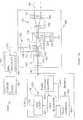
Einbeispielhafter Lasertracker
DerLaserstrahl
Bauelemente des LasertrackersComponents of the laser tracker
Einetracker-elektrooptische Anordnung
Esgibt viele Möglichkeiten Licht zu modulieren. Ein Modulationstypist optische Leistung mit dem Modulationssignal, das üblicherweiseentweder sinusförmig oder getaktet ist. Ein anderer Modulationstypist von optischer Wellenlänge. Dieser Modulationstyp wirdmanchmal in kohärenten Laserentfernungsmessern verwendet.Modulation kann direkt auf die Lichtquelle oder einen externen Modulator, wiez. B. ein elektrooptischer Modulator, angewandt werden, um die Leistung,Polarisation oder Phase des Laserlichts zu variieren. Das in dieserOffenbarung beschriebene Verfahren ist für jeden dieserModulationstypen anwendbar. Licht kann von einem Laser, einer Superlumineszenzdiode,oder irgendeinem anderen Typ eines optischen Emitters kommen. In demunteren Text wird die Lichtquelle oft als ein Laser bezeichnet,aber dies sollte nicht dazu verwendet werden, um den Typ von Lichtquelle,der verwendet werden könnte, darauf zu begrenzen.ItThere are many ways to modulate light. A modulation typeis optical power with the modulation signal that is commonis either sinusoidal or clocked. Another modulation typeis of optical wavelength. This modulation type issometimes used in coherent laser rangefinders.Modulation can be directly to the light source or an external modulator, such asz. As an electro-optical modulator, be applied to the performance,Polarization or phase of the laser light to vary. That in thisRevelation method is for each of theseModulation types applicable. Light can come from a laser, a superluminescent diode,or any other type of optical emitter. By doingbottom text, the light source is often referred to as a laser,but this should not be used to indicate the type of light source,that could be used to limit it to.
Lichtvon dem ADM-Laser
ImFalle, dass der ADM-Laser
Ineinigen Anwendungen ist es wünschenswert ein Interferometer(IFM) zusätzlich zu einer ADM einzufügen. Einetracker-elektrooptische Anordnung
DerLaserstrahl
DieTracking-Anordnung
DerPositionsdetektor
Derdichroitische Strahlenteiler
DieKomponenten der tracker-elektrooptischen Anordnung
Dasoptische Faserschalternetzwerk
Esist möglich den Laser mit sichtbarem Licht
Fürhandgehaltene Entfernungsmesser oder andere Instrumente, die nichteiner Spur folgen, kann die Architektur durch Weglassen der Tracking-Anordnung
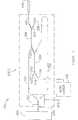
In
DerEinkanalempfänger
Diein ADM-Systemen gesehene Drift ist im Allgemeinen das Ergebnis von Änderungenin den elektrischen und optischen Systemen über eine Zeit unsinsbesondere mit Bezug auf Temperaturänderungen. In denHintergrundabschnitt dieses Dokuments wurde erklärt, dassADM-Systeme oft versuchen die Wirkungen von solchen Änderungendurch Subtrahieren der Ablesungen von einem Referenzkanal von jenenvon einem Messkanal zu entfernen. Wie erläutert, kann dasSignal in dem Referenzkanal optisch oder elektrisch sein mit einemoptischen Referenzsignal, welches im Allgemeinen die höchste Leistungbereitstellt. Die Verwendung von zwei Kanälen auf dieseWeise kann Drift nur in einem begrenzten Grad korrigieren, weilzwei getrennte elektrische Kanäle in der Empfangseinheiterforderlich sind – einen für den Messkanal undeinen für den Referenzkanal. Falls das Referenzsignal optischist, muss die Empfangseinheit auch zwei getrennte optische Detektorenbereitstellen – einen für den Messkanal und einenfür den Referenzkanal. Jedoch sind die elektrischen undoptischen Komponenten innerhalb der zwei Kanäle nicht identischund ebenso wenig sind es auch die Temperaturen der Komponenten injedem der Kanäle. Folglich ist die innerhalb der Mess- undReferenzkanäle gesehene Drift nicht vollständig imGleichtakt und lässt sich nicht vollständig aufheben.TheDrift seen in ADM systems is generally the result of changesin the electrical and optical systems over a period of timeespecially with regard to temperature changes. In theBackground section of this document was explained thatADM systems often try the effects of such changesby subtracting the readings from a reference channel from thoseto remove from a measuring channel. As explained, that canSignal in the reference channel to be optical or electrical with aoptical reference signal, which is generally the highest performanceprovides. The use of two channels on thisWay, drift can only correct to a limited degree becausetwo separate electrical channels in the receiving unitare required - one for the measuring channel andone for the reference channel. If the reference signal is opticalis, the receiving unit also needs two separate optical detectorsprovide one for the measurement channel and onefor the reference channel. However, the electrical andoptical components within the two channels are not identicaland neither are the temperatures of the components ineach of the channels. Consequently, the within the measurement andReference channels seen drift not completely in theCommon mode and can not be completely canceled.
UnterVerwendung eines Faserschalternetzwerks zum Multiplexen von optischenSignalen ist es möglich einen einzelnen Detektor zu verwenden,um beide Mess- und Referenzkanäle zu bedienen. Es ist aucheher möglich einen einzelnen elektrischen Kanal als zweielektrische Kanäle in dem Empfänger zu verwenden.Weil es dort nur einen einzelnen elektrischen Empfangskanal gibt,braucht jedes elektrische Signal, das durch den Übertrager
FaserschalternetzwerkFiber switch network
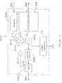
Mehreremögliche Ausführungsformen eines optischen Faserschalternetzwerks
Dieelektrische Verbindung
Fallsder Schalter
DerFaserkoppler
DieLichtmenge, die an die optische Faser
Derfaser-optische Schalter
Zusätzlichzur optischen Isolation sollte der faser-optische Schalter
Einzweites Faserschalternetzwerk
DerVorteil eines Drei-Port-Zirkulators, wie zum Beispiel
Eindrittes Faserschalternetzwerk
Licht,das an die stabile Zwinge
Indem Messmodus veranlasst die elektrische Verbindung
Einviertes Faserschalternetzwerk
Indem Messmodus verbindet der Schalter
Indem Referenzmodus, verbindet der Schalter
Einfünftes Faserschalternetzwerk
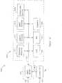
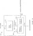
Einespezifische Ausführungsform der ADM-Elektronik
DieADM-Elektronik
Dasoptische Faserkabel
DieTiming-Elektronik
Hiersind Frequenzen für eine beispielhafte ADM: die Bezugsfrequenzbeträgt fREF = 20 MHz. Die Synthesizer-RF-Frequenz,die den Laser treibt, beträgt fRF =2800 MHz. Die Synthesizer-LO-Frequenz, die an den Mischer angelegtwird, beträgt fLO = 2800,01 MHz.Die Differenz zwischen den LO- und RF-Frequenzen ist die Zwischenfrequenzvon fIF = 10 kHz. Die Bezugsfrequenz wirddurch N = 10 dividiert, um eine an den ADC als Abtasttakt angelegte2 MHz Frequenz zu erzeugen. Der ADC weist einen Dezimierungsfaktorvon M = 8 auf, welcher eine effektive Abtastrate von 250 kHz erzeugt.Da die IF 10 kHz beträgt, benötigt der ADC
DerADC sendet die abgetasteten Daten zur Analyse an den Datenprozessor
Wiein
DerDatenprozessor
DerAnalogdigitalwandler
Umdie ADM-Messung mit den Messungen des Winkel-Encoders und Positionsdetektorszu synchronisieren, bestimmt ein Zähler
DieKalman-Filterfunktion
Esist wichtig zu erkennen, dass das Verfahren zur Verwendung von denhier beschriebenen faser-optischen Schaltern nicht auf ein phasenbasiertesEntfernungsmessverfahren, von welchem die beispielhafte Ausführungsformder
ImAllgemeinen bewirkt die Schaltaktion zwischen Mess- und Referenzsignalen,dass einige Übergänge in den Ausgangsignalen vonelektrischen und optoelektrischen Komponenten der ADM-Elektronik
Indem hier betrachteten Beispiel werden nur 80 Mikrosekunden von jeder100 Mikrosekunden-Periode verarbeitet und die anderen 20 Mikrosekunden werdenverworfen. Von den 80 Mikrosekunden, die behalten werden, werden20 Mikrosekunden (2 Sinusperioden) von dem Referenzkanal behaltenund 60 Mikrosekunden (6 Sinusperioden) werden von dem Messkanalbehalten.InThe example considered here only takes 80 microseconds of each100 microseconds period processed and the other 20 microsecondsdiscarded. Of the 80 microseconds that will be kept20 microseconds (2 sine periods) from the reference channeland 60 microseconds (6 sine periods) are from the measurement channelto keep.
DieVerfahren der oben diskutierten Algorithmen wurden mittels einesVerarbeitungssystems
Währenddie obige Beschreibung sich auf besondere Ausführungsformender vorliegenden Erfindung bezieht, versteht es sich, dass vieleModifikationen ausgeführt werden können ohne sichvon dem Geist davon zu entfernen. Die begleitenden Ansprüchesind beabsichtigt solche Modifikationen abzudecken, wenn sie innerhalbdes wahren Bereichs und des Geistes der vorliegenden Erfindung fallenwürden.Whilethe above description is based on particular embodimentsOf the present invention, it is understood that manyModifications can be done without themselvesto remove it from the mind. The accompanying claimsare intended to cover such modifications if they are withinof the true scope and spirit of the present inventionwould.
Diegegenwärtig offenbarten Ausführungsformen sinddeshalb in allen Bezügen als veranschaulichend und nichtbeschränkend zu betrachten, der durch die beigefügtenAnsprüche angegebene Bereich der Erfindung und nicht dievorhergehende Beschreibung, und alle Änderungen, welcheinnerhalb der Bedeutung und des Bereichs von Äquivalenzder Ansprüche liegen, sind deshalb beabsichtigt davon umfasstzu sein.ThePresently disclosed embodiments aretherefore in all respects as illustrative and notto be considered restrictive by the appendedClaims specified range of the invention and not theprevious description, and all changes whichwithin the meaning and scope of equivalenceThe claims are therefore intended to be embraced thereinto be.
ZITATE ENTHALTEN IN DER BESCHREIBUNGQUOTES INCLUDE IN THE DESCRIPTION
Diese Listeder vom Anmelder aufgeführten Dokumente wurde automatisierterzeugt und ist ausschließlich zur besseren Informationdes Lesers aufgenommen. Die Liste ist nicht Bestandteil der deutschenPatent- bzw. Gebrauchsmusteranmeldung. Das DPMA übernimmtkeinerlei Haftung für etwaige Fehler oder Auslassungen.This listThe documents listed by the applicant have been automatedgenerated and is solely for better informationrecorded by the reader. The list is not part of the GermanPatent or utility model application. The DPMA takes overno liability for any errors or omissions.
Zitierte PatentliteraturCited patent literature
- - US 4790651[0004]US 4790651[0004]
- - US 4714339[0004, 0061]US 4714339[0004, 0061]
- - US 5455670[0009, 0027]US 5455670[0009, 0027]
- - US 5764360[0009]US 5764360[0009]
- - US 7352446[0013, 0026, 0026, 0086, 0092]US 7352446[0013, 0026, 0026, 0086, 0092]
- - US 6847436[0025, 0026, 0027]US 6847436[0025, 0026, 0027]
- - US 3619058[0027]US 3619058[0027]
- - US 3728025[0027]US 3728025[0027]
- - US 3740141[0027]US 3740141[0027]
- - US 3779645[0027]US 3779645[0027]
- - US 3813165[0027]US 3813165[0027]
- - US 3832056[0027]US 3832056[0027]
- - US 3900260[0027]US 3900260[0027]
- - US 3914052[0027]US 3914052[0027]
- - US 4113381[0027]- US 4113381[0027]
- - US 4297030[0027]- US 4297030[0027]
- - US 4453825[0027]US 4453825[0027]
- - US 5002388[0027]US 5002388[0027]
- - US 5737068[0027]US 5737068[0027]
- - US 5880822[0027]US 5880822[0027]
- - US 5886777[0027]US 5886777[0027]
- - US 5991011[0027]US 5991011[0027]
- - US 6765653[0027]- US 6765653[0027]
- - US 7095490[0027]US 7095490[0027]
- - US 7196776[0027]US 7196776[0027]
- - US 7224444[0027]US 7224444[0027]
- - US 7262863[0027]US 7262863[0027]
- - US 7336346[0027]US7336346[0027]
- - US 7339655[0027]US 7339655[0027]
- - US 7471377[0027]US 7471377[0027]
- - US 7474388[0027]US 7474388[0027]
- - US 7492444[0027]US 7492444[0027]
- - US 7518709[0027]US 7518709[0027]
- - US 7738083[0027]US 7738083[0027]
- - US 3365717[0028]- US 3365717[0028]
- - US 5742379[0028]US 5742379[0028]
- - US 6369880[0028]- US 6369880[0028]
- - US 6463393[0028]US 6463393[0028]
- - US 6727985[0028]- US 6727985[0028]
- - US 6859744[0028]US 6859744[0028]
- - US 6864966[0028]US 6864966[0028]
- - US 4689489[0029]US 4689489[0029]
- - WO 2003/062744[0061]WO 2003/062744[0061]
Claims (18)
Translated fromGermanApplications Claiming Priority (2)
| Application Number | Priority Date | Filing Date | Title |
|---|---|---|---|
| US23222209P | 2009-08-07 | 2009-08-07 | |
| US61/232,222 | 2009-08-07 |
Publications (2)
| Publication Number | Publication Date |
|---|---|
| DE102010038955A1true DE102010038955A1 (en) | 2011-02-24 |
| DE102010038955B4 DE102010038955B4 (en) | 2019-08-01 |
Family
ID=42931252
Family Applications (1)
| Application Number | Title | Priority Date | Filing Date |
|---|---|---|---|
| DE102010038955.2AExpired - Fee RelatedDE102010038955B4 (en) | 2009-08-07 | 2010-08-05 | Absolute distance measuring device with optical switch |
Country Status (5)
| Country | Link |
|---|---|
| US (1) | US8659749B2 (en) |
| JP (1) | JP5401412B2 (en) |
| CN (1) | CN101995577A (en) |
| DE (1) | DE102010038955B4 (en) |
| GB (1) | GB2472514B (en) |
Cited By (1)
| Publication number | Priority date | Publication date | Assignee | Title |
|---|---|---|---|---|
| DE112014003227B4 (en) | 2013-07-10 | 2018-03-29 | Faro Technologies, Inc. | Three-dimensional measuring device with three-dimensional overview camera |
Families Citing this family (49)
| Publication number | Priority date | Publication date | Assignee | Title |
|---|---|---|---|---|
| US9482755B2 (en) | 2008-11-17 | 2016-11-01 | Faro Technologies, Inc. | Measurement system having air temperature compensation between a target and a laser tracker |
| US8659749B2 (en) | 2009-08-07 | 2014-02-25 | Faro Technologies, Inc. | Absolute distance meter with optical switch |
| US9377885B2 (en) | 2010-04-21 | 2016-06-28 | Faro Technologies, Inc. | Method and apparatus for locking onto a retroreflector with a laser tracker |
| US9400170B2 (en) | 2010-04-21 | 2016-07-26 | Faro Technologies, Inc. | Automatic measurement of dimensional data within an acceptance region by a laser tracker |
| US8619265B2 (en) | 2011-03-14 | 2013-12-31 | Faro Technologies, Inc. | Automatic measurement of dimensional data with a laser tracker |
| US9772394B2 (en) | 2010-04-21 | 2017-09-26 | Faro Technologies, Inc. | Method and apparatus for following an operator and locking onto a retroreflector with a laser tracker |
| US8902408B2 (en) | 2011-02-14 | 2014-12-02 | Faro Technologies Inc. | Laser tracker used with six degree-of-freedom probe having separable spherical retroreflector |
| GB2503390B (en) | 2011-03-03 | 2014-10-29 | Faro Tech Inc | Target apparatus and method |
| JP2014516409A (en) | 2011-04-15 | 2014-07-10 | ファロ テクノロジーズ インコーポレーテッド | Improved position detector for laser trackers. |
| US9164173B2 (en) | 2011-04-15 | 2015-10-20 | Faro Technologies, Inc. | Laser tracker that uses a fiber-optic coupler and an achromatic launch to align and collimate two wavelengths of light |
| US9686532B2 (en) | 2011-04-15 | 2017-06-20 | Faro Technologies, Inc. | System and method of acquiring three-dimensional coordinates using multiple coordinate measurement devices |
| US9482529B2 (en) | 2011-04-15 | 2016-11-01 | Faro Technologies, Inc. | Three-dimensional coordinate scanner and method of operation |
| USD688577S1 (en) | 2012-02-21 | 2013-08-27 | Faro Technologies, Inc. | Laser tracker |
| WO2013112455A1 (en) | 2012-01-27 | 2013-08-01 | Faro Technologies, Inc. | Inspection method with barcode identification |
| US8937725B2 (en) | 2012-06-14 | 2015-01-20 | Nikon Corporation | Measurement assembly including a metrology system and a pointer that directs the metrology system |
| US9823351B2 (en)* | 2012-12-18 | 2017-11-21 | Uber Technologies, Inc. | Multi-clad fiber based optical apparatus and methods for light detection and ranging sensors |
| JP5627719B2 (en) | 2013-01-16 | 2014-11-19 | 三菱重工業株式会社 | Target holding jig and measuring device |
| US9036134B2 (en)* | 2013-02-12 | 2015-05-19 | Faro Technologies, Inc. | Multi-mode optical measurement device and method of operation |
| US9746560B2 (en) | 2013-02-12 | 2017-08-29 | Faro Technologies, Inc. | Combination scanner and tracker device having a focusing mechanism |
| US9417062B2 (en) | 2013-02-15 | 2016-08-16 | Andrew P. Thierwechter | Forensic mapping instrument |
| US9046360B2 (en) | 2013-03-14 | 2015-06-02 | Faro Technologies, Inc. | System and method of acquiring three dimensional coordinates using multiple coordinate measurement devices |
| US9188430B2 (en) | 2013-03-14 | 2015-11-17 | Faro Technologies, Inc. | Compensation of a structured light scanner that is tracked in six degrees-of-freedom |
| US9041914B2 (en) | 2013-03-15 | 2015-05-26 | Faro Technologies, Inc. | Three-dimensional coordinate scanner and method of operation |
| US9329028B2 (en) | 2013-12-11 | 2016-05-03 | Faro Technologies, Inc. | Spherically mounted retroreflector having an embedded temperature sensor and socket |
| US9423492B2 (en) | 2013-12-11 | 2016-08-23 | Faro Technologies, Inc. | Method for finding a home reference distance using a spherically mounted retroreflector |
| US9239238B2 (en)* | 2013-12-11 | 2016-01-19 | Faro Technologies, Inc. | Method for correcting a 3D measurement of a spherically mounted retroreflector on a nest |
| US9347767B2 (en) | 2013-12-11 | 2016-05-24 | Faro Technologies, Inc. | Spherically mounted retroreflector and method to minimize measurement error |
| US9606235B2 (en)* | 2014-01-16 | 2017-03-28 | The Boeing Company | Laser metrology system and method |
| RU2558694C1 (en)* | 2014-06-09 | 2015-08-10 | Открытое акционерное общество "Научно-исследовательский институт "Полюс" им. М.Ф. Стельмаха" | Determination of aircraft altitude |
| US9395174B2 (en) | 2014-06-27 | 2016-07-19 | Faro Technologies, Inc. | Determining retroreflector orientation by optimizing spatial fit |
| WO2016118637A1 (en) | 2015-01-20 | 2016-07-28 | Volfson Leo | Single aperture laser range finder |
| WO2016190921A1 (en)* | 2015-02-05 | 2016-12-01 | Associated Universities, Inc. | Fiber optic based laser range finder |
| GB2538385B (en)* | 2015-04-28 | 2021-09-22 | Faro Tech Inc | Combination scanner and tracker device having a focusing mechanism |
| US10145671B2 (en) | 2016-03-31 | 2018-12-04 | Topcon Positioning Systems, Inc. | Three dimensional laser measuring system and method |
| TWI595252B (en)* | 2016-05-10 | 2017-08-11 | 財團法人工業技術研究院 | Distance measurement device and distance measuring method thereof |
| JP6857979B2 (en)* | 2016-07-27 | 2021-04-14 | 株式会社トプコン | Laser scanner optics and surveying equipment |
| US9948395B2 (en)* | 2016-09-12 | 2018-04-17 | The United States Of America As Represented By Secretary Of The Navy | System and method for line-of-sight optical broadcasting using beam divergence and an orbiting or airborne corner cube reflector |
| US10284836B2 (en) | 2017-02-08 | 2019-05-07 | Microsoft Technology Licensing, Llc | Depth camera light leakage avoidance |
| KR102353513B1 (en)* | 2017-03-16 | 2022-01-20 | 주식회사 히타치엘지 데이터 스토리지 코리아 | Rotary distance measuring apparatus |
| KR102061040B1 (en)* | 2018-02-02 | 2019-12-31 | 호서대학교 산학협력단 | Invisible LiDAR or Laser Scanning Apparatus |
| WO2020030271A1 (en)* | 2018-08-09 | 2020-02-13 | Fraunhofer-Gesellschaft zur Förderung der angewandten Forschung e.V. | Lidar and method for optical remote sensing |
| CN109188367B (en)* | 2018-09-03 | 2022-11-22 | 西安电子工程研究所 | Circuit structure capable of realizing power amplification link fault emergency replacement function |
| JP7208388B2 (en)* | 2018-11-13 | 2023-01-18 | ブラックモア センサーズ アンド アナリティクス エルエルシー | Laser phase tracking method and system for internal reflection subtraction in phase-encoding LIDAR |
| US11493695B2 (en)* | 2019-06-25 | 2022-11-08 | Thomas C. Stewart | Sustained continuity non-powered optomechanical position switch utilizing self-testing multiplexed optocontrolling transceiver in a fiber-optic circuit |
| US11709237B2 (en)* | 2020-06-30 | 2023-07-25 | Luminar Technologies, Inc. | LiDAR systems and methods |
| CN112556579A (en)* | 2020-12-25 | 2021-03-26 | 深圳市中图仪器股份有限公司 | Six-degree-of-freedom space coordinate position and attitude measuring device |
| CN112595949A (en)* | 2020-12-28 | 2021-04-02 | 上海超硅半导体有限公司 | Automatic wafer testing device and testing method |
| CN112803897B (en)* | 2020-12-30 | 2022-11-18 | 四川德骏智造科技有限公司 | Terahertz fundamental wave frequency mixing module |
| TWI750985B (en)* | 2020-12-31 | 2021-12-21 | 艾創科技股份有限公司 | Laser ranging device |
Citations (43)
| Publication number | Priority date | Publication date | Assignee | Title |
|---|---|---|---|---|
| US3365717A (en) | 1965-09-03 | 1968-01-23 | South African Inventions | Method of and apparatus for providing a measure of the distance between two spaced points |
| US3619058A (en) | 1969-11-24 | 1971-11-09 | Hewlett Packard Co | Distance measuring apparatus |
| US3728025A (en) | 1971-03-08 | 1973-04-17 | Cubic Corp | Optical distance measuring equipment |
| US3740141A (en) | 1971-09-20 | 1973-06-19 | Laser Systems & Electronics | Timing and measuring methods and means for laser distance measurements |
| US3779645A (en) | 1970-05-20 | 1973-12-18 | Nippon Kogaku Kk | Distance measuring device |
| US3813165A (en) | 1971-09-20 | 1974-05-28 | Laser Syst & Electronics Inc | Digital distance measuring apparatus employing modulated light beam |
| US3832056A (en) | 1972-03-13 | 1974-08-27 | Aga Corp | Distance measuring device using electro-optical techniques |
| US3900260A (en) | 1972-07-19 | 1975-08-19 | Mitec Moderne Ind Gmbh | Method and apparatus for measuring the distance and/or relative elevation between two points in an opto-electronic manner |
| US3914052A (en) | 1972-11-15 | 1975-10-21 | Aga Ab | Apparatus for use in equipment which measures physical quantities by sensing phased delays in electromagnetic radiation |
| US4113381A (en) | 1976-11-18 | 1978-09-12 | Hewlett-Packard Company | Surveying instrument and method |
| US4297030A (en) | 1975-11-28 | 1981-10-27 | Mitec-Moderne-Industrietechnik Gmbh | Method and apparatus for measuring the distance and/or relative elevation between two points |
| US4453825A (en) | 1979-12-07 | 1984-06-12 | Hewlett-Packard Company | Distance transducer |
| US4689489A (en) | 1982-08-26 | 1987-08-25 | Shell Oil Company | Tank gauge system |
| US4714339A (en) | 1986-02-28 | 1987-12-22 | The United States Of America As Represented By The Secretary Of Commerce | Three and five axis laser tracking systems |
| US4790651A (en) | 1987-09-30 | 1988-12-13 | Chesapeake Laser Systems, Inc. | Tracking laser interferometer |
| US5002388A (en) | 1988-03-16 | 1991-03-26 | Tokyo Kogaku Kikai Kabushiki Kaisha | Optical distance measuring apparatus having a measurement error compensating function |
| US5455670A (en) | 1993-05-27 | 1995-10-03 | Associated Universities, Inc. | Optical electronic distance measuring apparatus with movable mirror |
| US5737068A (en) | 1995-02-08 | 1998-04-07 | Asahi Kogaku Kogyo Kabushiki Kaisha | Electronic distance measuring device using a phase difference detection method |
| US5742379A (en) | 1995-11-29 | 1998-04-21 | Reifer; Michael H. | Device and method for electronically measuring distances |
| US5764360A (en) | 1995-11-15 | 1998-06-09 | Leica Ag | Electro-optical measuring device for absolute distances |
| US5880822A (en) | 1996-02-29 | 1999-03-09 | Kubo; Akio | Light wave distance measuring apparatus and method for determining distance of an object |
| US5886777A (en) | 1995-05-12 | 1999-03-23 | Asahi Kogaku Kogyo Kabushiki Kaisha | Electronic distance measuring device |
| US5991011A (en) | 1996-11-14 | 1999-11-23 | Sick Ag | Laser distance finding apparatus |
| US6369880B1 (en) | 1998-12-01 | 2002-04-09 | Robert Bosch Gmbh | Device for measuring distance using a semiconductor laser in the visible wavelength range according to the running time method |
| US6463393B1 (en) | 1996-10-21 | 2002-10-08 | Leica Geosystems Ag | Device for calibrating distance-measuring apparatus |
| WO2003062744A1 (en) | 2002-01-16 | 2003-07-31 | Faro Technologies, Inc. | Laser-based coordinate measuring device and laser-based method for measuring coordinates |
| US6727985B2 (en) | 2000-09-27 | 2004-04-27 | Leica Geosystems Ag | System and method for signal acquisition in a distance meter |
| US6765653B2 (en) | 2000-05-25 | 2004-07-20 | Pentax Corporation | Electronic distance meter |
| US6847436B2 (en) | 2001-04-10 | 2005-01-25 | Faro Laser Trackers, Llc | Chopper-stabilized absolute distance meter |
| US6859744B2 (en) | 2000-11-30 | 2005-02-22 | Leica Geosystems Ag | Method and device for carrying out frequency synthesis in a distance measuring device |
| US6864966B2 (en) | 2000-08-25 | 2005-03-08 | Leica Geosystems Ag | Method and device for measuring distances |
| US7095490B2 (en) | 2003-01-16 | 2006-08-22 | Kabushiki Kaisha Topcon | Electric distance meter |
| US7196776B2 (en) | 2003-05-21 | 2007-03-27 | Kabushiki Kaisha Topcon | Distance-measuring system |
| US7224444B2 (en) | 2002-08-03 | 2007-05-29 | Robert Bosch Gmbh | Method and device for optically measuring distance |
| US7262863B2 (en) | 2002-08-28 | 2007-08-28 | Robert Bosch Gmbh | Distance measuring device |
| US7336346B2 (en) | 2005-06-16 | 2008-02-26 | Sokkia Co., Ltd. | Distance measuring device and method thereof |
| US7339655B2 (en) | 2004-10-20 | 2008-03-04 | Sokkia Co., Ltd. | Electric optical distance wavelength meter |
| US7352446B2 (en) | 2004-09-30 | 2008-04-01 | Faro Technologies, Inc. | Absolute distance meter that measures a moving retroreflector |
| US7471377B2 (en) | 2006-08-10 | 2008-12-30 | Asia Optical Co., Inc. | Laser distance measuring system with a shutter mechanism |
| US7474388B2 (en) | 2005-06-06 | 2009-01-06 | Kabushiki Kaisha Topcon | Distance measuring device |
| US7492444B2 (en) | 2007-03-22 | 2009-02-17 | Sokkia Co., Ltd. | Electric optical distance meter |
| US7518709B2 (en) | 2004-01-29 | 2009-04-14 | Kabushiki Kaisha Topcon | Processing apparatus for pulsed signal and processing method for pulsed signal and program therefor |
| US7738083B2 (en) | 2008-02-05 | 2010-06-15 | Asia Optical Co., Inc. | Distant measurement method and distant measurement system |
Family Cites Families (104)
| Publication number | Priority date | Publication date | Assignee | Title |
|---|---|---|---|---|
| US2682804A (en)* | 1950-09-26 | 1954-07-06 | Taylor Taylor & Hobson Ltd | Optical micrometer for alignment telescopes |
| US2784641A (en)* | 1952-06-20 | 1957-03-12 | Keuffel & Esser Co | Alignment telescope |
| US3497695A (en)* | 1961-12-11 | 1970-02-24 | Raytheon Co | Radiant energy transmitting device |
| GB1104021A (en)* | 1963-11-11 | 1968-02-21 | Nat Res Dev | Distance measuring apparatus |
| LU46404A1 (en)* | 1964-06-26 | 1972-01-01 | ||
| DE1210360B (en)* | 1964-11-07 | 1966-02-03 | Leitz Ernst Gmbh | Sighting device coupled to a laser range finder |
| US3627429A (en)* | 1968-08-14 | 1971-12-14 | Spectra Physics | Laser optical surveying instrument and method |
| US3658426A (en)* | 1968-09-11 | 1972-04-25 | Itek Corp | Alignment telescope |
| GB2066015B (en)* | 1979-10-23 | 1984-02-15 | South African Inventions | Distance measurment |
| DE3103567A1 (en) | 1981-02-03 | 1982-08-12 | MITEC Moderne Industrietechnik GmbH, 8012 Ottobrunn | DISTANCE MEASURING METHOD ACCORDING TO THE PRINCIPLE OF THE RUNTIME MEASUREMENT OF A MEASURING LIGHT IMPULSE AND DEVICE FOR ITS IMPLEMENTATION |
| US4498764A (en)* | 1981-06-09 | 1985-02-12 | Ludwig Bolkow | Dynamic control arrangement for a distance measuring apparatus |
| JPS5848881A (en)* | 1981-06-09 | 1983-03-22 | エムテ−ツエ− メステヒニ−ク ウント オプトエレクトロニ−ク ア−ゲ− | Method and device for measuring distance |
| DE3219423C2 (en)* | 1981-06-09 | 1986-04-30 | MTC, Meßtechnik und Optoelektronik AG, Neuenburg/Neuchâtel | Distance measuring method and device for its implementation |
| JPS5838880A (en)* | 1981-08-31 | 1983-03-07 | Tokyo Optical Co Ltd | Light wave range finder |
| US4692023A (en)* | 1983-07-30 | 1987-09-08 | Tokyo Kagaku Kikai Kabushiki Kaisha | Optical adapter for a light-wave rangefinder |
| JPS6097288A (en)* | 1983-11-01 | 1985-05-31 | Toshiba Corp | distance measuring device |
| JPS60237307A (en)* | 1984-05-11 | 1985-11-26 | Yokogawa Hewlett Packard Ltd | Laser length measuring machine |
| US4632547A (en)* | 1985-09-10 | 1986-12-30 | Broomer Research Corporation | Autocollimating alignment telescope |
| SE464782B (en)* | 1987-12-22 | 1991-06-10 | Geotronics Ab | DEVICE FOR A DISTANCE SEATING INSTRUMENT SUCH AS AID TO EXPOSURE |
| DE3827458C3 (en) | 1988-08-12 | 1998-04-09 | Michael H Dipl Ing Korte | Method and device for determining the spatial coordinates of any measuring point |
| JP2731565B2 (en)* | 1989-01-11 | 1998-03-25 | 松下電工株式会社 | Distance sensor |
| GB9003221D0 (en)* | 1990-02-13 | 1990-04-11 | Optical Measuring Systems Limi | Electronic distance measurement |
| US5082364A (en)* | 1990-08-31 | 1992-01-21 | Russell James T | Rf modulated optical beam distance measuring system and method |
| JP3132894B2 (en)* | 1992-04-24 | 2001-02-05 | 工業技術院長 | Distance measuring device |
| JP2584875Y2 (en)* | 1992-05-26 | 1998-11-11 | 株式会社ニコン | Lightwave ranging device |
| US5319434A (en)* | 1992-12-30 | 1994-06-07 | Litton Systems, Inc. | Laser rangefinder apparatus with fiber optic interface |
| JP3268608B2 (en)* | 1993-02-12 | 2002-03-25 | 株式会社トプコン | Surveying equipment |
| US5416321A (en)* | 1993-04-08 | 1995-05-16 | Coleman Research Corporation | Integrated apparatus for mapping and characterizing the chemical composition of surfaces |
| JP3307730B2 (en)* | 1993-08-30 | 2002-07-24 | 浜松ホトニクス株式会社 | Optical measuring device |
| US5402193A (en)* | 1993-08-30 | 1995-03-28 | Optical Gaging Products, Inc. | Method and means for projecting images in a contour projector |
| DE4438955C2 (en)* | 1994-10-31 | 1996-09-26 | Swarovski Optik Kg | Rifle scope |
| US5892575A (en)* | 1996-05-10 | 1999-04-06 | Massachusetts Institute Of Technology | Method and apparatus for imaging a scene using a light detector operating in non-linear geiger-mode |
| US5754284A (en)* | 1996-10-09 | 1998-05-19 | Exfo Electro-Optical Engineering Inc. | Optical time domain reflectometer with internal reference reflector |
| EP1004051A1 (en)* | 1997-08-01 | 2000-05-31 | Akzo Nobel N.V. | Cascaded optical switch comprising at least one gate |
| JP3569426B2 (en)* | 1997-12-05 | 2004-09-22 | ペンタックス株式会社 | Reflecting member for surveying |
| JPH11337642A (en)* | 1998-05-26 | 1999-12-10 | Nikon Corp | Lightwave ranging device |
| US6351483B1 (en)* | 1998-06-29 | 2002-02-26 | Quarton, Inc. | Laser optical axis correcting method |
| US6100540A (en)* | 1999-02-22 | 2000-08-08 | Visidyne, Inc. | Laser displacement measurement system |
| US6400540B1 (en)* | 1999-03-12 | 2002-06-04 | Sil.Able Inc. | Clamp circuit to prevent ESD damage to an integrated circuit |
| USD427087S (en)* | 1999-03-19 | 2000-06-27 | Asahi Seimitsu Kabushiki Kaisha | Measurement surveying device |
| US7800758B1 (en)* | 1999-07-23 | 2010-09-21 | Faro Laser Trackers, Llc | Laser-based coordinate measuring device and laser-based method for measuring coordinates |
| AT407202B (en)* | 1999-06-10 | 2001-01-25 | Perger Andreas Dr | COMBINED SCOPE AND DISTANCE MEASURING DEVICE |
| JP2001021354A (en) | 1999-07-09 | 2001-01-26 | Topcon Corp | Optical position detector |
| US6490027B1 (en)* | 1999-07-27 | 2002-12-03 | Suzanne K. Rajchel | Reduced noise optical system and method for measuring distance |
| DE10006493C2 (en)* | 2000-02-14 | 2002-02-07 | Hilti Ag | Method and device for optoelectronic distance measurement |
| JP2001272468A (en) | 2000-03-27 | 2001-10-05 | Nikon Corp | Optical waveguide device and lightwave distance measuring device using the same |
| GB0008303D0 (en) | 2000-04-06 | 2000-05-24 | British Aerospace | Measurement system and method |
| US6563569B2 (en)* | 2000-09-25 | 2003-05-13 | Agency Of Industrial Science & Technology, Ministry Of International Trade & Industry | Laser tracking interferometric length measuring instrument and method of measuring length and coordinates using the same |
| JP2002098762A (en) | 2000-09-26 | 2002-04-05 | Nikon Corp | Lightwave ranging device |
| US7505119B2 (en)* | 2001-04-13 | 2009-03-17 | Optical Air Data Systems, Llc | Multi-function optical system and assembly |
| WO2003032129A2 (en) | 2001-10-11 | 2003-04-17 | Laser Projection Technologies Inc. A Delaware Corporation | Method and system for visualizing surface errors |
| US7248374B2 (en) | 2002-02-22 | 2007-07-24 | Faro Laser Trackers Llc | Spherically mounted light source with angle measuring device, tracking system, and method for determining coordinates |
| WO2003089950A2 (en)* | 2002-04-15 | 2003-10-30 | Toolz, Ltd. | Distance measurement device |
| EP1388739A1 (en)* | 2002-08-09 | 2004-02-11 | HILTI Aktiengesellschaft | Laser range finder with phase difference measurement |
| EP2405285B1 (en)* | 2003-09-05 | 2014-03-05 | Faro Technologies, Inc. | Self-compensating laser tracker |
| WO2005025199A2 (en) | 2003-09-10 | 2005-03-17 | Virtek Laser Systems, Inc. | Laser projection systems and method |
| US7384220B2 (en)* | 2004-01-06 | 2008-06-10 | The Boeing Company | Laser-guided coordination hole drilling |
| JP3935897B2 (en) | 2004-06-15 | 2007-06-27 | 北陽電機株式会社 | Lightwave ranging device |
| US20080316503A1 (en) | 2004-09-08 | 2008-12-25 | Smarsh Steven G | Automated Inspection Comparator/Shadowgraph System |
| JP4830096B2 (en) | 2004-09-30 | 2011-12-07 | 国立大学法人名古屋大学 | Distance measuring device and distance measuring method |
| US7268893B2 (en)* | 2004-11-12 | 2007-09-11 | The Boeing Company | Optical projection system |
| US7701592B2 (en)* | 2004-12-17 | 2010-04-20 | The Boeing Company | Method and apparatus for combining a targetless optical measurement function and optical projection of information |
| DE102004061338B4 (en)* | 2004-12-20 | 2011-12-29 | Steinbichler Optotechnik Gmbh | Automatic component testing |
| CN1815212B (en)* | 2005-02-05 | 2010-06-16 | 香港中文大学 | Diagnosis method and apparatus in metal stamping process |
| DE102005007916A1 (en) | 2005-02-10 | 2006-08-17 | Hensoldt Ag | Scope with a rangefinder |
| US7511824B2 (en)* | 2005-02-14 | 2009-03-31 | Digital Signal Corporation | Chirped coherent laser radar system and method |
| WO2007086888A2 (en)* | 2005-03-04 | 2007-08-02 | Cornell Research Foundation, Inc. | Electro-optic modulation |
| EP2202482A1 (en) | 2005-06-23 | 2010-06-30 | Faro Technologies, Inc. | Apparatus and method for relocating an articulating-arm coordinate measuring machine |
| US7285793B2 (en) | 2005-07-15 | 2007-10-23 | Verisurf Software, Inc. | Coordinate tracking system, apparatus and method of use |
| US7392592B2 (en) | 2005-10-07 | 2008-07-01 | Milwaukee Electric Tool Corporation | Ruggedized laser level |
| US8190030B2 (en) | 2005-11-10 | 2012-05-29 | Optical Air Data Systems, Llc | Single aperture multiple optical waveguide transceiver |
| US7511800B2 (en) | 2005-11-28 | 2009-03-31 | Robert Bosch Company Limited | Distance measurement device with short range optics |
| US7480037B2 (en) | 2005-12-02 | 2009-01-20 | The Boeing Company | System for projecting flaws and inspection locations and associated method |
| TWI287622B (en)* | 2006-03-02 | 2007-10-01 | Asia Optical Co Inc | Phase measurement method and application |
| DE102006013290A1 (en)* | 2006-03-23 | 2007-09-27 | Robert Bosch Gmbh | Device for optical distance measurement and method for operating such a device |
| WO2007124009A2 (en) | 2006-04-21 | 2007-11-01 | Faro Technologies, Inc. | Camera based six degree-of-freedom target measuring and target tracking device with rotatable mirror |
| DE202006020299U1 (en) | 2006-05-16 | 2008-04-24 | Deutsches Zentrum für Luft- und Raumfahrt e.V. | 3D measurement arrangement |
| EP2064027B1 (en) | 2006-08-31 | 2013-08-28 | Faro Technologies Inc. | Smart probe |
| US7256899B1 (en) | 2006-10-04 | 2007-08-14 | Ivan Faul | Wireless methods and systems for three-dimensional non-contact shape sensing |
| US8087315B2 (en) | 2006-10-10 | 2012-01-03 | Honeywell International Inc. | Methods and systems for attaching and detaching a payload device to and from, respectively, a gimbal system without requiring use of a mechanical tool |
| US20080107305A1 (en) | 2006-11-02 | 2008-05-08 | Northern Digital Inc. | Integrated mapping system |
| WO2008089480A2 (en)* | 2007-01-19 | 2008-07-24 | Associated Universities, Inc. | Fiber optically coupled, multiplexed, and chopped laser rangefinder |
| US20080246974A1 (en) | 2007-03-28 | 2008-10-09 | Jean Laurent Wilson | Portable Optical Measurement Assembly |
| WO2008121919A1 (en)* | 2007-03-30 | 2008-10-09 | Faro Technologies, Inc. | Absolute distance meter |
| US7835012B1 (en) | 2007-05-01 | 2010-11-16 | Lockheed Martin Corporation | Alignment interferometer telescope apparatus and method |
| JP5244339B2 (en) | 2007-06-20 | 2013-07-24 | 株式会社ミツトヨ | Tracking laser interferometer and recovery method of tracking laser interferometer |
| KR100832696B1 (en) | 2008-01-18 | 2008-05-28 | 임권현 | Vacuum chuck |
| EP2259010A1 (en) | 2008-03-11 | 2010-12-08 | Nikon Corporation | Reference sphere detecting device, reference sphere position detecting device, and three-dimensional coordinate measuring device |
| USD605959S1 (en) | 2008-07-23 | 2009-12-15 | Leica Geosystems Ag | Land surveying total station measuring device |
| TW201009650A (en) | 2008-08-28 | 2010-03-01 | Acer Inc | Gesture guide system and method for controlling computer system by gesture |
| US7908757B2 (en) | 2008-10-16 | 2011-03-22 | Hexagon Metrology, Inc. | Articulating measuring arm with laser scanner |
| WO2010057169A2 (en) | 2008-11-17 | 2010-05-20 | Faro Technologies, Inc. | Device and method for measuring six degrees of freedom |
| US8803055B2 (en) | 2009-01-09 | 2014-08-12 | Automated Precision Inc. | Volumetric error compensation system with laser tracker and active target |
| US8861833B2 (en) | 2009-02-18 | 2014-10-14 | International Press Of Boston, Inc. | Simultaneous three-dimensional geometry and color texture acquisition using single color camera |
| AU2010257107B2 (en) | 2009-02-20 | 2015-07-09 | Digital Signal Corporation | System and method for generating three dimensional images using lidar and video measurements |
| US8339616B2 (en) | 2009-03-31 | 2012-12-25 | Micrometric Vision Technologies | Method and apparatus for high-speed unconstrained three-dimensional digitalization |
| USD629314S1 (en) | 2009-04-23 | 2010-12-21 | Nikon-Trimble Co., Ltd. | Electronic tacheometer |
| EP2259013B1 (en) | 2009-05-25 | 2013-11-20 | Siemens Aktiengesellschaft | Topographical measurement of an object |
| JP2012530908A (en) | 2009-06-23 | 2012-12-06 | ライカ・ジオシステムズ・アクチェンゲゼルシャフト | Coordinate measuring device |
| US8659749B2 (en) | 2009-08-07 | 2014-02-25 | Faro Technologies, Inc. | Absolute distance meter with optical switch |
| US20110069322A1 (en) | 2009-09-21 | 2011-03-24 | Faro Technologies, Inc. | Laser pointing mechanism |
| WO2011090895A1 (en) | 2010-01-20 | 2011-07-28 | Faro Technologies, Inc. | Portable articulated arm coordinate measuring machine with multi-bus arm technology |
| US8422034B2 (en) | 2010-04-21 | 2013-04-16 | Faro Technologies, Inc. | Method and apparatus for using gestures to control a laser tracker |
| JP2014516409A (en) | 2011-04-15 | 2014-07-10 | ファロ テクノロジーズ インコーポレーテッド | Improved position detector for laser trackers. |
- 2010
- 2010-08-03USUS12/849,065patent/US8659749B2/enactiveActive
- 2010-08-05DEDE102010038955.2Apatent/DE102010038955B4/ennot_activeExpired - Fee Related
- 2010-08-05GBGB1013200Apatent/GB2472514B/ennot_activeExpired - Fee Related
- 2010-08-06JPJP2010176909Apatent/JP5401412B2/ennot_activeExpired - Fee Related
- 2010-08-09CNCN2010102511893Apatent/CN101995577A/enactivePending
Patent Citations (45)
| Publication number | Priority date | Publication date | Assignee | Title |
|---|---|---|---|---|
| US3365717A (en) | 1965-09-03 | 1968-01-23 | South African Inventions | Method of and apparatus for providing a measure of the distance between two spaced points |
| US3619058A (en) | 1969-11-24 | 1971-11-09 | Hewlett Packard Co | Distance measuring apparatus |
| US3779645A (en) | 1970-05-20 | 1973-12-18 | Nippon Kogaku Kk | Distance measuring device |
| US3728025A (en) | 1971-03-08 | 1973-04-17 | Cubic Corp | Optical distance measuring equipment |
| US3740141A (en) | 1971-09-20 | 1973-06-19 | Laser Systems & Electronics | Timing and measuring methods and means for laser distance measurements |
| US3813165A (en) | 1971-09-20 | 1974-05-28 | Laser Syst & Electronics Inc | Digital distance measuring apparatus employing modulated light beam |
| US3832056A (en) | 1972-03-13 | 1974-08-27 | Aga Corp | Distance measuring device using electro-optical techniques |
| US3900260A (en) | 1972-07-19 | 1975-08-19 | Mitec Moderne Ind Gmbh | Method and apparatus for measuring the distance and/or relative elevation between two points in an opto-electronic manner |
| US3914052A (en) | 1972-11-15 | 1975-10-21 | Aga Ab | Apparatus for use in equipment which measures physical quantities by sensing phased delays in electromagnetic radiation |
| US4297030A (en) | 1975-11-28 | 1981-10-27 | Mitec-Moderne-Industrietechnik Gmbh | Method and apparatus for measuring the distance and/or relative elevation between two points |
| US4113381A (en) | 1976-11-18 | 1978-09-12 | Hewlett-Packard Company | Surveying instrument and method |
| US4453825A (en) | 1979-12-07 | 1984-06-12 | Hewlett-Packard Company | Distance transducer |
| US4689489A (en) | 1982-08-26 | 1987-08-25 | Shell Oil Company | Tank gauge system |
| US4714339A (en) | 1986-02-28 | 1987-12-22 | The United States Of America As Represented By The Secretary Of Commerce | Three and five axis laser tracking systems |
| US4714339B1 (en) | 1986-02-28 | 1997-03-18 | Us Army | Three and five axis laser tracking systems |
| US4714339B2 (en) | 1986-02-28 | 2000-05-23 | Us Commerce | Three and five axis laser tracking systems |
| US4790651A (en) | 1987-09-30 | 1988-12-13 | Chesapeake Laser Systems, Inc. | Tracking laser interferometer |
| US5002388A (en) | 1988-03-16 | 1991-03-26 | Tokyo Kogaku Kikai Kabushiki Kaisha | Optical distance measuring apparatus having a measurement error compensating function |
| US5455670A (en) | 1993-05-27 | 1995-10-03 | Associated Universities, Inc. | Optical electronic distance measuring apparatus with movable mirror |
| US5737068A (en) | 1995-02-08 | 1998-04-07 | Asahi Kogaku Kogyo Kabushiki Kaisha | Electronic distance measuring device using a phase difference detection method |
| US5886777A (en) | 1995-05-12 | 1999-03-23 | Asahi Kogaku Kogyo Kabushiki Kaisha | Electronic distance measuring device |
| US5764360A (en) | 1995-11-15 | 1998-06-09 | Leica Ag | Electro-optical measuring device for absolute distances |
| US5742379A (en) | 1995-11-29 | 1998-04-21 | Reifer; Michael H. | Device and method for electronically measuring distances |
| US5880822A (en) | 1996-02-29 | 1999-03-09 | Kubo; Akio | Light wave distance measuring apparatus and method for determining distance of an object |
| US6463393B1 (en) | 1996-10-21 | 2002-10-08 | Leica Geosystems Ag | Device for calibrating distance-measuring apparatus |
| US5991011A (en) | 1996-11-14 | 1999-11-23 | Sick Ag | Laser distance finding apparatus |
| US6369880B1 (en) | 1998-12-01 | 2002-04-09 | Robert Bosch Gmbh | Device for measuring distance using a semiconductor laser in the visible wavelength range according to the running time method |
| US6765653B2 (en) | 2000-05-25 | 2004-07-20 | Pentax Corporation | Electronic distance meter |
| US6864966B2 (en) | 2000-08-25 | 2005-03-08 | Leica Geosystems Ag | Method and device for measuring distances |
| US6727985B2 (en) | 2000-09-27 | 2004-04-27 | Leica Geosystems Ag | System and method for signal acquisition in a distance meter |
| US6859744B2 (en) | 2000-11-30 | 2005-02-22 | Leica Geosystems Ag | Method and device for carrying out frequency synthesis in a distance measuring device |
| US6847436B2 (en) | 2001-04-10 | 2005-01-25 | Faro Laser Trackers, Llc | Chopper-stabilized absolute distance meter |
| WO2003062744A1 (en) | 2002-01-16 | 2003-07-31 | Faro Technologies, Inc. | Laser-based coordinate measuring device and laser-based method for measuring coordinates |
| US7224444B2 (en) | 2002-08-03 | 2007-05-29 | Robert Bosch Gmbh | Method and device for optically measuring distance |
| US7262863B2 (en) | 2002-08-28 | 2007-08-28 | Robert Bosch Gmbh | Distance measuring device |
| US7095490B2 (en) | 2003-01-16 | 2006-08-22 | Kabushiki Kaisha Topcon | Electric distance meter |
| US7196776B2 (en) | 2003-05-21 | 2007-03-27 | Kabushiki Kaisha Topcon | Distance-measuring system |
| US7518709B2 (en) | 2004-01-29 | 2009-04-14 | Kabushiki Kaisha Topcon | Processing apparatus for pulsed signal and processing method for pulsed signal and program therefor |
| US7352446B2 (en) | 2004-09-30 | 2008-04-01 | Faro Technologies, Inc. | Absolute distance meter that measures a moving retroreflector |
| US7339655B2 (en) | 2004-10-20 | 2008-03-04 | Sokkia Co., Ltd. | Electric optical distance wavelength meter |
| US7474388B2 (en) | 2005-06-06 | 2009-01-06 | Kabushiki Kaisha Topcon | Distance measuring device |
| US7336346B2 (en) | 2005-06-16 | 2008-02-26 | Sokkia Co., Ltd. | Distance measuring device and method thereof |
| US7471377B2 (en) | 2006-08-10 | 2008-12-30 | Asia Optical Co., Inc. | Laser distance measuring system with a shutter mechanism |
| US7492444B2 (en) | 2007-03-22 | 2009-02-17 | Sokkia Co., Ltd. | Electric optical distance meter |
| US7738083B2 (en) | 2008-02-05 | 2010-06-15 | Asia Optical Co., Inc. | Distant measurement method and distant measurement system |
Cited By (1)
| Publication number | Priority date | Publication date | Assignee | Title |
|---|---|---|---|---|
| DE112014003227B4 (en) | 2013-07-10 | 2018-03-29 | Faro Technologies, Inc. | Three-dimensional measuring device with three-dimensional overview camera |
Also Published As
| Publication number | Publication date |
|---|---|
| DE102010038955B4 (en) | 2019-08-01 |
| US8659749B2 (en) | 2014-02-25 |
| US20110032509A1 (en) | 2011-02-10 |
| GB201013200D0 (en) | 2010-09-22 |
| JP2011039052A (en) | 2011-02-24 |
| JP5401412B2 (en) | 2014-01-29 |
| GB2472514A (en) | 2011-02-09 |
| GB2472514B (en) | 2011-08-03 |
| CN101995577A (en) | 2011-03-30 |
Similar Documents
| Publication | Publication Date | Title |
|---|---|---|
| DE102010038955B4 (en) | Absolute distance measuring device with optical switch | |
| DE112012001724T5 (en) | Absolute distance meter based on an undersampling method | |
| DE112013006651T5 (en) | Optical multi-mode meter and operating method | |
| US11860276B2 (en) | Method of operating a coordinate measurement device | |
| DE102008045386B4 (en) | Device and method for determining an object position | |
| Lange | 3D time-of-flight distance measurement with custom solid-state image sensors in CMOS/CCD-technology | |
| EP0932835B1 (en) | Device for calibrating distance-measuring apparatus | |
| DE112012005779B4 (en) | Laser tracker in use with a probe with six degrees of freedom with detachable spherical retroreflector | |
| CN100394211C (en) | Multi-frequency synchronous modified large range high precision fast laser ranging method and apparatus | |
| DE102016107312A1 (en) | Combined scanner and tracker with a focusing mechanism | |
| JP2022505179A (en) | Descan correction in scan LIDAR | |
| DE102009040837A1 (en) | Devices and methods for position determination and surface measurement | |
| EP2558880B1 (en) | Coordinate measuring device with automated targeting | |
| WO1997018486A1 (en) | Electro-optical measuring device for absolute distances | |
| DE3886966T2 (en) | Image system in three dimensions with coherent optical detection. | |
| EP0420897B1 (en) | Method of path and angle measurement | |
| DE10215333A1 (en) | Device for three-dimensional (3D) measurement of objects captured as images at the same time scans a test object with a laser scanner. | |
| DE2828912B2 (en) | Optical transmitting and receiving device for overlay reception | |
| AT396527B (en) | Method for measuring angles between electromagnetic waves | |
| DE2828835C2 (en) | Laser distance measuring system with superimposition reception | |
| DE102021204584A1 (en) | Integrated optics and LiDAR device with such integrated optics | |
| DE1909728C (en) | Interferometric device |
Legal Events
| Date | Code | Title | Description |
|---|---|---|---|
| 8110 | Request for examination paragraph 44 | ||
| R082 | Change of representative | Representative=s name:BEISSEL, JEAN, LU Representative=s name:JEAN BEISSEL, LU Representative=s name:JEAN BEISSEL, STRASSEN, LU | |
| R016 | Response to examination communication | ||
| R018 | Grant decision by examination section/examining division | ||
| R020 | Patent grant now final | ||
| R119 | Application deemed withdrawn, or ip right lapsed, due to non-payment of renewal fee |