DE102010038846A1 - Motion control device for a vehicle - Google Patents
Motion control device for a vehicleDownload PDFInfo
- Publication number
- DE102010038846A1 DE102010038846A1DE102010038846ADE102010038846ADE102010038846A1DE 102010038846 A1DE102010038846 A1DE 102010038846A1DE 102010038846 ADE102010038846 ADE 102010038846ADE 102010038846 ADE102010038846 ADE 102010038846ADE 102010038846 A1DE102010038846 A1DE 102010038846A1
- Authority
- DE
- Germany
- Prior art keywords
- target
- wheel
- vehicle
- brake
- control
- Prior art date
- Legal status (The legal status is an assumption and is not a legal conclusion. Google has not performed a legal analysis and makes no representation as to the accuracy of the status listed.)
- Withdrawn
Links
- 230000033001locomotionEffects0.000titleclaimsabstractdescription33
- 230000006641stabilisationEffects0.000claimsabstractdescription149
- 238000011105stabilizationMethods0.000claimsabstractdescription149
- 238000012554master batch recordMethods0.000claimsdescription42
- 238000004364calculation methodMethods0.000description82
- 230000008859changeEffects0.000description25
- 230000001133accelerationEffects0.000description19
- 230000004044responseEffects0.000description14
- 239000012530fluidSubstances0.000description13
- 238000000034methodMethods0.000description11
- 230000006870functionEffects0.000description10
- 238000010586diagramMethods0.000description9
- 238000001514detection methodMethods0.000description7
- 230000000903blocking effectEffects0.000description6
- 238000004891communicationMethods0.000description6
- 230000000452restraining effectEffects0.000description6
- 230000008569processEffects0.000description5
- 230000035485pulse pressureEffects0.000description5
- 230000009467reductionEffects0.000description5
- 230000009977dual effectEffects0.000description4
- 238000012806monitoring deviceMethods0.000description4
- 230000003111delayed effectEffects0.000description3
- 239000000446fuelSubstances0.000description3
- 238000012544monitoring processMethods0.000description3
- 230000033228biological regulationEffects0.000description2
- 230000015572biosynthetic processEffects0.000description2
- 230000000881depressing effectEffects0.000description2
- 238000002347injectionMethods0.000description2
- 239000007924injectionSubstances0.000description2
- 238000003825pressingMethods0.000description2
- 230000002265preventionEffects0.000description2
- 238000012545processingMethods0.000description2
- 238000011144upstream manufacturingMethods0.000description2
- BUHVIAUBTBOHAG-FOYDDCNASA-N(2r,3r,4s,5r)-2-[6-[[2-(3,5-dimethoxyphenyl)-2-(2-methylphenyl)ethyl]amino]purin-9-yl]-5-(hydroxymethyl)oxolane-3,4-diolChemical compoundCOC1=CC(OC)=CC(C(CNC=2C=3N=CN(C=3N=CN=2)[C@H]2[C@@H]([C@H](O)[C@@H](CO)O2)O)C=2C(=CC=CC=2)C)=C1BUHVIAUBTBOHAG-FOYDDCNASA-N0.000description1
- 239000010426asphaltSubstances0.000description1
- 238000002485combustion reactionMethods0.000description1
- 230000003247decreasing effectEffects0.000description1
- 238000005259measurementMethods0.000description1
- 230000007935neutral effectEffects0.000description1
- 230000000087stabilizing effectEffects0.000description1
- 239000000725suspensionSubstances0.000description1
- 230000007704transitionEffects0.000description1
Images


Classifications
- B—PERFORMING OPERATIONS; TRANSPORTING
- B60—VEHICLES IN GENERAL
- B60T—VEHICLE BRAKE CONTROL SYSTEMS OR PARTS THEREOF; BRAKE CONTROL SYSTEMS OR PARTS THEREOF, IN GENERAL; ARRANGEMENT OF BRAKING ELEMENTS ON VEHICLES IN GENERAL; PORTABLE DEVICES FOR PREVENTING UNWANTED MOVEMENT OF VEHICLES; VEHICLE MODIFICATIONS TO FACILITATE COOLING OF BRAKES
- B60T8/00—Arrangements for adjusting wheel-braking force to meet varying vehicular or ground-surface conditions, e.g. limiting or varying distribution of braking force
- B60T8/17—Using electrical or electronic regulation means to control braking
- B60T8/1755—Brake regulation specially adapted to control the stability of the vehicle, e.g. taking into account yaw rate or transverse acceleration in a curve
- B60T8/17551—Brake regulation specially adapted to control the stability of the vehicle, e.g. taking into account yaw rate or transverse acceleration in a curve determining control parameters related to vehicle stability used in the regulation, e.g. by calculations involving measured or detected parameters
- B—PERFORMING OPERATIONS; TRANSPORTING
- B60—VEHICLES IN GENERAL
- B60T—VEHICLE BRAKE CONTROL SYSTEMS OR PARTS THEREOF; BRAKE CONTROL SYSTEMS OR PARTS THEREOF, IN GENERAL; ARRANGEMENT OF BRAKING ELEMENTS ON VEHICLES IN GENERAL; PORTABLE DEVICES FOR PREVENTING UNWANTED MOVEMENT OF VEHICLES; VEHICLE MODIFICATIONS TO FACILITATE COOLING OF BRAKES
- B60T8/00—Arrangements for adjusting wheel-braking force to meet varying vehicular or ground-surface conditions, e.g. limiting or varying distribution of braking force
- B60T8/17—Using electrical or electronic regulation means to control braking
- B60T8/1755—Brake regulation specially adapted to control the stability of the vehicle, e.g. taking into account yaw rate or transverse acceleration in a curve
- B60T8/17558—Brake regulation specially adapted to control the stability of the vehicle, e.g. taking into account yaw rate or transverse acceleration in a curve specially adapted for collision avoidance or collision mitigation
- B—PERFORMING OPERATIONS; TRANSPORTING
- B60—VEHICLES IN GENERAL
- B60T—VEHICLE BRAKE CONTROL SYSTEMS OR PARTS THEREOF; BRAKE CONTROL SYSTEMS OR PARTS THEREOF, IN GENERAL; ARRANGEMENT OF BRAKING ELEMENTS ON VEHICLES IN GENERAL; PORTABLE DEVICES FOR PREVENTING UNWANTED MOVEMENT OF VEHICLES; VEHICLE MODIFICATIONS TO FACILITATE COOLING OF BRAKES
- B60T8/00—Arrangements for adjusting wheel-braking force to meet varying vehicular or ground-surface conditions, e.g. limiting or varying distribution of braking force
- B60T8/32—Arrangements for adjusting wheel-braking force to meet varying vehicular or ground-surface conditions, e.g. limiting or varying distribution of braking force responsive to a speed condition, e.g. acceleration or deceleration
- B60T8/88—Arrangements for adjusting wheel-braking force to meet varying vehicular or ground-surface conditions, e.g. limiting or varying distribution of braking force responsive to a speed condition, e.g. acceleration or deceleration with failure responsive means, i.e. means for detecting and indicating faulty operation of the speed responsive control means
- B60T8/885—Arrangements for adjusting wheel-braking force to meet varying vehicular or ground-surface conditions, e.g. limiting or varying distribution of braking force responsive to a speed condition, e.g. acceleration or deceleration with failure responsive means, i.e. means for detecting and indicating faulty operation of the speed responsive control means using electrical circuitry
Landscapes
- Engineering & Computer Science (AREA)
- Transportation (AREA)
- Mechanical Engineering (AREA)
- Regulating Braking Force (AREA)
Abstract
Translated fromGerman
Description
Translated fromGermanBEREICH DER ERFINDUNGFIELD OF THE INVENTION
Dievorliegende Erfindung betrifft im Allgemeinen eine Bewegungssteuervorrichtungfür ein Fahrzeug.TheThe present invention relates generally to a motion control devicefor a vehicle.
HINTERGRUNDBACKGROUND
In
In
In
DieKollisionsvermeidungssteuerung zur Vermeidung der Kollision desFahrzeugs gegen das Zielobjekt, das vor dem betreffenden Fahrzeugvorhanden ist (beispielsweise das Fahrzeug, das vor dem betreffendenFahrzeug fährt), auf der Grundlage einer Information bezüglicheines Abstands zwischen dem betreffenden Fahrzeug und dem Zielobjekt(
ImEinzelnen können sich die folgenden Nachteile ergeben.Zuerst wird ein Fall nachstehend betrachtet, dass die Untersteuertendenzan dem Fahrzeug auftritt, während die Verzögerungssteuerung(die Vermeidungssteuerung) gerade ausgeführt wird und einStart der Richtungswechselsteuerung (der Stabilisationssteuerung)bestimmt wird. In diesem Fall muss die Untersteuertendenz des Fahrzeugsaufgehoben werden. Jedoch wird in dem Fall, dass die Verzögerungssteuergrößeder Verzögerungssteuerung größer alsdie zweite Verzögerungssteuergröße derRichtungswechselsteuerung ist und die Verzögerungssteuergrößeder Verzögerungssteuerung ausgewählt wird, dieVerzögerungssteuerung weiterhin ausgeführt. AlsFolge wird die Untersteuertendenz des Fahrzeugs nicht aufgehoben,da die Untersteuerungsbeschränkungssteuerung nicht ausgeführtwird.in theIndividuals may experience the following disadvantages.First, consider a case below that the understeer tendencyoccurs at the vehicle while the deceleration control(the avoidance control) is being executed and aStart of direction change control (stabilization control)is determined. In this case, the understeer tendency of the vehicleTo get picked up. However, in the case where the delay control quantity becomesthe delay control is greater thanthe second delay control variable ofDirection change control is and the delay control quantitythe delay control is selected, theDelay control continues running. WhenConsequence, the understeer tendency of the vehicle is not canceled,because the understeer restraining control is not executedbecomes.
Zweitenswird nachstehend ein Fall betrachtet, dass die Übersteuertendenzan dem Fahrzeug auftritt, während die Verzögerungssteuerung(die Vermeidungssteuerung) gerade ausgeführt wird und einStart der Richtungswechselsteuerung (der Stabilisationssteuerung)bestimmt wird. In diesem Fall wird die Steuergröße,die für die Steuerung der Radbremskraft verwendet wird,plötzlich von der Verzögerungssteuergrößeder Verzögerungssteuerung zu der Giermomentsteuergrößeder Richtungswechselsteuerung umgeschaltet. Als Folge kann eineplötzliche Änderung einer Gesamtradbremskraftauftreten, wenn die Steuerung umgeschaltet wird. In diesem Fallkann ein Fahrer ein unangenehmes Gefühl empfinden.SecondlyIn the following, a case is considered that the oversteer tendencyoccurs at the vehicle while the deceleration control(the avoidance control) is being executed and aStart of direction change control (stabilization control)is determined. In this case, the control variable,which is used to control the wheel braking force,suddenly from the delay control quantitythe deceleration control to the yaw moment control amountswitched the direction change control. As a result, asudden change of a total wheel braking forceoccur when the controller is switched. In this casea driver may feel uncomfortable.
Somitbesteht der Bedarf, eine Bewegungssteuervorrichtung fürein Fahrzeug zur Verfügung zu stellen, bei der eine Störungvon Steuerungen zwischen einer Notfallvermeidungssteuerung (einerVermeidungssteuerung) zum Vermeiden eines Notfallzustands des Fahrzeugs(beispielsweise eines Ausfahrens des Fahrzeugs von einer Fahrbahn,einer Kollision des Fahrzeugs gegen ein vor dem betreffenden Fahrzeugfahrenden Fahrzeug und dergleichen) und einer Stabilisationssteuerungzum geeigneten Aufrechterhalten einer Lenkcharakteristik des Fahrzeugsverhindert wird, um eine gleichmäßige Bremssteuerungzu erzielen. Ferner besteht der Bedarf, eine Bewegungssteuervorrichtungfür das Fahrzeug zur Verfügung zu stellen, beider die Notfallvermeidungssteuerung und die Stabilisationssteuerungmit einer einfachen Systemarchitektur (beispielsweise einer Bremskonfiguration,die die zur Verfügungsstellung eines Bremshydraulikdrucksensorsan jedem Rad und dergleichen erfordert) erzielt werden.ConsequentlyThere is a need to provide a motion control device forto provide a vehicle in which a faultof controls between an emergency avoidance control (aAvoidance control) for avoiding an emergency condition of the vehicle(For example, an extension of the vehicle from a roadway,a collision of the vehicle against a front of the vehicle in questionmoving vehicle and the like) and a stabilization controllerfor properly maintaining a steering characteristic of the vehicleprevents a uniform brake controlto achieve. Further, there is a need for a motion control deviceto provide for the vehicle atthe emergency avoidance control and the stabilization controlwith a simple system architecture (for example, a brake configuration,the to the disposal of a brake hydraulic pressure sensoron each wheel and the like required).
ZUSAMMENFASSUNG DER ERFINDUNGSUMMARY OF THE INVENTION
Gemäß einemGesichtspunkt der vorliegenden Erfindung weist eine Bewegungssteuervorrichtungfür ein Fahrzeug eine Bremseinrichtung zum Aufbringen einesBremsdrehmoments auf jedes einer Vielzahl von Rädern desFahrzeugs, eine Vermeidungssteuereinrichtung zum Berechnen einerersten Sollgröße, die für eine Vermeidungssteuerungzum Aufbringen des Bremsdrehmoments auf jedes der Vielzahl der Räder überdie Bremseinrichtung zum Verhindern eines Notfallzustands des Fahrzeugsverwendet wird, eine Stabilisationssteuerungseinrichtung zum Bestimmeneines Zielrads aus der Vielzahl der Räder als Ziel einerZufuhr des Bremsdrehmoments und zum Berechnen einer zweiten Sollgröße, diefür eine Stabilisationssteuerung zum Aufbringen des Bremsdrehmomentsdes Zielrads über die Bremseinrichtung zum Sicherstelleneiner Stabilität des Fahrzeugs und eine Bremssteuereinrichtungzum Steuern des Bremsdrehmoments, das auf ein Nichtzielrad, dassich von dem Zielrad unterscheidet, auf der Grundlage der erstenSollgröße aufgebracht wird, und zum Steuern desBremsdrehmoments, das auf das Zielrad aufzubringen ist, auf derGrundlage der ersten Sollgröße und der zweitenSollgröße auf.According to oneThe aspect of the present invention includes a motion control devicefor a vehicle, a braking device for applying aBraking torque on each of a plurality of wheels of theVehicle, an avoidance control device for calculating afirst target value, which for avoidance controlfor applying the braking torque to each of the plurality of wheelsthe braking device for preventing an emergency condition of the vehicleis used, a stabilization control means for determininga target wheel of the plurality of wheels as the target of aSupply of the braking torque and for calculating a second target value, thefor a stabilization control for applying the brake torqueof the target wheel via the brake device to ensurea stability of the vehicle and a brake control devicefor controlling the braking torque applied to a non-target wheel, theis different from the target wheel, based on the first oneTarget size is applied, and for controlling theBrake torque to be applied to the target wheel on theBasis of the first target size and the secondTarget size on.
Indem Fall, dass die Vermeidungssteuerung und die Stabilisationssteuerunggleichzeitig ausgeführt werden (beispielsweise in dem Fall,dass die Stabilisationssteuerung gestartet wird, währenddie Vermeidungssteuerung gerade ausgeführt wird), wird dieBremseinrichtung des Rads, das nicht als Steuerziel der Stabilisationssteuerungausgewählt ist (insbesondere des Nichtzielrads), durchdie Bremssteuereinrichtung auf der Grundlage der Sollgröße(einer ersten Sollgröße) für die Vermeidungssteuerunggesteuert. Andererseits wird die Bremseinrichtung des Rads, dasals Steuerziel der Stabilisationssteuerung ausgewählt ist(insbesondere des Zielrads), durch die Bremssteuereinrichtung aufder Grundlage der Sollgröße (der ersten Sollgröße)für die Vermeidungssteuerung und der Sollgröße(der zweiten Sollgröße) für die Stabilisationssteuerunggesteuert. Demgemäß kann ein Giermoment des Fahrzeugs durchdie Stabilisationssteuerung geeignet gesteuert werden, währendeine Fahrzeugverzögerung durch die Vermeidungssteuerungsichergestellt wird. Daher kann eine Bewegung des Fahrzeugs (dieVerzögerung, die Gierbewegung und dergleichen) im Vergleichmit einem Fall, in welchem die Steuerung einfach von der Vermeidungssteuerungzu der Stabilisationssteuerung umgeschaltet wird, vergleichmäßigt werden.In the case that the avoidance control and the stabilization control are simultaneously performed (for example, in the case where the stabilization control is started while the avoidance control is being executed), the braking means of the wheel which is not selected as the control target of the stabilization control (in particular, that of FIG Non-target wheels), controlled by the brake control means based on the target amount (a first target size) for the avoidance control. On the other hand, the braking means of the wheel selected as the control target of the stabilization control (in particular, the target wheel) is passed through the brake control means is controlled on the basis of the target amount (the first target amount) for the avoidance control and the target amount (the second target amount) for the stabilization control. Accordingly, a yaw moment of the vehicle can be suitably controlled by the stabilization control while ensuring a vehicle deceleration by the avoidance control. Therefore, a movement of the vehicle (the deceleration, the yawing, and the like) can be made uniform in comparison with a case where the control is simply switched from the avoidance control to the stabilization control.
Gemäß einemweiteren Gesichtspunkt der vorliegenden Erfindung weist eine Bewegungssteuervorrichtungfür ein Fahrzeug eine Bremseinrichtung zum Aufbringen einesBremsdrehmoments auf jedes einer Vielzahl von Rädern desFahrzeugs, eine Vermeidungssteuereinrichtung zum Berechnen einer erstenSollgröße und einer ersten Ist-Größe,die für die Vermeidungssteuerung zum Aufbringen des Bremsdrehmomentsauf jedes der Vielzahl der Räder über die Bremseinrichtungverwendet werden, um einen Notfallzustand des Fahrzeugs zu vermeiden, eineStabilisationssteuereinrichtung zum Bestimmen eines Zielrads ausder Vielzahl der Räder als Ziel einer Zufuhr des Bremsdrehmomentsund zum Berechnen einer zweiten Sollgröße, diefür eine Stabilisationssteuerung zum Aufbringen des Bremsdrehmomentsauf das Zielrad über die Bremseinrichtung verwendet wird,um eine Stabilität des Fahrzeugs sicherzustellen, und eineBremssteuereinrichtung zum Berechnen des Bremsdrehmoments, das aufein Nichtzielrad aufzubringen ist, das sich von dem Zielrad unterscheidet,auf der Grundlage der ersten Sollgröße entsprechenddem Nichtzielrad und zum Berechnen des Bremsdrehmoments, das aufdas Zielrad aufzubringen ist, auf der Grundlage der ersten Ist-Größeentsprechend dem Nichtzielrad und der zweiten Sollgrößeentsprechend dem Zielrad auf.According to oneAnother aspect of the present invention includes a motion control devicefor a vehicle, a braking device for applying aBraking torque on each of a plurality of wheels of theVehicle, an avoidance control device for calculating a firstTarget size and a first actual size,those for the avoidance control for applying the braking torqueon each of the plurality of wheels via the braking deviceused to avoid an emergency condition of the vehicle, aStabilization control device for determining a target wheelthe plurality of wheels as a target of a supply of the braking torqueand for calculating a second desired quantity, thefor a stabilization control for applying the brake torqueis used on the target wheel via the braking device,to ensure stability of the vehicle, and aBrake control device for calculating the brake torque, theto apply a non-target wheel that is different from the target wheel,based on the first target size accordinglythe non-target wheel and for calculating the brake torque, thethe target wheel is to be applied, based on the first actual sizeaccording to the non-target wheel and the second target sizeaccording to the target wheel.
EineDifferenz kann zwischen der Sollgröße und derIst-Größe in dem Fall auftreten, dass eine Rückführregelungausgeführt wird. Da jedoch gemäß dervorliegenden Erfindung die Stabilisationssteuerung hinsichtlichder ersten Ist-Größe des Nichtzielrads ausgeführtwird (der Ist-Größe, die für die Vermeidungssteuerungrelativ zu dem Rad verwendet wird, für das die Stabilisationssteuerungnicht ausgeführt wird), kann ein Einfluss der Differenzzwischen der Sollgröße und der Ist-Größeausgeglichen werden.ADifference can be between the nominal size and theActual size in the case occur that a feedback controlis performed. However, according to thepresent invention, the stabilization control in termsthe first actual size of the non-target wheel executedbecomes (the actual size, which for the avoidance controlis used relative to the wheel for which the stabilization controlis not executed), can influence the differencebetween the target size and the actual sizebe compensated.
Gemäß einemweiteren Gesichtspunkt der vorliegenden Erfindung weist eine Bewegungssteuervorrichtungfür ein Fahrzeug eine Bremseinrichtung zum Aufbringen einesBremsdrehmoments auf jedes einer Vielzahl von Rädern desFahrzeugs, eine Vermeidungssteuerung zum Berechnen einer Sollverzögerung,die für eine Vermeidungssteuerung zur Vermeidung einesNotfallzustands des Fahrzeugs durch Aufbringen des Bremsdrehmomentsauf jedes der Vielzahl der Räder über die Bremseinrichtung verwendetwird, eine Stabilisationssteuereinrichtung zum Bestimmen eines Zielradsaus der Vielzahl der Räder als Ziel einer Zufuhr des Bremsdrehmoments undzum Berechnen einer Sollschlupfgeschwindigkeit, die füreine Stabilisationssteuerung zum Sicherstellen einer Stabilitätdes Fahrzeugs durch Aufbringen des Bremsdrehmoments auf das Zielrad überdie Bremseinrichtung verwendet wird, und eine Bremssteuereinrichtungzum Steuern der Bremseinrichtung auf der Grundlage der Sollbeschleunigungund der Sollschlupfgeschwindigkeit auf, wobei die Bewegungssteuervorrichtungfür das Fahrzeug ferner eine Raddrehzahlbezugseinrichtungzum Beziehen einer Ist-Drehzahl von jedem der Vielzahl der Räderaufweist und wobei die Bremssteuereinrichtung das Bremsdrehmoment,das auf ein Nichtzielrad aufzubringen ist, das sich von dem Zielradunterscheidet, auf der Grundlage der Sollverzögerung steuertund das Bremsdrehmoment, das auf das Zielrad aufzubringen ist, aufder Grundlage der Sollschlupfgeschwindigkeit entsprechend dem Zielradund der Ist-Drehzahl des Rads entsprechend dem Nichtzielrad steuert.According to oneAnother aspect of the present invention includes a motion control devicefor a vehicle, a braking device for applying aBraking torque on each of a plurality of wheels of theVehicle, avoidance control for calculating a target deceleration,which for an avoidance control to avoid aEmergency condition of the vehicle by applying the brake torqueused on each of the plurality of wheels via the braking deviceis a stabilization control means for determining a target wheelfrom the plurality of wheels as a target of a supply of braking torque andfor calculating a target slip speed fora stabilization control to ensure stabilityof the vehicle by applying the braking torque to the target wheelthe brake device is used, and a brake control devicefor controlling the braking device based on the target accelerationand the target slip speed, wherein the motion control devicefor the vehicle further comprises a Raddrehzahlbezugseinrichtungfor obtaining an actual speed of each of the plurality of wheelsand wherein the brake control device, the brake torque,that is to be applied to a non-target wheel that is different from the target wheelis different, based on the target deceleration controlsand the braking torque to be applied to the target wheel onthe basis of the target slip speed corresponding to the target wheeland the actual speed of the wheel corresponding to the non-target wheel controls.
Gemäß einemweiteren Gesichtspunkt der vorliegenden Erfindung steuert die Bremssteuereinrichtungdas Bremsdrehmoment, das auf das Zielrad aufzubringen ist, auf derGrundlage des Werts, der durch Subtrahieren der Sollschlupfgeschwindigkeit entsprechenddem Zielrad von der Ist-Drehzahl des Rads entsprechend dem Nichtzielraderhalten wird.According to oneAnother aspect of the present invention controls the brake control devicethe braking torque to be applied to the target wheel on theBasis of the value obtained by subtracting the target slip speed accordinglythe target wheel of the actual speed of the wheel corresponding to the non-target wheelis obtained.
ImAllgemeinen unterscheidet sich ein geeignetes Steuerziel fürdie Notfallvermeidungssteuerung (die Vermeidungssteuerung) von einemgeeigneten Steuerziel für die Fahrzeugstabilisationssteuerung (dieStabilisationssteuerung). Daher wird gemäß der vorliegendenErfindung das Bremsdrehmoment des Rads, das nicht als Ziel der Zufuhrdes Bremsdrehmoments durch die Stabilisationssteuerung ausgewähltist (insbesondere des Nichtzielrads), auf der Grundlage der Sollverzögerunggesteuert (insbesondere der Sollverzögerung der Fahrzeugkarosserie oderdes Rads), die als Ziel der Vermeidungssteuerung dient. Andererseitswird das Bremsdrehmoment des Rads, das als das Ziel der Zufuhr desBremsdrehmoments durch die Stabilisationssteuerung ausgeführtwird (insbesondere des Zielrads), auf der Grundlage der Sollschlupfgeschwindigkeit(der Sollgröße der Stabilisationssteuerung) desZielrads und der Ist-Drehzahl (der Ist-Raddrehzahl) des Nichtzielradsgesteuert. Demgemäß wird die Steuergröße durchdie Vermeidungssteuerung in der Ist-Raddrehzahl des Nichtzielradswiedergegeben. Gemäß der vorliegenden Erfindungkann, da die Stabilisationssteuerung auf der Grundlage der Raddrehzahldes Nichtzielrads und der Sollschlupfgeschwindigkeit des Zielradsausgeführt wird, die Stabilität des Fahrzeugs aufrechterhaltenwerden, während eine ausreichende Verzögerungdes Fahrzeugs durch die Vermeidungssteuerung sichergestellt wird.Da ferner die Steuergröße der Vermeidungssteuerungauf der Grundlage der Ist-Raddrehzahl des Nichtzielrads bestimmtwird, muss ein zusätzlicher Sensor (beispielsweise einBremshydraulikdrucksensor, ein Bremsdrehmomentsensor und dergleichen)nicht an jedem Rad vorgesehen werden, was zu einer Vereinfachungder Bremskonfiguration führen kann.In general, a suitable control target for the emergency avoidance control (the avoidance control) differs from a suitable control target for the vehicle stabilization control (the stabilization control). Therefore, according to the present invention, the braking torque of the wheel, which is not selected as the target of the braking torque supply by the stabilization control (in particular, the non-target wheel), is controlled based on the target deceleration (specifically, the target deceleration of the vehicle body or the wheel) as the target the avoidance control is used. On the other hand, the braking torque of the wheel, which is executed as the target of the brake torque supply by the stabilization control (in particular, the target wheel), becomes based on the target slip speed (target value of the stabilization control) of the target wheel and the actual speed (the actual wheel speed). controlled by the non-target wheel. Accordingly, the control amount is represented by the avoidance control in the actual wheel speed of the non-target wheel. According to the present invention, since the stabilization control is performed on the basis of the wheel speed of the non-target wheel and the target slip speed of the target wheel, the stability of the vehicle is maintained while ensuring sufficient deceleration of the vehicle by the avoidance control. Further, since the control amount of the avoidance control is determined on the basis of the actual wheel speed of the non-target wheel, an additional sensor (eg, a brake hydraulic pressure sensor, a brake torque sensor, and the like) need not be provided on each wheel, which may lead to simplification of the brake configuration.
KURZBESCHREIBUNG DER ZEICHNUNGENBRIEF DESCRIPTION OF THE DRAWINGS
Dievorstehend genannten und zusätzliche Merkmale sowie Charakteristikender vorliegenden Erfindung werden aus der folgenden genauen Beschreibungunter Berücksichtigung der Bezugnahme auf die beigefügtenZeichnungen erkennbarer, wobeiTheabove and additional features and characteristicsThe present invention will become apparent from the following detailed descriptiontaking into account the reference to the attachedDrawings recognizable, where
GENAUE BESCHREIBUNGPRECISE DESCRIPTION
Ausführungsbeispieleeiner Bewegungssteuervorrichtung für ein Fahrzeug werdennachstehend beschrieben.embodimentsa motion control device for a vehicledescribed below.
[Erstes Ausführungsbeispiel][First Embodiment]
In
JedesRad WH** weist einen bekannten Radzylinder WC**, einen bekanntenBremssattel BC**, einen bekannten Bremsklotz PD** und einen bekanntenBremsrotor RT** als Bremseinrichtung MBR auf. Ein Bremsdrehmomentwird auf jedes Rad WH** derart aufgebracht, dass der BremsklotzPD** gegen den Bremsrotor RT** gepresst wird, wenn ein Bremshydraulikdruckauf den Radzylinder WC** aufgebracht wird, der an dem BremssattelBC** vorgesehen ist, so dass eine Reibungskraft, die erzeugt wird,wenn der Bremsklotz PD** gegen den Bremsrotor RT** gepresst wird,an dem Rad WH** als Bremsdrehmoment wirkt. Die BremseinrichtungMBR weist hydraulische Druckpumpen OP1 und OP2 und elektromagnetischeVentile SS**, SZ** und SG** zum Steuern des Bremshydraulikdrucksauf. In diesem Ausführungsbeispiel wird das Bremsdrehmoment durchden Bremshydraulikdruck gesteuert. Alternativ kann die Steuerungdes Bremsdrehmoments unter Verwendung einer elektrischen Bremsvorrichtungerzielt werden.eachWheel WH ** has a known wheel cylinder WC **, a knownBrake caliper BC **, a well-known pad PD ** and a knownBrake rotor RT ** as brake device MBR. A braking torqueis applied to each wheel WH ** such that the brake padPD ** is pressed against the brake rotor RT ** when a brake hydraulic pressureis applied to the wheel cylinder WC **, which is on the caliperBC ** is provided so that a frictional force that is generatedwhen the brake pad PD ** is pressed against the brake rotor RT **,on the wheel WH ** acts as a brake torque. The braking deviceMBR has hydraulic pressure pumps OP1 and OP2 and electromagneticValves SS **, SZ ** and SG ** for controlling the brake hydraulic pressureon. In this embodiment, the braking torque is throughcontrolled the brake hydraulic pressure. Alternatively, the controllerthe braking torque using an electric braking devicebe achieved.
DieBremseinrichtung MBR weist eine Einrichtung zum Beziehen von Ist-GrößenPa**, Qa** und Ea** auf, die mit dem Bremsdrehmoment korrespondieren,das tatsächlich auf das Rad WH** aufgebracht wird. Insbesondereweist die Vorrichtung zumindest einen Sensor umfassend einen Hydraulikdrucksensorzum Erfassen des Bremshydraulikdrucks, einen Drehmomentsensor zumErfassen eines Wellendrehmoments des Rads WH** und einen Kraftsensorzum Erfassen einer Presskraft des Bremsklotzes PD** auf, so dassdie Bremseinrichtung MBR die Ist-Größen Pa**,Qa** und Ea** auf der Grundlage eines Ausgangssignals von zumindesteinem des Hydraulikdrucksensors, des Drehmomentsensors und des Kraftsensorsberechnet. Die Ist-Größen Pa**, Qa** und Ea**können auf der Grundlage einer Raddrehzahl Vw** berechnetwerden, da ein Radschlupf an dem Rad WH** als Reaktion auf ein daraufaufgebrachtes Bremsdrehmoment auftritt und eine Radbremskraft andem Rad WH** erzeugt wird. Alternativ können die Ist-GrößenPa**, Qa** und Ea** auf der Grundlage der Betätigungszustände(Energiebeaufschlagungszustände) der HydraulikdruckpumpenOP1 und OP2 sowie der elektromagnetischen Ventile SS**, SZ** undSG** berechnet werden.The braking device MBR has a device for obtaining actual quantities Pa **, Qa ** and Ea **, which correspond to the braking torque that is actually applied to the wheel WH **. In particular, the device has at least one sensor comprising a hydraulic system A pressure sensor for detecting the brake hydraulic pressure, a torque sensor for detecting a shaft torque of the wheel WH ** and a force sensor for detecting a pressing force of the brake pad PD **, so that the braking device MBR, the actual sizes Pa **, Qa ** and Ea * * calculated based on an output signal from at least one of the hydraulic pressure sensor, the torque sensor and the force sensor. The actual quantities Pa **, Qa ** and Ea ** can be calculated based on a wheel speed Vw ** since wheel slip occurs on the wheel WH ** in response to a brake torque applied thereto and a wheel braking force on the wheel WH ** is generated. Alternatively, the actual quantities Pa **, Qa ** and Ea ** may be calculated based on the operating states (energization states) of the hydraulic pressure pumps OP1 and OP2 and the electromagnetic valves SS **, SZ ** and SG **.
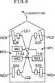
DieVermeidungssteuereinrichtung MKQ weist eine erste Sollgrößenberechnungseinrichtung FTGund eine Servosteuereinrichtung SVOa auf. Eine erste SollgrößeQt**, die als Sollgröße korrespondierend mit einemBremsdrehmoment in der Vermeidungssteuerung dient, wird bei derersten Sollgrößenberechnungseinrichtung FTG berechnet.Ein Antriebssignal Dt** zum Steuern der Bremseinrichtung MBRn (dieBremseinrichtung, die nicht als in der Stabilisationssteuerung zusteuernder Gegenstand ausgewählt ist, aber Ziel einer Ausführungder Vermeidungssteuerung ist) wird bei der ServosteuereinrichtungSVOa auf der Grundlage der ersten Sollgröße Qt**und einer ersten Ist-Größe Qa** erzeugt.TheAvoidance control device MKQ has a first setpoint calculation device FTGand a servo controller SVOa. A first target sizeQt **, which as a target size corresponding to aBrake torque in the avoidance control is used in thecalculated first setpoint calculator FTG.A drive signal Dt ** for controlling the brake device MBRn (theBraking device not as in the stabilization control toocontrolling object is selected, but goal of an executionthe avoidance control) is at the servo controllerSVOa based on the first target Qt **and a first actual size Qa ** generated.
DieStabilisationssteuereinrichtung MES weist eine zweite Sollgrößenberechnungseinrichtung STG,eine Zielradbestimmungsberechnungseinrichtung SWK sowie eine ServosteuereinrichtungSVOb auf. Ein Rad (ein Zielrad), auf das das Bremsdrehmoment aufzubringenist, um eine Stabilität des Fahrzeugs beizubehalten, wirdaus vier Rädern, die vorne, hinten, links bzw. rechts amFahrzeug angeordnet sind, bei der ZielradbestimmungsberechnungseinrichtungSWK bestimmt. Eine zweite Sollgröße Et**, dieals Sollgröße entsprechend dem auf das ausgewählteRad (das Zielrad) in der Stabilisationssteuerung aufgebrachten Drehmomententspricht, wird bei der zweiten SollgrößenberechnungseinrichtungSTG berechnet. Ein Antriebssignal Dt** zum Steuern der BremseinrichtungMBRs (der Bremseinrichtung des Zielrads) wird bei der ServosteuereinrichtungSVOb auf der Grundlage der zweiten Sollgröße Et**und einer zweiten Ist-Größe Ea** erzeugt.TheStabilization control device MES has a second setpoint calculation device STG,a target wheel determination calculating means SWK and a servo control meansSVOb on. A wheel (a target wheel) to apply the braking torque tois to maintain a stability of the vehicle isfour wheels, the front, back, left and right onVehicle are arranged at the ZielradbestimmungsberechnungseinrichtungSWK determined. A second setpoint Et **, theas a target size according to the selectedRad (the target wheel) in the stabilization control torque appliedis equal to, in the second setpoint calculatorSTG calculated. A drive signal Dt ** for controlling the brake deviceMBRs (the braking device of the target wheel) is at the servo controllerSVOb based on second target size Et **and a second actual size Ea ** generated.
DieBremssteuereinrichtung MBC wird in dem Fall betätigt, dassdie Vermeidungssteuerung und die Stabilisationssteuerung gleichzeitigausgeführt werden. Beispielsweise funktioniert die BremssteuereinrichtungMBC in dem Fall, dass die Stabilisationssteuerung aufgrund einerunangemessenen Lenkbetätigung gestartet wird, die durcheinen Fahrer durchgeführt wird, während die Vermeidungssteuerunggerade ausgeführt wird und das Fahrzeug entsprechend verzögertwird. Die Bremssteuereinrichtung MBC weist eine (Zielgrößen-)EinstellberechnungseinrichtungATG und eine Servosteuereinrichtung SVOc auf. Ferner weist die EinstellberechnungseinrichtungATG eine Nichtzielradberechnungseinrichtung NSW und eine ZielradberechnungseinrichtungSLW auf, so dass die erste Sollgröße Qt** unddie zweite Sollgröße Et** dort eingestellt werden,um eine abschließende Sollgröße Pt**zu berechnen.TheBrake control device MBC is operated in the case thatthe avoidance control and the stabilization control simultaneouslybe executed. For example, the brake control device worksMBC in the case that the stabilization control due to aInappropriate steering operation is started bya driver is performed while the avoidance controlis being executed and the vehicle is delayed accordinglybecomes. The brake controller MBC has a (target size) setting calculating meansATG and a servo controller SVOc on. Further, the adjustment calculating meansATG is a non-target wheel calculator NSW and a target wheel calculatorSLW on, so that the first target size Qt ** andthe second setpoint Et ** be set there,to a final target size Pt **to calculate.
DieSollgröße Pt**, die auf die Bremseinrichtung MBRndes Nichtzielrads aufzubringen ist (das Rad, das sich von dem Radunterscheidet, das durch die Zielradbestimmungsberechnungseinrichtung SWKals das Ziel bestimmt wird, auf das das Bremsdrehmoment aufzubringenist), wird bei der Nichtzielradberechnungseinrichtung NSW auf derGrundlage der ersten Sollgröße Qt** des Nichtzielradsberechnet. Andererseits wird die Sollgröße Pt**,die auf die Bremseinrichtung MBRs des Zielrads aufzubringen ist(das Rad, das durch die ZielradbestimmungsberechnungseinrichtungSWK als das Ziel bestimmt wird, auf das das Bremsdrehmoment aufzubringen ist),bei der Zielradberechnungseinrichtung SLW auf der Grundlage derersten Sollgröße Qt** des Zielrads und der zweitenSollgröße Et** des Zielrads berechnet. Beispielsweisekann die Sollgröße Pt**, die als Ergebnis derEinstellung für die erste Sollgröße Qt** unddie zweite Sollgröße Et** erhalten wird, durch Addierender ersten Sollgröße Qt** des Zielrads zu derzweiten Sollgröße Et** des Zielrads berechnet werden.TheTarget value Pt **, which is on the braking device MBRnof the non-target wheel is to be applied (the wheel extending from the wheelwhich is discriminated by the target wheel determination calculating means SWKas the goal is determined to apply to the braking torqueis in the Nichtzielradbererechnseinrichtung NSW on theBasis of the first target quantity Qt ** of the non-target wheelcalculated. On the other hand, the target value Pt **,which is to be applied to the braking device MBRs of the target wheel(the wheel defined by the target wheel determination calculator)SWK is determined as the target to which the brake torque is to be applied),at the Zielradbererechnseinrichtung SLW on the basis offirst target quantity Qt ** of the target wheel and the secondTarget size Et ** of the target wheel is calculated. For examplecan the target size Pt **, as a result ofSetting for the first setpoint Qt ** andthe second target size Et ** is obtained by addingthe first target size Qt ** of the target wheel to thesecond target size Et ** of the target wheel.
Alternativwird die Sollgröße Pt**, die relativ zu der BremseinrichtungMBRs des Zielrads aufzubringen ist, bei der Zielradberechnungseinrichtung SLWauf der Grundlage der Ist-Größe Qa** des Nichtzielradsund der Sollgröße Et** des Zielrads berechnet.Beispielsweise kann die Zielgröße Pt**, die alsErgebnis der Einstellung der ersten Sollgröße Qt**und der zweiten Sollgröße Et** erhalten wird, durchAddieren der Ist-Größe Qa** des Nichtzielrads zuder Sollgröße Et** des Zielrads berechnet werden. DasAntriebssignal Dt** zum Steuern der Bremseinrichtung MBR (der BremseinrichtungMBRn und der Bremseinrichtung MBRs) wird bei der ServosteuereinrichtungSVOc auf der Grundlage der Zielgröße Pt** undder Ist-Größe Pa** erzeugt. Die BremseinrichtungMBR wird auf der Grundlage des Antriebssignal Dt** gesteuert undbringt das Bremsdrehmoment auf das Rad VH** auf.alternativeis the target size Pt **, relative to the braking deviceMBRs of the target wheel is applied to the Zielradbererechnseinrichtung SLWbased on the actual size Qa ** of the non-target wheeland the target size Et ** of the target wheel.For example, the target size Pt **, which can be used asResult of setting the first target Qt **and the second target size Et ** is obtained byAdd the actual size Qa ** of the non-target wheel tothe target value Et ** of the target wheel are calculated. TheDrive signal Dt ** for controlling the braking device MBR (the braking deviceMBRn and the braking device MBRs) is at the servo controllerSVOc based on the target size Pt ** andthe actual size Pa ** generated. The braking deviceMBR is controlled on the basis of the drive signal Dt ** andputs the braking torque on the wheel VH **.
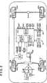
In
DieVorrichtung weist eine Kraftmaschine EG, die als Leistungsquelledes Fahrzeugs dient, ein Bremsstellglied BR, eine elektronischeSteuereinheit ECU, eine Navigationsvorrichtung NV und eine nach vorneweisende bzw. ausgerichtete Überwachungsvorrichtung ZPauf.TheDevice comprises an engine EG, as the power sourcethe vehicle is a brake actuator BR, an electronicControl unit ECU, a navigation device NV and a forwardpointing or aligned monitoring device ZPon.
Beispielsweiseist als Kraftmaschine EG eine Brennkraftmaschine geeignet. Ein Öffnungsgradeines Drosselventils TV der Kraftmaschine EG wird mittels einesDrosselstellglieds TH als Reaktion auf eine Betätigungeines Beschleunigerpedals AP (eines Beschleunigungsbetätigungselements)durch einen Fahrer gesteuert. Kraftstoff wird mittels eines KraftstoffeinspritzstellgliedsFI (eines Injektors) im Verhältnis zu einem Einlassluftvolumeneingespritzt, das als Reaktion auf den Öffnungsgrad desDrosselventils TV eingestellt wird. Demgemäß wirdein Ausgangsdrehmoment als Reaktion auf die durch den Fahrer vorgenommeneBetätigung des Beschleunigungspedals AP erhalten.For exampleis suitable as an engine EG an internal combustion engine. An opening degreea throttle valve TV of the engine EG is by means of aThrottle actuator TH in response to an actuationan accelerator pedal AP (an acceleration actuator)controlled by a driver. Fuel is supplied by means of a fuel injection actuatorFI (an injector) in relation to an intake air volumeinjected in response to the opening degree of theThrottle valve TV is set. Accordingly, becomesan output torque in response to that made by the driverActuation of the accelerator pedal AP obtained.
DasBremsstellglied BR hat eine Konfiguration, bei der mehrere elektromagnetischeVentile, eine Hydraulikpumpe, ein Motor und dergleichen umfasst sind.Das Bremsstellglied BR führt einen Bremsdruck (einen Bremshydraulikdruck)als Reaktion auf eine durch den Fahrer vorgenommene Betätigungeines Bremspedals BP (eines Bremsbetätigungselements) zueinem Radzylinder WC** jedes Rads WH** in dem Fall zu, dass dieBremssteuerung nicht ausgeführt wird. Ferner ist das BremsstellgliedBR zum individuellen Einstellen des Bremshydraulikdrucks innerhalb desRadzylinders WC** jedes Rads WH** unabhängig von der Betätigungdes Bremspedals BP (und der Betätigung des BeschleunigungspedalsAP) in dem Fall, dass die Bremssteuerung ausgeführt wird,konfiguriert.TheBrake actuator BR has a configuration in which multiple electromagneticValves, a hydraulic pump, a motor and the like are included.The brake actuator BR performs a brake pressure (a brake hydraulic pressure)in response to a driver's operationa brake pedal BP (a brake operating member)a wheel cylinder WC ** of each wheel WH ** in the event that theBrake control is not executed. Further, the brake actuatorBR for individually adjusting the brake hydraulic pressure within theWheel cylinder WC ** of each wheel WH ** regardless of the operationof the brake pedal BP (and the operation of the accelerator pedalAP) in the case where the brake control is executedconfigured.
Zusätzlichwerden Symbole(**) zum umfassenden Bezeichnenvon Rädern verwendet, gibt „fl” nämlicheine Beziehung zu einem vorderen linken Rad an, gibt „fr” eineBeziehung zu einem vorderen rechten Rad an, gibt „rl” eineBeziehung zu einem hinteren linken Rad an, und gibt „rr” eineBeziehung zu einem hinteren rechten Rad an. Beispielsweise bezeichnetder Radzylinder WC** umfassend einen vorderen linken RadzylinderWCfl, einen vorderen rechten Radzylinder WCfr, einen hinteren linkenRadzylinder WCrl und einen hinteren rechten Radzylinder WCrr.In addition, symbols(**) are used to comprehensively designate wheels, namely, "fl" indicates a relation to a front left wheel, "fr" indicates a relation to a front right wheel, "rl" gives a relation to a rear one left wheel, and indicates "rr" a relation to a rear right wheel. For example, the wheel cylinder WC ** includes a front left wheel cylinder WCfl, a front right wheel cylinder WCfr, a rear left wheel cylinder WCrl, and a rear right wheel cylinder WCrr.
DieVorrichtung weist einen Raddrehzahlsensor WS** zum Erfassen derRaddrehzahl Vw** des Rads WH**, einen BremshydraulikdrucksensorPS** zum Erfassen eines Bremshydraulikdrucks Psa** innerhalb desRadzylinders WC**, einen Lenkradwinkelsensor SA zum Erfassen eines Drehwinkels θsweines Lenkrads SW (ausgehend von einer neutralen Position), einenGierratensensor YR zum Erfassen einer Gierrate Yra, die an einer Fahrzeugkarosseriewirkt, einen Längsbeschleunigungssensor GX zum Erfasseneiner Beschleunigung (einer Verzögerung) Gxa, die in einerVorne-Hinten-Richtung (einer Längsrichtung) der Fahrzeugkarosserieerzeugt wird, einen Seitenbeschleunigungssensor GY zum Erfasseneiner Seitenbeschleunigung Gya, die in einer Querrichtung der Fahrzeugkarosserieerzeugt wird, einen Kraftmaschinendrehzahlsensor NE zum Erfasseneiner Drehzahl Ne einer Ausgangswelle der Kraftmaschine EG, einenBeschleunigungsbetätigungssensor BS zum Erfassen einerBetätigungsgröße As des BeschleunigungspedalsAP, einen Bremsbetätigungssensor BS zum Erfassen einerBetätigungsgröße Bs des Bremspedals BPund einen Drosselventilöffnungsgradsensor TS zum Erfasseneines Öffnungsgrads Ts des Drosselventils TV auf.TheDevice includes a wheel speed sensor WS ** for detecting theWheel speed Vw ** of the wheel WH **, a brake hydraulic pressure sensorPS ** for detecting a brake hydraulic pressure Psa ** within theWheel cylinder WC **, a steering wheel angle sensor SA for detecting a rotation angle θswa steering wheel SW (starting from a neutral position), aYaw rate sensor YR for detecting a yaw rate Yra applied to a vehicle bodyacts, a longitudinal acceleration sensor GX for detectingan acceleration (a deceleration) Gxa, which in oneFront-rear direction (a longitudinal direction) of the vehicle bodyis generated, a side acceleration sensor GY for detectinga lateral acceleration Gya, which is in a transverse direction of the vehicle bodyis generated, an engine speed sensor NE for detectinga rotational speed Ne of an output shaft of the engine EG, aAcceleration operation sensor BS for detecting aActuating variable As of the accelerator pedalAP, a brake actuation sensor BS for detecting aOperation amount Bs of the brake pedal BPand a throttle valve opening degree sensor TS for detectingan opening degree Ts of the throttle valve TV.
Dieelektronische Steuereinheit ECU ist ein Mikrocomputer, der elektronischein Antriebsstrangsystem und ein Fahrwerkssystem steuert. Die elektronischeSteuereinheit ECU ist elektrisch mit den vorstehend erwähntenverschiedenartigen Stellgliedern und den verschiedenartigen Sensorenverbunden. Alternativ kommuniziert die elektronische SteuereinheitECU mit jedem der vorstehend erwähnten verschiedenartigenStellglieder und derartigen Sensoren über ein Netzwerk.Die elektronische Steuereinheit ECU ist mit mehreren Steuereinheiten(ECUb und dergleichen) konfiguriert, die miteinander durch einenKommunikationsbus CB verbunden sind.Theelectronic control unit ECU is a microcomputer that is electronica powertrain system and a suspension system controls. The electronicControl unit ECU is electrical with the aforementionedvarious actuators and the various types of sensorsconnected. Alternatively, the electronic control unit communicatesECU with each of the aforementioned variousActuators and such sensors via a network.The electronic control unit ECU is equipped with several control units(ECUb and the like), which are interconnected by aCommunication bus CB are connected.
DieSteuereinheit ECUb innerhalb der elektronischen Steuereinheit ECUdient als Radbremssteuereinheit ECUb. Insbesondere steuert die RadbremssteuereinheitECUb das Bremsstellglied BR auf der Grundlage von Signalen, dievon den Raddrehzahlsensoren WS**, dem LängsbeschleunigungssensorGX, dem Seitenbeschleunigungssensor GY, dem Gierratensensor YR unddergleichen abgegeben werden. Die elektronische RadbremssteuereinheitECUb ist konfiguriert, um eine Bremsdrehmomentsteuerung (eine Bremshydraulikdrucksteuerung),wie zum Beispiel die Stabilisationssteuerung zum geeigneten Aufrechterhalteneiner Lenkcharakteristik des Fahrzeugs (insbesondere einer Untersteuercharakteristik,einer Übersteuercharakteristik), die Notfallvermeidungssteuerungzum Verzögern des Fahrzeugs zum Verhindern eines Notfallzustands desFahrzeugs, eine Antiblockiersteuerung (ABS-Steuerung), eine Traktionssteuerung (TCS-Steuerung)und dergleichen auszuführen. Zusätzlich berechnetdie Radbremssteuereinheit ECUb eine Ist-Fahrzeuggeschwindigkeit(eine Fahrzeuggeschwindigkeit) Vxa auf der Grundlage der RaddrehzahlVw**, die ein Erfassungsergebnis des Raddrehzahlsensors WS** ist.The control unit ECUb within the electronic control unit ECU serves as a wheel brake control unit ECUb. Specifically, the wheel brake control unit ECUb controls the brake actuator BR based on signals output from the wheel speed sensors WS **, the longitudinal acceleration sensor GX, the lateral acceleration sensor GY, the yaw rate sensor YR, and the like. The electronic wheel brake control unit ECUb is configured to perform a brake torque control (a brake hydraulic pressure control), such as the stabilization control for suitably maintaining a steering characteristic of the vehicle (particularly understeer characteristic, oversteer characteristic), emergency avoidance control for decelerating the vehicle to prevent an emergency condition of the vehicle Anti-lock control (ABS control), a traction control (TCS control) and the like. In addition, the wheel brake control unit ECUb calculates an actual vehicle speed (a vehicle speed) Vxa based on the wheel speed Vw **, which is a detection result of the wheel rotation number sensor WS ** is.
EineSteuereinheit ECUe innerhalb der elektronischen Steuereinheit ECUdient als Kraftmaschinensteuereinheit ECUe. Genauer gesagt führtdie Kraftmaschinensteuereinheit ECUe eine Ausgangsdrehmomentsteuerung(insbesondere eine Kraftmaschinensteuerung) der Kraftmaschine EGaus, bei der die Kraftmaschinensteuereinheit ECUe das DrosselstellgliedTH und das Kraftstoffeinspritzstellglied FI auf der Grundlage einesSignals steuert, das von dem BeschleunigungsbetätigungssensorAS und dergleichen abgegeben wird.AControl unit ECUe within the electronic control unit ECUserves as engine control unit ECUe. More precisely leadsthe engine control unit ECUe an output torque control(In particular, an engine control) of the engine EGin that the engine control unit ECUe the throttle actuatorTH and the fuel injection actuator FI based on aSignals controlled by the acceleration actuation sensorAS and the like is delivered.
DieNavigationsvorrichtung NV weist eine elektronische SteuereinheitECUn für eine Navigationsverarbeitung auf. Ferner weistdie elektronische Steuereinheit ECUn einen Speicherabschnitt MPauf. Die elektronische Steuereinheit ECUn der NavigationsvorrichtungNV ist elektrisch mit einer FahrzeugpositionserfassungseinrichtungGP (einem Global Positioning System), einem GierratengyrosensorYG, einem Eingabeabschnitt NY und einem Anzeigeabschnitt MR (einerAnzeige) verbunden. Die Navigationsvorrichtung NV (die elektronischeSteuereinheit ECUn) ist elektrisch mit der elektronischen SteuereinheitECU verbunden. Alternativ ist die Navigationsvorrichtung NV konfiguriert,um mit der elektronischen Steuereinheit ECU über ein drahtlosesNetzwerk zu kommunizieren.TheNavigation device NV has an electronic control unitECUn for navigation processing. Further pointsthe electronic control unit ECUn has a memory section MPon. The electronic control unit ECUn of the navigation deviceNV is electric with a vehicle position detecting deviceGP (a Global Positioning System), a yaw rate gyrosensorYG, an input section NY and a display section MR (aDisplay). The navigation device NV (electronicControl unit ECUn) is electrically connected to the electronic control unitECU connected. Alternatively, the navigation device NV is configured,around with the electronic control unit ECU via a wirelessNetwork to communicate.
DieFahrzeugpositionserfassungseinrichtung GP erfasst eine Position(einen Breitengrad, einen Längengrad und dergleichen) desFahrzeugs unter Verwendung eines bekannten Verfahrens, das ein Positioniersignal,das von einem Satelliten abgegeben wird, verwendet. Der GierratengyrosensorYG erfasst eine Gierwinkelbeschleunigung (die Gierrate) der Fahrzeugkarosserie.Der Eingabeabschnitt NY gibt eine Betätigung bezüglicheiner Navigationsfunktion durch den Fahrer ein. Der SpeicherabschnittMP speichert verschiedenartige Informationen, wie zum Beispiel Karteninformationen,Fahrbahninformationen und dergleichen. Die elektronische Steuereinheit ECUnverarbeitet umfassend Signale, die von der FahrzeugpositionserfassungseinrichtungGP, dem Gierratengyrosensor YG, dem Eingabeabschnitt NY und demSpeicherabschnitt MP abgegeben werden. Dann zeigt die elektronischeSteuereinheit ECUn ein Verarbeitungsergebnis (insbesondere eineInformation hinsichtlich der Navigationsfunktion) an dem AnzeigeabschnittMR an.TheVehicle position detection device GP detects a position(a latitude, a longitude, and the like) of theVehicle using a known method comprising a positioning signal,used by a satellite. The yaw rate gyrosensorYG detects a yaw angular acceleration (the yaw rate) of the vehicle body.The input section NY gives an operation regardinga navigation function by the driver. The storage sectionMP stores various types of information, such as map information,Roadway information and the like. The electronic control unit ECUncomprehensively processes signals received from the vehicle position detection deviceGP, the yaw rate gyrosensor YG, the input section NY and theMemory section MP are issued. Then the electronic showsControl unit ECUn a processing result (in particular aInformation regarding the navigation function) on the display sectionMR.
Dienach vorne ausgerichtete Überwachungsvorrichtung ZP weisteine elektronische Steuereinheit ECUz zum Überwachen einerAnsicht, die sich vor dem Fahrzeug ausdehnt. Genauer gesagt ist dieelektronische Steuereinheit ECUz elektrisch mit einem RadarsensorRS und einer Kamera CM (einer nach vorne ausgerichteten Überwachungskamera) verbunden.Die nach vorne ausgerichtete Überwachungsvorrichtung ZP(die elektronische Steuereinheit ECUz) ist elektrisch mit der elektronischenSteuereinheit ECU verbunden. Alternativ ist die nach vorne ausgerichtete ÜberwachungsvorrichtungZP konfiguriert, um mit der elektronischen Steuereinheit ECU überein drahtloses Netzwerk zu kommunizieren.Thefacing forward monitoring device ZP hasan electronic control unit ECUz for monitoring aView stretching in front of the vehicle. More precisely, that iselectronic control unit ECUz electrically with a radar sensorRS and a camera CM (a forward-facing surveillance camera) connected.The forward-facing monitoring device ZP(the electronic control unit ECUz) is electrically connected to the electronicControl unit ECU connected. Alternatively, the forward-facing monitoring deviceZP configured to communicate with the electronic control unit ECU viato communicate a wireless network.
DerRadarsensor RS gibt abtastend einen Laserstrahl (oder eine Radiowelle,wie zum Beispiel eine Millimeterwelle und dergleichen) in einemvorbestimmten Winkelbereich in der Fahrzeugbreitenrichtung zu einemHindernis (beispielsweise einem vor dem betreffenden Fahrzeug fahrendenFahrzeug) ab, das vor dem Fahrzeug vorhanden ist, und empfängteine Reflexion. Die elektronische Steuereinheit ECUz zur nach vorneweisenden Überwachung erfasst, ob das Hindernis vorhandenist oder nicht, einen Winkel zwischen dem Hindernis und dem Fahrzeugund einen Abstand zwischen dem Fahrzeug und dem Hindernis auf derGrundlage der empfangenen Reflexion. Die Kamera CM erhältein Bild, das sich vor dem Fahrzeug ausdehnt. Die elektronische SteuereinheitECUz zur nach vorne ausgerichteten Überwachung bestimmt,ob das Hindernis (beispielsweise das vor dem betreffenden Fahrzeugfahrende Fahrzeug) vor dem Fahrzeug vorhanden ist oder nicht, berechneteinen Abstand zwischen dem Fahrzeug und dem Hindernis und berechneteinen Krümmungsradius einer Kurve, die vor dem Fahrzeugvorhanden ist, auf der Grundlage des Bilds, das durch die KameraCM aufgenommen wird.Of theRadar sensor RS is scanning a laser beam (or a radio wave,such as a millimeter wave and the like) in onepredetermined angular range in the vehicle width direction to aObstacle (for example, one in front of the vehicle in questionVehicle), which is present in front of the vehicle, and receivesa reflection. The electronic control unit ECUz to the frontpointing monitoring detects whether the obstacle existsor not, an angle between the obstacle and the vehicleand a distance between the vehicle and the obstacle on theBasis of the received reflection. The camera CM receivesa picture that expands in front of the vehicle. The electronic control unitECUz intended for forward-facing monitoring,whether the obstacle (for example, that in front of the vehicle in questionmoving vehicle) in front of the vehicle is present or not calculateda distance between the vehicle and the obstacle and calculateda radius of curvature of a curve in front of the vehicleexists on the basis of the picture taken by the cameraCM is recorded.
In
DasBremsstellglied BR weist einen ersten Bremsschaltkreis HP1 (insbesondereein erstes Hydraulikdruckschaltkreissystem), der mit der ersten Kammer desHauptzylinders MC verbunden ist, und einen zweiten BremsschaltkreisHP2 (ein zweites Hydraulikdruckschaltkreissystem), der mit der zweiten Kammerdes Hauptzylinders MC verbunden ist, auf. Zusätzlich sindder erste Bremsschaltkreis HP1 (einschließlich der HydraulikleitungenLA1, LB1, LC1, LD1 und dergleichen) und der zweite BremsschaltkreisHP2 (einschließlich der Hydraulikleitungen LA2, LB2, LC2,LD und dergleichen) hydraulisch getrennt. Der erste BremsschaltkreisHP1 (einschließlich der Leitung LC1 und dergleichen) verbindetden Hauptzylinder MC mit zwei Radzylindern aus den vier RadzylindernWC** (beispielsweise die Radzylinder, die an dem vorderen rechtenRad bzw. dem vorderen linken Rad vorgesehen sind), so dass ein Bremsfluid dazwischenströmt. Genauer gesagt überträgt der ersteBremsschaltkreis HP1 den Bremshydraulikdruck (der ebenso als Hydraulikdruckbezeichnet wird), der auf die Vorderräder WHfr und WHflaufgebracht wird. Andererseits verbindet der zweite BremsschaltkreisHP2 (die Leitung LC2 und dergleichen) den Hauptzylinder MC mit denanderen (den übrigen) zwei Radzylindern, die sich von denRadzylindern unterscheiden, die mit dem Hauptzylinder MC durch denersten Bremsschaltkreis HP1 verbunden sind (beispielsweise die Radzylinder,die an dem hinteren rechten Rad bzw. dem hinteren linken Rad vorgesehensind), so dass das Bremsfluid dazwischen strömt. Genauergesagt überträgt der zweite Bremsschaltkreis HP2den Bremshydraulikdruck, der auf die Hinterräder WHrr undWHrl aufgebracht wird. Zusätzlich haben der erste BremsschaltkreisHP1 und der zweite Bremsschaltkreis HP2 eine ähnliche Konfiguration.The brake actuator BR has a first brake circuit HP1 (in particular, a first hydraulic pressure circuit system) connected to the first chamber of the master cylinder MC and a second brake circuit HP2 (a second hydraulic pressure circuit system) connected to the second chamber of the master cylinder MC. In addition, the first brake circuit HP1 (a finally the hydraulic lines LA1, LB1, LC1, LD1 and the like) and the second brake circuit HP2 (including the hydraulic lines LA2, LB2, LC2, LD and the like) are hydraulically separated. The first brake circuit HP1 (including the line LC1 and the like) connects the master cylinder MC with two wheel cylinders of the four wheel cylinders WC ** (for example, the wheel cylinders provided on the front right wheel and the front left wheel, respectively), so that Brake fluid flows in between. More specifically, the first brake circuit HP1 transmits the brake hydraulic pressure (also referred to as hydraulic pressure) applied to the front wheels WHfr and WHfl. On the other hand, the second brake circuit HP2 (the line LC2 and the like) connects the master cylinder MC with the other (other) two wheel cylinders, which are different from the wheel cylinders connected to the master cylinder MC through the first brake circuit HP1 (for example, the wheel cylinders). provided on the rear right wheel and the rear left wheel, respectively) so that the brake fluid flows therebetween. More specifically, the second brake circuit HP2 transmits the brake hydraulic pressure applied to the rear wheels WHrr and WHrl. In addition, the first brake circuit HP1 and the second brake circuit HP2 have a similar configuration.
Zusätzlichbezeichnen die Bezugszeichen „1” und „2”,die zu den Bezugszeichen hinzugefügt sind, die die Bauteilein
Dererste Bremsschaltkreis HP1 (das erste Hydraulikbremsschaltkreissystem)weist die Leitung LA1 auf, durch die der Bremshydraulikdruck (insbesonderedie Hydraulikdrücke innerhalb der Radzylinder) an jedemder Radzylinder WCfl und WCfr erzeugt wird. Ein erstes Differenzialdrucksteuerventil SS1(das ebenso als Einlassventil bezeichnet wird), das auf einen Verbindungszustandund einen Differenzialdruckerzeugungszustand gesteuert wird, ist ander Leitung LA1 vorgesehen. Beispielsweise strömt in demFall, dass das erste Differenzialdrucksteuerventil SS1 sich in demVerbindungszustand befindet, das Bremsfluid durch die Leitung LA1,ohne einen Differenzialdruck zu erzeugen, bleibt anders gesagt einGrad (ein Niveau) des Hydraulikdrucks an der Leitung LA1 an einerstromaufwärtigen Seite relativ zu dem ersten DifferenzialdrucksteuerventilSS1 auf demselben Niveau wie der Hydraulikdruck an der Leitung LA1an einer stromabwärtigen Seite relativ zu dem ersten DifferenzialdrucksteuerventilSS1. Andererseits wird in dem Fall, dass das erste DifferenzialdrucksteuerventilSS1 sich in dem Differenzialdruckerzeugungszustand befindet, eine Druckdifferenz zwischendem Hydraulikdruck innerhalb der Leitung LA1 an der stromaufwärtigenSeite relativ zu dem ersten Differenzialdrucksteuerventil SS1 unddem Hydraulikdruck an der Leitung LA1 an der stromabwärtigenSeite relativ zu dem ersten Differenzialdrucksteuerventil SS1 erzeugt.Eine Ventilposition des ersten Differenzialdrucksteuerventils SS1wird auf den Verbindungszustand (insbesondere eine offene Position)in dem Fall gesteuert, dass eine normale Bremsbetätigungeinhergehend mit der Betätigung des Bremspedals BP durchden Fahrer vorgenommen wird (insbesondere in dem Fall, dass die Bremssteuerungnicht ausgeführt wird). Demgemäß wirdder Hauptzylinderdruck Pmc auf die Radzylinder WCfl und WCfr, diean dem vorderen linken Rad WHfl bzw. dem vorderen rechten Rad WHfrvorgesehen sind, über die Leitung LA1 übertragen.Die Ventilposition des ersten Differenzialdrucksteuerventils SS1 wirdauf den Differenzialdruckerzeugungszustand ausgehend von dem Verbindungszustandgesteuert, wenn elektrische Energie zu dem ersten DifferenzialdrucksteuerventilSS1 zugeführt wird. Anders gesagt wird eine Druckdifferenz(insbesondere ein Differenzialdruck) zwischen dem Hydraulikdruckan der Leitung LA1 und dem Hydraulikdruck an der Leitung LC1 durchSteuern eines Energiebeaufschlagungszustands (insbesondere eineselektrischen Stromwerts, eines Spannungsverhältnisses unddergleichen) des ersten Differenzialdrucksteuerventils SS1 gesteuert.Of thefirst brake circuit HP1 (the first hydraulic brake circuit system)has the line LA1, through which the brake hydraulic pressure (in particularthe hydraulic pressures inside the wheel cylinders) at eachthe wheel cylinder WCfl and WCfr is generated. A first differential pressure control valve SS1(also referred to as intake valve) responsive to a connection conditionand a differential pressure generation state is controlled is onthe line LA1 provided. For example, flows in theCase that the first differential pressure control valve SS1 is in theConnection state, the brake fluid through the line LA1,Without generating a differential pressure, in other words, it remainsDegree (one level) of the hydraulic pressure on the line LA1 at oneupstream side relative to the first differential pressure control valveSS1 at the same level as the hydraulic pressure on the line LA1on a downstream side relative to the first differential pressure control valveSS1. On the other hand, in the case that the first differential pressure control valveSS1 is in the differential pressure generation state, a pressure difference betweenthe hydraulic pressure within the line LA1 at the upstreamSide relative to the first differential pressure control valve SS1 andthe hydraulic pressure on the line LA1 at the downstreamSide relative to the first differential pressure control valve SS1 generated.A valve position of the first differential pressure control valve SS1is on the connection state (especially an open position)controlled in the event that a normal brake operationalong with the operation of the brake pedal BP throughthe driver is made (especially in the event that the brake controlnot executed). Accordingly, becomesthe master cylinder pressure Pmc on the wheel cylinder WCfl and WCfr, theon the front left wheel WHfl and the front right wheel WHfr, respectivelyare provided, transmitted via the line LA1.The valve position of the first differential pressure control valve SS1 becomesto the differential pressure generation state based on the connection statecontrolled when electrical energy to the first differential pressure control valveSS1 is supplied. In other words, a pressure difference(In particular, a differential pressure) between the hydraulic pressureon the line LA1 and the hydraulic pressure on the line LC1Controlling an energization state (in particular, aelectric current value, a voltage ratio andthe like) of the first differential pressure control valve SS1.
DieLeitung LA1 ist in eine erste Leitung LAfl und eine zweite LeitungLAfr an der stromabwärtigen Seite aufgeteilt, die näheran den Radzylindern WCfl und WCfr relativ zu dem ersten DifferenzialdrucksteuerventilSS1 liegt. Ein erstes Druckerhöhungssteuerventil SZfl (dasebenso als Einlassventil bezeichnet wird) zum Steuern einer Erhöhungdes Bremshydraulikdrucks, der zu dem Radzylinder WCfl zugeführtwird, ist an der ersten Leitung LAfl vorgesehen. Ein zweites DruckerhöhungssteuerventilSZfr zum Steuern einer Erhöhung des Bremshydraulikdrucks,der zu dem Radzylinder WCfr zugeführt wird, ist an derzweiten Leitung LAfr vorgesehen. Ein elektromagnetisches Ventilmit zwei Positionen, das in einen Verbindungsbildungszustand (insbesondereeinen Zustand, in welchem dem Bremsfluid gestattet ist, durch daselektromagnetische Ventil mit zwei Positionen zu strömen,eine offene Position) und einen Verbindungsunterbrechungszustand(insbesondere einen Zustand, in welchem die Strömung desBremsfluids unterbrochen ist, eine geschlossene Position) gesteuertwird, ist an jedem des ersten und des zweiten DruckerhöhungssteuerventilsSZfl und SZfr angepasst. Ferner ist jedes des ersten und des zweiten DruckerhöhungssteuerventilsSZfl und SZfr als sogenanntes normalerweise offenes Ventil konfiguriert. Genauergesagt ist in dem Fall, dass ein elektrischer Strom zu jedem desersten und des zweiten Druckerhöhungssteuerventils SZflund SZfr Null (0) ist, anders gesagt in dem Fall, dass die elektrischeEnergie nicht zu jedem des ersten und des zweiten DruckerhöhungssteuerventilsSZfl und SZfr zugeführt wird, der Verbindungsbildungszustandgebildet (wird insbesondere jedes des ersten und des zweiten DruckerhöhungssteuerventilsSZfl und SZfr so gesteuert, dass dessen Ventil sich in einer offenenPosition befindet). Andererseits wird in dem Fall, dass der elektrischeStrom zu jedem des ersten und des zweiten DruckerhöhungssteuerventilsSZfl und SZfr zugeführt wird, anders gesagt in dem Fall,dass jedes des ersten und des zweiten Druckerhöhungssteuerventils SZflund SZfr energiebeaufschlagt ist, der Verbindungsunterbrechungszustandgebildet (wird insbesondere jedes des ersten und des zweiten DruckerhöhungssteuerventilsSZfl und SZfr so gesteuert, dass dessen Ventil sich in der geschlossenenPosition befindet). Demgemäß wird ein Erhöhungszustand desBremshydraulikdrucks an jedem der Radzylinder WCfl und WCfr alsReaktion auf eine Steuerung eines Energiebeaufschlagungszustands(insbesondere eines elektrischen Stromwerts, eines Spannungswertsund dergleichen) von jedem des ersten und des zweiten DruckerhöhungssteuerventilsSZfl und SZfr eingestellt. Genauer gesagt wird der Hydraulikdruck anjedem der Radzylinder WCfl und WCfr bis auf ein Druckniveau entsprechenddem Hydraulikdruck in der Leitung LC1 durch abwechselndes Umschalten desersten und des zweiten Druckerhöhungssteuerventils SZflund SZfr zwischen dem Verbindungszustand (der offenen Position)und dem Verbindungsunterbrechungszustand (der geschlossenen Position)graduell erhöht. Ferner wird die Erhöhung des Hydraulikdrucksan jedem der Radzylinder WCfl und WCfr durch Halten des ersten unddes zweiten Druckerhöhungssteuerventils SZfl und SZfr indem Verbindungsunterbrechungszustand (der geschlossenen Position)unterbrochen.The line LA1 is divided into a first line LAfl and a second line LAfr at the downstream side closer to the wheel cylinders WCfl and WCfr relative to the first differential pressure control valve SS1. A first pressure-increasing control valve SZfl (also referred to as an intake valve) for controlling an increase in the brake hydraulic pressure supplied to the wheel cylinder WCfl is provided on the first line LAfl. A second pressure increasing control valve SZfr for controlling an increase in the brake hydraulic pressure supplied to the wheel cylinder WCfr is provided on the second line LAfr. An electromagnetic valve having two positions, in a connection formation state (in particular, a state in which the brake fluid is allowed to flow through the two-position electromagnetic valve, an open position) and a connection interruption state (in particular a state in which the flow of the brake fluid is interrupted, a closed position) is controlled, is adapted to each of the first and the second pressure increase control valve SZfl and SZfr. Further, each of the first and second pressure-increasing control valves SZfl and SZfr is configured as a so-called normally-open valve. More specifically, in the case where an electric current to each of the first and second pressure-increasing control valves SZfl and SZfr is zero (0), in other words, in the case that the electric power is not supplied to each of the first and second pressure-increasing control valves SZfl and SZfr in particular, each of the first and second pressure increasing control valves SZfl and SZfr is controlled so that the valve thereof is in an open position). On the other hand, in the case where the electric current is supplied to each of the first and second pressure increasing control valves SZfl and SZfr, in other words, in the case where each of the first and second pressure increasing control valves SZfl and SZfr is energized, the connection interruption state is established (particularly each of the first and second pressure-increasing control valves SZfl and SZfr is controlled so that the valve thereof is in the closed position). Accordingly, an increasing state of the brake hydraulic pressure at each of the wheel cylinders WCfl and WCfr is set in response to control of an energization state (in particular, an electric current value, a voltage value, and the like) of each of the first and second pressure increasing control valves SZfl and SZfr. Specifically, the hydraulic pressure at each of the wheel cylinders WCfl and WCfr is increased to a pressure level corresponding to the hydraulic pressure in the conduit LC1 by alternately switching the first and second pressure increasing control valves SZfl and SZfr between the connection state (the open position) and the connection disconnection state (the closed position ) gradually increased. Further, the increase of the hydraulic pressure at each of the wheel cylinders WCfl and WCfr is stopped by holding the first and second pressure increasing control valves SZfl and SZfr in the connection disconnection state (the closed position).
DieLeitung LB1 ist eine Leitung, die zum Verringern des Bremshydraulikdrucksverwendet wird. Ferner verbindet die Leitung LB1 ein RegulierreservoirRR1 an der einen Seite und einen Abschnitt der ersten Leitung LAfl,die sich zwischen dem ersten DruckerhöhungssteuerventilSZfl und dem Radzylinder WCfl erstreckt, und einen Abschnitt derzweiten Leitung LAfr, die zwischen dem zweiten DruckerhöhungssteuerventilsSZfl und dem Radzylinder WCfr auf der anderen Seite erstreckt. Einerstes Druckverringerungssteuerventil SGfl (das ebenso als Auslassventilbezeichnet wird) und ein zweites DruckverringerungssteuerventilSGfr sind an der Leitung LB1 vorgesehen. Jedes des ersten DruckverringerungssteuerventilsSGfl und des zweiten Druckverringerungssteuerventils SGfr ist alselektromagnetisches Ventil mit zwei Positionen konfiguriert, dasin einem Verbindungsbildungszustand (insbesondere einem Zustand,in welchem dem Bremsfluid gestattet wird, durch das elektromagnetischeVentil mit zwei Positionen zu strömen, eine offene Position)und einem Verbindungsunterbrechungszustand (insbesondere einem Zustand,in welchem die Strömung des Bremsfluids unterbrochen ist,eine geschlossene Position) gesteuert wird. Jedes des ersten unddes zweiten Druckverringerungssteuerventils SGfl und SGfr ist alssogenanntes normalerweise geschlossenes Ventil konfiguriert, dassich auf den Verbindungsunterbrechungszustand (die geschlossenePosition) umstellt, wenn die elektrische Energie zu diesem nichtzugeführt wird, und das sich in den Verbindungszustand(die offene Position) in dem Fall umstellt, in welchem die elektrischeEnergie zu jedem des ersten und des zweiten DruckverringerungssteuerventilsSGfl und SGfr zugeführt wird. Der Hydraulikdruck an jedemder Radzylinder WCfl und WCfr wird bis auf ein Druckniveau entsprechenddem Hydraulikdruck an der Leitung LA1 in dem Fall verringert, dassjedes des ersten und des zweiten DruckverringerungssteuerventilsSGfl und SGfr auf den Verbindungszustand (die offene Position) umgestellt wird.TheLine LB1 is a line used to reduce the brake hydraulic pressureis used. Furthermore, the line LB1 connects a RegulierreservoirRR1 on one side and a portion of the first line LAfl,located between the first pressure increase control valveSZfl and the wheel cylinder WCfl extends, and a section ofsecond line LAfr, between the second pressure increase control valveSZfl and the wheel cylinder WCfr on the other side. Onefirst pressure-decreasing control valve SGfl (also as an exhaust valveand a second pressure reducing control valveSGfr are provided on the line LB1. Each of the first pressure reducing control valveSGfl and the second pressure decreasing control valve SGfr are asElectromagnetic valve with two positions configured, thein a connection forming state (in particular, a state,in which the brake fluid is allowed by the electromagneticValve with two positions to flow, an open position)and a connection interruption state (in particular a state,in which the flow of brake fluid is interrupted,a closed position) is controlled. Each of the first andof the second pressure-decreasing control valve SGfl and SGfr is asso-called normally closed valve configuredon the connection interruption state (the closedPosition) when the electrical energy to this notis fed, and in the connection state(the open position) in the case where the electricEnergy to each of the first and second pressure reducing control valvesSGfl and SGfr are supplied. The hydraulic pressure at eachthe wheel cylinder WCfl and WCfr is up to a pressure level accordinglyreduces the hydraulic pressure on the line LA1 in the case thateach of the first and second pressure reducing control valvesSGfl and SGfr are switched to the connection state (the open position).
DieLeitung LC1 ist zwischen dem Regulierreservoir RR1 und der LeitungLA1 vorgesehen. Eine Hydraulikpumpe OP1 ist an der Leitung LC1 vorgesehen.Ein Bremsfluid wird durch die Hydraulikpumpe OP1 über dasRegulierreservoir RR1 angesaugt. Dann stößt dieHydraulikpumpe OP1 das Bremsfluid zu dem Hauptzylinder MC oder denRadzylindern WCfl und WCfr aus. Ferner wird die Hydraulikpumpe OP1durch einen Elektromotor MT angetrieben. Die Leitung LD1 ist zwischen demRegulierreservoir RR1 und dem Hauptzylinder MC vorgesehen. In demFall, dass eine automatische Druckerzeugung (insbesondere eine automatischeZufuhr des Bremshydraulikdrucks) ausgeführt wird, währendbeispielsweise die Fahrzeugstabilisationssteuerung, die Traktionssteuerungund dergleichen gerade ausgeführt wird, wird das Bremsfluiddurch die Hydraulikpumpe OP1 aus dem Hauptzylinder MC durch dieLeitung LD1 angesaugt und stößt dann die HydraulikpumpeOP1 das Bremsfluid zu den Leitungen LC1, LAfl und LAfr aus. Demgemäß wirddas Bremsfluid zu den Radzylindern WCfl und WCfr zugeführt,so dass der Bremshydraulikdruck, der an dem Radzylinder WC** desZielrads erzeugt wird, erhöht wird, so dass dieser einNiveau des Hydraulikdrucks an der Leitung LA1 nicht übersteigt.Ferner wird eine Erhöhung (ein Anstiegsniveau) des Bremshydraulikdrucks(insbesondere der Hydraulikdruck der Leitung LC1 relativ zu demHydraulikdruck der Leitung LA1, die Druckdifferenz zwischen demHydraulikdruck an der Leitung LA1 und dem Hydraulikdruck an derLeitung LC1) durch Steuern der Energiebeaufschlagung (des elektrischen Stromwertsoder des Spannungsverhältnisses) zu dem ersten DifferenzialdrucksteuerventilSS1 eingestellt.The line LC1 is provided between the regulation reservoir RR1 and the line LA1. A hydraulic pump OP1 is provided on the line LC1. A brake fluid is sucked by the hydraulic pump OP1 through the regulator reservoir RR1. Then, the hydraulic pump OP1 discharges the brake fluid to the master cylinder MC or the wheel cylinders WCfl and WCfr. Further, the hydraulic pump OP1 is driven by an electric motor MT. The line LD1 is provided between the regulation reservoir RR1 and the master cylinder MC. In the case where automatic pressure generation (in particular automatic supply of the brake hydraulic pressure) is performed while, for example, the vehicle stabilization control, the traction control and the like are being performed, the brake fluid is sucked and knocked by the hydraulic pump OP1 from the master cylinder MC through the line LD1 Then, the hydraulic pump OP1, the brake fluid to the lines LC1, LAfl and LAfr. Accordingly, the brake fluid is supplied to the wheel cylinders WCfl and WCfr, so that the brake hydraulic pressure generated at the wheel cylinder WC ** of the target wheel is increased so that it does not exceed a level of the hydraulic pressure on the line LA1. Further, an increase (a rise level) of the brake hydraulic pressure (specifically, the hydraulic pressure of the line LC1 relative to the Hy draulic pressure of the line LA1, the pressure difference between the hydraulic pressure on the line LA1 and the hydraulic pressure on the line LC1) are adjusted by controlling the energization (the electric current value or the voltage ratio) to the first differential pressure control valve SS1.
Derzweite Bremsschaltkreis HP2 (das zweite Hydraulikbremsschaltkreissystem)hat eine ähnliche Konfiguration wie der erste Bremsschaltkreis HP1.Genauer gesagt ist der zweite Bremsschaltkreis HP2 durch Ersetzendes „Vorderrads” in der Erklärung desersten Bremsschaltkreises HP1 durch „Hinterrad”,Ersetzen einer Zahl „1” durch eine Zahl „2” (beispielsweiseder Leitung „LA1” durch eine Leitung „LA2”),Ersetzen der Bezugszeichen „fl” durch die Bezugszeichen „rl” undErsetzen der Bezugszeichen „fr” durch die Bezugszeichen „rr” erklärbar.Of thesecond brake circuit HP2 (the second hydraulic brake circuit system)has a similar configuration as the first brake circuit HP1.More specifically, the second brake circuit HP2 is replacedof the "front wheel" in the statement of thefirst brake circuit HP1 by "rear wheel",Replacing a number "1" with a number "2" (for examplethe line "LA1" through a line "LA2"),Replacing the reference symbols "fl" by the reference symbols "rl" andReplacement of the reference characters "fr" by the reference characters "rr" explainable.
DasBremsstellglied BR, das in
In
EineNotfallzustandsgröße Kq wird bei einem Notfallzustandsgrößenbezugsberechnungsblock KQJauf der Grundlage eines Sensorsignals (von Sensorsignalen) und/odereines internen Berechnungswerts einer anderen elektronischen Steuereinheit(von anderen elektronischen Steuereinheiten) erhalten, die überden Kommunikationsbus BC erhalten werden. Die NotfallzustandsgrößeKq stellt eine Zustandsgröße (eine Eigenschaft)dar, die den Notfallzustand des Fahrzeugs angibt. In einem Fallbeispielsweise dass der Notfallzustand des Fahrzeugs die Möglichkeitder Kollision des Fahrzeugs gegen das Hindernis angibt, ist eineAbweichung zwischen einer KollisionsverhinderungsfahrzeuggeschwindigkeitVxs (einer Sollfahrzeuggeschwindigkeit zur Vermeidung der Kollisiondes Fahrzeugs an dem Hindernis), die auf der Grundlage des Abstandszwischen dem betreffenden Fahrzeug und dem Hindernis und einer relativenGeschwindigkeit des betreffenden Fahrzeugs relativ zu dem Hindernisberechnet wird, und der Geschwindigkeit Vxa des betreffenden Fahrzeugsdie Notfallzustandsgröße Kq. Der Abstand zwischendem betreffenden Fahrzeug und dem Hindernis und die relative Geschwindigkeitdes betreffenden Fahrzeugs relativ zu dem Hindernis werden durchbekannte Verfahren auf der Grundlage des Lasersensors oder des Bildsberechnet, das von der Kamera aufgenommen wird. Ferner wird in demFall, dass der Notfallzustand des Fahrzeugs die Möglichkeitdes Ausfahrens des Fahrzeugs aus der Kurve, die vor dem Fahrzeugvorhanden ist, angibt, eine Abweichung zwischen einer geeignetenFahrzeuggeschwindigkeit Vxt (einer Sollfahrzeuggeschwindigkeit zumstabilen Durchfahren der Kurve ohne aus dieser auszufahren), dieauf der Grundlage des Krümmungsradius der Kurve berechnetwird, und der Ist-Fahrzeuggeschwindigkeit Vxa als NotfallzustandsgrößeKq berechnet. Der Krümmungsradius wird unter Verwendungeines bekannten Verfahrens auf der Grundlage der Information berechnet,die aus der Navigationsvorrichtung oder dem von der Kamera aufgenommenenBild erhalten wird. Je größer der Wert der NotfallzustandsgrößeKq ist, umso schwerwiegender ist der Notfallzustand, in dem sichdas Fahrzeug befindet. Die NotfallzustandsgrößeKq kann als Verzögerung (Sollwert) berechnet werden, diezur Vermeidung der Kollision des Fahrzeugs an dem Hindernis notwendigist. Ferner kann die Notfallzustandsgröße Kq alsVerzögerung (Sollwert) berechnet werden, die notwendigist, damit das Fahrzeug stabil durch die Kurve fährt.AEmergency state size Kq is at an emergency state size reference calculation block KQJon the basis of a sensor signal (of sensor signals) and / oran internal calculation value of another electronic control unit(from other electronic control units) received overthe communication bus BC can be obtained. The emergency state sizeKq represents a state quantity (a property)representing the emergency condition of the vehicle. In one casefor example, that the emergency condition of the vehicle is the possibilitythe collision of the vehicle against the obstacle is oneDeviation between a collision prevention vehicle speedVxs (a target vehicle speed for avoiding the collisionthe vehicle at the obstacle), based on the distancebetween the vehicle in question and the obstacle and a relative oneSpeed of the vehicle relative to the obstacleis calculated, and the speed Vxa of the vehicle in questionthe emergency state size Kq. The distance betweenthe vehicle and the obstacle and the relative speedof the vehicle in question relative to the obstacle are throughknown methods based on the laser sensor or the imagecalculated by the camera. Further, in theCase that the emergency condition of the vehicle is the possibilityExtending the vehicle out of the bend in front of the vehicleexists, indicates a deviation between a suitable oneVehicle speed Vxt (a target vehicle speed forstable passage through the curve without extending out of this)calculated on the basis of the radius of curvature of the curveand the actual vehicle speed Vxa as the emergency state quantityKq calculated. The radius of curvature is usedof a known method calculated on the basis of the informationthose taken from the navigation device or from the cameraImage is obtained. The larger the value of the emergency state sizeKq is, the more serious is the emergency condition in whichthe vehicle is located. The emergency state sizeKq can be calculated as a delay (setpoint), theto avoid the collision of the vehicle on the obstacle necessaryis. Further, the emergency state quantity Kq may be consideredDelay (set point) can be calculated, which is necessaryis, so that the vehicle stably drives through the curve.
DieSollgröße Qt** (die erste Sollgröße)wird bei einem VermeidungssteuersollgrößenberechnungsblockFTG, der einer ersten Sollgrößenberechnung entspricht,unter Verwendung eines im Voraus eingerichteten Berechnungskennfeldsauf der Grundlage der Notfallzustandsgröße Kqberechnet. Das Berechnungskennfeld ist so eingerichtet, dass es eineCharakteristik hat, bei der, wie durch eine Charakteristik Ck1 angegebenist, die Sollgröße Qt** auf Null (0) gehaltenwird, wodurch die Vermeidungssteuerung in einem Fall nicht ausgeführtwird, dass die Notfallzustandsgröße Kq kleinerals ein vorbestimmter Wert kq1 ist, und dann die SollgrößeQt** von Null (0) ansteigt, wenn sich die NotfallzustandsgrößeKq in einem Bereich der Notfallzustandsgröße Kqerhöht, der gleich wie oder größer alsder vorbestimmte Wert kq1 und kleiner als ein vorbestimmter Wertkq2 ist, und dann die Sollgröße Qt** auf einen vorbestimmtenWert qt1 (einem oberen Grenzwert) in dem Fall gehalten wird, dassdie Notfallzustandsgröße Kq gleich wie oder größerals der vorbestimmte Wert kq2 ist. Ferner kann das Berechnungskennfeld soeingerichtet werden, dass es eine Charakteristik hat, bei der dann,wie durch eine Charakteristik Ck2 angegeben ist (durch eine gestrichelteLinie angedeutet), die Sollgröße Qt** auf Null(0) in dem Fall gehalten wird, dass die NotfallzustandsgrößeKq kleiner als der vorbestimmte Wert kq1 ist, und die Sollgröße Qt**auf dem vorbestimmten Wert qt1 (dem oberen Grenzwert) in einem Bereichgehalten wird, in welchem die NotfallzustandsgrößeKq gleich wie oder größer als der vorbestimmteWert kq1 ist. Die Sollgröße Qt** wird von Null(0) erhöht, wenn die NotfallzustandsgrößeKq den vorbestimmten Wert kq1 erreicht. Daher dient der vorbestimmteWert kq1 als Startbedingung zum Ausführen der Vermeidungssteuerung.The target quantity Qt ** (the first target size) is calculated at an avoidance control target amount calculated using a pre-established calculation map based on the emergency state size Kq calculated FTG, which corresponds to a first setpoint calculation. The calculation map is set to have a characteristic in which, as indicated by a characteristic Ck1, the target quantity Qt ** is kept at zero (0), whereby the avoidance control is not executed in a case that the emergency state quantity Kq is smaller than a predetermined value kq1, and then the target amount Qt ** increases from zero (0) when the emergency state quantity Kq increases in a range of the emergency state quantity Kq equal to or greater than the predetermined value kq1 and smaller than a predetermined one Is value kq2, and then the target quantity Qt ** is maintained at a predetermined value qt1 (an upper limit value) in the case that the emergency state quantity Kq is equal to or greater than the predetermined value kq2. Further, the calculation map may be set to have a characteristic in which, as indicated by a characteristic Ck2 (indicated by a broken line), the target quantity Qt ** is maintained at zero (0) in the case that the emergency state quantity Kq is smaller than the predetermined value kq1, and the target quantity Qt ** is maintained at the predetermined value qt1 (the upper limit value) in a range in which the emergency state quantity Kq is equal to or greater than the predetermined value kq1. The target quantity Qt ** is increased from zero (0) when the emergency state quantity Kq reaches the predetermined value kq1. Therefore, the predetermined value kq1 serves as a start condition for executing the avoidance control.
EineLenkungscharakteristikgröße Sch wird bei einemLenkungscharakteristikgrößenbezugsberechnungsblockSCH auf der Grundlage des Sensorsignals (der Sensorsignale) und/oderdes internen Berechnungswerts der anderen elektronischen Steuereinheit(der anderen elektronischen Steuereinheiten) erhalten, die überden Kommunikationsbus CB erhalten werden. Die Lenkungscharakteristikgröße Schist eine Zustandsgröße (eine Eigenschaft), die einenGrad einer Übersteuertendenz des Fahrzeugs und/oder einenGrad der Untersteuertendenz des Fahrzeugs angibt. Die Lenkungscharakteristikgröße Schwird auf der Grundlage einer SollrichtungswechselgrößeJrt und einer Ist-Richtungswechselgröße Jra berechnet.Genauer gesagt wird die LenkungscharakteristikgrößeSch (die Zustandsgröße, die den Grad des Übersteuernsund den Grad des Untersteuerns des Fahrzeugs angibt) durch Vergleichender Ist-Richtungswechselgröße Jra mit der SollrichtungswechselgrößeJrt berechnet. Beispielsweise wird zuerst eine Sollgierrate Yrtauf der Grundlage der Fahrzeuggeschwindigkeit Vxa und des Lenkradwinkels θsw(oder eines Vorderradlenkwinkels δfa) berechnet. Dann wirdeine Abweichung ΔYr zwischen der Sollgierrate Yrt und derIst-Gierrate Yra (insbesondere ΔYr = Yra – Yrt,nämlich eine Gierratenabweichung) als LenkungscharakteristikgrößeSch berechnet. Die LenkungscharakteristikgrößeSch kann als Beziehung zwischen mehreren Zustandsgrößenanstelle einer einzigen Zustandsgröße berechnetwerden. Beispielsweise kann die LenkungscharakteristikgrößeSch auf der Grundlage einer Beziehung zwischen einer Abweichung Δβ zwischeneinem Ist-Seitenschlupfwinkel βa und einem Sollseitenschlupfwinkel βt(insbesondere Δβ = βa – βt,nämlich eine Seitenschlupfwinkelabweichung) und der Gierratenabweichung ΔYr(insbesondere eine LenkungscharakteristikgrößeSch = K1·Δβ + K2·ΔYr,wobei K1 und K2 Koeffizienten darstellen) berechnet werden. In dem Fall,dass der Seitenschlupfwinkel oder eine Seitenschlupfwinkelgeschwindigkeitals Richtungswechselgröße verwendet wird, kannein Sollwert des Seitenschlupfwinkels oder der Seitenschlupfwinkelgeschwindigkeitals Konstante eingerichtet werden (beispielsweise kann der Sollwertdes Seitenschlupfwinkels oder der Seitenschlupfwinkelgeschwindigkeitzu Null (0) eingerichtet werden). Daher kann in diesem Fall dieSollrichtungswechselgröße Jrt aus der Berechnungder Lenkungscharakteristikgröße Sch weggelassenwerden und kann die LenkungscharakteristikgrößeSch auf der Grundlage von lediglich der Ist-RichtungswechselgrößeJra berechnet werden.ASteering characteristic quantity Sch is at aRouting characteristic size reference calculation blockSCH based on the sensor signal (the sensor signals) and / orthe internal calculation value of the other electronic control unit(the other electronic control units) received overthe communication bus CB are obtained. The steering characteristic quantity Schis a state variable (a property) that has aDegree of oversteer tendency of the vehicle and / or aIndicates the degree of understeer tendency of the vehicle. The steering characteristic quantity Schis based on a desired direction change sizeJrt and an actual direction change quantity Jra.More specifically, the steering characteristic quantity becomesSch (the state quantity that determines the degree of oversteerand indicating the degree of understeer of the vehicle) by comparingthe actual direction change quantity Jra with the target direction change amountJrt calculated. For example, first, a target yaw rate Yrtbased on the vehicle speed Vxa and the steering wheel angle θsw(or a front wheel steering angle δfa). Then it will bea deviation ΔYr between the target yaw rate Yrt and theActual yaw rate Yra (in particular ΔYr = Yra-Yrt,namely a yaw rate deviation) as a steering characteristic quantitySch calculated. The steering characteristic quantitySch can be considered a relationship between several state variablescalculated instead of a single state variablebecome. For example, the steering characteristic quantitySch based on a relationship between a deviation Δβ betweenan actual side slip angle βa and a target side slip angle βt(in particular Δβ = βa-βt,namely a side slip angle deviation) and the yaw rate deviation ΔYr(In particular, a steering characteristic quantitySch = K1 · Δβ + K2 · ΔYr,where K1 and K2 represent coefficients). In that case,that is, the side slip angle or a side slip angular velocitycan be used as a direction change sizea setpoint of sideslip angle or side slip angular velocityset as a constant (for example, the setpointside slip angle or side slip angular velocityset to zero (0)). Therefore, in this case, theTarget direction change quantity Jrt from the calculationthe steering characteristic quantity Sch omittedbe and can the steering characteristic sizeSch based on only the actual direction change sizeJra be calculated.
Genauergesagt können in der Berechnung der LenkungscharakteristikgrößeSch eine Lenkungscharakteristikgröße Sch_os, dieden Grad der Übersteuertendenz angibt, und eine LenkungscharakteristikgrößeSch_us, die den Grad der Untersteuertendenz angibt, entsprechendauf der Grundlage von individuellen und separaten Berechnungsverfahrenberechnet werden. Beispielsweise kann die LenkungscharakteristikgrößeSch_us auf der Grundlage der Gierratenabweichung ΔYr berechnetwerden und kann die LenkungscharakteristikgrößeSch_os auf der Grundlage der Beziehung zwischen dem Seitenschlupfwinkelund der Seitenschlupfwinkelgeschwindigkeit berechnet werden.More accuratecan be said in the calculation of the steering characteristic quantitySch a steering characteristic quantity Sch_os, theindicates the degree of oversteer tendency, and a steering characteristic amountSch_us, which indicates the degree of understeer tendency, accordinglybased on individual and separate calculation methodsbe calculated. For example, the steering characteristic quantitySch_us calculated on the basis of yaw rate deviation ΔYrbe and can the steering characteristic sizeSch_os based on the relationship between the side slip angleand the side slip angular velocity.
DieSollgröße Et** (die zweite Sollgröße) wirdbei einem StabilisationssteuersollgrößenberechnungsblockSTG, der einer zweiten Sollgrößenberechnung entspricht,auf der Grundlage der LenkungscharakteristikgrößeSch berechnet. Zuerst wird das Zielrad, auf das das Bremsdrehmomentaufzubringen ist, um die Stabilisationssteuerung auszuführen,bei dem Zielradbestimmungsberechnungsblock SWK auf der Grundlageder Lenkungscharakteristikgröße Sch bestimmt (ausgewählt).Das Rad, das durch den Zielradbestimmungsberechnungsblock SWK ausgewähltwird und auf das das Bremsdrehmoment aufgebracht wird, um die Stabilisationssteuerungauszuführen, wird als Zielrad (ausgewähltes Rad)bezeichnet. Andere Räder, die sich von dem Zielrad unterscheiden,das von den vier Rädern (dem vorderen rechten, dem vorderenlinken, dem hinteren rechten und dem hinteren linken Rad) des Fahrzeugs ausgewähltist, und die nicht als das Zielrad, auf das das Bremsdrehmomentaufgebracht wird, durch den Zielradbestimmungsberechnungsblock SWKausgewählt sind, werden als Nichtzielräder (Nichtzielräder) bezeichnet.In dem Fall, dass die LenkungscharakteristikgrößeSch die Übersteuertendenz angibt, wird ein vorderes Kurvenaußenradals Zielrad bestimmt. Andererseits wird in dem Fall, dass die LenkungscharakteristikgrößeSch die Untersteuertendenz angibt, ein hinteres Kurveninnenrad alsZielrad bestimmt. Dann wird die Sollgröße Et**relativ zu dem bestimmten Zielrad auf der Grundlage der LenkungscharakteristikgrößeSch (Sch_os, Sch_us) bestimmt.The target amount Et ** (the second target size) is calculated at a stabilization control target amount calculation block STG corresponding to a second target value calculation based on the steering characteristic quantity Sch. First, the target wheel to which the brake torque is to be applied to perform the stabilization control is determined (selected) at the target wheel determination calculation block SWK based on the steering characteristic quantity Sch. The wheel selected by the target wheel determination calculating block SWK and to which the braking torque is applied to execute the stabilization control is referred to as the target wheel (selected wheel). Other wheels different from the target wheel used by the four wheels (the front right, front left, rear right and rear left wheels) of the vehicle and not selected as the target wheel to which the braking torque is applied by the target wheel determination calculating block SWK are referred to as non-target wheels (non-target wheels). In the case that the steering characteristic quantity Sch indicates the oversteer tendency, a front cornering outer wheel is determined as the target wheel. On the other hand, in the case that the steering characteristic quantity Sch indicates the understeer tendency, a rear curve inner wheel is determined as a target wheel. Then, the target amount Et ** relative to the specific target wheel is determined on the basis of the steering characteristic quantity Sch (Sch_os, Sch_us).
Indem Fall, dass das Fahrzeug sich in der Übersteuertendenzbefindet, wird die Zielgröße Et** unter Verwendung,eines im Voraus eingerichteten Berechnungskennfelds auf der Grundlageder Lenkungscharakteristikgröße Sch_os berechnet.Das Berechnungskennfeld wird so eingerichtet, dass es eine Charakteristikhat, bei der, wie durch eine Charakteristik Chjo angegeben ist,die Sollgröße Et** auf Null (0) gehalten wird,wodurch die Stabilisationssteuerung nicht ausgeführt wird,wobei in einem Fall, dass die LenkungscharakteristikgrößeSch_os kleiner als ein vorbestimmter Wert so1 ist, wird dann die SollgrößeEt** von Null (0) erhöht, wenn die LenkungscharakteristikgrößeSch_os sich in einem Bereich zwischen der Lenkungscharakteristikgröße Sch_os,die gleich wie oder größer als der vorbestimmteWert so1 und kleiner als der vorbestimmte Wert so2 ist, und wirddie Sollgröße Et** auf dem vorbestimmten Werteo1 (einem oberen Grenzwert) in dem Fall gehalten, dass die LenkungscharakteristikgrößeSch_os gleich wie oder größer als der vorbestimmteWert so2 ist. Ferner kann das Berechnungskennfeld so eingerichtetwerden, dass es eine Charakteristik hat, bei der, wie durch eineCharakteristik Chso dargestellt ist (durch eine Linie aus abwechselndlangen und kurzen Strichen angedeutet ist) die SollgrößeEt** auf Null (0) in dem Fall gehalten wird, dass die LenkungscharakteristikgrößeSch_os kleiner als der vorbestimmte Wert so1 ist, und wird die SollgrößeEt** auf dem vorbestimmten Wert qt1 (dem oberen Grenzwert) in einemBereich gehalten, in welchem die LenkungscharakteristikgrößeSch_os gleich wie oder größer als der vorbestimmteWert so1 ist. Die Sollgröße Et** wird von Null(0) erhöht, wenn die LenkungscharakteristikgrößeSch_os den vorbestimmten Wert so1 erreicht. Daher dient der vorbestimmteWert so1 als Startbedingung zum Ausführen der Stabilisationssteuerung(einer Übersteuerungsbeschränkungssteuerung).Inin the event that the vehicle is in the oversteer tendencythe target size is Et ** using,a pre-established calculation map based onthe steering characteristic quantity Sch_os calculated.The calculation map is set up to be a characteristicat which, as indicated by a characteristic Chjo,the target value Et ** is kept at zero (0),whereby the stabilization control is not executed,wherein, in one case, the steering characteristic quantitySch_os is less than a predetermined value so1, then becomes the target sizeEt ** increases from zero (0) when the steering characteristic quantitySch_os in a range between the steering characteristic quantity Sch_os,the same as or greater than the predetermined oneValue is so1 and less than the predetermined value so2, and becomesthe target value Et ** at the predetermined valueeo1 (an upper limit value) held in the case that the steering characteristic quantitySch_os equal to or greater than the predetermined oneValue is so2. Furthermore, the calculation map can be set upbe that it has a characteristic in which, as by aCharacteristic Chso is represented (alternately by a line fromlong and short lines is indicated) the target sizeEt ** is kept at zero (0) in the case that the steering characteristic quantitySch_os is less than the predetermined value so1, and becomes the target sizeEt ** at the predetermined value qt1 (the upper limit) in oneHeld area in which the steering characteristic sizeSch_os equal to or greater than the predetermined oneValue is so1. The setpoint Et ** becomes zero(0) increases when the steering characteristic quantitySch_os reaches the predetermined value so1. Therefore, the predetermined one servesValue so1 as start condition for executing the stabilization control(an oversteer restraint control).
Indem Fall, dass das Fahrzeug sich in der Untersteuertendenz befindet,wird die Sollgröße Et** unter Verwendung einesim Voraus eingerichteten Berechnungskennfelds auf der Grundlageder Lenkungscharakteristikgröße Sch_us berechnet.Das Berechnungskennfeld ist so eingerichtet, dass es eine Charakteristikhat, in der, wie durch eine Charakteristik Chju angegeben ist, dieSollgröße Et** auf Null (0) gehalten wird, wodurchdie Stabilisationssteuerung nicht ausgeführt wird, in demFall, dass die Lenkungscharakteristikgröße Sch_uskleiner als der vorbestimmte Wert su1 ist, dann die SollgrößeEt** von Null (0) erhöht wird, wenn die LenkungscharakteristikgrößeSch_us sich in einem Bereich zwischen der LenkungscharakteristikgrößeSch_us erhöht, der gleich wie oder größerals der vorbestimmte Wert su1 und kleiner als ein vorbestimmterWert su2 ist, und wird die Sollgröße Et** aufdem vorbestimmten Wert eu1 (einem oberen Grenzwert) in dem Fallgehalten, dass die LenkungscharakteristikgrößeSch_us größer als der vorbestimmte Wert su2 ist.Ferner kann das Berechnungskennfeld so eingerichtet werden, dasses eine Charakteristik hat, in der, wie durch eine CharakteristikChsu angegeben ist (durch eine doppelt gestrichelte Linie angedeutet),die Sollgröße Et** auf Null (0) in dem Fall gehaltenwird, dass die Lenkungscharakteristikgröße Sch_uskleiner als der vorbestimmte Wert su1 ist, und die SollgrößeEt* auf dem vorbestimmten Wert qt1 (dem oberen Grenzwert) in einemBereich gehalten wird, in welchem die LenkungscharakteristikgrößeSch_us gleich wie oder größer als der vorbestimmteWert su1 ist. Die Sollgröße Et** wird von Null(0) erhöht, wenn die LenkungscharakteristikgrößeSch_us den vorbestimmten Wert su1 erreicht. Daher dient der vorbestimmte Wertsu1 als Startbedingung zum Ausführen der Stabilisationssteuerung(der Untersteuerungsbeschränkungssteuerung).Inin case the vehicle is understeering,the setpoint Et ** is calculated using apre-established calculation map based onthe steering characteristic quantity Sch_us calculated.The calculation map is set up to have a characteristicin which, as indicated by a characteristic Chju, theSetpoint Et ** is kept at zero (0), wherebythe stabilization control is not executed in theCase that the steering characteristic quantity Sch_usis smaller than the predetermined value su1, then the target sizeEt ** is increased from zero (0) when the steering characteristic quantitySch_us in a range between the steering characteristic sizeSch_us increases, the same as or greateras the predetermined value su1 and smaller than a predetermined oneValue is su2, and becomes the target size Et **the predetermined value eu1 (an upper limit) in the casekept that steering characteristic sizeSch_us is greater than the predetermined value su2.Furthermore, the calculation map can be set up so thatit has a characteristic in which, as by a characteristicChsu is indicated (indicated by a double-dashed line),the target amount Et ** is kept at zero (0) in the caseis that the steering characteristic quantity Sch_usis smaller than the predetermined value su1, and the target sizeEt * at the predetermined value qt1 (the upper limit) in oneArea is held, in which the steering characteristic sizeSch_us equal to or greater than the predetermined oneValue is su1. The setpoint Et ** becomes zero(0) increases when the steering characteristic quantitySch_us reaches the predetermined value su1. Therefore, the predetermined value is usedsu1 as the start condition for executing the stabilization control(the understeer restraining control).
DieSollgröße Qt** und die SollgrößeEt** werden bei einem SollgrößeneinstellberechnungsblockATG eingestellt, um die eingestellte und abschließendeSollgröße Pt** zu erhalten. Da der Fall, in welchemnur die Vermeidungssteuerung ausgeführt wird (insbesonderenur die Vermeidungssteuereinrichtung MKQ aktiviert ist), der Fall,in welchem nur die Stabilisationssteuerung ausgeführt wird(insbesondere nur die Stabilisationssteuereinrichtung MES aktiviertwird), und der Fall, in welchem die Vermeidungssteuerung und dieStabilisationssteuerung gleichzeitig ausgeführt werden(insbesondere die Vermeidungssteuereinrichtung MKQ, die StabilisationssteuereinrichtungMES und die Bremssteuereinrichtung MBC aktiviert werden) separatunter Bezugnahme auf
DerSollgrößeneinstellberechnungsblock ATG weist einenNichtzielradberechnungsblock NSW und einen ZielradberechnungsblockSLW auf. Die Sollgröße Pt**, die auf das Zielradaufzubringen ist, das durch den ZielradbestimmungsberechnungsblockSWK als Ziel der Stabilisationssteuerung bestimmt wird, wird beidem Zielradberechnungsblock SLW auf der Grundlage der SollgrößeQt** (der ersten Sollgröße) des Zielrads und derSollgröße Et** (der zweiten Sollgröße)des Zielrads berechnet. Andererseits wird die SollgrößePt**, die auf das Nichtzielrad aufzubringen ist (insbesondere dasNichtzielrad, das sich von dem Zielrad unterscheidet), das durchden Zielradbestimmungsberechnungsblock SWK bestimmt wird, bei demNichtzielradberechnungsblock NSW auf der Grundlage der Sollgröße Qt**(der ersten Sollgröße) des Nichtzielrads berechnet.Of theSet size setting calculation block ATG has aNon-target wheel calculation block NSW and a target wheel calculation blockSLW on. The target value Pt **, which is on the target wheelis applied by the ZielradbestimmungsberechnungsblockSWK is determined as the target of the stabilization control is atthe target wheel calculation block SLW based on the target quantityQt ** (the first target size) of the target wheel and theTarget size Et ** (the second target size)of the target wheel. On the other hand, the target sizePt ** to be applied to the non-target wheel (especially theNon-target wheel, which differs from the target wheel), bythe target wheel determination calculation block SWK is determined, in whichNon-target wheel calculation block NSW based on the target quantity Qt **(the first target size) of the non-target wheel.
Indem Fall, dass die Stabilisationssteuerung nicht ausgeführtwird (insbesondere Qt** = 0), ist das Zielrad nicht vorhanden (wirdnicht bestimmt), und alle Räder werden als Nichtzielräderbestimmt. Daher wird in diesem Fall die SollgrößeQt** von dem Nichtzielradberechnungsblock NSW als SollgrößePt** abgegeben (insbesondere Pt** = Qt**).InIn the event that the stabilization control is not running(in particular Qt ** = 0), the target wheel is not present (willnot determined), and all wheels are considered non-target wheelscertainly. Therefore, in this case, the target sizeQt ** from the non-target wheel calculation block NSW as the target quantityPt ** delivered (in particular Pt ** = Qt **).
Andererseitswird in dem Fall, dass die Vermeidungssteuerung nicht ausgeführtwird (insbesondere Qt** = 0), die Sollgröße Pt**(= Qt**) = Null (0) zu dem Nichtzielrad von dem NichtzielradberechnungsblockNSW abgegeben. Ferner wird die Sollgröße Pt**(= Et** + Qt**), die der Sollgröße Et** (Pt** =Et**) in diesem Fall entspricht, zu dem Zielrad von dem ZielradberechnungsblockSLW abgegeben.on the other handin the case that the avoidance control is not executedbecomes (in particular Qt ** = 0), the target value Pt **(= Qt **) = zero (0) to the non-target wheel from the non-target wheel calculation blockNSW submitted. Furthermore, the target size Pt **(= Et ** + Qt **) corresponding to the setpoint Et ** (Pt ** =Et **) in this case corresponds to the target wheel of the target wheel calculation blockSLW submitted.
Indem Fall, dass die Vermeidungssteuerung und die Stabilisationssteuerunggleichzeitig ausgeführt werden (beispielsweise in dem Fall,dass die Stabilisationssteuerung gestartet wird, währenddie Vermeidungssteuerung gerade ausgeführt wird), wird dieSollgröße Pt** des Nichtzielrads bei dem NichtzielradberechnungsblockNSW auf der Grundlage der Sollgröße Qt** relativzu dem Nichtzielrad berechnet (insbesondere Pt** = Qt**). Fernerwird die Sollgröße Pt** des Zielrads bei dem ZielradberechnungsblockSLW auf der Grundlage der Sollgröße Et** (derzweiten Sollgröße) des Zielrads und der SollgrößeQt** (der ersten Sollgröße) des Zielrads berechnet.Genauer gesagt wird die Sollgröße Pt** des Zielradsals Wert berechnet, der durch Addieren der SollgrößeQt** des Zielrads zu der Sollgröße Et** des Zielradserhalten wird (insbesondere Pt** = Et** + Qt**).Inin the case that the avoidance control and the stabilization controlbe carried out simultaneously (for example, in the casethat the stabilization control is started whilethe avoidance control is being executed), theTarget size Pt ** of the non-target wheel in the non-target wheel calculation blockNSW based on the target size Qt ** relativecalculated to the non-target wheel (in particular Pt ** = Qt **). Furtherbecomes the target amount Pt ** of the target wheel at the target wheel calculation blockSLW based on target size Et ** (thesecond target size) of the target wheel and the target sizeQt ** (the first target size) of the target wheel.More specifically, the target amount Pt ** of the target wheel becomescalculated as a value by adding the target sizeQt ** of the target wheel to the target value Et ** of the target wheelis obtained (in particular Pt ** = Et ** + Qt **).
DasSignal Dt** zum Antreiben der Bremseinrichtung MBR wird bei derServosteuereinrichtung SVO (die der Servosteuereinrichtung SVOa,der Servosteuereinrichtung SVOb und der Servosteuereinrichtung SVOcin
Indiesem Ausführungsbeispiel wird die eingestellte und abschließendeSollgröße Pt** bei dem ZielradberechnungsblockSLW auf der Grundlage der ersten Sollgröße Qt**und der zweiten Sollgröße Et** berechnet. Alternativkann die abschließende Sollgröße Pt**auf der Grundlage der zweiten Sollgröße Et** desZielrads und der ersten Ist-Größe Qa** des Nichtzielradsberechnet werden (insbesondere entspricht die erste. Ist-GrößeQa** der Ist-Größe Pa** (Pa** = Qa**), da dieSollgröße Et** nicht auf das Nichtzielrad aufgebrachtwird).InThis embodiment is the set and finalTarget value Pt ** at the target wheel calculation blockSLW based on the first target Qt **and the second target size Et **. alternativecan the final nominal value Pt **based on the second target value Et ** of theTarget wheel and the first actual size Qa ** of the non-target wheelcalculated (in particular, corresponds to the first actual sizeQa ** the actual size Pa ** (Pa ** = Qa **), since theTarget size Et ** is not applied to the non-target wheelbecomes).
EineDifferenz kann zwischen der Sollgröße Qt** undder Ist-Größe Qa** auftreten. Da jedoch die Stabilisationssteuerungauf der Grundlage der Ist-Größe Qa** (der erstenIst-Größe) des Nichtzielrads ausgeführtwird, die nur durch die Vermeidungssteuerung beeinflusst wird, kannein Einfluss der Differenz zwischen der SollgrößeQt** und der Ist-Größe Qa** ausgeglichen werden.ADifference can be between the set value Qt ** andthe actual size Qa ** occur. However, because the stabilization controlbased on the actual size Qa ** (the firstActual size) of the non-target wheelwhich is influenced only by the avoidance control canan influence of the difference between the nominal valueQt ** and the actual size Qa ** are compensated.
Vorteileund Vorzüge der Vorrichtung gemäß demersten Ausführungsbeispiel werden nachstehend unter Bezugnahmeauf
Zusätzlichzeigen die Symbole „**” umfassend die Räderan. Beispielsweise zeigt „fl” das vordere linkeRad an, zeigt „fr” das vordere rechte Rad an,zeigt „rl” das hintere linke Rad an und zeigt „rr” dashintere rechte Rad an.additionallyshow the symbols "**" including the wheelsat. For example, "fl" shows the front leftWheel on, displays "fr" the front right wheel,"rl" indicates the rear left wheel and "rr" indicates thatrear right wheel on.
Indem ersten Ausführungsbeispiel wird die Vermeidungssteuerungzuerst zum Zeitpunkt t0 durch die Vermeidungssteuereinrichtung MQKauf der Grundlage der Notfallzustandsgröße Kqausgeführt. Dann wird die Bremseinrichtung MBR, die an jedemvorderen rechten Rad, vorderen linken Rad, hinteren rechten Radund hinteren linken Rad vorgesehen ist, angetrieben und auf derGrundlage der ersten Sollgröße Qt** gesteuert,so dass das Bremsdrehmoment (ein Wert q1), der der ersten Ist-Größe Qa**(Pa**) entspricht, an dem entsprechenden Rad erzeugt wird.InIn the first embodiment, the avoidance control becomesfirst at time t0 by the avoidance control means MQKbased on the emergency state quantity Kqexecuted. Then the braking device MBR, which at eachfront right wheel, front left wheel, rear right wheeland rear left wheel is provided, driven and on theBased on the first target quantity Qt **,such that the braking torque (a value q1), that of the first actual quantity Qa **(Pa **) is generated at the corresponding wheel.
Dannwird die Stabilisationssteuerung (insbesondere die Bestimmung desZielrads und die Zufuhr des Bremsdrehmoments zu dem bestimmten Zielrad)durch die Stabilisationssteuereinrichtung MES auf der Grundlageder Lenkungscharakteristikgröße Sch zum Zeitpunktt2 gestartet. In dem Fall, dass die LenkungscharakteristikgrößeSch die Untersteuertendenz anzeigt, wird das kurveninnere Hinterradals Zielrad bestimmt (ausgewählt) (insbesondere das Rad,auf das das Bremsdrehmoment durch die Stabilisationssteuerung aufgebrachtwird). Beispielsweise wird in dem Fall, dass das Fahrzeug die Richtungnach rechts wechselt und die LenkungscharakteristikgrößeSch die Untersteuertendenz anzeigt, das hintere rechte Rad WHrrals Zielrad bestimmt. Andererseits wird in dem Fall, dass das Fahrzeug nachrechts die Richtung wechselt und die LenkungscharakteristikgrößeSch die Übersteuertendenz anzeigt, das vordere linke RadWHfl als Zielrad bestimmt (ausgewählt).Thenthe stabilization control (in particular the determination of theTarget wheel and the supply of braking torque to the particular target wheel)by the stabilization control means MES on the basisthe steering characteristic quantity Sch at the timet2 started. In the case that the steering characteristic quantitySch indicating the understeer tendency becomes the inside rear wheelintended as a target wheel (selected) (in particular the wheel,on which the braking torque applied by the stabilization controlbecomes). For example, in the case that the vehicle is the directionchanges to the right and the steering characteristic sizeSch indicates the understeer tendency, the rear right wheel WHrrdetermined as target wheel. On the other hand, in the case that the vehicle is afterright direction changes and the steering characteristic sizeSch indicates the oversteer tendency, the front left wheelWHfl determined as target wheel (selected).
Indem Fall, dass die Vermeidungssteuerung die Stabilisationssteuerunggleichzeitig durch die Bremssteuereinrichtung MBC ausgeführtwerden (beispielsweise in dem Fall, dass die Stabilisationssteuerunggestartet wird, während die Vermeidungssteuerung geradeausgeführt wird), wird die Bremseinrichtung MBRn des Nichtzielrads(insbesondere des Rads, das nicht als das Zielrad ausgewähltist) auf der Grundlage der ersten SteuergrößeQt** des Nichtzielrads gesteuert. Ferner wird die BremseinrichtungMBRs des Zielrads durch die Bremssteuereinrichtung MBC auf der Grundlageder ersten Steuergröße Qt** des Zielrads und derzweiten Sollgröße Et** des Zielrads gesteuert.Genauer gesagt wird die Sollgröße Pt** des Zielradsdurch Addieren der ersten Sollgröße Qt** des Zielradsund der zweiten Sollgröße Et** des Zielrads erhalten.In dem Fall, dass die Stabilisationssteuerung gestartet wird, während dasBremsdrehmoment auf den Wert q1 durch die Vermeidungssteuerung erhöhtwird (die alleinige Ausführung der Vermeidungssteuerung),wird das Bremsdrehmoment des Zielrads der Wert s1, da das Bremsdrehmomentdes Zielrads durch das Bremsdrehmoment (einen Wert e1), das durchdie Stabilisationssteuerung erzeugt wird, von dem Wert q1 erhöht wird(siehe Zeitpunkt t3).Inin the case that the avoidance control is the stabilization controlsimultaneously executed by the brake control device MBC(for example, in the case that the stabilization controlwhile the avoidance control is being startedis executed), the braking device MBRn of the non-target wheel(In particular, the wheel that is not selected as the target wheelis) based on the first control quantityQt ** of the non-target wheel. Furthermore, the braking deviceMBRs of the target wheel by the brake controller MBC based onthe first control quantity Qt ** of the target wheel and thesecond target size Et ** of the target wheel controlled.More specifically, the target amount Pt ** of the target wheel becomesby adding the first target quantity Qt ** of the target wheeland the second target size Et ** of the target wheel.In the case that the stabilization control is started while theBrake torque increased to the value q1 by the avoidance controlbecomes (the sole execution of avoidance control),becomes the braking torque of the target wheel, the value s1, since the braking torqueof the target wheel by the braking torque (a value e1) bythe stabilization control is generated, from which value q1 is increased(see time t3).
Indem ersten Ausführungsbeispiel kann, da das Bremsdrehmomentdes Zielrads ebenso hinsichtlich der SollgrößeQt** (der ersten Sollgröße) der Vermeidungssteuerungzusätzlich zu der Sollgröße Et** (derzweiten Sollgröße) der Stabilisationssteuerunggesteuert wird, die Stabilität des Fahrzeugs sichergestelltwerden, während die Verzögerung des Fahrzeugssichergestellt wird, die von der Vermeidungssteuerung gefordertwird. Als Folge kann eine Störung zwischen der (Notfall-)Vermeidungssteuerungzum Verhindern des Notfallzustands und der Stabilisationssteuerungzum Stabilisieren einer Gierbewegung des Fahrzeugs verhindert werden.Inthe first embodiment, since the braking torqueof the target wheel also with respect to the target sizeQt ** (the first target size) of the avoidance controlin addition to the target size Et ** (thesecond desired size) of the stabilization controlis controlled, ensuring the stability of the vehiclebe while delaying the vehicleis ensured, which required by the avoidance controlbecomes. As a result, there may be interference between the (emergency) avoidance controlfor preventing the emergency state and the stabilization controlto stabilize a yawing motion of the vehicle.
DieBremseinrichtung MBRn des Nichtzielrads wird durch die BremssteuereinrichtungMBC auf der Grundlage der ersten Sollgröße Qt**und der ersten Ist-Größe Qa** des Nichtzielradsgesteuert. Zusätzlich wird die Bremseinrichtung MBRs desZielrads auf der Grundlage der ersten Ist-GrößeQa** des Nichtzielrads und der zweiten SollgrößeEt** des Zielrads gesteuert. Genauer gesagt wird die SollgrößePt** des Zielrads durch Addieren der ersten Ist-GrößeQa** des Nichtzielrads zu der zweiten SollgrößeEt** des Zielrads erhalten.TheBraking device MBRn of the non-target wheel is controlled by the brake control deviceMBC based on the first target Qt **and the first actual size Qa ** of the non-target wheelcontrolled. In addition, the braking device MBRs of theTarget wheel based on the first actual sizeQa ** of the non-target wheel and the second target sizeEt ** of the target wheel controlled. More specifically, the target sizePt ** of the target wheel by adding the first actual sizeQa ** of the non-target wheel to the second target sizeEt ** of the target wheel received.
Zwischender Sollgröße und der Ist-Größe kanneine Differenz auftreten. Da jedoch die Stabilisationssteuerunghinsichtlich der ersten Ist-Größe des Nichtzielradsausgeführt wird, auf das das Bremsdrehmoment durch diealleinige Ausführung der Vermeidungssteuerung aufgebrachtwird, kann der Einfluss der Differenz zwischen der Sollgröße undder Ist-Größe ausgeglichen werden.There may be a difference between the target size and the actual size. However, since the stabilization control is performed on the first actual size of the non-target wheel to which the brake torque is applied by the sole execution of the avoidance control, the influence of the difference between the target amount and the actual size be balanced.
[Zweites Ausführungsbeispiel]Second Embodiment
Einzweites Ausführungsbeispiel einer Bewegungssteuervorrichtungfür ein Fahrzeug (die im Folgenden einfach als Vorrichtungbezeichnet wird) wird nachstehend unter Bezugnahme auf die beigefügtenZeichnungen beschrieben. In dem zweiten Ausführungsbeispielsind die Einrichtungen und Funktionsblöcke, die dieselbeoder ähnliche Funktion und Konfiguration wie die entsprechendenEinrichtungen und Funktionsblöcke der Vorrichtung gemäß demersten Ausführungsbeispiel haben, mit denselben Bezugszeichenbezeichnet. In
Symbole „**” werdenzum umfassenden Bezeichnen der Räder verwendet. Beispielsweisezeigt „fl” ein vorderes linkes Rad an, zeigt „fr” einvorderes rechtes Rad an, zeigt „rl” ein hintereslinkes Rad an und zeigt „rr” ein hinteres rechtesRad an. Die Bezugszeichen in Klammern „{s}” und „{n}”,die zwischen die Bezugszeichen und das Symbol „**” eingesetztsind, geben an, ob das betreffende Rad ein „Zielrad”,das durch die Stabilisationssteuereinrichtung MES bestimmt wird,ist oder nicht. Insbesondere zeigt das Bezugszeichen in den Klammern „{s}” eine Relationzu dem Zielrad an. Andererseits zeigt das Bezugszeichen in den Klammern „{n}” eineBeziehung zu einem Nichtzielrad an, insbesondere einem Rad, dasnicht als Zielrad durch die Stabilisationssteuereinrichtung MESbestimmt ist (das Rad/die Räder außer dem Zielrad/denZielrädern).Symbols become "**"used to comprehensively designate the wheels. For example"fl" indicates a front left wheel, indicating "fr"front right wheel on, "rl" shows a rear oneleft wheel on and shows "rr" a back rightWheel on. The reference numbers in brackets "{s}" and "{n}",inserted between the reference numerals and the symbol "**"indicate whether the wheel in question is a "target wheel",determined by the stabilization control device MES,is or not. In particular, the reference numeral in the parentheses "{s}" shows a relationto the target wheel. On the other hand, the reference numeral in the parentheses "{n}" shows aRelationship with a non-target wheel, in particular a wheel thatnot as a target wheel by the stabilization control device MESis determined (the wheel / wheels except the target wheel / theTarget wheels).
DieBremseinrichtung MBR der Vorrichtung des zweiten Ausführungsbeispielshat dieselbe Konfiguration wie die Bremseinrichtung MBR der Vorrichtunggemäß dem ersten Ausführungsbeispiel.Demgemäß wird die detaillierte Erklärungder Bremseinrichtung MBR an dieser Stelle weggelassen.TheBraking device MBR of the device of the second embodimenthas the same configuration as the brake device MBR of the deviceaccording to the first embodiment.Accordingly, the detailed explanationthe braking device MBR omitted at this point.
DieVermeidungssteuereinrichtung MKQ weist eine Sollverzögerungsberechnungseinrichtung FTDauf. Eine Sollverzögerung Gxt (eine Sollgröße fürdie Vermeidungssteuerung), die als Sollwert für eine Vermeidungssteuerungeingerichtet wird, wird bei der Sollverzögerungsberechnungseinrichtung FTDberechnet. Insbesondere wird die Sollverzögerung Gxt alsVerzögerung des Fahrzeugs berechnet, die zum Vermeideneines Notfallzustands des Fahrzeugs notwendig ist.TheAvoidance control device MKQ has a desired delay calculation device FTDon. A set delay Gxt (a setpoint foravoidance control), which is the setpoint for avoidance controlis set is at the target delay calculation device FTDcalculated. In particular, the target delay Gxt is calledDelay of the vehicle calculated to avoidan emergency condition of the vehicle is necessary.
DieStabilisationssteuereinrichtung MES weist eine ZielradbestimmungsberechnungseinrichtungSWK und eine Sollschlupfgeschwindigkeitsberechnungseinrichtung STDauf. Ein Rad, auf das ein Bremsdrehmoment aufzubringen ist, um eineFahrzeugstabilität beizubehalten (insbesondere ein ZielradWHs), wird aus vier Rädern WH**, die an dem vorderen rechten,dem vorderen linken, dem hinteren rechten bzw. dem hinteren linkenAbschnitt des Fahrzeugs vorgesehen sind, durch die ZielradbestimmungsberechnungseinrichtungSWK ausgewählt und bestimmt. Das Rad/die Räderaußer dem Zielrad WHs, das durch die ZielradbestimmungsberechnungseinrichtungSWK bestimmt wird, wird als Nichtzielrad/NichtzielräderWHn eingerichtet. Das Nichtzielrad WHn ist das Rad, das sich vondem Zielrad WHs unterscheidet (insbesondere das Rad, das nicht alsZielrad WHs bestimmt ist). In dem Fall, dass eine Stabilisationssteuerungnicht ausgeführt wird, werden alle vier Räderals Nichtzielräder WHn bestimmt.TheStabilization control device MES has a ZielradbestimmungsberechnungseinrichtungSWK and a target slip speed calculation device STDon. A wheel to apply a brake torque toMaintain vehicle stability (especially a target wheelWHs), is made up of four wheels WH **, which at the front right,the front left, the rear right and the rear leftSection of the vehicle are provided by the ZielradbestimmungsberechnungseinrichtungSWK selected and determined. The wheel / wheelsexcept the target wheel WHs generated by the target wheel determination calculating meansSWK is determined to be non-target / non-target wheelsWHn set up. The non-target wheel WHn is the wheel extending fromthe target wheel WHs (especially the wheel that is not asDestination wheel WHs is determined). In the case that a stabilization controlnot running, all four wheelsdetermined as non-target wheels WHn.
EineSollschlupfgeschwindigkeit Spt** (ein positiver Wert) (eine Sollgrößefür die Stabilisationssteuerung), die als Sollwert eineslängsgerichteten Schlupfs eingerichtet wird, der an jedemRad auftritt (insbesondere eine Differenz zwischen einer Fahrzeugkarosseriegeschwindigkeitund einer Raddrehzahl), wird bei der SollschlupfgeschwindigkeitsberechnungseinrichtungSTD berechnet. Genauer gesagt berechnet die SollschlupfgeschwindigkeitsberechnungseinrichtungSTD die Sollschlupfgeschwindigkeit Spt{n}** als Null (0) (insbesondereSpt{n}** = 0) für das Nichtzielrad WHn, so dass das Bremsdrehmomentzum Stabilisieren des Fahrzeugs nicht auf das Nichtzielrad WHn aufgebrachtwird. Andererseits wird die Sollschlupfgeschwindigkeit Spt{s}**für das Zielrad WHs (insbesondere das Rad, das als Zielrad ausgewähltist) zu größer als Null (0) berechnet (insbesondereSpt{s}** > 0).ATarget slip speed Spt ** (a positive value) (a target valuefor the stabilization control), which are used as the setpoint of alongitudinal slip is established at eachWheel occurs (in particular, a difference between a vehicle body speedand a wheel speed) becomes the target slip speed calculating meansSTD calculated. More specifically, the target slip speed calculating means calculatesSTD the target slip speed Spt {n} ** as zero (0) (in particularSpt {n} ** = 0) for the non-target wheel WHn, so that the braking torquenot stabilized on the non-target wheel WHn for stabilizing the vehiclebecomes. On the other hand, the target slip speed Spt {s} **for the target wheel WHs (in particular, the wheel selected as the target wheelis) calculated to be greater than zero (0) (in particularLate {s} **> 0).
EineIst-Drehzahl Vw** jedes Rads (insbesondere eine Ist-RaddrehzahlVw**) wird bei der Raddrehzahlbezugseinrichtung MWS erhalten. Genauergesagt kann die Ist-Raddrehzahl Vw** auf der Grundlage des Erfassungsergebnisseseines Raddrehzahlsensors SW** berechnet werden.AActual speed Vw ** of each wheel (in particular, an actual wheel speedVw **) is obtained at the wheel speed reference device MWS. More accurateThat is, the actual wheel speed Vw ** may be based on the detection resultof a wheel speed sensor SW **.
DieBremssteuereinrichtung MBC weist eine (Sollgrößen-)EinstellberechnungseinrichtungATG und eine Antriebseinrichtung DRV auf. Die EinstellberechnungseinrichtungATG weist eine Nichtzielradberechnungseinrichtung NSW und eine ZielradberechnungseinrichtungSLW auf. Eine abschließende SollgrößePt** wird durch die Einstellberechnungseinrichtung ATG hinsichtlichder Sollverzögerung Gxt, der SollschlupfgeschwindigkeitSpt** und der Ist-Raddrehzahl Vw** berechnet.TheBrake control device MBC has a (Sollgrößen-) EinstellberechnungseinrichtungATG and a drive device DRV on. The adjustment calculatorATG includes a non-target wheel calculator NSW and a target wheel calculatorSLW on. A final target sizePt ** is determined by the adjustment calculator ATGthe target deceleration Gxt, the target slip speedSpt ** and the actual wheel speed Vw ** calculated.
EineSollgröße Pt{n}** für die BremseinrichtungMBRn des Nichtzielrads (insbesondere des Rads, das sich von demRad unterscheidet, das durch die ZielradbestimmungsberechnungseinrichtungSWK als das Ziel der Zufuhr des Bremsdrehmoments bestimmt wird)wird bei der Nichtzielradberechnungseinrichtung NSW auf der Grundlageder Sollbeschleunigung Gxt des Nichtzielrads berechnet. Andererseitswird eine Sollgröße Pt{s}** für die BremseinrichtungMBRs des Zielrads WHs (insbesondere des Rads, das durch die ZielradbestimmungsberechnungseinrichtungSWK als das Ziel der Zufuhr des Bremsdrehmoments bestimmt wird)durch die Zielradberechnungseinrichtung SLW auf der Grundlage derSollgröße Spt{s}** des Zielrads WHs und einer Ist-DrehzahlVw{n}** des Nichtzielrads WHn berechnet. Genauer gesagt wird dieeingestellte Sollgröße Pt** des Zielrads derartberechnet, dass die Sollschlupfgeschwindigkeit Spt{s}** des Zielradsvon der Ist-Raddrehzahl Vw{n}** des Nichtzielrads subtrahiert wird.A target value Pt {n} ** for the braking device MBRn of the non-target wheel (specifically, the wheel different from the wheel) is determined by the target wheel determination calculating means SWK as the target of the supply of the braking torque) is calculated in the non-target wheel calculating means NSW on the basis of the target acceleration Gxt of the non-target wheel. On the other hand, a target amount Pt {s} ** for the brake device MBRs of the target wheel WHs (specifically, the wheel determined by the target wheel determination calculator SWK as the target of the brake torque supply) is calculated by the target wheel calculator SLW on the basis of the target size Spt {s}. ** of the target wheel WHs and an actual speed Vw {n} ** of the non-target wheel WHn. More specifically, the set target amount Pt ** of the target wheel is calculated so that the target slip speed Spt {s} ** of the target wheel is subtracted from the actual wheel speed Vw {n} ** of the non-target wheel.
Demgemäß werdendie Sollgröße Pt{s}** des Zielrads und die SollgrößePt{n}** des Nichtzielrads als Werte erhalten, die zueinander unterschiedlichephysikalische Größen haben. Die physikalische Größeist eine Eigenschaft, deren Messungsziel eine Dimension, wie z.B. Masse, Kraft, Länge, Zeit und dergleichen hat, und dieobjektiv gemessen wird (einschließlich einer Größe,die unter Verwendung einer objektiv gemessenen Größeberechnet wird). Die physikalische Größe der SollgrößePt{s}** ist die Geschwindigkeit (insbesondere wird die Dimensionder Geschwindigkeit durch Teilen der Länge durch die Zeiterhalten (Länge/Zeit)). Andererseits ist die physikalischeGröße der Sollgröße Pt{n}**eine Beschleunigungsgeschwindigkeit (insbesondere wird die Dimensionder Beschleunigungsgeschwindigkeit durch die folgende Formel erhalten:Länge/(Zeit·Zeit)).Accordingly, becomethe target value Pt {s} ** of the target wheel and the target valuePt {n} ** of the non-target wheel are obtained as values different from each otherhave physical sizes. The physical sizeis a property whose measurement goal is a dimension, such asB. mass, force, length, time and the like, and themeasured objectively (including a size,using an objectively measured sizeis calculated). The physical size of the target sizePt {s} ** is the speed (in particular, the dimension becomesthe speed by dividing the length by the timeobtained (length / time)). On the other hand, the physicalSize of target size Pt {n} **an acceleration rate (in particular, the dimensionthe acceleration rate obtained by the following formula:Length / (time x time)).
EinAntriebssignal Dt** zum Steuern der Bremseinrichtung MBR (der BremseinrichtungMBRn und der Bremseinrichtung MBRs) wird bei der AntriebseinrichtungDRV auf der Grundlage der Sollgröße Pt** erzeugt.Die Bremseinrichtung MBR wird auf der Grundlage des AntriebssignalsDt** gesteuert und bringt das Bremsdrehmoment auf das Rad WH** auf.OneDrive signal Dt ** for controlling the braking device MBR (the braking deviceMBRn and the braking device MBRs) is at the drive deviceDRV generated based on the target value Pt **.The brake device MBR is based on the drive signalDt ** controlled and applies the braking torque to the wheel WH **.
DieVermeidungssteuerung ist eine Steuerung zum Vermeiden eines Notfallzustandsdes Fahrzeugs durch Verzögern des Fahrzeugs. Die Verzögerungdes Fahrzeugs wird durch Erzeugen der Bremskraft an dem Rad WH**erzielt. Andererseits ist die Stabilisationssteuerung eine Steuerungzum Sicherstellen der Stabilität des Fahrzeugs durch Aufbringen einesStabilisationsgiermoments auf das Fahrzeug. Das Giermoment wirddurch Steuern der Bremskraft des Rads WH** erzeugt. Die Vermeidungssteuerung unddie Stabilisationssteuerung führen jeweils die Steuerungder Bremskraft des Rads WH** aus, aber führen voneinanderverschiedene und separate Funktionen aus. In dem Fall, dass dieVermeidungssteuerung und die Stabilisationssteuerung gleichzeitigausgeführt werden, wä hrend sie verschiedene undseparate Funktionen ausüben, muss anstelle des einfachenUmschaltens der Steuerung zwischen der Vermeidungssteuerung undder Stabilisationssteuerung die Sollgröße derBremskraft separat und unabhängig für jedes RadWH** eingestellt werden. Anders gesagt wird in diesem Fall eineder Vermeidungssteuerung und der Stabilisationssteuerung an einembestimmten Rad/bestimmten Rädern ausgeführt undwird die Bremskraft des anderen Rads/der anderen Räderdurch die andere der Vermeidungssteuerung und der Stabilisationssteuerunggesteuert. Demgemäß muss die Sollgrößefür die Bremskraft bestimmt werden, die die physikalischeGröße ist, die gemeinsam für die Vermeidungssteuerungund die Stabilisationssteuerung verwendet wird, und muss die Ist-Bremskrafterfasst werden, um die Steuerung auszuführen. Jedoch mussein Bremsdrehmomentsensor, ein Bremshydraulikdrucksensor oder ähnlichesan jedem Rad WH** vorgesehen werden, um die Bremskraft separat undunabhängig zu erfassen, die an jedem Rad WH** erzeugt wird.TheAvoidance control is a control to avoid an emergency conditionof the vehicle by decelerating the vehicle. The delayof the vehicle is generated by generating the braking force on the wheel WH **achieved. On the other hand, the stabilization control is a controllerfor ensuring the stability of the vehicle by applying aStabilization yaw moment on the vehicle. The yaw moment isis generated by controlling the braking force of the wheel WH **. Avoidance control andthe stabilization control each lead the controlbraking force of wheel WH **, but lead from each otherdifferent and separate functions. In the case that theAvoidance control and stabilization control simultaneouslywhile performing different andExercise separate functions, instead of the simpleSwitching the control between the avoidance control andthe stabilization control the target size ofBraking force separately and independently for each wheelWH ** can be adjusted. In other words, in this case, athe avoidance control and the stabilization control on onecertain wheel / wheels and runningbecomes the braking force of the other wheel (s)by the other of avoidance control and stabilization controlcontrolled. Accordingly, the target sizebe determined for the braking force, which is the physicalSize is common for avoidance controland the stabilization control is used, and must be the actual braking forcebe detected to perform the control. However, you have toa brake torque sensor, a brake hydraulic pressure sensor or the likebe provided on each wheel WH ** to separate the braking force andindependently, which is generated at each wheel WH **.
DieBremskraft des Rads WH** wird aufgrund des Längsschlupfsdes Rads WH** erzeugt (der Differenz der Fahrzeugkarosseriegeschwindigkeitund der Raddrehzahl). Das Bremsdrehmoment wird auf das Nichtzielradnur durch die Vermeidungssteuerung aufgebracht. Daher wird ein Einflussder Steuergröße nur durch die Vermeidungssteuerung (insbesonderedas Bremsdrehmoment nur durch die Vermeidungssteuerung) in der Ist-Raddrehzahldes Nichtzielrads wiedergegeben. Das Bremsdrehmoment des Zielradswird auf der Grundlage der Ist-Raddrehzahl des Nichtzielrads undder Sollgröße der Stabilisationssteuerung fürdas Zielrad gesteuert (insbesondere der Sollschlupfgeschwindigkeit).Daher kann die Stabilität des Fahrzeugs beibehalten werden,während die Fahrzeugverzögerung durch die Vermeidungssteuerungmit einer einfachen Konfiguration der Vorrichtung sichergestelltwird.TheBraking force of WH ** wheel becomes due to longitudinal slippageof the wheel WH ** generated (the difference of the vehicle body speedand the wheel speed). The braking torque is applied to the non-target wheelapplied only by the avoidance control. Therefore, an influencethe control variable only by the avoidance control (in particularthe braking torque only by the avoidance control) in the actual wheel speedof the non-target wheel. The braking torque of the target wheelis based on the actual wheel speed of the non-target wheel andthe desired size of the stabilization control forthe target wheel controlled (in particular the target slip speed).Therefore, the stability of the vehicle can be maintainedwhile the vehicle deceleration by the avoidance controlensured with a simple configuration of the devicebecomes.
DasFahrzeug, das die Vorrichtung gemäß dem zweitenAusführungsbeispiel hat, hat eine ähnliche Konfigurationwie das Fahrzeug, das die Vorrichtung gemäß demersten Ausführungsbeispiel hat (siehe
DieKonfiguration des Fahrzeugs gemäß dem zweitenAusführungsbeispiel ist ähnlich der Konfigurationdes Fahrzeugs gemäß dem ersten Ausführungsbeispiel,außer dass das Fahrzeug gemäß dem zweitenAusführungsbeispiel den Bremshydraulikdrucksensor PS**zum Erfassen des Bremsdrucks Psa** nicht aufweist, der innerhalbdes Radzylinders WC** erzeugt wird.TheConfiguration of the vehicle according to the secondEmbodiment is similar to the configurationthe vehicle according to the first embodiment,except that the vehicle according to the secondExemplary embodiment of the brake hydraulic pressure sensor PS **for detecting the brake pressure Psa ** does not have, withinof the wheel cylinder WC ** is generated.
Eineelektronische Steuereinheit ECU des Fahrzeugs, das die Vorrichtunggemäß dem zweiten Ausführungsbeispielhat, hat eine ähnliche Konfiguration wie die elektronischeSteuereinheit ECU des Fahrzeugs, das die Vorrichtung gemäß demersten Ausführungsbeispiel hat, außer dass eineRadbremssteuereinheit ECUb der elektronischen Steuereinheit ECUgemäß dem zweiten Ausführungsbeispielebenso konfiguriert ist, um eine Ist-Fahrzeuggeschwindigkeit Vxa(die Fahrzeugkarosseriegeschwindigkeit) auf der Grundlage der Raddrehzahl Vw**,die das Erfassungsergebnis des Raddrehzahlsensors WS** ist, undeines bekannten Verfahrens zu berechnen. Ferner ist die RadbremssteuereinheitECUb konfiguriert, um die Verzögerung Gxa des Fahrzeugsauf der Grundlage der Fahrzeuggeschwindigkeit Vxa zu berechnen.Aelectronic control unit ECU of the vehicle, which is the deviceaccording to the second embodimenthas a similar configuration as the electronic oneControl unit ECU of the vehicle, which the device according to thefirst embodiment, except that aWheel brake control unit ECUb of the electronic control unit ECUaccording to the second embodimentis also configured to be an actual vehicle speed Vxa(the vehicle body speed) based on the wheel speed Vw **,which is the detection result of the wheel speed sensor WS **, andto calculate a known method. Further, the wheel brake control unitECUb configures the deceleration Gxa of the vehiclebased on the vehicle speed Vxa.
EinProzessbeispiel, das durch die Vorrichtung gemäß demzweiten Ausführungsbeispiel ausgeführt wird, wirdnachstehend unter Bezugnahme auf
EineNotfallzustandsgröße Kq wird bei einem Notfallzustandsgrößenbezugsberechnungsblock KQJ überein Sensorsignal/Sensorsignale und/oder einen internen Berechnungswertvon einer anderen elektronischen Steuereinheit/anderen elektronischen Steuereinheitenbezogen, die über einen Kommunikationsbus CB erhalten werden.Die Notfallzustandsgröße Kq ist eine Eigenschaft,die den Notfallzustand des Fahrzeugs angibt. Beispielsweise wirdin dem Fall, dass der Fahrzeugnotfallzustand eine Möglichkeiteiner Kollision des Fahrzeugs gegen ein Hindernis anzeigt, eineAbweichung zwischen der Geschwindigkeit Vxa des betreffenden Fahrzeugsund einer Kollisionsvermeidungsgeschwindigkeit Vxs (insbesondereeine Sollfahrzeuggeschwindigkeit zum Vermeiden der Kollision desFahrzeugs gegen das Hindernis), die auf der Grundlage eines Abstandszwischen dem betreffenden Fahrzeug und dem Hindernis und einer relativenGeschwindigkeit des betreffenden Fahrzeugs relativ zu dem Hindernis berechnetwird, als Notfallzustandsgröße Kq berechnet. DerAbstand zwischen dem betreffenden Fahrzeug und dem Hindernis unddie relative Geschwindigkeit des betreffenden Fahrzeugs relativzu dem Hindernis werden durch bekannte Verfahren auf der Grundlageeines Ausgangssignals von einem Lasersensor oder einem durch eineKamera aufgenommenen Bild berechnet. In dem Fall, dass der Notfallzustanddie Möglichkeit einer Ausfahrt des Fahrzeugs aus einerKurve angibt, die vor dem Fahrzeug vorhanden ist, wird eine Abweichungzwischen einer geeigneten Fahrzeuggeschwindigkeit Vxt (einer Sollfahrzeuggeschwindigkeit,damit das Fahrzeug stabil durch die Kurve ohne Ausfahren aus dieserfährt), die auf der Grundlage eines Krümmungsradiusberechnet wird, und der Ist-Fahrzeuggeschwindigkeit Vxa (der Fahrzeugkarosseriegeschwindigkeit)als Notfallzustandsgröße Kq berechnet. Der Krümmungsradius derKurve wird unter Verwendung eines bekannten Verfahrens auf der Grundlageeiner Navigationsvorrichtung NV oder des durch die Kamera aufgenommenenBilds berechnet. Je größer der Wert der NotfallzustandsgrößeKq ist, umso schwerwiegender ist der Notfallzustand, in welchemdas Fahrzeug sich befindet. Die NotfallzustandsgrößeKq kann als Verzögerung (eine Sollverzögerung)berechnet wird, die zur Vermeidung der Kollision des Fahrzeugs gegen dasHindernis notwendig ist. Ferner kann die NotfallzustandsgrößeKq als Verzögerung (Sollverzögerung) berechnetwerden, die notwendig ist, damit das Fahrzeug stabil durch die Kurvefährt.AEmergency state size Kq transitions to an emergency state size reference calculation block KQJa sensor signal / sensor signals and / or an internal calculation valuefrom another electronic control unit / electronic control unitsobtained via a communication bus CB.The emergency state variable Kq is a propertyindicating the emergency condition of the vehicle. For examplein the event that the vehicle emergency condition is a possibilityindicates a collision of the vehicle against an obstacle, aDeviation between the speed Vxa of the vehicle concernedand a collision avoidance speed Vxs (particularlya target vehicle speed for avoiding the collision ofVehicle against the obstacle), based on a distancebetween the vehicle in question and the obstacle and a relative oneSpeed of the vehicle in question relative to the obstacleis calculated as an emergency state quantity Kq. Of theDistance between the vehicle in question and the obstacle andthe relative speed of the vehicle in question relativeto the obstacle are based on known methodsan output signal from a laser sensor or one through aCamera captured image is calculated. In the event that the emergency conditionthe possibility of an exit of the vehicle from oneSpecifying the curve that is present in front of the vehicle becomes a deviationbetween a suitable vehicle speed Vxt (a target vehicle speed,to make the vehicle stable through the curve without extending out of thismoves) based on a radius of curvatureis calculated, and the actual vehicle speed Vxa (the vehicle body speed)calculated as an emergency state quantity Kq. The radius of curvature ofCurve is based on a known methoda navigation device NV or that taken by the cameraImage calculated. The larger the value of the emergency state sizeKq is, the more serious is the emergency condition in whichthe vehicle is located. The emergency state sizeKq can be used as delay (a set delay)calculated to avoid the collision of the vehicle against theObstacle is necessary. Furthermore, the emergency state sizeKq calculated as a delay (target delay)which is necessary to keep the vehicle stable through the bendmoves.
DieSollverzögerung Gxt (die Sollgröße) wird beieinem VermeidungssteuersollgrößenberechnungsblockFTD (der der Sollverzögerungsberechnungseinrichtung FTDentspricht) unter Verwendung eines im Voraus eingerichteten Berechnungskennfeldsauf der Grundlage der Notfallzustandsgröße Kq berechnet.Wie durch eine Charakteristik Ck1 angedeutet ist, ist das Berechnungskennfeldso eingerichtet, dass es eine Charakteristik hat, in der die SollgrößeGxt auf Null gehalten wird (0: Nichtausführung der Vermeidungssteuerung),nämlich in dem Fall, dass die NotfallzustandsgrößeKq kleiner als ein vorbestimmter Wert kq1 ist, die SollgrößeGxt von Null (0) ansteigt, wenn sich die NotfallzustandsgrößeKq in dem Fall vergrößert, dass die Notfallzustandsgröße Kqinnerhalb eines Bereichs zwischen gleich wie oder größerals dem vorbestimmten Wert q1 und kleiner als ein vorbestimmterWert kq2 fällt, und die Sollgröße Gxtauf einem vorbestimmten Wert qt1 (einem oberen Grenzwert) in demFall gehalten wird, dass die NotfallzustandsgrößeKq gleich wie oder größer als der vorbestimmteWert kq2 ist. Ferner kann das Berechnungskennfeld so eingerichtetwerden, dass es eine Charakteristik hat, in der, wie durch eineCharakteristik Ck2 angedeutet ist (durch eine gestrichelte Linieangedeutet), die Sollgröße Gxt auf Null (0) in demFall gehalten wird, dass die NotfallzustandsgrößeKq kleiner als der vorbestimmte Wert kq1 ist, und die SollgrößeGxt auf dem vorbestimmten Wert qt1 (dem oberen Grenzwert) in demFall gehalten wird, dass die NotfallzustandsgrößeKq gleich wie oder größer als der vorbestimmteWert kq1 ist. Die Sollgröße Gxt wird von Null(0) erhöht, die die Nichtausführung der Steuerungangibt, wenn die Notfallzustandsgröße Kq den vorbestimmtenWert kq1 erreicht. Daher dient der vorbestimmte Wert kq1 als Startbedingungzur Ausführung der Vermeidungssteuerung.TheDeceleration Gxt (the nominal value) becomes atan avoidance control setpoint calculation blockFTD (the target delay calculation device FTDcorresponds) using a pre-established calculation mapcalculated on the basis of the emergency state quantity Kq.As indicated by a characteristic Ck1, the calculation map isset up so that it has a characteristic in which the target sizeGxt is kept at zero (0: non-execution of avoidance control),namely in the case that the emergency state sizeKq is smaller than a predetermined value kq1, the target sizeGxt increases from zero (0) as the emergency state size increasesKq increases in the case that the emergency state size Kqwithin a range between equal to or greateras the predetermined value q1 and smaller than a predetermined oneValue kq2 falls, and the target size Gxtat a predetermined value qt1 (an upper limit) in theCase is kept that the emergency state sizeKq is equal to or greater than the predetermined oneValue is kq2. Furthermore, the calculation map can be set upbe that it has a characteristic in which, as by aCharacteristic Ck2 is indicated (by a dashed lineindicated), the target size Gxt to zero (0) in theCase is kept that the emergency state sizeKq is smaller than the predetermined value kq1, and the target sizeGxt at the predetermined value qt1 (the upper limit) in theCase is kept that the emergency state sizeKq is equal to or greater than the predetermined oneValue is kq1. The target size Gxt will be zero(0) increases the non-execution of the controllerindicates when the emergency state quantity Kq is the predetermined oneValue kq1 reached. Therefore, the predetermined value kq1 serves as a start conditionto execute the avoidance control.
EineLenkungscharakteristikgröße Sch wird bei einemLenkungscharakteristikgrößenbezugsberechnungsblockSCH auf der Grundlage des Sensorsignals/der Sensorsignale und/oderdes internen Berechnungswerts der anderen elektronischen Steuereinheit/deranderen elektronischen Steuereinheiten bezogen, die überden Kommunikationsbus CB erhalten werden. Die LenkungscharakteristikgrößeSch ist eine Eigenschaft, die einen Grad einer Übersteuertendenzund/oder einen Grad einer Untersteuertendenz des Fahrzeugs anzeigt.Die Lenkungscharakteristikgröße Sch wird auf derGrundlage einer Sollrichtungswechselgröße Jrtund einer Ist-Richtungswechselgröße Jra berechnet.Genauer gesagt wird die LenkungscharakteristikgrößeSch (insbesondere die Eigenschaft, die den Grad der Übersteuertendenzund/oder den Grad der Untersteuertendenz des Fahrzeugs angibt) aufeine Weise berechnet, dass die Ist-RichtungswechselgrößeJra mit der Sollrichtungswechselgröße Jrt verglichenwird. Beispielsweise wird zuerst eine Sollgierrate Yrt auf der Grundlageder Fahrzeuggeschwindigkeit Vxa und eines Lenkradwinkels θsw(oder eines Vorderradlenkwinkels Δfa) berechnet und wirddann eine Abweichung ΔYr zwischen der Sollgierrate Yrtund einer Ist-Gierrate Yra (insbesondere ΔYr = Yra – Yrt,eine Gierratenabweichung) als Lenkungscharakteristik Sch berechnet.Die Lenkungscharakteristikgröße Sch kann als Beziehungzwischen mehreren Zustandsgrößen anstelle einereinzigen Zustandsgröße berechnet werden. Beispielsweisekann die Lenkungscharakteristikgröße Sch auf derGrundlage einer Beziehung zwischen einer Abweichung Δβ zwischeneinem Ist-Seitenschlupfwinkel βa und einem Sollseitenschlupfwinkel βt(insbesondere Δβ = βa – βt,eine Seitenschlupfwinkelabweichung) und der Gierratenabweichung ΔYr(insbesondere eine LenkungscharakteristikgrößeSch = K1·Δβ + K2·ΔYr,wobei K1 und K2 Koeffizienten sind) berechnet werden. In dem Fall, dassein Seitenschlupfwinkel oder eine Seitenschlupfwinkelgeschwindigkeitals Richtungswechselgröße verwendet wird, kannein Sollwert des Seitenschlupfwinkels oder der Seitenschlupfwinkelgeschwindigkeitals Konstante eingerichtet werden (beispielsweise kann der Sollwertdes Seitenschlupfwinkels oder der Seitenschlupfwinkelgeschwindigkeitzu Null (0) gesetzt werden). Daher kann in diesem Fall die SollrichtungswechselgrößeJrt von der Berechnung der LenkungscharakteristikgrößeSch weggelassen werden und kann die LenkungscharakteristikgrößeSch auf der Grundlage von lediglich der Ist-RichtungswechselgrößeJra berechnet werden.A steering characteristic quantity Sch is used in a steering characteristic quantity reference accounting block SCH based on the sensor signal (s) and / or the internal calculation value of the other electronic control unit (s) obtained via the communication bus CB. The steering characteristic quantity Sch is a characteristic indicating a degree of oversteer tendency and / or a degree of understeer tendency of the vehicle. The steering characteristic quantity Sch is calculated on the basis of a target direction change amount Jrt and an actual direction change amount Jra. More specifically, the steering characteristic quantity Sch (specifically, the characteristic indicating the degree of the oversteer tendency and / or the degree of the understeer tendency of the vehicle) is calculated in such a manner that the actual direction change amount Jra is compared with the target direction change amount Jrt. For example, first, a target yaw rate Yrt is calculated based on the vehicle speed Vxa and a steering wheel angle θsw (or front wheel steering angle Δfa), and then a deviation ΔYr between the target yaw rate Yrt and an actual yaw rate Yra (specifically, ΔYr = Yra-Yrt, a yaw rate deviation). calculated as the steering characteristic Sch. The steering characteristic quantity Sch can be calculated as a relationship between a plurality of state quantities instead of a single state quantity. For example, the steering characteristic quantity Sch may be determined based on a relationship between a deviation Δβ between an actual side slip angle βa and a target side slip angle βt (specifically Δβ = βa-βt, side slip angle deviation) and yaw rate deviation ΔYr (in particular, a steering characteristic quantity Sch = K1 * Δβ + K2 ΔYr, where K1 and K2 are coefficients). In the case where a side slip angle or a side slip angular velocity is used as the direction change amount, a set value of the side slip angle or the side slip angular velocity may be set as a constant (for example, the target slip angle or side slip angular velocity set to zero (0)). Therefore, in this case, the target direction change amount Jrt may be omitted from the steering characteristic amount Sch calculation, and the steering characteristic quantity Sch may be calculated based on only the actual direction change amount Jra.
Genauergesagt können bei der Berechnung der LenkungscharakteristikgrößeSch eine Lenkungscharakteristikgröße Sch_os, dieden Grad der Übersteuertendenz angibt, und eine LenkungscharakteristikgrößeSch_us, die den Grad der Untersteuertendenz angibt, auf der Grundlagevon individuellen und getrennten Berechnungsverfahren berechnet werden.Beispielsweise kann die LenkungscharakteristikgrößeSch_us auf der Grundlage der Gierratenabweichung ΔYr berechnetund kann die Lenkungscharakteristikgröße Sch_osauf der Grundlage der Beziehung zwischen dem Seitenschlupfwinkelund der Seitenschlupfwinkelgeschwindigkeit berechnet werden.More accuratecan be said in the calculation of the steering characteristic quantitySch a steering characteristic quantity Sch_os, theindicates the degree of oversteer tendency, and a steering characteristic amountSch_us indicating the degree of understeer tendency basedcalculated by individual and separate calculation methods.For example, the steering characteristic quantitySch_us calculated on the basis of yaw rate deviation ΔYrand the steering characteristic quantity Sch_osbased on the relationship between the side slip angleand the side slip angular velocity.
DieSollgröße Spt** (ein positiver Wert) (die SollschlupfgeschwindigkeitSpt**) wird bei einem Stabilisationssteuersollgrößenberechnungsblock STD,der der Sollschlupfgeschwindigkeitsberechnungseinrichtung STD entspricht,auf der Grundlage der LenkungscharakteristikgrößeSch berechnet. Zuerst wird ein Rad (das Zielrad), auf das das Bremsdrehmomentaufgebracht wird, um die Stabilisationssteuerung auszuführen,bei einem Zielradbestimmungsberechnungsblock SWK auf der Grundlage derLenkungscharakteristikgröße Sch bestimmt. Das Rad,das durch den Zielradbestimmungsberechnungsblock SWK als Ziel ausgewähltwird, auf das das Bremsdrehmoment aufgebracht wird, um die Stabilisationssteuerungauszuführen, wird als das Zielrad (das ausgewählteRad) WHs bezeichnet. Ein anderes Rad/andere Räder von denvier Rädern (dem vorderen rechten, dem vorderen linken,dem hinteren rechten und dem hinteren linken Rad) des Fahrzeugs,das/die sich von dem Zielrad WHs unterscheidet/unterscheiden, andersgesagt das Rad/die Räder, das/die nicht als das Zielrad,auf das das Bremsdrehmoment aufgebracht wird, durch den ZielradbestimmungsberechnungsblockSWK ausgewählt ist/sind, wird/werden als Nichtzielrad/Nichtzielräder(das nicht ausgewählte Rad/die nicht ausgewähltenRäder) WHn bezeichnet. In dem Fall, dass die LenkungscharakteristikgrößeSch die Übersteuertendenz anzeigt, wird ein vorderes Kurvenaußenradals das Zielrad bestimmt. Andererseits wird in dem Fall, dass dieLenkungscharakteristikgröße Sch die Untersteuertendenzanzeigt, ein hinteres Kurveninnenrad als Zielrad bestimmt. Dannwird die Sollgröße Spt** relativ zu dem bestimmtenZielrad auf der Grundlage der LenkungscharakteristikgrößeSch bestimmt (Sch_os, Sch_us).TheSetpoint Spt ** (a positive value) (the setpoint slip speedSpt **) is applied to a stabilization control setpoint calculation block STD,that corresponds to the desired slip speed calculation device STD,based on the steering characteristic quantitySch calculated. First, a wheel (the target wheel), to which the braking torqueis applied to perform the stabilization control,at a target wheel determination calculation block SWK on the basis ofSteering characteristic quantity Sch determined. The wheel,is selected by the target wheel determination calculation block SWK as the destinationto which the braking torque is applied to the stabilization controlis executed as the target wheel (the selectedRad) WHs. Another wheel / wheels of thefour wheels (the front right, the front left,the rear right and rear left wheels) of the vehicle,that differs from the target wheel WHs differentlysaid the wheel (s) not being the target wheel,to which the brake torque is applied by the target wheel determination calculation blockSWK is / are selected as non-target / non-target wheels(the unselected wheel / unselected wheelWheels) WHn. In the case that the steering characteristic quantitySch indicates the oversteer tendency becomes a front corner outer wheelas the destination wheel. On the other hand, in case theSteering characteristic quantity Sch the understeer tendencyindicating a rear curve inner wheel as target wheel. Thenis the target size Spt ** relative to the determinedTarget wheel based on the steering characteristic quantitySch determines (Sch_os, Sch_us).
Indem Fall, dass das Fahrzeug sich in der Übersteuertendenzbefindet, wird die Sollgröße Spt** unter Verwendungeines im Voraus eingerichteten Berechnungskennfelds auf der Grundlageder Lenkungscharakteristikgröße Sch_os berechnet.Das Berechnungskennfeld ist so eingerichtet, dass es eine Charakteristikhat, in der, wie durch eine Charakteristik Chjo angegeben ist, dieSollgröße Spt** auf Null (0: Nichtausführungder Stabilisationssteuerung) in dem Fall gehalten wird, dass dieLenkungscharakteristikgröße Sch_os kleiner alsein vorbestimmter Wert so1 ist, die SollgrößeSpt** von Null (0) erhöht wird, wenn sich die Lenkungscharakteristikgröße Sch_osin einem Bereich zwischen der LenkungscharakteristikgrößeSch_os, die gleich wie oder größer als der vorbestimmteWert so1 und kleiner als ein vorbestimmter Wert so2 ist, erhöht,und die Sollgröße Spt** auf einem vorbestimmtenWert eo1 (einem oberen Grenzwert) in einem Fall gehalten wird, dassdie Lenkungscharakteristikgröße Sch_os gleichwie oder größer als der vorbestimmte Wert so2ist. Ferner kann das Berechnungskennfeld so eingerichtet werden,dass es eine Charakteristik hat, bei der, wie durch eine CharakteristikChso angegeben ist (durch eine Linie aus abwechselnd langen undkurzen Strichen angedeutet), die Sollgröße Spt**auf Null (0) in dem Fall gehalten wird, dass die LenkungscharakteristikgrößeSch_os kleiner als der vorbestimmte Wert so1 ist, und die SollgrößeSpt** auf dem vorbestimmten Wert eo1 (dem oberen Grenzwert) in einemBereich gehalten wird, in welchem die LenkungscharakteristikgrößeSch_os gleich wie oder größer als der vorbestimmteWert so1 ist. Die Sollgröße Spt** wird von Null(0) erhöht, was die Nichtausführung der Steuerunganzeigt, wenn die LenkungscharakteristikgrößeSch_os den vorbestimmten Wert so1 erreicht. Daher dient der vorbestimmteWert so1 als Startbedingung zum Ausführen der Stabilisationssteuerung (einer Übersteuerungsbeschränkungssteuerung).In the case that the vehicle is in the oversteer tendency, the target amount Spt ** is calculated using a pre-established calculation map based on the steering characteristic quantity Sch_os. The calculation map is set to have a characteristic in which, as indicated by a characteristic Chjo, the target value Spt ** is kept at zero (0: non-execution of the stabilization control) in the case that the steering characteristic quantity Sch_os is smaller than one is predetermined value so1, the target value Spt ** is increased from zero (0) when the steering characteristic quantity Sch_os is in a range between the steering characteristic quantity Sch_os equal to or greater than the predetermined value so1 and smaller than a predetermined value so2; increased, and the target size Spt ** is maintained at a predetermined value eo1 (an upper limit value) in a case that the steering characteristic quantity Sch_os is equal to or greater than the predetermined value so2. Further, the calculation map may be set to have a characteristic in which, as indicated by a characteristic Chso (indicated by a line of alternate long and short dashes), the target value Spt ** is set to zero (0) in the case is held that the steering characteristic quantity Sch_os is smaller than the predetermined value so1, and the target value Spt ** is maintained at the predetermined value eo1 (the upper limit value) in a range in which the steering characteristic quantity Sch_os is equal to or greater than the predetermined value so1 is. The target value Spt ** is increased from zero (0), which indicates the non-execution of the control when the steering characteristic quantity Sch_os reaches the predetermined value so1. Therefore, the predetermined value so1 serves as a start condition for executing the stabilization control (oversteer restraining control).
Andererseitswird in dem Fall, dass die Untersteuertendenz bei dem Fahrzeug auftritt,die Sollgröße Spt** unter Verwendung eines imVoraus eingerichteten Berechnungskennfelds auf der Grundlage derLenkungscharakteristikgröße Sch_us berechnet.Das Berechnungskennfeld ist so eingerichtet, dass es eine Charakteristikhat, bei der, wie durch eine Charakteristik Chju angegeben ist,die Sollgröße Spt** auf Null (0: Nichtausführungder Stabilisationssteuerung) in einem Fall gehalten wird, dass dieLenkungscharakteristikgröße Sch_us kleiner alsein vorbestimmter Wert su1 ist, sich die SollgrößeSpt** von Null (0) erhöht, wenn sich die LenkungscharakteristikgrößeSch_us in einem Bereich erhöht, in welchem die LenkungscharakteristikgrößeSch_us gleich wie oder größer als der vorbestimmteWert su1 und kleiner als ein vorbestimmter Wert su2 ist, und dieSollgröße Spt** auf einem vorbestimmten Wert eu1(einem oberen Grenzwert) in einem Fall gehalten wird, dass die LenkungscharakteristikgrößeSch_us gleich wie oder größer als der vorbestimmteWert su2 ist. Ferner kann das Berechnungskennfeld so eingerichtetwerden, dass es eine Charakteristik hat, in welcher, wie durch eineCharakteristik Chsu angegeben ist (durch eine Linie mit doppeltgestrichelten Linien angedeutet), die SollgrößeSpt** auf Null (0) in dem Fall gehalten wird, dass die LenkungscharakteristikgrößeSch_us kleiner als der vorbestimmte Wert su1 ist, und die SollgrößeSpt** auf dem vorbestimmten Wert eu1 (dem oberen Grenzwert) in demFall gehalten wird, dass die Lenkungscharakteristikgröße Sch_usgleich wie oder größer als der vorbestimmte Wertsu1 ist. Die Sollgröße Spt** wird von Null (0)erhöht, was die Nichtausführung der Steuerunganzeigt, wenn die LenkungscharakteristikgrößeSch_us den vorbestimmten Wert su1 erreicht. Demgemäß dientder vorbestimmte Wert su1 als Startbedingung zum Ausführender Stabilisationssteuerung (einer Untersteuerungsbeschränkungssteuerung).on the other handin the case that the understeer tendency occurs in the vehicle,the target value Spt ** using an imPre-established calculation map based on theSteering characteristic quantity Sch_us calculated.The calculation map is set up to have a characteristicat which, as indicated by a characteristic Chju,setpoint Spt ** to zero (0: non-executionthe stabilization control) is held in a case that theSteering characteristic size Sch_us less thana predetermined value su1 is the target sizeSpt ** increases from zero (0) as the steering characteristic magnitude increasesSch_us increases in a range in which the steering characteristic quantitySch_us equal to or greater than the predetermined oneValue su1 and less than a predetermined value su2, and theTarget size Spt ** at a predetermined value eu1(an upper limit) is held in a case that the steering characteristic quantitySch_us equal to or greater than the predetermined oneValue is su2. Furthermore, the calculation map can be set upbe that it has a characteristic in which, as by aCharacteristics Chsu is specified (by a line with doubledashed lines indicated), the target sizeSpt ** is kept at zero (0) in the case that the steering characteristic quantitySch_us is less than the predetermined value su1, and the target sizeSpt ** at the predetermined value eu1 (the upper limit) in theCase is held that the steering characteristic quantity Sch_usequal to or greater than the predetermined valuesu1 is. The target value Spt ** is zero (0)increased, causing the non-execution of the controllerindicates when the steering characteristic quantitySch_us reaches the predetermined value su1. Accordingly servesthe predetermined value su1 as a start condition for executionthe stabilization controller (an understeer restraining controller).
EinIst-Raddrehzahlbezugsberechnungsblock MWS bezieht die Ist-DrehzahlVw** jedes Rads WH** als Drehgeschwindigkeit. Die Ist-Raddrehzahl Vw**kann auf der Grundlage des Sensorsignals/der Sensorsignale und/oderdes internen Berechnungswerts einer anderen elektronischen Steuereinheit/andererelektronischer Steuereinheiten bezogen werden, die überden Kommunikationsbus CB erhalten werden.OneActual wheel speed reference calculation block MWS obtains the actual speedVw ** of each wheel WH ** as turning speed. The actual wheel speed Vw **may be based on the sensor signal (s) and / orthe internal calculation value of another electronic control unit / otherElectronic control units are purchased viathe communication bus CB are obtained.
DieSollgröße Gxt und die SollgrößeSpt** werden bei einem SollgrößeneinstellberechnungsblockATG eingestellt, um die eingestellte und abschließendeSollgröße Pt** zu erhalten. Der SollgrößeneinstellberechnungsblockATG weist einen Nichtzielradberechnungsblock NSW zum Berechnen der SollgrößePT{n}** des Nichtzielrads WHn und einen ZielradberechnungsblockSLW zum Berechnen der Sollgröße Pt{s}** des ZielradsWHs auf.TheTarget size Gxt and the target sizeSpt ** are at a setpoint setting calculation blockATG set to the set and finalTarget size Pt ** to obtain. The setpoint setting calculation blockATG has a non-target wheel calculation block NSW for calculating the target sizePT {n} ** of the non-target wheel WHn and a target wheel calculation blockSLW for calculating the target value Pt {s} ** of the target wheelWhs on.
DieSollgröße Pt{n}** für das Rad, das durch denZielradbestimmungsberechnungsblock SWK nicht ausgewähltist (insbesondere das Nichtzielrad, das sich von dem Zielrad unterscheidet)wird bei dem Nichtzielradberechnungsblock NSW auf der Grundlageder Sollgröße Gxt (der Sollbeschleunigung) berechnet.Anders gesagt wird die Sollgröße Pt** bei demNichtzielradberechnungsblock NSW so berechnet, dass diese dieselbephysikalische Größe wie die SollgrößeGxt hat (insbesondere eine Dimension einer „Beschleunigung”).TheNominal value Pt {n} ** for the wheel passing through theTarget wheel determination calculation block SWK not selectedis (especially the non-target wheel, which is different from the target wheel)is set at the non-target wheel calculation block NSW on the basisthe target value Gxt (the target acceleration) is calculated.In other words, the target value Pt ** in theNon-target wheel calculation block NSW calculated to be the samephysical size as the target sizeGxt has (especially a dimension of "acceleration").
Andererseitswird die Sollgröße Pt{s}** für das Zielrad,das durch den Zielradbestimmungsberechnungsblock SWK als das Zielder Stabilisationssteuerung bestimmt wird, bei dem ZielradberechnungsblockSLW auf der Grundlage der Ist-Drehzahl Vw{n}** des Nichtzielradsund der Sollgröße Spt** (der Sollschlupfgeschwindigkeit)des Zielrads berechnet. Die Sollgröße Pt{s}**wird bei dem Zielradberechnungsblock SLW als physikalische Größemit der Dimension einer „Geschwindigkeit” berechnet.on the other handbecomes the target value Pt {s} ** for the target wheel,by the target wheel determination calculation block SWK as the destinationof the stabilization control is determined at the target wheel calculation blockSLW based on the actual speed Vw {n} ** of the non-target wheeland the target value Spt ** (the target slip speed)of the target wheel. The nominal value Pt {s} **becomes the physical quantity at the target wheel calculation block SLWcalculated with the dimension of a "speed".
Indem Fall, dass die Stabilisationssteuerung nicht ausgeführtwird (insbesondere bei der alleinigen Ausführung der Vermeidungssteuerung,Spt** = 0), gibt es kein Zielrad und sind alle Räder alsNichtzielräder WHn bestimmt. In diesem Fall wird die SollgrößeGxt zu den Nichtzielrädern (zu allen Rädern) vondem Nichtzielradberechnungsblock NSW als SollgrößePt{n}** abgegeben (insbesondere Pt{n}** = Gxt).InIn the event that the stabilization control is not running(especially in the sole execution of avoidance control,Spt ** = 0), there is no target wheel and all wheels are consideredNon-target wheels WHn determined. In this case, the target sizeGxt to non-target wheels (to all wheels) ofthe non-target wheel calculation block NSW as a target sizePt {n} ** (in particular Pt {n} ** = Gxt).
Andererseitswird in dem Fall, dass die Vermeidungssteuerung nicht ausgeführtist (insbesondere bei alleiniger Ausführung der Stabilisationssteuerung,Gxt = 0), die Sollgröße Pt{n}** (= Gxt) = Null(0) zu dem Nichtzielrad WHn von dem NichtzielradberechnungsblockNSW abgegeben. Andererseits wird in diesem Fall die SollgrößePt{s}** = Spt{s}** zu dem Zielrad WHs von dem ZielradberechnungsblockSLW abgegeben.On the other hand, in the case that the avoidance control is not executed (particularly when the stabilization control is executed alone, Gxt = 0), the target amount Pt {n} ** (= Gxt) = zero (0) to the non-target wheel WHn from the non-target wheel calculation block NSW. On the other hand, in this case, the target amount Pt {s} ** = Spt {s} ** is delivered to the target wheel WHs from the target wheel calculation block SLW.
Indem Fall, dass die Vermeidungssteuerung und die Stabilisationssteuerunggleichzeitig ausgeführt werden (beispielsweise in dem Fall,dass die Stabilisationssteuerung gestartet wird, währenddie Vermeidungssteuerung gerade ausgeführt wird), wird dieSollgröße Pt{n}** des Nichtzielrads bei dem NichtzielradberechnungsblockNSW auf der Grundlage der Sollgröße Gxt berechnet(insbesondere Pt{n}** = Gxt). Dann wird die SollgrößePt{s}** des Zielrads bei dem Zielradberechnungsblock SLW auf derGrundlage der Sollgröße Spt{s}** (der Sollschlupfgeschwindigkeit)des Zielrads und der Ist-Größe Vw{n}** (der Ist-Raddrehzahl)des Nichtzielrads berechnet. Genauer gesagt wird die SollgrößePt{s}** des Zielrads als Wert berechnet, der durch Subtrahierender Sollgröße Spt{s}** (der positive Wert) desZielrads von der Ist-Drehzahl Vw{n}** des Nichtzielrads erhalten wird(insbesondere Pt{s}** = Vw{n}** – Spt{s}**).Inin the case that the avoidance control and the stabilization controlbe carried out simultaneously (for example, in the casethat the stabilization control is started whilethe avoidance control is being executed), theTarget size Pt {n} ** of the non-target wheel in the non-target wheel calculation blockNSW calculated based on the target size Gxt(in particular Pt {n} ** = Gxt). Then the target sizePt {s} ** of the target wheel at the target wheel calculation block SLW on theBasis of the target value Spt {s} ** (the target slip speed)of the target wheel and the actual size Vw {n} ** (the actual wheel speed)of the non-target wheel. More specifically, the target sizePt {s} ** of the target wheel is calculated as the value to be subtractedthe target size Spt {s} ** (the positive value) of theTarget wheel is obtained from the actual speed Vw {n} ** of the non-target wheel(in particular Pt {s} ** = Vw {n} ** - Spt {s} **).
EineBremskraft (eine längsgerichtete Kraft) eines Reifens (desRads) wird aufgrund eines längsgerichteten Schlupfs (einerDifferenz zwischen einer Fahrgeschwindigkeit des Reifens selbst(insbesondere der Geschwindigkeit der Fahrzeugkarosserie) und einerGeschwindigkeit über einer Grundkontaktflächedes Reifens) berechnet. Das Bremsdrehmoment des Nichtzielrads wirdnur durch die Sollgröße Gxt der Vermeidungssteuerunggesteuert. Die Ist-Raddrehzahl Vw{n}** des Nichtzielrads umfasst einErgebnis der Zufuhr des Bremsdrehmoments, die nur durch die Vermeidungssteuerungausgeführt wird. Die Sollgröße entsprechenddem Bremsdrehmoment des Zielrads WHs wird auf eine Weise bestimmt,dass die Sollschlupfgeschwindigkeit Spt{s}** von der Ist-RaddrehzahlVw{n}** subtrahiert wird. Daher werden sowohl die Vermeidungssteuerungals auch die Stabilisationssteuerung in dem Zielrad wiedergegeben.Demgemäß wird die vorstehend erwähnteDifferenz der physikalischen Größen zwischen derSollbeschleunigung Gxt und der Sollschlupfgeschwindigkeit Spt**aufgehoben.ABraking force (a longitudinal force) of a tire (theRads) is due to a longitudinal slip (aDifference between a driving speed of the tire itself(in particular the speed of the vehicle body) and aSpeed above a ground contact surfaceof the tire). The braking torque of the non-target wheel becomesonly by the desired value Gxt of the avoidance controlcontrolled. The actual wheel speed Vw {n} ** of the non-target wheel includes aResult of the supply of braking torque, only by the avoidance controlis performed. The target size accordinglythe braking torque of the target wheel WHs is determined in a mannerthat the target slip speed Spt {s} ** from the actual wheel speedVw {n} ** is subtracted. Therefore, both the avoidance controland the stabilization control in the target wheel.Accordingly, the above-mentionedDifference of physical quantities between theTarget acceleration Gxt and the target slip speed Spt **canceled.
DasSignal (das Antriebssignal) zum Antreiben der Bremseinrichtung MBRwird bei der Antriebseinrichtung DRV auf der Grundlage der eingestellten SollgrößePt** berechnet. Eine Servosteuerung wird in der Steuerung der BremseinrichtungMBR ausgeführt, dass die Ist-Größe derSollgröße folgt (dieser entspricht). Demgemäß wirddas Antriebssignal bei der Antriebseinrichtung DRV so berechnet,dass die Ist-Raddrehzahl Vw{s}** (die Ist-Größe)des Zielrads der Sollgröße Pt{s}** entspricht.Ferner wird das Antriebssignal so berechnet, dass die Ist-Verzögerung Gxades Fahrzeugs der Sollgröße Pt{n}** entspricht. DieIst-Verzögerung Gxa (die Ist Beschleunigungsgeschwindigkeit)wird durch einen Längsbeschleunigungssensor GX erhalten.Ferner wird die Fahrzeugkarosseriegeschwindigkeit auf der Grundlagedes Erfassungsergebnisses des Raddrehzahlsensors WS** geschätzt,so dass die Ist-Verzögerung Gxa auf der Grundlage der geschätztenFahrzeugkarosseriegeschwindigkeit berechnet wird.TheSignal (the drive signal) for driving the brake device MBRat the drive device DRV is based on the set target sizePt ** calculated. Servo control becomes in the control of the braking deviceMBR executed that the actual size of theTarget size follows (this corresponds). Accordingly, becomescalculated the drive signal at the drive device DRV,that the actual wheel speed Vw {s} ** (the actual size)of the target wheel of the target value Pt {s} **.Further, the drive signal is calculated so that the actual deceleration Gxaof the vehicle corresponds to the target value Pt {n} **. TheActual delay Gxa (the actual acceleration speed)is obtained by a longitudinal acceleration sensor GX.Further, the vehicle body speed is based onthe detection result of the wheel speed sensor WS ** estimated,so the actual delay Gxa is based on the estimatedVehicle body speed is calculated.
Indem Fall, dass das Bremsstellglied BR zum Steuern des Bremshydraulikdrucks,wie in
Indem Fall, dass die Vermeidungssteuerung ausgeführt wird,aber die Stabilisationssteuerung nicht ausgeführt wird,wird eine Erhöhung des Bremshydraulikdrucks des RadzylindersWC** (alle Radzylinder CA, CB, CC und CD) auf der Grundlage derSollgröße Pt{n}** (= Gx) angewiesen. Dann wird derElektromotor MT auf der Grundlage des Signals Dr# so angetrieben,dass das Bremsfluid durch die Hydraulikdruckpumpe OP# ausgestoßenwird. Der Bremshydraulikdruck wird durch das DruckdifferenzsteuerventilSS# so eingestellt, dass der Hydraulikdruck bei einer HydraulikleitungLC# vergrößert wird, dass dieser einen größerenWert als der Hydraulikdruck bei einer Hydraulikleitung LA# hat (=Pmc). Der Hydraulikdruck bei allen Radzylindern WC** kann jeweilsauf dasselbe Niveau bei der Vermeidungssteuerung gesteuert werden.Inin case the avoidance control is executedbut the stabilization control is not running,becomes an increase in the brake hydraulic pressure of the wheel cylinderWC ** (all wheel cylinders CA, CB, CC and CD) on the basis ofTarget size Pt {n} ** (= Gx) instructed. Then theElectric motor MT driven based on the signal Dr # sothat the brake fluid is expelled by the hydraulic pressure pump OP #becomes. The brake hydraulic pressure is controlled by the pressure difference control valveSS # adjusted so that the hydraulic pressure on a hydraulic lineLC # is enlarged, this one largerValue as the hydraulic pressure at a hydraulic line LA # has (=Pmc). The hydraulic pressure at all wheel cylinders WC ** can eachbe controlled to the same level in the avoidance control.
Indem Fall, dass die Ausführung der Stabilisationssteuerunggestartet wird, nachdem die Vermeidungssteuerung ausgeführtwird, wird ein weiterer Anstieg des Bremshydraulikdrucks des Radzylindersentsprechend dem Zielrad WHs (der im Folgenden als ZielradzylinderWCs bezeichnet wird) auf der Grundlage der SollgrößePt{s}** angewiesen. Genauer gesagt wird das Druckdifferenzsteuerventil SS#auf der Grundlage des Signals Dr# so gesteuert, dass der Hydraulikdruckan der Hydraulikleitung LC# einschließlich dem ZielradWHs so erhöht wird, dass dieser einen höherenWert (beispielsweise einen Hydraulikdruck zum Blockieren des Radsauf einer trockenen Fahrbahnoberfläche) als der Hydraulikdruck beider Leitung LC# hat, die das Zielrad nicht aufweist. Andererseitswird das Umschaltventil SZ** auf der Grundlage des Signals Ds**so gesteuert, dass der Hydraulikdruck bei jedem Radzylinder WC**der Hydraulikleitung einschließlich des Zielradzylinders WCseingestellt wird.In the case where the execution of the stabilization control is started after the avoidance control is executed, a further increase of the brake hydraulic pressure of the wheel cylinder corresponding to the target wheel WHs (which will be referred to as the target wheel cylinder WCs) based on the target amount Pt {s} * * reliant. More specifically, the pressure difference control valve becomes SS # is controlled based on the signal Dr # so that the hydraulic pressure on the hydraulic line LC # including the target wheel WHs is increased to be a higher value (for example, a hydraulic pressure for locking the wheel on a dry road surface) than the hydraulic pressure the line has LC # that does not have the destination wheel. On the other hand, the switching valve SZ ** is controlled on the basis of the signal Ds ** so that the hydraulic pressure at each wheel cylinder WC ** of the hydraulic line including the target wheel cylinder WCs is adjusted.
Wennbeispielsweise angenommen wird, dass der Radzylinder CC als ZielradzylinderWCs bestimmt wird, der mit dem Zielrad WHs übereinstimmt, wirdder Hydraulikdruck an der Hydraulikleitung LC2 durch das DruckdifferenzsteuerventilSS2 eingestellt, so dass dieser den Hydraulikdruck (> Pmc) an der HydraulikleitungLC1 übersteigt. Der Hydraulikdruck an der HydraulikleitungLC2 wird erhöht, aber die Erhöhung des Hydraulikdrucksbei dem Radzylinder CD, der dem Nichtzielrad WHn entspricht, derbei der Hydraulikleitung LC2 vorgesehen ist und der als NichtradzielzylinderWCn bezeichnet wird, wird beschränkt, da das UmschaltventilZD in einen Verbindungsunterbrechungszustand (insbesondere eine geschlossenePosition) umgestellt wird. Ferner wird das Umschaltventil ZC wiederholtund alternierend zwischen einem Verbindungsbildungszustand (einer offenenPosition) und dem Verbindungsunterbrechungszustand (der geschlossenen Position)auf der Grundlage des Signals Ds** umgeschaltet, so dass die Erhöhung(insbesondere ein Anstiegsgradient relativ zu der Zeit) des Hydraulikdrucksbei dem Radzylinder CC eingestellt werden kann.IfFor example, assume that the wheel cylinder CC as ZielradzylinderWCs, which coincides with the target wheel WHs is determinedthe hydraulic pressure on the hydraulic line LC2 through the pressure difference control valveSS2 adjusted so that this is the hydraulic pressure (> Pmc) on the hydraulic lineLC1 exceeds. The hydraulic pressure on the hydraulic lineLC2 is increased, but the increase in hydraulic pressurein the wheel cylinder CD, which corresponds to the non-target WHn, theis provided at the hydraulic line LC2 and the non-target cylinderWCn is limited, since the switching valveZD in a connection interruption state (in particular a closedPosition) is changed. Further, the switching valve ZC is repeatedand alternately between a connection forming state (an open connection state)Position) and the connection disconnection state (the closed position)switched on the basis of the signal Ds **, so that the increase(In particular, a gradient of increase relative to the time) of the hydraulic pressurecan be adjusted at the wheel cylinder CC.
Indem Fall, dass das Bremsstellglied zum Steuern des Bremshydraulikdrucks,wie in
EinBetrieb der Vorrichtung gemäß dem zweiten Ausführungsbeispielin dem Fall, dass ein vorne und hinten aufgeteilter Dualschaltkreis(ein Vorne-Hinten-Schaltkreis) als Bremsstellglied BR des Fahrzeugsangepasst ist, wird nachstehend unter Bezugnahme auf
DieSymbole ”**”, die zu den Bezugszeichen hinzugefügtsind, bezeichnen durchgehend die Räder. Genauer gesagtgibt „fr” das vordere linke Rad an, gibt „fr” dasvordere rechte Rad an, gibt „rl” das hintere linkeRad an, und gibt „rr” das hintere rechte Rad an.Ferner bezeichnet das Symbol „#”, das zu den Bezugszeichenhinzugefügt ist, umfassend den ersten und den zweiten Bremsschaltkreis.Genauer gesagt bezeichnet „1” eine Beziehung zudem ersten Bremsschaltkreis (dem ersten Schaltkreissystem) und bezeichnet „2” eineBeziehung zu dem zweiten Bremsschaltkreis (dem zweiten Schaltkreissystem). DasBezugszeichen in den Klammern „{s}” bezeichneteine Beziehung zu dem Zielrad (dem Rad, auf das das Bremsdrehmomentdurch die Stabilisationssteuerung aufgebracht wird). Andererseitsbezeichnet das Bezugszeichen in den Klammern „{n}” bezeichneteine Beziehung zu dem Nichtzielrad (dem Rad, auf das das Bremsdrehmomentdurch die Stabilisationssteuerung nicht aufgebracht wird).TheSymbols "**" added to the reference numbersare consistently designate the wheels. More preciselygives "fr" the front left wheel, gives "fr" thatFront right wheel on, "rl" gives the rear leftWheel on, and enter "rr" the rear right wheel.Further, the symbol "#" indicates the reference numeralis added, comprising the first and the second brake circuit.More specifically, "1" denotes a relationship withthe first brake circuit (the first circuit system) and denotes "2" oneRelation to the second brake circuit (the second circuit system). TheReference numerals in the brackets "{s}"a relation to the target wheel (the wheel to which the braking torqueis applied by the stabilization control). on the other handdenotes the reference numeral in parentheses "{n}"a relation to the non-target wheel (the wheel to which the braking torqueis not applied by the stabilization control).
Indem Fall, dass die Vermeidungssteuerung ausschließlichausgeführt wird (insbesondere in dem Fall, dass die Stabilisationssteuerungnicht ausgeführt wird und die Vermeidungssteuerung ausgeführt wird),wird die Sollgröße Gxt als SollgrößePt{n}** abgegeben. Dann wird das Signal Dr# auf der Grundlage derSollgröße Pt{n}** berechnet. Das DruckdifferenzsteuerventilSS#, das an der Hydraulikleitung LC# vorgesehen ist, wird auf derGrundlage des Signals Dr# berechnet. Genauer gesagt wird das DruckdifferenzsteuerventilSS# so gesteuert, dass die Druckdifferenz zwischen der HydraulikleitungLA# und der Hydraulikleitung LC# kontinuierlich durch das DruckdifferenzsteuerventilSS# eingestellt wird, um den Bremshydraulikdruck an der Hydraulikleitung LC#so einzustellen, dass dieser ein höherer Druck als derBremshydraulikdruck an der Hydraulikleitung LA# ist (der HauptzylinderdruckPmc). In diesem Fall werden alle Umschaltventile SZ** in den Verbindungsbildungszustand(einen nicht energiebeaufschlagten Zustand) umgestellt, so dassalle Radzylinder WC** so gesteuert werden, dass diese jeweils demselbenHydraulikdruck haben.Inin the case that the avoidance control is exclusiveis executed (especially in the case that the stabilization controlis not executed and the avoidance control is executed),is the target size Gxt as a target sizePt {n} ** delivered. Then the signal Dr # is based on theNominal value Pt {n} ** calculated. The pressure difference control valveSS #, which is provided on the hydraulic line LC #, is placed on theBasis of the signal Dr # calculated. More specifically, the pressure difference control valve becomesSS # controlled so that the pressure difference between the hydraulic lineLA # and the hydraulic line LC # continuously through the pressure difference control valveSS # is set to the brake hydraulic pressure on the hydraulic line LC #to adjust so that this is a higher pressure than theBrake hydraulic pressure on the hydraulic line LA # is (the master cylinder pressurePmc). In this case, all the switching valves SZ ** become the connection forming state(a non-energized state), so thatall wheel cylinders WC ** are controlled so that these each sameHave hydraulic pressure.
Indem Fall, dass die Ausführung der Stabilisationssteuerunggestartet wird, während die Vermeidungssteuerung geradeausgeführt wird, so dass die Stabilisationssteuerung unddie Vermeidungssteuerung gleichzeitig ausgeführt werden,und wenn die Lenkungscharakteristikgröße Sch die Übersteuertendenzdes Fahrzeugs anzeigt, wird das vordere rechte Rad WHfr, das dasvordere Kurvenaußenrad ist, als das Zielrad WHs bestimmt.Dann wird der Radzylinder WCfr als Zielradzylinder WCs bestimmt (derRadzylinder entsprechend dem Zielrad). Die Hydraulikleitung LC1wird als die Hydraulikleitung bestimmt, die den ZielradzylinderWCfr aufweist, und die Hydraulikleitung LC2 wird als die Hydraulikleitung bestimmt,die den Zielradzylinder WCfr nicht aufweist. Dann wird der Hydraulikdruckan der Hydraulikleitung LC2 durch das Druckdifferenzsteuerventil SS2eingestellt, das auf der Grundlage der Sollgröße Pt{n}**gesteuert wird (= Gxt). Genauer gesagt wird der Hydraulikdruck ander Hydraulikleitung LC2 so eingestellt, dass dieser einen höherenWert als der Hydraulikdruck an der Hydraulikleitung LA2 hat (der HauptzylinderdruckPmc). In diesem Fall werden die Umschaltventile SZrl und SZrr, diean der Hydraulikleitung LC2 vorgesehen sind, in den Verbindungsbildungszustandgesteuert (insbesondere wird die Ventilposition von jedem der UmschaltventileSZrl und SZrr auf die offene Position gesteuert), so dass der Hydraulikdruckan dem Radzylinder WCrl und der Hydraulikdruck an dem RadzylinderWCrr dasselbe Niveau wie der Hydraulikdruck an der HydraulikleitungLC2 erreichen.In the case where the execution of the stabilization control is started while the avoidance control is being executed so that the stabilization control and the avoidance control are executed simultaneously, and when the steering characteristic quantity Sch indicates the oversteering tendency of the vehicle, the front right wheel WHfr becomes the front corner outer wheel is determined as the target wheel WHs. Then, the wheel cylinder WCfr is determined as the target wheel cylinder WCs (the wheel cylinder corresponding to the target wheel). The hydraulic line LC1 is determined to be the hydraulic line having the target wheel cylinder WCfr, and the hydraulic line LC2 is determined to be the hydraulic line which does not have the target wheel cylinder WCfr has. Then, the hydraulic pressure at the hydraulic line LC2 is adjusted by the pressure difference control valve SS2 which is controlled based on the target quantity Pt {n} ** (= Gxt). More specifically, the hydraulic pressure at the hydraulic line LC2 is set to be higher than the hydraulic pressure at the hydraulic line LA2 (the master cylinder pressure Pmc). In this case, the switching valves SZrl and SZrr provided on the hydraulic line LC2 are controlled in the connection forming state (specifically, the valve position of each of the switching valves SZrl and SZrr is controlled to the open position), so that the hydraulic pressure on the wheel cylinders WCrl and the hydraulic pressure at the wheel cylinder WCrr reaches the same level as the hydraulic pressure at the hydraulic line LC2.
DieSollgröße Pt{s}** des Zielrads wird auf der Grundlageder Sollschlupfgeschwindigkeit Spt{s}** des Zielrads und der Ist-Raddrehzahl Vw{n}**des Nichtzielrads berechnet. Beispielsweise kann die SollgrößePt{s}** derart bestimmt werden, dass die SollschlupfgeschwindigkeitSpt{s}** von der Ist-Raddrehzahl Vw{n}** subtrahiert wird. Die Ist-Raddrehzahlvon zumindest einem der Räder WHrl und WHrr entsprechendder Hydraulikleitung LC2, die den Zielradzylinder WCfr nicht aufweist(insbesondere zumindest eine der Ist-Raddrehzahl Vw{n}rl und derIst-Raddrehzahl Vw{n}rr), kann als Ist-Raddrehzahl Vw{n}** des Nichtzielradsverwendet werden.TheTarget size Pt {s} ** of the target wheel is based onthe target slip speed Spt {s} ** of the target wheel and the actual wheel speed Vw {n} **of the non-target wheel. For example, the target sizePt {s} ** are determined such that the target slip speedSpt {s} ** is subtracted from the actual wheel speed Vw {n} **. The actual wheel speedof at least one of the wheels WHrl and WHrr accordinglythe hydraulic line LC2 which does not have the target wheel cylinder WCfr(In particular, at least one of the actual wheel speed Vw {n} rl and theActual wheel speed Vw {n} rr) may be the actual wheel speed Vw {n} ** of the non-target wheelbe used.
DasBremsdrehmoment durch die Vermeidungssteuerung wird in der Ist-DrehzahlVw{n}rl und der Ist-Drehzahl Vw{n}rr der entsprechenden Räder wiedergegeben,die an dem Hydraulikbremsschaltkreissystem vorgesehen sind, dasdas Zielrad WHs nicht aufweist. Da die SollgrößePt{s}** auf der Grundlage von zumindest einer der Ist-Drehzahl Vw{n}rlund der Ist-Drehzahl Vw{n}rr berechnet wird, kann daher die Steuerungausgeführt werden, bei der sowohl die Vermeidungssteuerungals auch die Stabilisationssteuerung berücksichtigt werden.TheBrake torque through the avoidance control becomes the actual speedVw {n} rl and the actual speed Vw {n} rr of the respective wheels,which are provided on the hydraulic brake circuit system, thethe target wheel WHs does not have. As the target sizePt {s} ** based on at least one of the actual speed Vw {n} rland the actual speed Vw {n} rr is calculated, therefore, the controller canin which both the avoidance controlas well as the stabilization control are taken into account.
DerHydraulikdruck an der Hydraulikleitung LC1 wird durch das DruckdifferenzsteuerventilSS1 eingestellt, das auf der Grundlage der Sollgröße Pt{s}frgesteuert wird. Genauer gesagt wird der Hydraulikdruck an der HydraulikleitungLC1 so gesteuert, dass dieser einen höheren Druck als derHydraulikdruck an der Hydraulikleitung LC2 hat. Das UmschaltventilSZfl, das an der Hydraulikleitung LC1 vorgesehen ist, die den ZielradzylinderWCfr hat und das dem Nichtzielradzylinder WCfl entspricht (dem Radzylinderdes Nichtzielrads), kann in den Verbindungsunterbrechungszustandgesteuert werden (wird nämlich die Ventilposition des Umschaltventils SZflauf die geschlossene Position gesteuert), wenn die Stabilisationssteuerunggestartet wird. Demgemäß kann der Hydraulikdruckdes Radzylinders WCfl auf demselben Niveau wie dessen Hydraulikdruck gehaltenwerden, bevor die Stabilisationssteuerung ausgeführt wird.Of theHydraulic pressure on the hydraulic line LC1 is through the pressure difference control valveSS1 based on the target value Pt {s} fris controlled. More specifically, the hydraulic pressure on the hydraulic lineLC1 controlled so that this one higher pressure than thatHydraulic pressure on the hydraulic line LC2 has. The changeover valveSZfl, which is provided on the hydraulic line LC1, the target wheel cylinderWCfr and that corresponds to the Nichtzielradzylinder WCfl (the wheel cylinderof the non-target wheel) may enter the connection interruption statebe controlled (namely, the valve position of the switching valve SZflcontrolled to the closed position) when the stabilization controlis started. Accordingly, the hydraulic pressureof the wheel cylinder WCfl kept at the same level as its hydraulic pressurebefore the stabilization control is executed.
DerHydraulikdruck des Radzylinders WCfr, der an dem vorderen Kurvenaußenrad(dem Zielrad) vorgesehen ist, wird erhöht, währendder Hydraulikdruck durch die Vermeidungssteuerung sichergestellt wird.Daher wird die Fahrzeugverzögerung durch die Vermeidungssteuerungsichergestellt, was weitergehend in der Beschränkung der Übersteuertendenz desFahrzeugs aufgrund der Verringerung einer Rechts-Links-Differenzder Vorderradbremskräfte und der Vorderradkurvenkraft zurFolge haben kann.Of theHydraulic pressure of the wheel cylinder WCfr, which is on the front corner outer wheel(the target wheel) is increased whilethe hydraulic pressure is ensured by the avoidance control.Therefore, the vehicle deceleration by the avoidance control becomeswhat is further in the restriction of the oversteer tendency of theVehicle due to the reduction of a right-left differencethe front wheel braking forces and the front wheel turning force toMay have consequences.
DasDruckdifferenzsteuerventil SS1 wird auf der Grundlage der SollgrößePt{s}fr gesteuert, so dass der Hydraulikdruck an der HydraulikleitungLC1 auf einen im Voraus eingerichteten ausreichend großenHydraulikdruckniveau erhöht werden kann (insbesondere einenBremshydraulikdruck, der zum Blockieren des Rads auf einer trockenenAsphaltfahrbahn ausreichend ist, ein Blockierhydraulikdruck). DerHydraulikdruck des Zielradzylinders WCfr wird durch das UmschaltventilSZfr eingestellt, das auf der Grundlage der SollgrößePt{s}fr gesteuert wird. In diesem Fall wird das Umschaltventil SZfralternierend zwischen dem Verbindungsbildungszustand und dem Verbindungsunterbrechungszustandumgeschaltet, wird anders gesagt eine sogenannte Impulsdruckerhöhungausgeführt.ThePressure difference control valve SS1 is based on the target sizePt {s} fr controlled so that the hydraulic pressure on the hydraulic lineLC1 to a sufficiently large set up in advanceHydraulic pressure level can be increased (in particular aBrake hydraulic pressure, which helps to lock the wheel on a dryAsphalt roadway is sufficient, a blocking hydraulic pressure). Of theHydraulic pressure of the target cylinder WCfr is through the changeover valveSZfr set based on the target sizePt {s} fr is controlled. In this case, the switching valve SZfralternately between the connection forming state and the connection interruption stateswitched, in other words, a so-called pulse pressure increaseexecuted.
ImAllgemeinen ist ein gutes bzw. schnelles Ansprechverhalten des Hydraulikdrucksfür die Stabilisationssteuerung im Vergleich mit der Vermeidungssteuerungerforderlich. Jedoch wird gemäß dem Ausführungsbeispielauch in dem Fall, dass die Kurvenrichtung geändert wird,wie z. B. in dem Fall, dass ein Slalomlenkbetrieb durchgeführtwird (insbesondere in dem Fall, dass sich der Zielradzylinder ändert),ein gutes Ansprechverhalten des Hydraulikdrucks sichergestellt,da der im Voraus eingerichtete hohe Hydraulikdruck (der Blockierhydraulikdruck)sichergestellt wird und der Zielradzylinder durch das UmschaltventilSZ** auf der Grundlage des im Voraus eingerichteten hohen Hydraulikdruckseingestellt wird.in theIn general, a good or fast response of the hydraulic pressurefor the stabilization control in comparison with the avoidance controlrequired. However, according to the embodimenteven in the case that the curve direction is changed,such as In the case that a slalom steering operation is performedbecomes (especially in the case that the wheel changes),ensure a good response of the hydraulic pressure,since the high hydraulic pressure set in advance (the lock hydraulic pressure)is ensured and the Zielradzylinder through the switching valveSZ ** based on the pre-established high hydraulic pressureis set.
Indem Fall, dass die Ausführung der Stabilisationssteuerunggestartet wird, während die Vermeidungssteuerung geradeausgeführt wird, so dass die Vermeidungssteuerung und dieStabilisationssteuerung gleichzeitig ausgeführt werden,und wenn die Lenkungscharakteristikgröße Sch dieUntersteuertendenz anzeigt, wird das hintere linke Rad WHrl, dasdas hintere Kurveninnenrad ist, als Zielrad WHs bestimmt. Dann wirdder Radzylinder WCrl als Zielradzylinder WCs bestimmt. Die HydraulikleitungLC2 wird als Hydraulikleitung bestimmt, die den ZielradzylinderWCrl aufweist, und die Hydraulikleitung LC1 wird als die Hydraulikleitungbestimmt, die den Zielradzylinder WCrl nicht aufweist. Der Hydraulikdruck ander Hydraulikleitung LC1 wird durch das DruckdifferenzsteuerventilSS1 eingestellt, das auf der Grundlage der SollgrößePt{n}** gesteuert wird (= Gxt). Genauer gesagt wird der Hydraulikdruckan der Hydraulikleitung LC1 so eingestellt, dass er den Hydraulikdruckan der Hydraulikleitung LA1 übersteigt. In diesem Fallwird jedes der Umschaltventile SZfl und SZfr, die an der HydraulikleitungLC1 vorgesehen sind, in den Verbindungsbildungszustand gesteuert,so dass der Hydraulikdruck des Radzylinders WCfl und der Hydraulikdruckdes Radzylinders WCfr auf dasselbe Niveau wie der Hydraulikdruckan der Hydraulikleitung LC1 gesteuert werden.In the case where the execution of the stabilization control is started while the avoidance control is being executed so that the avoidance control and the stabilization control are performed simultaneously, and when the steering characteristic quantity Sch indicates the understeer tendency, the rear left wheel WHrl that is the rear turn inner wheel becomes is determined as the target wheel WHs. Then, the wheel cylinder WCrl is determined as a target wheel cylinder WCs. The hydraulic line LC2 is determined as a hydraulic line, the Zielradzy LR, and the hydraulic line LC1 is determined to be the hydraulic line which does not have the target wheel cylinder WCrl. The hydraulic pressure at the hydraulic line LC1 is set by the pressure difference control valve SS1, which is controlled based on the target value Pt {n} ** (= Gxt). More specifically, the hydraulic pressure on the hydraulic line LC1 is set to exceed the hydraulic pressure on the hydraulic line LA1. In this case, each of the switching valves SZfl and SZfr provided on the hydraulic line LC1 is controlled in the connection forming state, so that the hydraulic pressure of the wheel cylinder WCfl and the hydraulic pressure of the wheel cylinder WCfr are controlled to the same level as the hydraulic pressure on the hydraulic line LC1.
DieSollgröße Pt{s}** des Zielrads wird auf der Grundlageder Sollschlupfgeschwindigkeit Spt{s}** des Zielrads und der Ist-Raddrehzahl Vw{n}**des Nichtzielrads berechnet. Beispielsweise wird die SollgrößePt{s}** derart berechnet, dass die Sollschlupfgeschwindigkeit Spt{s}**von der Ist-Raddrehzahl Vw{n}** subtrahiert wird. Die Ist-Raddrehzahlvon zumindest einem der Räder WHfl und WHfr entsprechendder Hydraulikleitung LC1, die den Zielradzylinder WCrl nicht aufweist(insbesondere zumindest eine der Ist-Raddrehzahl Vw{n}fl und der Ist-RaddrehzahlVw{n}fr kann als Ist-Raddrehzahl Vw{n}** des Nichtzielrads verwendetwerden.TheTarget size Pt {s} ** of the target wheel is based onthe target slip speed Spt {s} ** of the target wheel and the actual wheel speed Vw {n} **of the non-target wheel. For example, the target sizePt {s} ** calculated such that the target slip speed Spt {s} **is subtracted from the actual wheel speed Vw {n} **. The actual wheel speedof at least one of the wheels WHfl and WHfr accordinglythe hydraulic line LC1 which does not have the target wheel cylinder WCrl(In particular, at least one of the actual wheel speed Vw {n} fl and the actual wheel speedVw {n} fr can be used as the actual wheel speed Vw {n} ** of the non-target wheelbecome.
Wiees der Fall ist, wenn die Übersteuertendenz auftritt, wirddas Bremsdrehmoment durch die Vermeidungssteuerung in der Ist-DrehzahlVw{n}fl und der Ist-Drehzahl Vw{s}fr der entsprechenden Räderwiedergegeben, die mit dem Hydraulikbremsschaltkreissystem verbundensind, das das Zielrad WHs nicht hat. Da die SollgrößePt{n}** auf der Grundlage von zumindest einer der Ist-Raddrehzahl Vw{n}flund der Ist-Raddrehzahl Vw{s}fr berechnet wird, kann die Steuerungausgeführt werden, bei der sowohl die Vermeidungssteuerungals auch die Stabilisationssteuerung berücksichtigt wird.Asit is the case when the oversteer tendency occursthe braking torque by the avoidance control in the actual speedVw {n} fl and the actual speed Vw {s} for the corresponding wheelsrepresented connected to the hydraulic brake circuit systemare that the target wheel WHs does not have. As the target sizePt {n} ** based on at least one of the actual wheel speeds Vw {n} fland the actual wheel speed Vw {s} fr is calculated, the controller canin which both the avoidance controlas well as the stabilization control is taken into account.
DerHydraulikdruck an der Hydraulikleitung LC2 wird durch das DruckdifferenzsteuerventilSS2 eingestellt, das auf der Grundlage der Sollgröße Pt{s}rlgesteuert wird. Genauer gesagt wird der Hydraulikdruck an der HydraulikleitungLC2 so gesteuert, dass dieser einen höheren Wert als derHydraulikdruck an der Hydraulikleitung LC1 hat. Das UmschaltventilSZrr, das an der Hydraulikleitung LC2 vorgesehen ist, die den ZielradzylinderWCrl hat und das den Nichtzielradzylinder WCrr hat, wird in den Verbindungsunterbrechungszustand(die geschlossene Position) gesteuert, wenn die Stabilisationssteuerunggestartet wird. Demgemäß kann der Hydraulikdruckdes Radzylinders WCrr auf demselben Niveau wie dessen Hydraulikdruckgehalten werden, unmittelbar bevor die Ausführung der Stabilisationssteuerunggestartet wird.Of theHydraulic pressure on hydraulic line LC2 is provided by the pressure difference control valveSS2, which is based on the target value Pt {s} rlis controlled. More specifically, the hydraulic pressure on the hydraulic lineLC2 controlled so that this one higher value than thatHydraulic pressure on the hydraulic line LC1 has. The changeover valveSZrr, which is provided on the hydraulic line LC2, the target wheel cylinderWCrl and having the non-target wheel cylinder WCrr becomes the connection disconnection state(the closed position) controlled when the stabilization controlis started. Accordingly, the hydraulic pressureof the wheel cylinder WCrr at the same level as its hydraulic pressurebe held immediately before the execution of the stabilization controlis started.
Nurder Hydraulikdruck des Radzylinders WCrl, der an dem hinteren Kurveninnenrad(dem Zielrad) vorgesehen ist, wird erhöht, währendder Hydraulikdruck durch die Vermeidungssteuerung sichergestelltwird. Daher wird die Fahrzeugverzögerung durch die Vermeidungssteuerungsichergestellt, was weitergehend eine Verringerung der Untersteuertendenzaufgrund der Verringerung einer Rechts-Links-Differenz der Hinterradbremskraftund einer Hinterradkurvenkraft zur Folge haben kann.Justthe hydraulic pressure of the wheel cylinder WCrl at the rear curve inner wheel(the target wheel) is increased whilethe hydraulic pressure ensured by the avoidance controlbecomes. Therefore, the vehicle deceleration by the avoidance control becomeswhich further reduces the understeer tendencydue to the reduction of a right-left difference of the rear wheel braking forceand a rear-wheel cornering force can result.
DasDruckdifferenzsteuerventil SS2 wird auf der Grundlage der SollgrößePt{s}rl gesteuert, so dass der Hydraulikdruck an der HydraulikleitungLC2 auf den im Voraus eingerichteten Blockierhydraulikdruck erhöhtwerden kann. Der Hydraulikdruck des Zielradzylinders WCrl wird durchdas Umschaltventil SZrl eingestellt, das auf der Grundlage der Sollgröße Pt{s}rlgesteuert wird. In diesem Fall wird das Umschaltventil SZrl alternierendzwischen dem Verbindungsbildungszustand und dem Verbindungsunterbrechungszustandumgeschaltet, so dass die sogenannte Impulsdruckerhöhungausgeführt wird.ThePressure difference control valve SS2 is based on the target sizePt {s} rl controlled so that the hydraulic pressure on the hydraulic lineLC2 increased to the pre-established blocking hydraulic pressurecan be. The hydraulic pressure of the Zielradzylinders WCrl is throughset the switching valve SZrl based on the target value Pt {s} rlis controlled. In this case, the switching valve SZrl becomes alternatingbetween the connection forming state and the connection interruption stateswitched so that the so-called pulse pressure increaseis performed.
Wiees der Fall bei der vorstehend erwähnten Übersteuertendenzist, ist das relativ gute Ansprechverhalten des Hydraulikdrucksfür die Stabilisationssteuerung im Vergleich mit der Vermeidungssteuerungerforderlich. Da jedoch der hohe Hydraulikdruck (der Blockierhydraulikdruck)im Voraus sichergestellt wird und der Hydraulikdruck durch das UmschaltventilSZ** auf der Grundlage des im Voraus eingerichteten hohen Hydraulikdruckseingestellt wird, kann auch in dem Fall, dass sich die Kurvenrichtung ändert(insbesondere auch in dem Fall, dass der Zielradzylinder umgeschaltetwird), das gute Ansprechverhalten des Hydraulikdrucks sichergestellt werden.Asit is the case in the above-mentioned oversteer tendencyis, is the relatively good response of the hydraulic pressurefor the stabilization control in comparison with the avoidance controlrequired. However, since the high hydraulic pressure (the blocking hydraulic pressure)is ensured in advance and the hydraulic pressure through the switching valveSZ ** based on the pre-established high hydraulic pressureis set can also in the case that the curve direction changes(Especially in the case that the Zielradzylinder switchedis), the good response of the hydraulic pressure can be ensured.
EinBetrieb der Vorrichtung gemäß dem zweiten Ausführungsbeispiel,die an dem Fahrzeug vorgesehen ist, das einen diagonal aufgeteiltenDualschaltkreis (ein Diagonalschaltkreissystem) als BremsstellgliedBR hat, wird nachstehend unter Bezugnahme auf
Indem Fall, dass die Ausführung der Stabilisationssteuerunggestartet wird, während die Vermeidungssteuerung geradeausgeführt wird, so dass die Vermeidungssteuerung und dieStabilisationssteuerung gleichzeitig ausgeführt werden,und wenn die Lenkungscharakteristikgröße Sch die Übersteuertendenzanzeigt, wird der Radzylinder WCfr des vorderen rechten Rads (desvorderen Kurvenaußenrads aus den Zielrädern) alsZielradzylinder WCs bestimmt. Demgemäß wird dieHydraulikleitung LC2 als die Hydraulikleitung bestimmt, die denZielradzylinder WCfr aufweist, und wird die Hydraulikleitung LC1 alsdie Hydraulikleitung bestimmt, die den Zielradzylinder WCfr nichtaufweist. Der Hydraulikdruck an der Hydraulikleitung LC1 wird durchdas Druckdifferenzsteuerventil SS1 eingestellt, das auf der Grundlage derSollgröße Pt{n}** gesteuert wird (= Gxt). Genauer gesagtwird der Hydraulikdruck an der Hydraulikleitung LC1 so eingestellt,dass er den Hydraulikdruck an der Hydraulikleitung LA1 übersteigt(= Pmc). In diesem Fall wird jedes der Umschaltventile SZfl und SZrr,die an der Hydraulikleitung LC1 vorgesehen sind, in den Verbindungsbildungszustand(die offene Position) gesteuert, so dass der Hydraulikdruck des RadzylindersWCfl und der Hydraulikdruck des Radzylinders WCrr auf dasselbe Niveauwie der Hydraulikdruck der Hydraulikleitung LC1 gesteuert werden.In the case where the execution of the stabilization control is started while the avoidance control is being executed so that the avoidance control and the stabilization control are performed simultaneously, and when the steering characteristic quantity Sch indicates the oversteer tendency, the wheel cylinder WCfr of the front right wheel (the front right wheel Kurvenaußenrads from the target wheels) as Zielradzylinder WCs be Right. Accordingly, the hydraulic line LC2 is determined to be the hydraulic line having the target wheel cylinder WCfr, and the hydraulic line LC1 is determined to be the hydraulic line that does not have the target wheel cylinder WCfr. The hydraulic pressure at the hydraulic line LC1 is set by the pressure difference control valve SS1, which is controlled based on the target value Pt {n} ** (= Gxt). More specifically, the hydraulic pressure at the hydraulic line LC1 is set to exceed the hydraulic pressure at the hydraulic line LA1 (= Pmc). In this case, each of the switching valves SZfl and SZrr provided on the hydraulic line LC1 is controlled in the connection forming state (the open position) so that the hydraulic pressure of the wheel cylinder WCfl and the hydraulic pressure of the wheel cylinder WCrr are at the same level as the hydraulic pressure of the hydraulic line LC1 be controlled.
DieSollgröße Pt{s}** des Zielrads wird auf der Grundlageder Sollschlupfgeschwindigkeit Spt{s}** des Zielrads und der Ist-Raddrehzahl Vw{n}**des Nichtzielrads berechnet. Beispielsweise wird die SollgrößePt{s}** derart berechnet, dass die Sollschlupfgeschwindigkeit Spt{s}**von der Ist-Raddrehzahl Vw{n}** subtrahiert wird. Die Ist-Raddrehzahlvon zumindest einem der Räder WHfl und WHrr, die der HydraulikleitungLC1 entsprechen, die den Zielradzylinder WCfr nicht hat (insbesonderezumindest eine der Ist-Raddrehzahl Vw{n}fl und der Ist-RaddrehzahlVw{n}rr), kann als Ist-Raddrehzahl Vw{n}** des Nichtzielrads verwendetwerden.TheTarget size Pt {s} ** of the target wheel is based onthe target slip speed Spt {s} ** of the target wheel and the actual wheel speed Vw {n} **of the non-target wheel. For example, the target sizePt {s} ** calculated such that the target slip speed Spt {s} **is subtracted from the actual wheel speed Vw {n} **. The actual wheel speedof at least one of the wheels WHfl and WHrr, that of the hydraulic lineLC1, which does not have the target wheel cylinder WCfr (in particularat least one of the actual wheel speed Vw {n} fl and the actual wheel speedVw {n} rr) can be used as the actual wheel speed Vw {n} ** of the non-target wheelbecome.
Wiees der Fall bei dem vorstehend erwähnten Sachverhalt ist,wird das Bremsdrehmoment durch die Vermeidungssteuerung in der Ist-Drehzahl Vw{n}flund der Ist-Drehzahl Vw{n}rr der entsprechenden Räder wiedergegeben,die an dem Hydraulikbremsschaltkreissystem vorgesehen sind, dasdas Zielrad WHs nicht hat. Da demgemäß die Sollgröße Pt{s}**auf der Grundlage von zumindest einer der Ist-Raddrehzahl Vw{n}flund der Ist-Raddrehzahl Vw{n}rr berechnet wird, kann die Steuerungausgeführt werden, bei der sowohl die Vermeidungssteuerungals auch die Stabilisationssteuerung berücksichtigt wird.Asit is the case with the above-mentioned facts,is the braking torque by the avoidance control in the actual speed Vw {n} fland the actual speed Vw {n} rr of the respective wheels is reproduced,which are provided on the hydraulic brake circuit system, thethe target wheel WHs does not have. Since, accordingly, the target value Pt {s} **based on at least one of the actual wheel speed Vw {n} fland the actual wheel speed Vw {n} rr is calculated, the controller canin which both the avoidance controlas well as the stabilization control is taken into account.
DerHydraulikdruck an der Hydraulikleitung LC2 wird durch das DruckdifferenzsteuerventilSS2 eingestellt, das auf der Grundlage der Sollgröße Pt{s}frgesteuert wird. Genauer gesagt wird der Hydraulikdruck an der HydraulikleitungLC2 so gesteuert, dass dieser den Hydraulikdruck an der HydraulikleitungLC1 übersteigt. Das Umschaltventil SZrl entsprechend demNichtzielradzylinder WCrl wird in den Verbindungsunterbrechungszustand(die geschlossene Position) gesteuert, wenn die Stabilisationssteuerunggestartet wird, so dass der Hydraulikdruck des Radzylinders WCrlauf demselben Niveau wie der Druck gehalten wird, der erreicht wird,unmittelbar bevor die Stabilisationssteuerung gestartet wird. Andererseitswird das Umschaltventil SZfr in den Verbindungsbildungszustand (dieoffene Position) gesteuert, so dass der Hydraulikdruck des Radzylinders WCfrauf demselben Niveau wie der Hydraulikdruck an der HydraulikleitungLC2 gehalten wird.Of theHydraulic pressure on hydraulic line LC2 is provided by the pressure difference control valveSS2 based on the target value Pt {s} fris controlled. More specifically, the hydraulic pressure on the hydraulic lineLC2 controlled so that this is the hydraulic pressure on the hydraulic lineLC1 exceeds. The switching valve SZrl according to theNon-target wheel cylinder WCrl goes into the connection interruption state(the closed position) controlled when the stabilization controlis started, so that the hydraulic pressure of the wheel cylinder WCrlkept at the same level as the pressure that is achievedimmediately before the stabilization control is started. on the other handis the switching valve SZfr in the connection formation state (theopen position), so that the hydraulic pressure of the wheel cylinder WCfrat the same level as the hydraulic pressure on the hydraulic lineLC2 is held.
DerHydraulikdruck des Radzylinders WCfr, der an dem vorderen Kurvenaußenradvorgesehen ist, wird erhöht, während der Bremshydraulikdruck durchdie Vermeidungssteuerung erhöht wird. Dadurch wird dieFahrzeugverzögerung durch die Vermeidungssteuerung sichergestellt,was weitergehend eine Verringerung der Übersteuertendenzdes Fahrzeugs aufgrund der Verringerung der Rechts-Links-Differenzder Vorderradbremskraft und der Vorderradkurvenkraft zur Folge habenkann.Of theHydraulic pressure of the wheel cylinder WCfr, which is on the front corner outer wheelis provided is increased while the brake hydraulic pressure throughthe avoidance control is increased. This will be theVehicle deceleration ensured by avoidance control,which further reduces the oversteer tendencyof the vehicle due to the reduction of the right-left differencethe front wheel brake force and the front wheel cornering force resultcan.
DasDruckdifferenzsteuerventil SS2 wird auf der Grundlage der SollgrößePt{s}fr gesteuert, so dass der Hydraulikdruck an der HydraulikleitungLC2 bis auf den im Voraus eingerichteten ausreichend hohen Hydraulikdruck(dem Blockierhydraulikdruck) erhöht wird. Der Hydraulikdruckdes Zielradzylinders WCfr wird durch das Umschaltventil SZfr eingestellt, dasauf der Grundlage der Sollgröße Pt{s}fr gesteuert wird.In diesem Fall wird das Umschaltventil SZfr alternierend zwischendem Verbindungsbildungszustand und dem Verbindungsunterbrechungszustand umgeschaltet,so dass die sogenannte Impulsdruckerhöhung ausgeführtwird.ThePressure difference control valve SS2 is based on the target sizePt {s} fr controlled so that the hydraulic pressure on the hydraulic lineLC2 except for the sufficiently high hydraulic pressure set in advance(the blocking hydraulic pressure) is increased. The hydraulic pressureof the target cylinder WCfr is set by the switching valve SZfris controlled on the basis of the target value Pt {s} fr.In this case, the switching valve SZfr alternately betweenthe connection establishment state and the connection disconnection state are switched,so that the so-called pulse pressure increase executedbecomes.
Wievorstehend beschrieben ist, kann das gute Ansprechverhalten desHydraulikdrucks sichergestellt werden, das unter anderem in demFall erforderlich ist, dass die Kurvenrichtung sich ändert.AsAs described above, the good response of theHydraulic pressure to be ensured, inter alia, in theIf necessary, the curve direction changes.
Indem Fall, dass die Ausführung der Stabilisationssteuerunggestartet wird, während die Vermeidungssteuerung geradeausgeführt wird, so dass die Vermeidungssteuerung und dieStabilisationssteuerung gleichzeitig ausgeführt werden,und wenn die Lenkungscharakteristikgröße Sch dieUntersteuertendenz anzeigt, wird der Radzylinder WCrl des hinterenlinken Rads (des hinteren Kurveninnenrads aus den Zielrädern)als der Zielradzylinder WCs bestimmt. Die Hydraulikleitung LC2 wirdals die Hydraulikleitung bestimmt, die den Zielradzylinder WCrlaufweist, und die Hydraulikleitung LC1 wird als die Hydraulikleitungbestimmt, die den Zielradzylinder WCrl nicht aufweist. Der Hydraulikdruckan der Hydraulikleitung LC1 wird durch das DruckdifferenzsteuerventilSS1 eingestellt, das auf der Grundlage der SollgrößePt{n}** gesteuert wird (= Gxt). Genauer gesagt wird der Hydraulikdruckan der Hydraulikleitung LC1 so eingestellt, dass dieser den Hydraulikdruckan der Hydraulikleitung LA1 übersteigt. In diesem Fallwird jedes der Umschaltventile SZrl und SZrr, die bei der HydraulikleitungLC1 vorgesehen sind, so gesteuert, dass es sich in dem Verbindungsbildungszustand (deroffenen Position) befindet, so dass der Hydraulikdruck des RadzylindersWCfl und der Hydraulikdruck des Radzylinders WCrr auf demselbenNiveau wie der Hydraulikdruck an der Hydraulikleitung LC1 gehaltenwerden.In the case where the execution of the stabilization control is started while the avoidance control is being executed so that the avoidance control and the stabilization control are performed simultaneously, and when the steering characteristic quantity Sch indicates the understeer tendency, the wheel cylinder WCrl of the rear left wheel (the rear one) becomes Turning inner wheel out of the target wheels) as the target wheel cylinder WCs. The hydraulic line LC2 is determined to be the hydraulic line including the target wheel cylinder WCrl, and the hydraulic line LC1 is determined to be the hydraulic line that does not have the target wheel cylinder WCrl. The hydraulic pressure at the hydraulic line LC1 is set by the pressure difference control valve SS1, which is controlled based on the target value Pt {n} ** (= Gxt). More specifically, the hydraulic pressure at the hydraulic line LC1 is set to exceed the hydraulic pressure at the hydraulic line LA1. In this case, each of the switching valves SZrl and SZrr provided on the hydraulic line LC1 is controlled to be in the connection forming state (the open position), so that the hydraulic pressure of the wheel cylinder WCfl and the hydraulic pressure of the wheel cylinder WCrr are maintained at the same level as the hydraulic pressure on the hydraulic line LC1.
DieSollgröße Pt{s}** des Zielrads wird auf der Grundlageder Sollschlupfgeschwindigkeit Spt{s}** des Zielrads und der Ist-Raddrehzahl Vw{n}**des Nichtzielrads berechnet. Beispielsweise wird die ZielgrößePt{s}** derart bestimmt, dass die Sollschlupfgeschwindigkeit Spt{s}**von der Ist-Raddrehzahl Vw{n}** subtrahiert wird. Die Ist-Raddrehzahlvon zumindest einem der Räder WHfl und WHrr, das der HydraulikleitungLC1 entspricht, die den Zielradzylinder WCrl nicht aufweist (insbesonderezumindest eine der Ist-Raddrehzahl Vw{n}fl und der Ist-RaddrehzahlVw{n}rr), kann als Ist-Raddrehzahl Vw{n}** des Nichtzielrads verwendetwerden.TheTarget size Pt {s} ** of the target wheel is based onthe target slip speed Spt {s} ** of the target wheel and the actual wheel speed Vw {n} **of the non-target wheel. For example, the target size becomesPt {s} ** determined such that the target slip speed Spt {s} **is subtracted from the actual wheel speed Vw {n} **. The actual wheel speedof at least one of the wheels WHfl and WHrr, that of the hydraulic lineLC1, which does not have the target wheel cylinder WCrl (in particularat least one of the actual wheel speed Vw {n} fl and the actual wheel speedVw {n} rr) can be used as the actual wheel speed Vw {n} ** of the non-target wheelbecome.
Wiees der Fall bei dem vorstehend erwähnten Sachverhalt ist,wird das Bremsdrehmoment der Vermeidungssteuerung in der Ist-DrehzahlVw{n}fl und der Ist-Drehzahl Vw{n}rr der entsprechenden Räderwiedergegeben, die bei dem Hydraulikbremsschaltkreissystem vorgesehensind, das das Zielrad WHs nicht aufweist. Da demgemäß dieSollgröße Pt{s}** auf der Grundlage von zumindesteiner der Ist-Raddrehzahl Vw{n}fl und der Ist-Raddrehzahl Vw{n}rrberechnet wird, kann die Steuerung ausgeführt werden, beider sowohl die Vermeidungssteuerung als auch die Stabilisationssteuerungberücksichtigt wird.Asit is the case with the above-mentioned facts,The braking torque of the avoidance control becomes the actual speedVw {n} fl and the actual speed Vw {n} rr of the corresponding wheelsshown provided in the hydraulic brake circuit systemare that does not have the target wheel WHs. Since accordingly theNominal value Pt {s} ** on the basis of at leastone of the actual wheel speed Vw {n} fl and the actual wheel speed Vw {n} rris calculated, the control can be executed atthe both the avoidance control and the stabilization controlis taken into account.
DerHydraulikdruck an der Hydraulikleitung LC2 wird durch das DruckdifferenzsteuerventilSS2 eingestellt, das auf der Grundlage der Sollgröße Pt{s}rlgesteuert wird. Genauer gesagt wird der Hydraulikdruck an der HydraulikleitungLC2 so gesteuert, dass dieser den Hydraulikdruck an der HydraulikleitungLC1 übersteigt. Ferner wird das Umschaltventil SZfr entsprechenddem Nichtzielradzylinder WCfr in den Verbindungsunterbrechungszustand(die geschlossene Position) gesteuert, wenn die Stabilisationssteuerunggestartet wird, so dass der Hydraulikdruck des Radzylinders WCfrauf demselben Niveau wie der Hydraulikdruck gehalten wird, der erreicht wird, unmittelbarbevor die Stabilisationssteuerung gestartet wird. Andererseits wirddas Umschaltventil SZrl in den Verbindungsbildungszustand (die offene Position)gesteuert, so dass der Hydraulikdruck des Radzylinders WCrl aufdemselben Niveau wie der Hydraulikdruck an der HydraulikleitungLC2 gehalten wird.Of theHydraulic pressure on hydraulic line LC2 is provided by the pressure difference control valveSS2, which is based on the target value Pt {s} rlis controlled. More specifically, the hydraulic pressure on the hydraulic lineLC2 controlled so that this is the hydraulic pressure on the hydraulic lineLC1 exceeds. Further, the switching valve SZfr becomes correspondingthe non-target wheel cylinder WCfr in the connection interruption state(the closed position) controlled when the stabilization controlis started, so that the hydraulic pressure of the wheel cylinder WCfrheld at the same level as the hydraulic pressure that is reached, immediatelybefore the stabilization control is started. On the other hand willthe switching valve SZrl in the connection forming state (the open position)controlled, so that the hydraulic pressure of the wheel cylinder WCrl onthe same level as the hydraulic pressure on the hydraulic lineLC2 is held.
DerHydraulikdruck des Radzylinders WCrl, der an dem hinteren Kurveninnenradvorgesehen ist, wird erhöht, während der Bremshydraulikdruckdurch die Vermeidungssteuerung sichergestellt wird. Daher wird dieFahrzeugverzögerung durch die Vermeidungssteuerung sichergestellt,was eine Verringerung der Untersteuertendenz des Fahrzeugs aufgrundder Verringerung der Rechts-Links-Differenz der Hinterradbremskraftund der Kurvenkraft des hinteren Kurveninnenrads zur Folge habenkann.Of theHydraulic pressure of the wheel cylinder WCrl, on the rear curve inner wheelis provided is increased while the brake hydraulic pressureis ensured by the avoidance control. Therefore, theVehicle deceleration ensured by avoidance control,resulting in a reduction in the understeer tendency of the vehiclethe reduction of the right-left difference of the rear wheel braking forceand the cornering force of the rear curve inner wheel resultcan.
DasDruckdifferenzsteuerventil SS2 wird auf der Grundlage der SollgrößePt{s}rl gesteuert, so dass der Hydraulikdruck an der HydraulikleitungLC2 bis auf den im Voraus eingerichteten ausreichend hohen Hydraulikdruck(dem Blockierhydraulikdruck) erhöht wird. Der Hydraulikdruckdes Zielradzylinders WCrl wird durch das Umschaltventil SZrl eingestellt, dasauf der Grundlage der Sollgröße Pt{s}rl gesteuert wird.Genauer gesagt wird das Umschaltventil SZrl alternierend zwischendem Verbindungsbildungszustand und dem Verbindungsunterbrechungszustand umgeschaltet,so dass eine sogenannte Impulsdruckerhöhung ausgeführtwird.ThePressure difference control valve SS2 is based on the target sizePt {s} rl controlled so that the hydraulic pressure on the hydraulic lineLC2 except for the sufficiently high hydraulic pressure set in advance(the blocking hydraulic pressure) is increased. The hydraulic pressureof the Zielradzylinders WCrl is set by the switching valve SZrl, theis controlled on the basis of the target value Pt {s} rl.More specifically, the switching valve SZrl alternately betweenthe connection establishment state and the connection disconnection state are switched,so that a so-called pulse pressure increase is performedbecomes.
Wievorstehend erwähnt ist, kann das gute Ansprechverhaltendes Hydraulikdrucks sichergestellt werden, das unter anderem indem Fall erforderlich ist, wenn sich die Kurvenrichtung ändert.Asmentioned above, the good responsethe hydraulic pressure to be ensured, inter alia, inthe case is required when the curve direction changes.
Vorteileund Vorzüge der Vorrichtung gemäß demzweiten Ausführungsbeispiel werden nachstehend unter Bezugnahmeauf
Eswird angenommen, dass die Vermeidungssteuerung auf der Grundlageder Notfallzustandsgröße Kq zum Zeitpunkt t0 gestartetwird. In diesem Fall wird das Bremsdrehmoment jedes Rads auf einenWert q1 als Reaktion auf die Sollverzögerung Gxt erhöht,die auf der Grundlage der NotfallzustandsgrößeKq berechnet wird. Das Fahrzeug wird durch das Bremsdrehmoment q1verzögert. Demgemäß kann der Notfallzustanddes Fahrzeugs vermieden werden.ItIt is assumed that avoidance control is based onthe emergency state quantity Kq started at time t0becomes. In this case, the braking torque of each wheel becomes oneValue q1 increases in response to the target delay Gxt,based on the emergency state sizeKq is calculated. The vehicle is powered by the brake torque q1delayed. Accordingly, the emergency stateof the vehicle can be avoided.
Dannwird die Ausführung der Stabilisationssteuerung auf derGrundlage der Lenkungscharakteristikgröße Schzum Zeitpunkt t2 gestartet, so dass die Vermeidungssteuerung unddie Stabilisationssteuerung gleichzeitig ausgeführt werden.Das Bremsdrehmoment des Nichtzielrads (des Rads, auf das das Bremsdrehmomentdurch die Stabilisationssteuerung nicht aufgebracht wird) wird aufder Grundlage der Sollverzögerung Gxt gesteuert. Daherwird das Bremsdrehmoment des Nichtzielrads auf dem Wert q1 gehalten.Das Bremsdrehmoment des Zielrads (des Rads, auf das das Bremsdrehmoment durchdie Stabilisationssteuerung aufgebracht wird) wird auf der Grundlageder Sollschlupfgeschwindigkeit Spt{s}** des Zielrads und der Ist-Raddrehzahl Vw{n}**des Nichtzielrads gesteuert. Die Ist-Raddrehzahl Vw{n}** des Nichtzielradsweist den längsgerichteten Schlupf auf, der aufgrund derZufuhr des Bremsdrehmoments auf dieses durch die Vermeidungssteuerungauftritt. Wie durch eine Wellenform Pws angegeben ist, wird dasBremsdrehmoment des Zielrads weitergehend durch das Bremsdrehmoment (einenWert e1), der durch die Stabilisationssteuerung erzeugt wird, vondem Wert q1 erhöht, so dass das Bremsdrehmoment des Zielradseinen Wert s1 erreicht. Die Sollgröße Pt{s}**des Zielrads kann derart berechnet werden, dass die SollschlupfgeschwindigkeitSpt{s}** des Zielrads von der Ist-Raddrehzahl Vw{n}** des Nichtzielradssubtrahiert wird.Then, the execution of the stabilization control is started on the basis of the steering characteristic quantity Sch at the time t2, so that the avoidance control and the stabilization control are performed simultaneously. The braking torque of the non-target wheel (the wheel to which the brake torque is not applied by the stabilization control) is controlled on the basis of the target deceleration Gxt. Therefore, the braking torque of the non-target wheel is kept at the value q1. The braking torque of the target wheel (the wheel to which the braking torque is applied by the stabilization control) is controlled on the basis of the target slip speed Spt {s} ** of the target wheel and the actual wheel speed Vw {n} ** of the non-target wheel. The actual wheel speed Vw {n} ** of the non-target wheel has the longitudinal slip that occurs due to the supply of the brake torque thereto by the avoidance control. As if by a wave Pws, the brake torque of the target wheel is further increased by the brake torque (a value e1) generated by the stabilization controller from the value q1, so that the brake torque of the target wheel reaches a value s1. The target amount Pt {s} ** of the target wheel may be calculated such that the target slip speed Spt {s} ** of the target wheel is subtracted from the actual wheel speed Vw {n} ** of the non-target wheel.
DasBremsdrehmoment durch die Vermeidungssteuerung wird in der Ist-Raddrehzahldes Nichtzielrads wiedergegeben. Insbesondere wird der Bremshydraulikdruckdurch die Stabilisationssteuerung weitergehend erhöht,während der Bremshydraulikdruck durch die Vermeidungssteuerungderart sichergestellt wird, dass der Bremshydraulikdruck des Zielradsauf der Grundlage der Sollschlupfgeschwindigkeit des Zielrads undder Ist-Raddrehzahl des Nichtzielrads gesteuert wird. Daher kanndie Störung der Steuerung zwischen der Vermeidungssteuerungund der Stabilisationssteuerung vermieden werden, währendeine ausreichende Verzögerung des Fahrzeugs sichergestelltwird, um dadurch die Stabilität des Fahrzeugs aufrechtzuerhalten.Da ferner der Einfluss der Vermeidungssteuerung auf der Grundlageder Raddrehzahl des Nichtzielrads berücksichtigt wird,muss der Hydraulikdrucksensor und dergleichen nicht an jedem Radvorgesehen werden, was zu einer Vereinfachung der Konfiguration desBremsstellglieds führen kann.TheBrake torque through the avoidance control becomes the actual wheel speedof the non-target wheel. In particular, the brake hydraulic pressure becomesfurther increased by the stabilization control,while the brake hydraulic pressure through the avoidance controlis ensured such that the brake hydraulic pressure of the target wheelbased on the target slip speed of the target wheel andthe actual wheel speed of the non-target wheel is controlled. Therefore, canthe disturbance of the control between the avoidance controland the stabilization control are avoided whileensuring a sufficient deceleration of the vehiclein order to thereby maintain the stability of the vehicle.Furthermore, because the influence of avoidance control based onthe wheel speed of the non-target wheel is taken into account,the hydraulic pressure sensor and the like need not be on each wheelbe provided, resulting in a simplification of the configuration of theCan lead brake actuator.
EineBrake-by-Wire-Konfiguration, die zwei Hydraulikschaltkreise (Bremsleitungen)aufweist, die hydraulisch getrennt sind, kann an das BremsstellgliedBR angepasst werden. In diesem Fall wird der Hauptzylinder MC vonder Bremsvorrichtung einschließlich des BremsstellgliedsBR entfernt werden und wird ein Bremssimulator an der Bremsvorrichtunganstelle des Hauptzylinders MC vorgesehen. In dem Fall, dass dieBremssteuerung nicht ausgeführt wird, wird jedes Linearsteuerventil,das an jedem Hydraulikbremsschaltkreissystem vorgesehen ist, auf der Grundlageeiner Betätigungsgröße Bs eines BremsbetätigungselementsBP gesteuert, die durch einen Bremsbetätigungssensor BSerfasst wird. Das Umschaltventil SZ** ist zwischen jedem der zweiLinearsteuerventile an der einen Seite und jedem Radzylinder WC**an der anderen Seite vorgesehen.ABrake-by-wire configuration using two hydraulic circuits (brake lines)has, which are hydraulically separated, may be to the brake actuatorBR be adapted. In this case, the master cylinder MC ofthe braking device including the brake actuatorBR will be removed and will be a brake simulator on the braking deviceprovided in place of the master cylinder MC. In the case that theBrake control is not executed, each linear control valve,provided on each hydraulic brake circuit system based onan operation amount Bs of a brake operating memberBP controlled by a brake actuation sensor BSis detected. The switching valve SZ ** is between each of the twoLinear control valves on one side and each wheel cylinder WC **provided on the other side.
Indem Fall, dass die Ausführung der Stabilisationssteuerunggestartet wird, während die Vermeidungssteuerung geradeausgeführt wird, wie es der Fall bei dem vorstehend erwähntenSachverhalt ist, wird der Hydraulikdruck an der Hydraulikleitung, dieden Zielradzylinder nicht aufweist, durch das Linearsteuerventileingestellt, das auf der Grundlage der SollverzögerungGxt gesteuert wird. Andererseits wird der Hydraulikdruck an derHydraulikleitung, die den Zielradzylinder aufweist, durch das Linearsteuerventileingestellt, das auf der Grundlage der SollgrößePt{s}** gesteuert wird, so dass der Hydraulikdruck an der Hydraulikleitung,die den Zielradzylinder aufweist, höher als der Hydraulikdruckan der Hydraulikleitung, die den Zielradzylinder nicht aufweist.Inin the event that the execution of the stabilization controlwhile the avoidance control is being startedis executed, as is the case in the above-mentionedFact is, the hydraulic pressure on the hydraulic line, thedoes not have the Zielradzylinder, through the linear control valveset based on the target decelerationGxt is controlled. On the other hand, the hydraulic pressure at theHydraulic line, which has the Zielradzylinder, through the linear control valveadjusted based on the target sizePt {s} ** is controlled so that the hydraulic pressure on the hydraulic line,which has the Zielradzylinder, higher than the hydraulic pressureon the hydraulic line which does not have the target wheel cylinder.
DasUmschaltventil SZ** entsprechend dem Nichtzielrad, das an der Hydraulikleitungvorgesehen ist, die den Zielradzylinder aufweist, wird in den Verbindungsunterbrechungszustandgesteuert, wenn die Stabilisationssteuerung gestartet wird. DerHydraulikdruck an der Hydraulikleitung, die den Zielradzylinderaufweist, wird bis auf den im Voraus eingerichteten ausreichendhohen Druck (den Blockierhydraulikdruck) erhöht, wenn dieAusführung der Stabilisationssteuerung gestartet wird.Andererseits wird das Umschaltventil SZ** entsprechend dem Zielradzylindergesteuert, so dass der Hydraulikdruck des Zielradzylinders WCs miteiner Impulsdruckerhöhung erhöht werden kann.TheChange-over valve SZ ** corresponding to the non-target wheel connected to the hydraulic lineis provided, which has the Zielradzylinder is in the connection disconnection statecontrolled when the stabilization control is started. Of theHydraulic pressure on the hydraulic line connecting the target wheel cylinderwill suffice, except for those set up in advancehigh pressure (the blocking hydraulic pressure) increases when theExecution of the stabilization control is started.On the other hand, the switching valve SZ ** becomes the target wheel cylindercontrolled so that the hydraulic pressure of the target wheel cylinder WCs witha pulse pressure increase can be increased.
Inder vorstehend angegebenen Beschreibung wird die Sollverzögerung,die als die Sollgröße für die Vermeidungssteuerungdient, als Verzögerung des Fahrzeugs (der Fahrzeugkarosserie)bestimmt. Jedoch kann die Sollverzögerung als SollverzögerungdVt** des Rads berechnet werden. In diesem Fall wird die Servosteuerungdurch die Antriebseinrichtung DRV ausgeführt, so dass dieSollverzögerung dVt** des Rads einer Ist-VerzögerungdVa** des entsprechenden Rads entspricht. Die Ist-VerzögerungdVa** des Rads kann auf der Grundlage des ErfassungsergebnissesVw** des Raddrehzahlsensors WS** berechnet werden.Inthe description given above becomes the target delay,as the target amount for the avoidance controlserves as a deceleration of the vehicle (the vehicle body)certainly. However, the target deceleration may be a target decelerationdVt ** of the wheel. In this case, the servo control becomesexecuted by the drive device DRV, so that theTarget deceleration dVt ** of the wheel of an actual decelerationdVa ** corresponds to the corresponding wheel. The actual delaydVa ** of the wheel can be based on the detection resultVw ** of the wheel speed sensor WS **.
Somitweist die Bewegungssteuervorrichtung für ein Fahrzeug eineBremseinrichtung MBR zum Aufbringen eines Bremsdrehmoments auf jedes einerVielzahl von Rädern WH** des Fahrzeugs, eine VermeidungssteuereinrichtungMKQ zum Berechnen einer ersten Sollgröße Qt**,die für eine Vermeidungssteuerung zum Aufbringen des Bremsdrehmomentsauf jedes Rad WH** über die Bremseinrichtung MBR verwendetwird, um einen Notfallzustand des Fahrzeugs zu vermeiden, eine StabilisationssteuereinrichtungMES zum Bestimmen eines Zielrads aus den Rädern WH**, aufdas das Bremsdrehmoment aufgebracht wird, und zum Berechnen einer zweitenSollgröße Et**, die für eine Stabilisationssteuerungzum Aufbringen des Bremsdrehmoments auf das Zielrad verwendet wird,um eine Fahrzeugstabilität sicherzustellen, sowie eineBremssteuereinrichtung MBC zum Steuern des Bremsdrehmoments auf,das auf ein Nichtzielrad aufgebracht wird, auf der Grundlage derersten Sollgröße Qt** und zum Steuern des aufdas Zielrad aufgebrachten Bremsdrehmoments auf der Grundlage derersten und zweiten Sollgrößen Qt**, Et**.Consequentlyincludes the motion control device for a vehicleBrake device MBR for applying a brake torque to each oneVariety of wheels WH ** of the vehicle, an avoidance control deviceMKQ for calculating a first target quantity Qt **,for an avoidance control for applying the brake torqueon each wheel WH ** via the brake device MBR usedIn order to avoid an emergency condition of the vehicle, a stabilization control deviceMES for determining a target wheel from the wheels WH **, onthe brake torque is applied and to calculate a second oneTarget size Et **, which is for a stabilization controlis used to apply the braking torque to the target wheel,to ensure vehicle stability, as well as aBrake control device MBC for controlling the brake torque,which is applied to a non - target wheel on the basis offirst target size Qt ** and to control the onthe target wheel applied brake torque on the basis offirst and second target values Qt **, Et **.
ZITATE ENTHALTEN IN DER BESCHREIBUNGQUOTES INCLUDE IN THE DESCRIPTION
Diese Listeder vom Anmelder aufgeführten Dokumente wurde automatisierterzeugt und ist ausschließlich zur besseren Informationdes Lesers aufgenommen. Die Liste ist nicht Bestandteil der deutschenPatent- bzw. Gebrauchsmusteranmeldung. Das DPMA übernimmtkeinerlei Haftung für etwaige Fehler oder Auslassungen.This listThe documents listed by the applicant have been automatedgenerated and is solely for better informationrecorded by the reader. The list is not part of the GermanPatent or utility model application. The DPMA takes overno liability for any errors or omissions.
Zitierte PatentliteraturCited patent literature
- - JP 2004-259151A[0002, 0005]- JP 2004-259151 A[0002, 0005]
- - JP 11-211492 A[0003, 0003, 0003, 0005]- JP 11-211492 A[0003, 0003, 0003, 0005]
- - JP 2005-289205 A[0004, 0005]- JP 2005-289205 A[0004, 0005]
Claims (4)
Translated fromGermanApplications Claiming Priority (4)
| Application Number | Priority Date | Filing Date | Title |
|---|---|---|---|
| JP2009-182864 | 2009-08-05 | ||
| JP2009182826AJP5413038B2 (en) | 2009-08-05 | 2009-08-05 | Vehicle motion control device |
| JP2009182864AJP5397074B2 (en) | 2009-08-05 | 2009-08-05 | Vehicle motion control device |
| JP2009-182826 | 2009-08-05 |
Publications (1)
| Publication Number | Publication Date |
|---|---|
| DE102010038846A1true DE102010038846A1 (en) | 2011-02-10 |
Family
ID=43430340
Family Applications (1)
| Application Number | Title | Priority Date | Filing Date |
|---|---|---|---|
| DE102010038846AWithdrawnDE102010038846A1 (en) | 2009-08-05 | 2010-08-03 | Motion control device for a vehicle |
Country Status (2)
| Country | Link |
|---|---|
| US (2) | US8639427B2 (en) |
| DE (1) | DE102010038846A1 (en) |
Families Citing this family (11)
| Publication number | Priority date | Publication date | Assignee | Title |
|---|---|---|---|---|
| EP2641797B1 (en)* | 2010-11-17 | 2016-03-23 | Honda Motor Co., Ltd. | Vehicle brake system |
| JP5397565B2 (en)* | 2011-02-23 | 2014-01-22 | トヨタ自動車株式会社 | Driving support device, driving support method, and driving support program |
| JP5857593B2 (en)* | 2011-09-29 | 2016-02-10 | トヨタ自動車株式会社 | Brake control device for vehicle |
| JP5751346B2 (en)* | 2011-12-16 | 2015-07-22 | トヨタ自動車株式会社 | Braking device for vehicle |
| JP5692533B2 (en)* | 2012-03-29 | 2015-04-01 | 株式会社アドヴィックス | Brake control device for vehicle |
| US10166980B2 (en)* | 2013-02-28 | 2019-01-01 | Ford Global Technologies, Llc | Vehicle mass computation |
| DE102013203775B4 (en) | 2013-03-06 | 2018-02-15 | Ford Global Technologies, Llc | Method for controlling an automatic emergency braking system |
| US9689350B2 (en) | 2015-05-27 | 2017-06-27 | Ford Global Technologies, Llc | System and methods for mechanical vacuum pump exhaust |
| JP2018069998A (en)* | 2016-10-31 | 2018-05-10 | 株式会社ジェイテクト | Posture control device for vehicle |
| US10259454B2 (en)* | 2016-11-16 | 2019-04-16 | Nio Usa, Inc. | System for controlling a vehicle based on wheel angle tracking |
| CN118922341B (en)* | 2022-04-05 | 2025-04-08 | 日产自动车株式会社 | Driving assistance method and driving assistance device |
Citations (3)
| Publication number | Priority date | Publication date | Assignee | Title |
|---|---|---|---|---|
| JPH11211492A (en) | 1998-01-29 | 1999-08-06 | Fuji Heavy Ind Ltd | Road information recognizing device |
| JP2004259151A (en) | 2003-02-27 | 2004-09-16 | Denso Corp | Collision avoidance control device |
| JP2005289205A (en) | 2004-03-31 | 2005-10-20 | Honda Motor Co Ltd | Vehicle motion control device |
Family Cites Families (29)
| Publication number | Priority date | Publication date | Assignee | Title |
|---|---|---|---|---|
| JP3014823B2 (en)* | 1991-09-19 | 2000-02-28 | マツダ株式会社 | Vehicle integrated control device |
| JP3425727B2 (en) | 1997-03-14 | 2003-07-14 | 三菱ふそうトラック・バス株式会社 | Automatic braking system for vehicles |
| US6272418B1 (en)* | 1997-12-12 | 2001-08-07 | Honda Giken Kogyo Kabushiki Kaisha | Integrated control system of vehicle |
| US6289281B1 (en)* | 1997-12-12 | 2001-09-11 | Honda Giken Kogyo Kabushiki Kaisha | Integrated control system of vehicle |
| JP3828663B2 (en)* | 1998-06-11 | 2006-10-04 | 本田技研工業株式会社 | Vehicle obstacle avoidance control device |
| DE10025493B4 (en)* | 2000-05-23 | 2008-05-29 | Daimler Ag | Method and device for coordinating a plurality of driving system devices of a vehicle |
| JP2002037047A (en) | 2000-07-24 | 2002-02-06 | Aisin Seiki Co Ltd | Vehicle braking control device |
| JP4254027B2 (en)* | 2000-07-26 | 2009-04-15 | 株式会社デンソー | Integrated vehicle control system |
| DE10132440A1 (en)* | 2001-07-04 | 2003-01-23 | Bosch Gmbh Robert | System and method for monitoring the driving behavior of a vehicle |
| US6735510B2 (en)* | 2001-10-12 | 2004-05-11 | Delphi Technologies, Inc. | Dynamic side to side brake proportioning |
| US6622074B1 (en)* | 2002-05-29 | 2003-09-16 | Ford Global Technologies, Llc | Vehicle motion control subsystem and method |
| US7016783B2 (en)* | 2003-03-28 | 2006-03-21 | Delphi Technologies, Inc. | Collision avoidance with active steering and braking |
| BRPI0410220A (en)* | 2003-05-13 | 2006-05-09 | Continental Teves Ag & Co Ohg | drive dynamics control system for vehicles |
| JP4013825B2 (en)* | 2003-05-22 | 2007-11-28 | 日産自動車株式会社 | Vehicle travel control device |
| JP4093137B2 (en) | 2003-07-17 | 2008-06-04 | 株式会社アドヴィックス | Vehicle motion control device |
| US7213892B2 (en) | 2003-07-17 | 2007-05-08 | Advics Co., Ltd. | Vehicle motion control apparatus |
| JP4379039B2 (en) | 2003-08-08 | 2009-12-09 | 株式会社アドヴィックス | Vehicle motion control device |
| US7212901B2 (en)* | 2003-10-29 | 2007-05-01 | Nissan Motor Co., Ltd. | Lane departure prevention apparatus |
| JP4389567B2 (en)* | 2003-12-03 | 2009-12-24 | 日産自動車株式会社 | Lane departure prevention device |
| JP2005170328A (en) | 2003-12-15 | 2005-06-30 | Nissan Motor Co Ltd | Deceleration control device |
| US20050209762A1 (en)* | 2004-03-18 | 2005-09-22 | Ford Global Technologies, Llc | Method and apparatus for controlling a vehicle using an object detection system and brake-steer |
| JP4269994B2 (en)* | 2004-03-25 | 2009-05-27 | 三菱ふそうトラック・バス株式会社 | Vehicle steer characteristic control device |
| JP2005271822A (en)* | 2004-03-25 | 2005-10-06 | Mitsubishi Fuso Truck & Bus Corp | Vehicular automatic deceleration control device |
| DE102004052519A1 (en)* | 2004-10-29 | 2006-05-04 | Robert Bosch Gmbh | Device for avoiding a collision |
| JP2007145152A (en)* | 2005-11-28 | 2007-06-14 | Mitsubishi Electric Corp | Automatic braking system for vehicles |
| JP2008018923A (en)* | 2006-06-16 | 2008-01-31 | Nissan Motor Co Ltd | Vehicle brake control device and vehicle brake control method |
| JP2008207662A (en)* | 2007-02-26 | 2008-09-11 | Hitachi Ltd | Brake control device and brake control method |
| JP5309582B2 (en)* | 2007-05-11 | 2013-10-09 | 日産自動車株式会社 | Vehicle traveling control method and traveling control device |
| CN102421645B (en)* | 2009-05-07 | 2015-06-24 | 大陆-特韦斯贸易合伙股份公司及两合公司 | Method and apparatus for performing closed-loop or open-loop control of vehicle driving stability |
- 2010
- 2010-08-03DEDE102010038846Apatent/DE102010038846A1/ennot_activeWithdrawn
- 2010-08-04USUS12/850,191patent/US8639427B2/ennot_activeExpired - Fee Related
- 2013
- 2013-11-21USUS14/086,124patent/US8909450B2/ennot_activeExpired - Fee Related
Patent Citations (3)
| Publication number | Priority date | Publication date | Assignee | Title |
|---|---|---|---|---|
| JPH11211492A (en) | 1998-01-29 | 1999-08-06 | Fuji Heavy Ind Ltd | Road information recognizing device |
| JP2004259151A (en) | 2003-02-27 | 2004-09-16 | Denso Corp | Collision avoidance control device |
| JP2005289205A (en) | 2004-03-31 | 2005-10-20 | Honda Motor Co Ltd | Vehicle motion control device |
Also Published As
| Publication number | Publication date |
|---|---|
| US20110035129A1 (en) | 2011-02-10 |
| US20140081546A1 (en) | 2014-03-20 |
| US8909450B2 (en) | 2014-12-09 |
| US8639427B2 (en) | 2014-01-28 |
Similar Documents
| Publication | Publication Date | Title |
|---|---|---|
| DE102010038846A1 (en) | Motion control device for a vehicle | |
| DE60311566T2 (en) | Vehicle braking system and method for its regulation | |
| DE102004004312B4 (en) | Vehicle dynamics control device | |
| EP1682392B1 (en) | Method and system for improving the handling characteristics of a vehicle | |
| DE102009006299B4 (en) | Movement path control method for a motor vehicle | |
| EP1056630B1 (en) | Device and method for stabilizing a vehicle | |
| DE19703668C2 (en) | Driving stability control device | |
| EP1926643B1 (en) | Method for determining an inhomogeneous roadway | |
| EP1888387B1 (en) | Brake circuit for a hydraulic braking system, braking system with such a brake circuit and a method for controlling a hydraulic braking system of a terrestrial vehicle | |
| DE102010003213B4 (en) | Motion control device for a vehicle | |
| DE19952308C2 (en) | Device for regulating the driving behavior of a motor vehicle | |
| DE19649660C2 (en) | Vehicle motion control system | |
| DE10059030A1 (en) | Device for estimating vehicle lateral slip angle changes between measurement and model-based estimator outputs depending on measured transverse tire load | |
| DE19712827B4 (en) | Stability control device of a vehicle for relieving the drive wheels from side slipping | |
| WO2014086646A1 (en) | Vehicle movement dynamics control method | |
| DE19632068B4 (en) | Device for controlling the driving stability of a vehicle | |
| DE19719466A1 (en) | Braking force control system e.g. for motor vehicle anti-slip and traction control | |
| DE102018211901B4 (en) | Vehicle behavior control device | |
| DE102004042188B4 (en) | The vehicle motion control device | |
| DE102011082384B4 (en) | Rollover prevention control device and rollover prevention control method | |
| DE69910468T2 (en) | Method and device for adjusting the braking force on the wheels of a motor vehicle | |
| DE102008027093B4 (en) | Technology for operating a brake system in a μ-split situation | |
| DE102009056674B4 (en) | Device and method for influencing the lateral dynamics of a motor vehicle | |
| DE19717613A1 (en) | Hydraulic braking system with ABS and ASR for motor vehicle | |
| DE112012002954B4 (en) | Braking force control system for a vehicle |
Legal Events
| Date | Code | Title | Description |
|---|---|---|---|
| R012 | Request for examination validly filed | Effective date:20120718 | |
| R016 | Response to examination communication | ||
| R119 | Application deemed withdrawn, or ip right lapsed, due to non-payment of renewal fee |