DE102010035543A1 - Medical device and system with such a device - Google Patents
Medical device and system with such a deviceDownload PDFInfo
- Publication number
- DE102010035543A1 DE102010035543A1DE102010035543ADE102010035543ADE102010035543A1DE 102010035543 A1DE102010035543 A1DE 102010035543A1DE 102010035543 ADE102010035543 ADE 102010035543ADE 102010035543 ADE102010035543 ADE 102010035543ADE 102010035543 A1DE102010035543 A1DE 102010035543A1
- Authority
- DE
- Germany
- Prior art keywords
- lattice structure
- lattice
- aneurysm
- grid structure
- grid
- Prior art date
- Legal status (The legal status is an assumption and is not a legal conclusion. Google has not performed a legal analysis and makes no representation as to the accuracy of the status listed.)
- Withdrawn
Links
- 230000002093peripheral effectEffects0.000claimsabstractdescription25
- 238000009954braidingMethods0.000claimsdescription60
- 238000004519manufacturing processMethods0.000claimsdescription9
- 206010002329AneurysmDiseases0.000description219
- 239000010410layerSubstances0.000description117
- 210000004204blood vesselAnatomy0.000description101
- 230000002829reductive effectEffects0.000description36
- 210000004027cellAnatomy0.000description31
- 230000017531blood circulationEffects0.000description30
- 210000004369bloodAnatomy0.000description28
- 239000008280bloodSubstances0.000description28
- 230000000694effectsEffects0.000description24
- 230000006870functionEffects0.000description14
- 230000036772blood pressureEffects0.000description13
- 230000008859changeEffects0.000description12
- 230000007850degenerationEffects0.000description12
- 230000009467reductionEffects0.000description11
- 238000012546transferMethods0.000description11
- 238000004904shorteningMethods0.000description10
- 230000015572biosynthetic processEffects0.000description8
- 230000008901benefitEffects0.000description7
- 230000005540biological transmissionEffects0.000description7
- 238000005452bendingMethods0.000description6
- 230000006399behaviorEffects0.000description5
- 230000035488systolic blood pressureEffects0.000description5
- 230000003716rejuvenationEffects0.000description4
- 230000007704transitionEffects0.000description4
- 230000006978adaptationEffects0.000description3
- 238000013459approachMethods0.000description3
- 150000001875compoundsChemical class0.000description3
- 230000010339dilationEffects0.000description3
- 238000006073displacement reactionMethods0.000description3
- 235000015097nutrientsNutrition0.000description3
- 230000002980postoperative effectEffects0.000description3
- 230000000541pulsatile effectEffects0.000description3
- 238000000926separation methodMethods0.000description3
- 230000002792vascularEffects0.000description3
- 208000032843HemorrhageDiseases0.000description2
- 230000002411adverseEffects0.000description2
- 238000004873anchoringMethods0.000description2
- 210000001367arteryAnatomy0.000description2
- 208000034158bleedingDiseases0.000description2
- 230000000740bleeding effectEffects0.000description2
- 239000000969carrierSubstances0.000description2
- 230000015271coagulationEffects0.000description2
- 238000005345coagulationMethods0.000description2
- 230000006835compressionEffects0.000description2
- 238000007906compressionMethods0.000description2
- 230000003111delayed effectEffects0.000description2
- 238000011161developmentMethods0.000description2
- 238000000034methodMethods0.000description2
- 210000000663muscle cellAnatomy0.000description2
- 230000036961partial effectEffects0.000description2
- 230000000737periodic effectEffects0.000description2
- 230000010349pulsationEffects0.000description2
- 239000011343solid materialSubstances0.000description2
- 230000006641stabilisationEffects0.000description2
- 238000011105stabilizationMethods0.000description2
- 230000001960triggered effectEffects0.000description2
- 230000003313weakening effectEffects0.000description2
- BUHVIAUBTBOHAG-FOYDDCNASA-N(2r,3r,4s,5r)-2-[6-[[2-(3,5-dimethoxyphenyl)-2-(2-methylphenyl)ethyl]amino]purin-9-yl]-5-(hydroxymethyl)oxolane-3,4-diolChemical compoundCOC1=CC(OC)=CC(C(CNC=2C=3N=CN(C=3N=CN=2)[C@H]2[C@@H]([C@H](O)[C@@H](CO)O2)O)C=2C(=CC=CC=2)C)=C1BUHVIAUBTBOHAG-FOYDDCNASA-N0.000description1
- 206010005746Blood pressure fluctuationDiseases0.000description1
- 208000007536ThrombosisDiseases0.000description1
- 230000001154acute effectEffects0.000description1
- 238000004026adhesive bondingMethods0.000description1
- 238000005054agglomerationMethods0.000description1
- 230000002776aggregationEffects0.000description1
- 210000005249arterial vasculatureAnatomy0.000description1
- 230000023555blood coagulationEffects0.000description1
- 210000005242cardiac chamberAnatomy0.000description1
- 230000000747cardiac effectEffects0.000description1
- 210000000748cardiovascular systemAnatomy0.000description1
- 238000006243chemical reactionMethods0.000description1
- 230000035602clottingEffects0.000description1
- 238000010276constructionMethods0.000description1
- 238000005520cutting processMethods0.000description1
- 230000007423decreaseEffects0.000description1
- 230000003247decreasing effectEffects0.000description1
- 230000006735deficitEffects0.000description1
- 230000000593degrading effectEffects0.000description1
- 238000005137deposition processMethods0.000description1
- 230000003292diminished effectEffects0.000description1
- 230000009977dual effectEffects0.000description1
- 239000000428dustSubstances0.000description1
- 210000003743erythrocyteAnatomy0.000description1
- 230000001771impaired effectEffects0.000description1
- 230000004941influxEffects0.000description1
- 238000003780insertionMethods0.000description1
- 230000037431insertionEffects0.000description1
- 230000003993interactionEffects0.000description1
- 238000003698laser cuttingMethods0.000description1
- 239000002184metalSubstances0.000description1
- 210000003205muscleAnatomy0.000description1
- 210000000056organAnatomy0.000description1
- 230000035699permeabilityEffects0.000description1
- 230000034958pharyngeal pumpingEffects0.000description1
- 230000035479physiological effects, processes and functionsEffects0.000description1
- 230000008569processEffects0.000description1
- 238000012545processingMethods0.000description1
- 230000001105regulatory effectEffects0.000description1
- 230000002441reversible effectEffects0.000description1
- 238000010008shearingMethods0.000description1
- 239000002356single layerSubstances0.000description1
- 238000005476solderingMethods0.000description1
- 238000012549trainingMethods0.000description1
- 238000003466weldingMethods0.000description1
Images


Classifications
- A—HUMAN NECESSITIES
- A61—MEDICAL OR VETERINARY SCIENCE; HYGIENE
- A61F—FILTERS IMPLANTABLE INTO BLOOD VESSELS; PROSTHESES; DEVICES PROVIDING PATENCY TO, OR PREVENTING COLLAPSING OF, TUBULAR STRUCTURES OF THE BODY, e.g. STENTS; ORTHOPAEDIC, NURSING OR CONTRACEPTIVE DEVICES; FOMENTATION; TREATMENT OR PROTECTION OF EYES OR EARS; BANDAGES, DRESSINGS OR ABSORBENT PADS; FIRST-AID KITS
- A61F2/00—Filters implantable into blood vessels; Prostheses, i.e. artificial substitutes or replacements for parts of the body; Appliances for connecting them with the body; Devices providing patency to, or preventing collapsing of, tubular structures of the body, e.g. stents
- A61F2/82—Devices providing patency to, or preventing collapsing of, tubular structures of the body, e.g. stents
- A61F2/86—Stents in a form characterised by the wire-like elements; Stents in the form characterised by a net-like or mesh-like structure
- A61F2/90—Stents in a form characterised by the wire-like elements; Stents in the form characterised by a net-like or mesh-like structure characterised by a net-like or mesh-like structure
- A—HUMAN NECESSITIES
- A61—MEDICAL OR VETERINARY SCIENCE; HYGIENE
- A61B—DIAGNOSIS; SURGERY; IDENTIFICATION
- A61B17/00—Surgical instruments, devices or methods
- A61B17/12—Surgical instruments, devices or methods for ligaturing or otherwise compressing tubular parts of the body, e.g. blood vessels or umbilical cord
- A61B17/12022—Occluding by internal devices, e.g. balloons or releasable wires
- A61B17/12099—Occluding by internal devices, e.g. balloons or releasable wires characterised by the location of the occluder
- A61B17/12109—Occluding by internal devices, e.g. balloons or releasable wires characterised by the location of the occluder in a blood vessel
- A61B17/12113—Occluding by internal devices, e.g. balloons or releasable wires characterised by the location of the occluder in a blood vessel within an aneurysm
- A61B17/12118—Occluding by internal devices, e.g. balloons or releasable wires characterised by the location of the occluder in a blood vessel within an aneurysm for positioning in conjunction with a stent
- A—HUMAN NECESSITIES
- A61—MEDICAL OR VETERINARY SCIENCE; HYGIENE
- A61F—FILTERS IMPLANTABLE INTO BLOOD VESSELS; PROSTHESES; DEVICES PROVIDING PATENCY TO, OR PREVENTING COLLAPSING OF, TUBULAR STRUCTURES OF THE BODY, e.g. STENTS; ORTHOPAEDIC, NURSING OR CONTRACEPTIVE DEVICES; FOMENTATION; TREATMENT OR PROTECTION OF EYES OR EARS; BANDAGES, DRESSINGS OR ABSORBENT PADS; FIRST-AID KITS
- A61F2/00—Filters implantable into blood vessels; Prostheses, i.e. artificial substitutes or replacements for parts of the body; Appliances for connecting them with the body; Devices providing patency to, or preventing collapsing of, tubular structures of the body, e.g. stents
- A61F2/82—Devices providing patency to, or preventing collapsing of, tubular structures of the body, e.g. stents
- A61F2/852—Two or more distinct overlapping stents
- A—HUMAN NECESSITIES
- A61—MEDICAL OR VETERINARY SCIENCE; HYGIENE
- A61F—FILTERS IMPLANTABLE INTO BLOOD VESSELS; PROSTHESES; DEVICES PROVIDING PATENCY TO, OR PREVENTING COLLAPSING OF, TUBULAR STRUCTURES OF THE BODY, e.g. STENTS; ORTHOPAEDIC, NURSING OR CONTRACEPTIVE DEVICES; FOMENTATION; TREATMENT OR PROTECTION OF EYES OR EARS; BANDAGES, DRESSINGS OR ABSORBENT PADS; FIRST-AID KITS
- A61F2/00—Filters implantable into blood vessels; Prostheses, i.e. artificial substitutes or replacements for parts of the body; Appliances for connecting them with the body; Devices providing patency to, or preventing collapsing of, tubular structures of the body, e.g. stents
- A61F2/95—Instruments specially adapted for placement or removal of stents or stent-grafts
- A—HUMAN NECESSITIES
- A61—MEDICAL OR VETERINARY SCIENCE; HYGIENE
- A61F—FILTERS IMPLANTABLE INTO BLOOD VESSELS; PROSTHESES; DEVICES PROVIDING PATENCY TO, OR PREVENTING COLLAPSING OF, TUBULAR STRUCTURES OF THE BODY, e.g. STENTS; ORTHOPAEDIC, NURSING OR CONTRACEPTIVE DEVICES; FOMENTATION; TREATMENT OR PROTECTION OF EYES OR EARS; BANDAGES, DRESSINGS OR ABSORBENT PADS; FIRST-AID KITS
- A61F2/00—Filters implantable into blood vessels; Prostheses, i.e. artificial substitutes or replacements for parts of the body; Appliances for connecting them with the body; Devices providing patency to, or preventing collapsing of, tubular structures of the body, e.g. stents
- A61F2/02—Prostheses implantable into the body
- A61F2/04—Hollow or tubular parts of organs, e.g. bladders, tracheae, bronchi or bile ducts
- A61F2/06—Blood vessels
- A61F2/07—Stent-grafts
- A61F2002/077—Stent-grafts having means to fill the space between stent-graft and aneurysm wall, e.g. a sleeve
- A—HUMAN NECESSITIES
- A61—MEDICAL OR VETERINARY SCIENCE; HYGIENE
- A61F—FILTERS IMPLANTABLE INTO BLOOD VESSELS; PROSTHESES; DEVICES PROVIDING PATENCY TO, OR PREVENTING COLLAPSING OF, TUBULAR STRUCTURES OF THE BODY, e.g. STENTS; ORTHOPAEDIC, NURSING OR CONTRACEPTIVE DEVICES; FOMENTATION; TREATMENT OR PROTECTION OF EYES OR EARS; BANDAGES, DRESSINGS OR ABSORBENT PADS; FIRST-AID KITS
- A61F2/00—Filters implantable into blood vessels; Prostheses, i.e. artificial substitutes or replacements for parts of the body; Appliances for connecting them with the body; Devices providing patency to, or preventing collapsing of, tubular structures of the body, e.g. stents
- A61F2/82—Devices providing patency to, or preventing collapsing of, tubular structures of the body, e.g. stents
- A61F2002/823—Stents, different from stent-grafts, adapted to cover an aneurysm
- A—HUMAN NECESSITIES
- A61—MEDICAL OR VETERINARY SCIENCE; HYGIENE
- A61F—FILTERS IMPLANTABLE INTO BLOOD VESSELS; PROSTHESES; DEVICES PROVIDING PATENCY TO, OR PREVENTING COLLAPSING OF, TUBULAR STRUCTURES OF THE BODY, e.g. STENTS; ORTHOPAEDIC, NURSING OR CONTRACEPTIVE DEVICES; FOMENTATION; TREATMENT OR PROTECTION OF EYES OR EARS; BANDAGES, DRESSINGS OR ABSORBENT PADS; FIRST-AID KITS
- A61F2210/00—Particular material properties of prostheses classified in groups A61F2/00 - A61F2/26 or A61F2/82 or A61F9/00 or A61F11/00 or subgroups thereof
- A61F2210/0076—Particular material properties of prostheses classified in groups A61F2/00 - A61F2/26 or A61F2/82 or A61F9/00 or A61F11/00 or subgroups thereof multilayered, e.g. laminated structures
- A—HUMAN NECESSITIES
- A61—MEDICAL OR VETERINARY SCIENCE; HYGIENE
- A61F—FILTERS IMPLANTABLE INTO BLOOD VESSELS; PROSTHESES; DEVICES PROVIDING PATENCY TO, OR PREVENTING COLLAPSING OF, TUBULAR STRUCTURES OF THE BODY, e.g. STENTS; ORTHOPAEDIC, NURSING OR CONTRACEPTIVE DEVICES; FOMENTATION; TREATMENT OR PROTECTION OF EYES OR EARS; BANDAGES, DRESSINGS OR ABSORBENT PADS; FIRST-AID KITS
- A61F2230/00—Geometry of prostheses classified in groups A61F2/00 - A61F2/26 or A61F2/82 or A61F9/00 or A61F11/00 or subgroups thereof
- A61F2230/0002—Two-dimensional shapes, e.g. cross-sections
- A61F2230/0004—Rounded shapes, e.g. with rounded corners
- A61F2230/0008—Rounded shapes, e.g. with rounded corners elliptical or oval
- A—HUMAN NECESSITIES
- A61—MEDICAL OR VETERINARY SCIENCE; HYGIENE
- A61F—FILTERS IMPLANTABLE INTO BLOOD VESSELS; PROSTHESES; DEVICES PROVIDING PATENCY TO, OR PREVENTING COLLAPSING OF, TUBULAR STRUCTURES OF THE BODY, e.g. STENTS; ORTHOPAEDIC, NURSING OR CONTRACEPTIVE DEVICES; FOMENTATION; TREATMENT OR PROTECTION OF EYES OR EARS; BANDAGES, DRESSINGS OR ABSORBENT PADS; FIRST-AID KITS
- A61F2250/00—Special features of prostheses classified in groups A61F2/00 - A61F2/26 or A61F2/82 or A61F9/00 or A61F11/00 or subgroups thereof
- A61F2250/0014—Special features of prostheses classified in groups A61F2/00 - A61F2/26 or A61F2/82 or A61F9/00 or A61F11/00 or subgroups thereof having different values of a given property or geometrical feature, e.g. mechanical property or material property, at different locations within the same prosthesis
- A61F2250/0015—Special features of prostheses classified in groups A61F2/00 - A61F2/26 or A61F2/82 or A61F9/00 or A61F11/00 or subgroups thereof having different values of a given property or geometrical feature, e.g. mechanical property or material property, at different locations within the same prosthesis differing in density or specific weight
- A—HUMAN NECESSITIES
- A61—MEDICAL OR VETERINARY SCIENCE; HYGIENE
- A61F—FILTERS IMPLANTABLE INTO BLOOD VESSELS; PROSTHESES; DEVICES PROVIDING PATENCY TO, OR PREVENTING COLLAPSING OF, TUBULAR STRUCTURES OF THE BODY, e.g. STENTS; ORTHOPAEDIC, NURSING OR CONTRACEPTIVE DEVICES; FOMENTATION; TREATMENT OR PROTECTION OF EYES OR EARS; BANDAGES, DRESSINGS OR ABSORBENT PADS; FIRST-AID KITS
- A61F2250/00—Special features of prostheses classified in groups A61F2/00 - A61F2/26 or A61F2/82 or A61F9/00 or A61F11/00 or subgroups thereof
- A61F2250/0014—Special features of prostheses classified in groups A61F2/00 - A61F2/26 or A61F2/82 or A61F9/00 or A61F11/00 or subgroups thereof having different values of a given property or geometrical feature, e.g. mechanical property or material property, at different locations within the same prosthesis
- A61F2250/0036—Special features of prostheses classified in groups A61F2/00 - A61F2/26 or A61F2/82 or A61F9/00 or A61F11/00 or subgroups thereof having different values of a given property or geometrical feature, e.g. mechanical property or material property, at different locations within the same prosthesis differing in thickness
- A—HUMAN NECESSITIES
- A61—MEDICAL OR VETERINARY SCIENCE; HYGIENE
- A61F—FILTERS IMPLANTABLE INTO BLOOD VESSELS; PROSTHESES; DEVICES PROVIDING PATENCY TO, OR PREVENTING COLLAPSING OF, TUBULAR STRUCTURES OF THE BODY, e.g. STENTS; ORTHOPAEDIC, NURSING OR CONTRACEPTIVE DEVICES; FOMENTATION; TREATMENT OR PROTECTION OF EYES OR EARS; BANDAGES, DRESSINGS OR ABSORBENT PADS; FIRST-AID KITS
- A61F2250/00—Special features of prostheses classified in groups A61F2/00 - A61F2/26 or A61F2/82 or A61F9/00 or A61F11/00 or subgroups thereof
- A61F2250/0058—Additional features; Implant or prostheses properties not otherwise provided for
- A61F2250/006—Additional features; Implant or prostheses properties not otherwise provided for modular
- A61F2250/0063—Nested prosthetic parts
Landscapes
- Health & Medical Sciences (AREA)
- Engineering & Computer Science (AREA)
- Biomedical Technology (AREA)
- Life Sciences & Earth Sciences (AREA)
- General Health & Medical Sciences (AREA)
- Veterinary Medicine (AREA)
- Public Health (AREA)
- Heart & Thoracic Surgery (AREA)
- Vascular Medicine (AREA)
- Animal Behavior & Ethology (AREA)
- Transplantation (AREA)
- Oral & Maxillofacial Surgery (AREA)
- Cardiology (AREA)
- Surgery (AREA)
- Neurosurgery (AREA)
- Reproductive Health (AREA)
- Nuclear Medicine, Radiotherapy & Molecular Imaging (AREA)
- Medical Informatics (AREA)
- Molecular Biology (AREA)
- Prostheses (AREA)
- Media Introduction/Drainage Providing Device (AREA)
Abstract
Translated fromGerman
Description
Translated fromGermanDie Erfindung betrifft eine medizinische Vorrichtung gemäß dem Oberbegriff des Patentanspruchs 1. Ferner betrifft die Erfindung ein System mit einer derartigen Vorrichtung. Eine Vorrichtung der eingangs genannten Art ist beispielsweise aus
Durch die komplexe Flechtstruktur wird die Feinmaschigkeit des bekannten Stents erhöht, was zu Vorteilen bei der Behandlung von Aneurysmen führen soll. Konkret wird der Stent dazu eingesetzt, den Blutfluss in ein Aneurysma zu behindern, indem der Stent in einem Blutgefäß im Bereich eines Aneurysmas eingesetzt wird. Dazu wird der Stent in an sich üblicher Weise über ein Zuführsystem an den Behandlungsort geführt. Innerhalb des Zuführsystems liegt der Stent in einem komprimierten Zustand vor. Mit anderen Worten weist der Stent im Zuführsystem einen minimalen Querschnittsdurchmesser auf. Im Bereich des Behandlungsortes wird der Stent aus dem Zuführsystem entlassen. Der Stent wird insbesondere am Behandlungsort expandiert bzw. aufgeweitet, so dass sich der Stent an der Gefäßwand des Blutgefäßes abstützt. Die Aufweitung kann einerseits selbsttätig erfolgen (selbstexpandierbare Stents) oder durch einen Ballon des Zuführsystems (ballonexpandierbare Stents).The complex braiding structure increases the fine mesh of the known stent, which should lead to advantages in the treatment of aneurysms. Specifically, the stent is used to impede the flow of blood into an aneurysm by inserting the stent in a blood vessel around an aneurysm. For this purpose, the stent is guided in a conventional manner via a feeding system to the treatment site. Within the delivery system, the stent is in a compressed state. In other words, the stent in the delivery system has a minimum cross-sectional diameter. In the area of the treatment site, the stent is released from the delivery system. The stent is expanded or expanded, in particular at the treatment site, so that the stent is supported on the vessel wall of the blood vessel. The expansion can on the one hand be done automatically (self-expanding stents) or by a balloon of the delivery system (balloon-expandable stent).
Der bekannte Stent weist Nachteile auf. Durch die komplexe Flechtstruktur, wobei die einzelnen Drahtelemente über mehrere Schichten der Wandungen miteinander verflochten sind, ergibt sich im komprimierten Zustand des bekannten Stents eine Anordnung der einzelnen Drähte innerhalb des Zuführsystems, die einen großen Raumbedarf erfordert. Diese Anordnung zeigt sich insbesondere im Querschnitt des komprimierten, bekannten Stents, der beispielhaft in
Durch die Verflechtung der einzelnen Schichten miteinander wird bei dem bekannten Stent überdies die Flexibilität negativ beeinflusst. Insbesondere blockieren sich die miteinander verflochtenen Drähte gegenseitig, so dass der bekannte Stent eine vergleichsweise hohe Steifigkeit bzw. niedrige Flexibilität aufweist.Due to the intertwining of the individual layers, flexibility is also adversely affected in the known stent. In particular, the interwoven wires block each other, so that the known stent has a comparatively high rigidity or low flexibility.
Im Allgemeinen wirken auf Aneurysmen in Blutgefäßen unterschiedliche physikalische Phänomene, die zu einer Vergrößerung oder sogar einer Ruptur des Aneurysmas führen können. Diese aufgrund der Physiologie des Herzkreislaufsystem bzw. Gefäßsystems bewirkten physikalischen Phänomene umfassen einerseits die Druckübertragung des Blutdrucks in das Aneurysma, andererseits auftretende Schubspannungen, die durch eine Blutströmung innerhalb des Aneurysmas bewirkt sind, und ferner lokale Belastungen der Aneurysmenwand bzw. des Aneurysmenhalses durch lagebedingte, direkte Anströmung einzelner Bereiche des Aneurysmas.Generally, aneurysms in blood vessels have different physical phenomena that can lead to an enlargement or even rupture of the aneurysm. These physical phenomena caused by the physiology of the cardiovascular system include on the one hand the pressure transmission of the blood pressure into the aneurysm, on the other hand occurring shear stresses caused by a blood flow within the aneurysm, and further local stresses on the aneurysmal wall or the aneurysm neck by positional, direct Flow of individual areas of the aneurysm.
Aneurysmen bilden sich meistens in Arterien, also Blutgefäßen, die vom Herzen wegführen. Die Blutströmung in Arterien ist aufgrund des pulsierenden Pumpverhaltens des Herzens erhöhten Druckschwankungen unterworfen. In der Auswurfphase des Herzens, der Systole, treten die höchsten Druckspitzen im arteriellen Gefäßsystem auf. Ein Druckminimum wird in der Diastole, der Füllungsphase der Herzkammern, erreicht. Die Höhe des lokalen Drucks in begrenzten Gefäßabschnitten bestimmt sich unter anderem durch die Compliance, d. h. die Elastizität der Gefäßwand. Die Druckschwankungen im Gefäß übertragen sich über den Aneurysmenhals in das Aneurysma. Unbehandelt überträgt sich der Druck innerhalb des Blutgefäßes im Wesentlichen vollständig in das Aneurysma, was zu einer erhöhten Belastung der bereits geschwächten Aneurysmenwand führt. Es droht die Gefahr einer Ruptur des Aneurysmas. Durch den Einsatz bekannter Stents, beispielsweise des eingangs genannten Stents gemäß
Aus der Praxis ist bekannt, dass es einige Stunden oder Tage nach der Behandlung eines Aneurysmas mit bekannten Stents, die die Druckübertragung in das Aneurysma behindern, Risse in der Aneurysmenwand auftreten können, die zu einer Blutung führen. Bei der Behandlung von Aneurysmen mit den bekannten Stents besteht also weiterhin die Gefahr einer Ruptur des Aneurysmas.It is known in the practice that a few hours or days after the treatment of an aneurysm with known stents obstructing the transfer of pressure into the aneurysm, there may be cracks in the aneurysmal wall leading to bleeding. In the treatment of aneurysms with the known stents so there is still the risk of rupture of the aneurysm.
Es wird davon ausgegangen, dass durch die Abdeckung des Aneurysmas mit bekannten Stents, die den Blutdruck im Aneurysma beeinflussen, die Zellen der Aneurysmenwand, die unter anderem auch Muskelzellen im Bereich der Muskelschicht (Media) der Gefäßwand, umfassen, durch die nachlassende Beanspruchung degenerieren. Mit anderen Worten sind die Zellen der Aneurysmenwand an die erhöhte Druckbelastung gewöhnt. Durch Wegfall der erhöhten Druckbelastung können sich abbauende Prozesse einstellen, wodurch sich die mechanischen Eigenschaften der Gefäßwand negativ verändern können. Somit steigt die Gefahr einer Ruptur der Gefäßwand im Aneurysmenbereich.It is believed that by covering the aneurysm with known stents that affect the blood pressure in the aneurysm, the cells of the aneurysmal wall, which also include muscle cells in the area of the muscle layer (Media) of the vessel wall, degenerate by the declining load. In other words, the cells of the aneurysmal wall are used to the increased pressure load. By eliminating the increased pressure load degrading processes can occur, which can negatively alter the mechanical properties of the vessel wall. Thus, the risk of rupture of the vessel wall in the aneurysmal area increases.
Die Blutströmung innerhalb eines Aneurysmas unterliegt einem weiteren physikalischen Phänomen. Durch das am Aneurysmenhals vorbeiströmende Blut im Blutgefäß werden Scherkräfte an der Grenzfläche zwischen dem Blut im Blutgefäß und dem Blut innerhalb des Aneurysmas wirksam. Die dadurch entstehenden Schubspannungen bewirken eine Verwirbelung des Blutes innerhalb des Aneurysmas. Im Aneurysma bildet sich somit ein Strömungswirbel aus. Die Wirbelbildung im Aneurysma verhindert die Blutgerinnung innerhalb des Aneurysmas. Insbesondere wird durch die Wirbelbildung vermieden, dass sich Staubereiche bilden, die als eine Voraussetzung für die Agglomeration in Form der sogenannten Geldrollenbildung angesehen werden. Der Begriff Geldrollenbildung, auch Rouleau-Bildung oder Pseudoagglutination genannt, bezeichnet die reversible Bildung von kettenartigen Stapeln roter Blutkörperchen. Hinsichtlich der zuvor genannten Degeneration von Zellen der Aneurysmenwand wird die Behinderung einer tangentialen Blutströmung, die aufgrund von Schubspannungen zu einer Verwirbelung der Blutströmung innerhalb des Aneurysmas führt, als nachteilig angesehen. Bis zu einem gewissen Grad ist allerdings die Verringerung der Schubspannung erforderlich, damit das Blut gerinnen kann. Wenn die Verringerung aber zu stark ist, erfolgt die Thrombenentstehung zu schnell. Der durch den Blutstau entstehende frische Thrombus nimmt stark an Volumen zu, was zu Rissen in der Aneurysmawand führen kann.Blood flow within an aneurysm is subject to another physical phenomenon. Shearing forces at the interface between the blood in the blood vessel and the blood within the aneurysm are effected by the blood flowing past the aneurysm neck in the blood vessel. The resulting shear stresses cause a turbulence of the blood within the aneurysm. In the aneurysm thus forms a flow vortex. The vortex formation in the aneurysm prevents blood clotting within the aneurysm. In particular, vortex formation avoids the formation of dust areas, which are regarded as a prerequisite for agglomeration in the form of so-called roll forming. The term money roll formation, also called rouleau formation or pseudoagglutination, refers to the reversible formation of chain-like stacks of red blood cells. With regard to the above-mentioned degeneration of cells of the aneurysmal wall, the obstruction of a tangential blood flow, which due to shear stresses leads to a turbulence of the blood flow within the aneurysm, is regarded as disadvantageous. However, to a certain extent, it is necessary to reduce the shear stress so that the blood can coagulate. But if the reduction is too strong, thrombogenesis will be too fast. The fresh thrombus created by the congestion increases in volume, which can lead to cracks in the aneurysm wall.
Aneurysmen in gekrümmten Blutgefäßabschnitten weisen eine weitere Besonderheit hinsichtlich ihrer Beeinflussung durch die Blutströmung im Blutgefäß auf. Durch die gekrümmte Gefäßform wird das Blut im Blutgefäß in eine gekrümmte Strömungsbahn gelenkt. Bei Ausbildung eines Aneurysmas im Scheitelpunkt der Krümmung ergibt sich eine Strömungskomponente der Blutströmung, die im Wesentlichen direkt in das Aneurysma, insbesondere auf den Aneurysmenhals, gerichtet ist. Das Blut aus dem Blutgefäß strömt also direkt in das Aneurysma hinein. Sobald das einströmende Blut auf die Aneurysmenwand, insbesondere im Aneurysmenkopf, trifft, wird die Blutströmung umgelenkt, wodurch die kinetische Strömungsenergie des Blutes in einen lokalen Druck umgewandelt wird, der die Aneurysmenwand lokal beansprucht. Die lokale Anströmung bzw. der daraus resultierende lokale Druck kann in Verbindung mit der physiologischen Druckwelle, die durch die Systole und die Diastole ausgelöst ist, die Ursache für die Entstehung des Aneurysmas bilden. Eine Verminderung der Druckwelle kann positiv sein, um zu verhindern, dass das Aneurysma weiter wächst, oder um sogar ein Schrumpfen des Aneurysmas zu erreichen. Andererseits kann sich die Reduzierung nachteilig auf die Degeneration der Zellen der Aneurysmawand auswirken.Aneurysms in curved blood vessel sections have another peculiarity with regard to their influence on the blood flow in the blood vessel. The curved vessel shape directs the blood in the blood vessel into a curved flow path. When an aneurysm is formed at the apex of the curvature, a flow component of the blood flow results, which is directed essentially directly into the aneurysm, in particular on the aneurysm neck. The blood from the blood vessel flows directly into the aneurysm. As soon as the inflowing blood hits the aneurysm wall, especially in the aneurysm head, the blood flow is deflected, whereby the kinetic energy of the flow of blood is converted into a local pressure which locally stresses the aneurysm wall. The local influx or the resulting local pressure, in conjunction with the physiological pressure wave, which is triggered by the systole and the diastole, can be the cause of the emergence of the aneurysm. Reduction of the pressure wave may be positive to prevent the aneurysm from continuing to grow or even to cause shrinkage of the aneurysm. On the other hand, the reduction may adversely affect the degeneration of the cells of the aneurysm wall.
Durch bekannte Stents, die den Aneurysmenhals abdecken, wird der lokale Druck durch die direkte Einströmung des Blutes in das Aneurysma verringert bzw. vermieden, da die Blutströmung durch den im Gefäß platzierten Stent in die vorgegebene gekrümmte Strömungsbahn gelenkt wird. Somit wird der Anteil der direkt in das Aneurysma gerichteten Strömungskomponente reduziert. Gleichzeitig wird durch die bekannten Stents die Übertragung einer Druckwelle in das Aneurysma vermieden, wodurch die Degenerierung der Zellen der Aneurysmenwand begünstigt wird.Known stents covering the neck of the aneurysm reduce or eliminate the local pressure due to the direct inflow of blood into the aneurysm because the blood flow through the stent placed in the vessel is directed into the predetermined curved flow path. Thus, the proportion of directed directly into the aneurysm flow component is reduced. At the same time, the transfer of a pressure wave into the aneurysm is avoided by the known stents, whereby the degeneration of the cells of the aneurysm wall is favored.
Eine weitere Möglichkeit, die direkte Anströmung eines Aneurysmas zu vermeiden, besteht darin, die Gefäßkrümmung zu beeinflussen. Beispielsweise kann durch einen geeigneten Stent der Krümmungsradius des Gefäßes im Bereich des Aneurysmas reduziert werden. Voraussetzung dafür ist eine Stentstruktur, die eine ausreichend hohe Steifigkeit bzw. Radialkraft aufweist, so dass die Stentstruktur das Blutgefäß in eine gestrecktere bzw. weniger gekrümmte Form zwingt.Another way to avoid the direct flow of an aneurysm is to influence the vessel curvature. For example, a suitable stent can reduce the radius of curvature of the vessel in the area of the aneurysm. The prerequisite for this is a stent structure which has a sufficiently high rigidity or radial force, so that the stent structure forces the blood vessel into a more stretched or less curved shape.
Den zuvor beschriebenen medizinischen Anforderungen an die Behandlung von Aneurysmen wird in der Praxis auf unterschiedliche Weise technisch begegnet. Einerseits wird davon ausgegangen, dass eine hohe Feinmaschigkeit, also eine möglichst geringe Maschengröße, eines Aneurysmenstents eine effiziente Behandlung ermöglicht. Die hohe Feinmaschigkeit wird üblicherweise durch eine hohe Anzahl von Drähten erreicht. Um eine geeignete Crimpbarkeit zu erreichen, so dass der Aneurysmenstent in kleine Blutgefäße einführbar ist, weisen die einzelnen Drähte einen vergleichsweise kleinen Querschnittsdurchmesser auf. Derartige Stents bilden daher eine vergleichsweise geringe Radialkraft aus. Das führt dazu, dass derartige Stents keine Beeinflussung der Krümmung eines Blutgefäßes ermöglichen. Ferner weisen Stents mit einer geringen Radialkraft eine geringe Stabilität auf, wodurch die Gefahr besteht, dass sich der Stent unter Einfluss der Blutströmung bzw. des Pulsschlags innerhalb des Blutgefäßes aus seiner ursprünglichen Position entfernt. Es besteht also die Gefahr einer Dislokation des Stents. Insbesondere sind aus der Praxis Fälle bekannt, bei welchen die eingesetzten Stents aus dem Blutgefäß in das Aneurysma gewandert sind und dort weitere Schäden verursacht haben. Aufgrund der vergleichsweise geringen Radialkraft weisen derartige Stents auch eine vergleichsweise kleine Rückstellkraft auf. Reibungskräfte zwischen dem Stent und der Gefäßwand können dazu führen, dass eine Anpassung des Querschnittsdurchmessers des Stents an den Querschnittsdurchmesser des Blutgefäßes, insbesondere unter Einfluss von Systole und Diastole, nicht gewährleistet ist. Bei großen Flechtwinkeln lässt sich die Gitterstruktur leicht stauchen. Dadurch werden die Zellen kleiner und die Gitterstruktur wird dichter. Die Permeabilität sinkt und der Durchflusswiderstand steigt, so dass es zu einer Beeinträchtigung der Strömungsverhältnisse und einem Verschluss von Seitenästen der Gefäße kommen kann.The medical requirements for the treatment of aneurysms described above are technically met in various ways in practice. On the one hand, it is assumed that a high degree of fine mesh, ie the smallest possible mesh size, of an aneurysm stent enables efficient treatment. The high fine mesh is usually due to a high Number of wires reached. In order to achieve a suitable crimpability, so that the aneurysm stent is insertable into small blood vessels, the individual wires have a comparatively small cross-sectional diameter. Such stents therefore form a comparatively small radial force. As a result, such stents do not affect the curvature of a blood vessel. Furthermore, stents with a low radial force have a low stability, whereby the risk exists that the stent under the influence of the blood flow or the pulse beat within the blood vessel from its original position. So there is a risk of dislocation of the stent. In particular, cases are known in practice in which the stents used have migrated from the blood vessel into the aneurysm and have caused further damage there. Due to the comparatively low radial force, such stents also have a comparatively small restoring force. Frictional forces between the stent and the vessel wall can lead to an adaptation of the cross-sectional diameter of the stent to the cross-sectional diameter of the blood vessel, in particular under the influence of systole and diastole, is not guaranteed. At large braiding angles, the lattice structure can be slightly compressed. As a result, the cells become smaller and the grid structure becomes denser. The permeability decreases and the flow resistance increases, so that it can lead to an impairment of the flow conditions and a closure of side branches of the vessels.
Bei den bekannten Stents wird die vergleichsweise hohe Feinmaschigkeit auch durch einen hohen Flechtwinkel erzielt. Ein großer Flechtwinkel bewirkt auch eine Erhöhung des Foreshortening. Als Foreshortening wird ein Phänomen verstanden, wobei sich die Gitterstruktur des Stents bei der Expansion, also beim Übergang vom komprimierten in den expandierten Zustand, in axialer Richtung verkürzt. Ein großer Flechtwinkel bewirkt eine vergleichsweise große Verkürzung des Stents bei der Expansion. Die Positionierung derartiger Stents ist erschwert. Es besteht die Gefahr einer Fehlpositionierung des Stents. Der Effekt des Foreshortening ist auch im Zusammenhang mit der Querschnittsänderung des Blutgefäßes während der Systole und Diastole wirksam. Bereits bei vergleichsweise kleinen Durchmesseränderungen kann sich der Stent mit einem großen Flechtwinkel stark verlängern oder verkürzen. Dadurch ändert sich auch die Zellkonfiguration bzw. die Maschengröße des Stents. Die Reproduzierbarkeit der Behandlung ist somit erschwert. Durch einen großen Flechtwinkel wird bei dem bekannten Stent eine hohe Flexibilität bereitgestellt. Die Streckung eines gekrümmten Blutgefäßes zur Verringerung des Impulses auf die Aneurysmawand ist mit derart flexiblen Stents jedoch nicht möglich.In the known stents, the comparatively high fine mesh is also achieved by a high braiding angle. A large braiding angle also causes an increase in foreshortening. Foreshortening is understood to mean a phenomenon in which the lattice structure of the stent shortens in the axial direction during the expansion, that is to say during the transition from the compressed to the expanded state. A large braid angle causes a comparatively large shortening of the stent during expansion. The positioning of such stents is difficult. There is a risk of incorrect positioning of the stent. The effect of foreshortening is also effective in connection with the change in the diameter of the blood vessel during systole and diastole. Even with comparatively small changes in diameter, the stent can greatly extend or shorten with a large braiding angle. This also changes the cell configuration or the mesh size of the stent. The reproducibility of the treatment is thus difficult. A high braiding angle provides high flexibility in the known stent. The extension of a curved blood vessel to reduce the impulse on the aneurysm wall is not possible with such flexible stents.
Ein weiterer Nachteil bei aus der Praxis bekannten Stents besteht darin, dass sich die Stents bei einer Streckung zumindest abschnittsweise verengen. Eine derartige Streckung des Stents in axialer Richtung kann durch die Abfolge von Systole und Diastole bewirkt sein. Während der Systole wird einerseits der Gefäßdurchmesser in Abhängigkeit der Gefäßcompliance erweitert. Andererseits erfolgt gleichzeitig eine axiale Streckung des Blutgefäßes. Die axialen Enden eines innerhalb des Blutgefäßes positionierten Stents, der sich gegen die Gefäßwand abstützt, entfernen sich der Streckung des Gefäßes voneinander. Gemäß dem Effekt des Foreshortening bewirkt die Streckung des Stents zumindest abschnittsweise eine Verringerung des Stentdurchmessers. Dabei kann sich die Stentstruktur von dem Aneurysma bzw. vom Aneurysmenhals abheben, wodurch der Effekt der Strömungsbeeinflussung reduziert wird. Außerdem kann durch eine Verjüngung des Stentdurchmessers, ausgelöst durch eine Streckung des Stents, der Kontakt zwischen Stent und Gefäßwand reduziert werden, so dass die Gefahr einer Dislokation des Stents besteht.Another disadvantage of stents known from practice is that the stents narrow at least in sections when stretched. Such stretching of the stent in the axial direction may be effected by the sequence of systole and diastole. During systole, on the one hand, the vessel diameter is expanded depending on the vessel compliance. On the other hand, an axial extension of the blood vessel takes place at the same time. The axial ends of a stent positioned within the blood vessel, which is supported against the vessel wall, move away from the extension of the vessel. According to the effect of foreshortening, the extension of the stent causes, at least in sections, a reduction in the stent diameter. In this case, the stent structure can stand out from the aneurysm or from the neck of the aneurysm, whereby the effect of the flow influencing is reduced. In addition, tapering of the stent diameter, triggered by an extension of the stent, can reduce the contact between the stent and the vessel wall, so that the risk of dislocation of the stent exists.
Der Erfindung liegt die Aufgabe zugrunde, eine medizinische Vorrichtung anzugeben, die eine effiziente Behandlung von Aneurysmen ermöglicht und eine verbesserte Crimpbarkeit aufweist. Insbesondere soll mit der Vorrichtung eine postoperative Ruptur des Aneurysmas bzw. eine postoperative Schwächung der Aneurysmenwand vermieden werden. Eine weitere Aufgabe der Erfindung besteht darin, ein System mit einer derartigen Vorrichtung anzugeben.The invention has for its object to provide a medical device that allows efficient treatment of aneurysms and has improved crimpability. In particular, the device is intended to avoid a postoperative rupture of the aneurysm or a postoperative weakening of the aneurysm wall. Another object of the invention is to provide a system with such a device.
Erfindungsgemäß wird diese Aufgabe im Hinblick auf die Vorrichtung durch den Gegenstand des Patentanspruchs 1 und im Hinblick auf das System durch den Gegenstand des Patentanspruchs 17 gelöst.According to the invention this object is achieved with respect to the device by the subject-matter of claim 1 and with respect to the system by the subject-matter of
Die Erfindung beruht auf dem Gedanken, eine medizinische Vorrichtung mit einem zumindest abschnittsweise rohrförmigen Körper anzugeben, die von einem komprimierten Zustand in einen expandierten Zustand überführbar ist und eine Umfangswandung mit wenigstens einer ersten Gitterstruktur und einer zweiten Gitterstruktur umfasst. Die erste Gitterstruktur und die zweite Gitterstruktur bilden separate Schichten der Umfangswandung. Die separaten Schichten der Umfangswandung sind koaxial ineinander angeordnet. Ferner sind die separaten Schichten der Umfangswandung zumindest punktuell miteinander derart verbunden, dass die erste Gitterstruktur und die zweite Gitterstruktur wenigstens abschnittsweise relativ zueinander bewegbar sind.The invention is based on the idea of specifying a medical device with an at least partially tubular body, which can be converted from a compressed state into an expanded state and comprises a circumferential wall with at least one first lattice structure and one second lattice structure. The first grid structure and the second grid structure form separate layers of the peripheral wall. The separate layers of the peripheral wall are coaxially arranged one inside the other. Furthermore, the separate layers of the peripheral wall are at least selectively connected to each other such that the first grid structure and the second grid structure are at least partially movable relative to each other.
Erfindungsgemäß bilden die erste Gitterstruktur und die zweite Gitterstruktur separate Schichten der Umfangswandung. Die Gitterstrukturen sind also nicht wie beim Stand der Technik großflächig miteinander verbunden. Vielmehr erfolgt die Verbindung zwischen den Gitterstrukturen punktuell, so dass zwischen den Schichten bzw. Gitterstrukturen eine Relativbewegung ermöglicht ist.According to the invention, the first grid structure and the second grid structure form separate layers of the circumferential wall. The grid structures are therefore not large as in the prior art connected with each other. Rather, the connection between the lattice structures takes place selectively, so that a relative movement is made possible between the layers or lattice structures.
Die punktuelle Verbindung bedeutet, dass der lose aufeinander angeordneten Bereich der beiden Gitterstrukturen flächenmäßig größer ist als der wenigstens eine Verbindungsbereich bzw. die punktuellen Verbindungsbereiche zwischen den beiden Gitterstrukturen derart, dass eine Relativbewegung zwischen den beiden Gitterstrukturen möglich ist. Der wenigstens eine Verbindungsbereich bzw. die punktuellen Verbindungsbereiche bilden keine kontinuierliche Gitterstruktur. Der Verbindungsbereich ist vielmehr lokal begrenzt. Bspw. kann der Verbindungsbereich jeweils einzelne Zellen bzw. Maschen der beiden Gitterstrukturen umfassen, in deren Bereich die mechanische Verbindung besteht. Der punktuelle Verbindungsbereich kann auf höchstens 4 Zellen oder Maschen der ersten und/oder zweiten Gitterstruktur begrenzt sein, wobei entweder 4 oder weniger Zellen der ersten Gitterstruktur mit einer beliebigen Anzahl von Zellen, insbesondere mit mehr als 4 Zellen der zweiten Gitterstruktur verbunden sind. Dasselbe gilt umgekehrt für die zweite Gitterstruktur. Es ist auch möglich, dass beide Gitterstrukturen jeweils im Bereich von höchstens 4 Zellen miteinander verbunden sind. Die Verbindung mit 3 oder 2 Zellen wird explizit offenbart. Die punktuelle Verbindung kann bspw. auch die Verbindung einzelner Gitterelemente der beiden Gitterstrukturen umfassen, insbesondere Gitterfilamente aus Kunststoff oder Metall, wie bspw. Gitterdrähte und/oder Stränge aus mehreren Filamenten, bzw. aus Drähten, die verdrillt oder parallel nebeneinander, d. h. unverdrillt, sein können.The punctiform connection means that the region of the two lattice structures arranged loosely on one another is larger in area than the at least one connection region or the punctiform connection regions between the two lattice structures such that a relative movement between the two lattice structures is possible. The at least one connection region or the punctiform connection regions do not form a continuous lattice structure. The connection area is rather local. For example. For example, the connection region can in each case comprise individual cells or meshes of the two lattice structures, in the region of which the mechanical connection exists. The selective connection region may be limited to at most 4 cells or meshes of the first and / or second lattice structure, wherein either 4 or less cells of the first lattice structure are connected to an arbitrary number of cells, in particular to more than 4 cells of the second lattice structure. The same applies vice versa for the second lattice structure. It is also possible that both grating structures are interconnected in each case in the range of at most 4 cells. The connection with 3 or 2 cells is explicitly disclosed. The punctiform connection may, for example, also comprise the connection of individual lattice elements of the two lattice structures, in particular lattice filaments of plastic or metal, such as lattice wires and / or strands of multiple filaments, or of wires which are twisted or parallel next to one another, d. H. untwisted, can be.
Unter einer punktuellen Verbindung wird somit eine auf einen Teilbereich bzw. eine Teilfläche der Gitterstruktur begrenzte Verbindung verstanden, wobei insbesondere das Verhältnis zwischen der Fläche der verbundenen Gitterstrukturen und der Fläche der freien Gitterstrukturen so ausgebildet ist, dass die Gitterstrukturen sich im freien Bereich relativ zueinander, insbesondere ungehindert relativ zueinander bewegen können. Die Fläche der verbundenen Gitterstrukturen ist kleiner als die Fläche der freien Gitterstrukturen. Die wenigstens eine punktuelle Verbindung kann innerhalb der Gitterstruktur angeordnet sein. Die punktuelle Verbindung hat eine flächige Ausdehnung (ein oder mehrere Verbindungspunkte) oder eine linienförmige Ausdehnung (eine oder mehrere Verbindungslinien) und ist allseitig oder zumindest beidseitig, insbesondere bei der linienförmigen Ausdehnung, von lose aufeinander angeordneten Gitterstrukturen umgeben. Die punktuelle Verbindung kann somit wenigstens einen, insbesondere mehrere einzelne Verbindungspunkte jeweils mit einer flächigen Ausdehnung und/oder wenigstens eine, insbesondere mehrere einzelne Verbindungslinien umfassen. Dabei kann eine Verbindungslinie aus mehreren in einer Reihe, insbesondere in Umfangsrichtung angeordneten einzelnen Verbindungspunkten gebildet sein. Der Begriff Verbindungspunkt ist nicht streng mathematisch zu verstehen.A punctiform connection is thus understood as a connection limited to a partial region or a partial surface of the lattice structure, wherein in particular the ratio between the surface of the connected lattice structures and the surface of the free lattice structures is formed such that the lattice structures are in the free region relative to one another, especially unhindered to move relative to each other. The area of the connected lattice structures is smaller than the area of the free lattice structures. The at least one point connection can be arranged within the lattice structure. The punctiform connection has a planar extension (one or more connection points) or a linear extension (one or more connection lines) and is surrounded on all sides or at least on both sides, in particular in the case of the linear expansion, by lattice structures arranged loosely on one another. The punctiform connection can thus comprise at least one, in particular a plurality of individual connection points, each with a planar extension and / or at least one, in particular a plurality of individual connection lines. In this case, a connecting line can be formed from a plurality of individual connection points arranged in a row, in particular in the circumferential direction. The term connection point is not strictly mathematical.
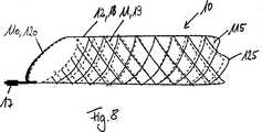
Die punktuelle Verbindung kann im Randbereich, insbesondere am Rand einer Gitterstruktur angeordnet sein. Der Randbereich kann insgesamt die punktuelle Verbindung bilden. Der Randbereich bildet einen in axialer Richtung der Vorrichtung angeordneten Außenbereich, der zumindest außerhalb der ersten Überkreuzung bzw. des ersten Zellsegments der Gitterstruktur angeordnet ist. Der Außenbereich kann bspw. der Schlaufenbereich eines geflochtenen Stents sein. Bei einem wieder einziehbaren Geflecht mit einer schräg zulaufenden Spitze, wie in
Wenn die punktuelle Verbindung am Rand einer Gitterstruktur angeordnet ist, bildet der Rand eine Begrenzung der Verbindung. Die übrigen Seiten der Verbindung grenzen an lose aufeinander angeordnete Gitterstrukturen an. Dabei können beide Gitterstrukturen jeweils am Rand oder eine Gitterstruktur am Rand und die andere Gitterstruktur vom Rand beabstandet, bspw. im mittleren Bereich verbunden sein. Dies gilt sowohl für die erste als auch für die zweite Gitterstruktur.If the point connection is located at the edge of a grid structure, the edge forms a boundary of the connection. The remaining sides of the connection adjoin loosely arranged grid structures. In this case, both lattice structures at the edge or a lattice structure at the edge and the other lattice structure spaced from the edge, for example, be connected in the central region. This applies to both the first and the second lattice structure.
Es ist auch möglich, dass die wenigstens eine punktuelle Verbindung außerhalb der Gitterstruktur angeordnet ist, bspw. durch Verbindungsstränge oder -filamente bzw. - drähte, die über die Gitterstrukturen hinausragen und außerhalb der Gitterstrukturen verbunden sind.It is also possible for the at least one point connection to be arranged outside the lattice structure, for example by connecting strands or filaments or wires which project beyond the lattice structures and are connected outside the lattice structures.
Die punktuelle Verbindung kann unterschiedliche geometrische Formen aufweisen. Bspw. kann die Form der Verbindung der Form einer Zelle oder mehrerer zusammenhängender Zellen entsprechen. Generell kann die punktuelle Verbindung aus einzelnen Unterverbindungen gebildet sein, die ihrerseits punktuelle Verbindungen darstellen, bspw. in der Form von punktuell miteinander verbundenen Einzeldrähten oder Strängen. Die übergeordnete punktuelle Verbindung ist dabei zumindest teilweise von lose aufeinander angeordneten Gitterstrukturen umgeben derart, dass im nicht verbundenen Bereich der Gitterstrukturen eine Relativbewegung der Gitterstrukturen möglich ist. Dies gilt sowohl für flächige als auch für linienförmige punktuelle Verbindungen.The punctiform connection can have different geometric shapes. For example. For example, the shape of the compound may correspond to the shape of a cell or multiple contiguous cells. In general, the punctual connection can be formed from individual sub-connections, which in turn represent punctual connections, for example in the form of selectively connected individual wires or strands. The superordinate point-to-point connection is at least partially surrounded by loosely arranged grating structures such that a relative movement of the grating structures is possible in the non-connected area of the grating structures. This applies to both flat and linear point connections.
Die linienförmige Verbindung kann sich in Umfangsrichtung und/oder in Längsrichtung und/oder schräg zur Längsachse der Vorrichtung erstrecken. Die Erstreckung nur in Umfangsrichtung oder nur in Längsrichtung ist bevorzugt. The linear connection may extend in the circumferential direction and / or in the longitudinal direction and / or obliquely to the longitudinal axis of the device. The extent only in the circumferential direction or only in the longitudinal direction is preferred.
Die Länge der linienförmigen Verbindung beträgt höchstens 30%, insbesondere höchstens 25%, insbesondere höchstens 20%, insbesondere höchstens 15%, insbesondere höchstens 10%, insbesondere höchstens 5%, insbesondere höchstens 4%, insbesondere höchstens 3%, insbesondere höchstens 2%, insbesondere höchstens 1% der Gesamtlänge der Vorrichtung in Längsrichtung oder des Umfangs der Vorrichtung.The length of the linear connection is at most 30%, in particular at most 25%, in particular at most 20%, in particular at most 15%, in particular at most 10%, in particular at most 5%, in particular at most 4%, in particular at most 3%, in particular at most 2%, in particular at most 1% of the total length of the device in the longitudinal direction or the circumference of the device.
Es ist möglich, dass die punktuelle Verbindung am Rand oder sogar außerhalb der beiden Gitterstrukturen angeordnet ist. Bspw. können die beiden Gitterstrukturen durch einen gemeinsamen Strang oder Führungsdraht verbunden sein, durch den die Vorrichtung betätigbar bzw. in einem Zuführsystem bewegbar ist. In diesem Fall sind die beiden Gitterstrukturen über die gesamte Fläche der Vorrichtung lose aufeinander angeordnet und nur am axialen Ende, wo die beiden Gitterstrukturen mit dem Strang bzw. dem Führungsdraht verbunden sind punktuell fixiert.It is possible that the punctual connection is arranged at the edge or even outside the two lattice structures. For example. For example, the two grid structures can be connected by a common strand or guide wire, by means of which the device can be actuated or moved in a feed system. In this case, the two lattice structures over the entire surface of the device are arranged loosely on each other and selectively fixed only at the axial end, where the two lattice structures are connected to the strand or the guide wire.
Die beiden Schichten bzw. Gitterstrukturen sind koaxial ineinander angeordnet. Dadurch wird erreicht, dass der rohrförmige Körper in einem komprimierten Zustand einen gegenüber dem Stand der Technik kleineren Querschnittsdurchmesser aufweist. Konkret erfolgt bei der Erfindung eine regelmäßige Anordnung der einzelnen Drähte bzw. Stege der Gitterstruktur, wodurch die Anzahl an ungenutzten Freiräumen zwischen den einzelnen Drähten bzw. Stegen reduziert ist. Die Crimpbarkeit bzw. Komprimierbarkeit des rohrförmigen Körpers wird somit erhöht.The two layers or grid structures are coaxially arranged one inside the other. It is thereby achieved that the tubular body in a compressed state has a smaller cross-section diameter than the prior art. Specifically, in the invention, a regular arrangement of the individual wires or webs of the grid structure, whereby the number of unused spaces between the individual wires or webs is reduced. The crimpability or compressibility of the tubular body is thus increased.
Durch die doppelwandige Struktur bzw. den mehrschichtigen Aufbau der Umfangswandung aus zueinander beweglichen Schichten können unterschiedliche Einsatzmöglichkeiten abgedeckt werden. Dabei kann bei der erfindungsgemäßen Vorrichtung eine Funktionstrennung erfolgen, wobei eine der Gitterstrukturen beispielsweise eine tragende bzw. stützende Funktion und die andere bzw. eine weitere Gitterstruktur die Funktion der Strömungsbeeinflussung im Bereich eines Aneurysmas aufweist.Due to the double-walled structure or the multilayer structure of the peripheral wall of mutually movable layers different applications can be covered. In this case, in the device according to the invention, a function separation can take place, one of the lattice structures, for example, having a supporting or supporting function and the other or a further lattice structure having the function of influencing the flow in the region of an aneurysm.
Die Gitterstrukturen bzw. separaten Schichten sind punktuell miteinander verbunden. Durch die punktuelle Verbindung zwischen den Gitterstrukturen ist gewährleistet, dass die Gitterstrukturen relativ zueinander im Wesentlichen ihre Position beibehalten. Insbesondere behalten die Gitterstrukturen ihre Relativposition unabhängig von einem komprimierten oder expandierten Zustand bei. Dabei können sich Teile bzw. Abschnitte der Gitterstrukturen relativ zueinander bewegen. Eine vollständige Verschiebung der beiden Gitterstrukturen zueinander wird jedoch durch die punktuelle Verbindung verhindert. Auf diese Weise wird das Risiko einer Dislokation der medizinischen Vorrichtung vermindert.The grid structures or separate layers are selectively connected to each other. The selective connection between the grid structures ensures that the grid structures maintain their position substantially relative to one another. In particular, the grating structures maintain their relative position independent of a compressed or expanded state. In this case, parts or sections of the grid structures can move relative to each other. A complete displacement of the two lattice structures to each other, however, is prevented by the punctiform connection. In this way, the risk of dislocation of the medical device is reduced.
Bei einer bevorzugten Ausführungsform der erfindungsgemäßen medizinischen Vorrichtung ist die erste Gitterstruktur und/oder die zweite Gitterstruktur jeweils aus miteinander verflochtenen Drähten gebildet. Vorzugsweise weisen beide Gitterstrukturen bzw. allgemein die Gitterstrukturen der Umfangswandung jeweils ein Drahtgeflecht auf. Die einzelnen Drahtgeflechte bzw. Gitterstrukturen sind also vorteilhaft aus jeweils mehreren Drähten gebildet, die sich spiralförmig um eine Längsachse des rohrförmigen Körpers erstrecken. Dabei sind gegenläufige Drahtspiralen vorgesehen, die miteinander verflochten sind. Die einzelnen Schichten der Umfangswandung sind also durch Drahtgeflechte bzw. miteinander verflochtene Drähte oder Bänder gebildet. Die Verflechtung besteht jedoch ausschließlich innerhalb einer einzelnen Schicht. Untereinander sind die einzelnen Schichten punktuell miteinander verbunden, so dass zwischen den Schichten eine Relativbewegung ermöglicht ist.In a preferred embodiment of the medical device according to the invention, the first grid structure and / or the second grid structure are each formed from interwoven wires. Preferably, both grid structures or generally the grid structures of the peripheral wall each have a wire mesh. The individual wire meshes or lattice structures are therefore advantageously formed from a plurality of wires each, which extend spirally about a longitudinal axis of the tubular body. In this case, counter-rotating wire spirals are provided, which are intertwined with each other. The individual layers of the peripheral wall are thus formed by wire meshes or interwoven wires or bands. However, the intertwining exists only within a single layer. The individual layers are connected to one another at points, so that a relative movement is made possible between the layers.
In diesem Zusammenhang wird darauf hingewiesen, dass im Rahmen der Anmeldung nicht nur Gitterstrukturen offenbart und beansprucht werden, die ein Drahtgeflecht umfassen. Vielmehr umfasst die Erfindung auch Gitterstrukturen, die auf Basis von Gitterstegen gebildet sind. Derartige Gitterstrukturen können beispielsweise durch Laserschneiden oder Gasphasenabscheideverfahren hergestellt sein.In this context, it should be noted that in the context of the application not only grid structures are disclosed and claimed, which include a wire mesh. Rather, the invention also includes grating structures that are formed on the basis of grid bars. Such grating structures can be produced, for example, by laser cutting or gas-phase deposition processes.
Im Rahmen der Erfindung ist ferner vorgesehen, dass jedes einzelne Drahtelement einer Gitterstruktur bzw. einer Schicht eine einzige Stelle umfasst, an der der Draht oder die Drähte mit einem Draht oder mit Drähten einer benachbarten Schicht verbunden ist. Somit wird erreicht, dass zwischen den Schichten eine punktuelle Verbindung besteht.In the context of the invention it is further provided that each individual wire element of a grid structure or a layer comprises a single point at which the wire or the wires is connected to a wire or to wires of an adjacent layer. This ensures that there is a punctual connection between the layers.
Die erste Gitterstruktur kann ein proximales Ende aufweisen, das mit einem proximalen Ende der zweiten Gitterstruktur verbunden ist, so dass jeweils den proximalen Enden gegenüber angeordnete distale Enden der ersten und zweiten Gitterstruktur relativ zueinander bewegbar sind. Diese Ausführungsform geht auf die Idee zurück, die Gitterstrukturen der separaten Schichten an jeweils einem axialen Ende, insbesondere an den proximalen Enden, miteinander zu verbinden. Somit ist die gesamte Gitterstruktur dazwischen bewegbar. Die distalen Enden der ersten und zweiten Gitterstruktur sind hingegen frei angeordnet, so dass sich die distalen Enden der Gitterstruktur relativ zueinander bewegbar sind. Die zumindest abschnittsweise vorgesehene relative Beweglichkeit der Gitterstrukturen zueinander ermöglicht besonders vorteilhaft eine Funktionstrennung. Insbesondere können die erste und zweite Gitterstruktur unterschiedlich geometrisch gestaltet sein, so dass mit der ersten und der zweiten Gitterstruktur jeweils verschiedene Funktionen erfüllbar sind. Die Verbindung der proximalen Enden der Gitterstrukturen miteinander ist besonders vorteilhaft, da der relativ zueinander bewegbare Bereich der Gitterstrukturen vergleichsweise groß ist. Auf diese Weise können unterschiedliche Eigenschaften der Gitterstrukturen miteinander über einen vergleichsweise großen Bereich oder den gesamten Bereich des rohrförmigen Körpers wirksam werden. Alternativ zur Verbindung der proximalen Enden der Gitterstrukturen ist es auch möglich, dass die distalen Enden der ersten und zweiten Gitterstruktur miteinander verbunden sind. Ferner können die erste und die zweite Gitterstruktur in einen mittleren Bereich des rohrförmigen Körpers miteinander punktuell verbunden sein. Durch die freien Enden der Gitterstrukturen am distalen und/oder proximalen Ende der Vorrichtung wird bewirkt, dass die beiden Gitterstrukturen sich unabhängig voneinander bei der Expansion im Gefäß verkürzen können (foreshortening), bspw. wenn die beiden Gitterstrukturen unterschiedliche Flechtwinkel aufweisen.The first grid structure may have a proximal end connected to a proximal end of the second grid structure such that distal ends of the first and second grid structures disposed opposite the proximal ends, respectively, are movable relative to each other. This embodiment is based on the idea of connecting the grid structures of the separate layers to each other at one axial end, in particular at the proximal ends. Thus, the entire grid structure is movable therebetween. The distal ends of the first and second lattice structures, however, are freely arranged, so that the distal ends of the lattice structure are movable relative to each other. The At least sections provided relative mobility of the lattice structures to each other allows particularly advantageous separation of functions. In particular, the first and second lattice structures may be designed differently geometrically, so that in each case different functions can be fulfilled with the first and the second lattice structure. The connection of the proximal ends of the lattice structures with one another is particularly advantageous, since the region of the lattice structures which is movable relative to one another is comparatively large. In this way, different properties of the grid structures can be effective with each other over a comparatively large area or the entire area of the tubular body. As an alternative to connecting the proximal ends of the lattice structures, it is also possible for the distal ends of the first and second lattice structures to be connected to one another. Further, the first and second grid structures may be selectively connected to each other in a middle portion of the tubular body. The free ends of the lattice structures at the distal and / or proximal end of the device cause the two lattice structures to shorten independently during expansion in the vessel (foreshortening), for example when the two lattice structures have different braiding angles.
Allgemein gilt, dass durch die nur punktuelle Verbindung der Gitterstrukturen eine Funktionstrennung der beiden Strukturen ermöglicht wird.In general, it is possible to separate the functions of the two structures by only selectively connecting the grating structures.
Gemäß einer weiteren bevorzugten Ausführungsform weisen die erste Gitterstruktur und die zweite Gitterstruktur in einem Herstellzustand zumindest abschnittsweise gleiche oder voneinander verschiedene Flechtwinkel auf. Durch unterschiedliche Flechtwinkel zwischen der ersten Gitterstruktur und der zweiten Gitterstruktur bzw. zwischen den separaten Schichten des rohrförmigen Körpers wird erreicht, dass sich die Gitterstrukturen bei der Expansion des rohrförmigen Körpers unterschiedlich stark verkürzen. Auch bei einer Querschnittsänderung des Körperhohlorgans, in dem die medizinische Vorrichtung eingesetzt ist, verhalten sich die Gitterstrukturen mit unterschiedlichen Flechtwinkel verschieden. Die unterschiedliche Verkürzung der Gitterstrukturen kann vorteilhaft für eine genaue Positionierung der medizinischen Vorrichtung eingesetzt werden. Beispielsweise kann die zweite Gitterstruktur derart ausgebildet sein, dass der Effekt des Foreshortening reduziert ist. Die zweite Gitterstruktur kann somit relativ exakt positioniert werden. Da die erste Gitterstruktur punktuell mit der zweiten Gitterstruktur verbunden ist, ermöglicht eine genaue Positionierung der zweiten Gitterstruktur gleichzeitig eine relativ genaue Positionierung der ersten Gitterstruktur bzw. allgemein des rohrförmigen Körpers.According to a further preferred embodiment, the first lattice structure and the second lattice structure have, in a production state, identical or different braiding angles, at least in sections. Due to different braiding angles between the first lattice structure and the second lattice structure or between the separate layers of the tubular body, it is achieved that the lattice structures shorten to different extents during the expansion of the tubular body. Even with a change in cross section of the hollow body of the body in which the medical device is used, the lattice structures with different braiding angles behave differently. The different shortening of the grating structures can be advantageously used for an accurate positioning of the medical device. For example, the second lattice structure may be formed such that the effect of foreshortening is reduced. The second grid structure can thus be positioned relatively accurately. Since the first grid structure is selectively connected to the second grid structure, accurate positioning of the second grid structure simultaneously enables relatively accurate positioning of the first grid structure or, more generally, of the tubular body.
Vorzugsweise beträgt der Flechtwinkel der ersten Gitterstruktur und/oder der zweiten Gitterstruktur höchsten 70°, insbesondere höchstens 65°, insbesondere höchstens 60°, insbesondere höchstens 59°, insbesondere höchstens 57°, insbesondere höchstens 55°, insbesondere höchstens 52°, insbesondere höchstens 50°. Ein derartiger Flechtwinkel stellt sicher, dass einerseits eine ausreichende Flexibilität der Gitterstrukturen bereitgestellt wird. Andererseits bewirkt ein derartiger Flechtwinkel eine Begrenzung des Foreshortening-Effekts. Ferner wird die Stauchbarkeit verringert, so dass der vorbestimmte Durchflusswiderstand nicht beeinträchtigt wird.The braiding angle of the first grid structure and / or the second grid structure is preferably at most 70 °, in particular at most 65 °, in particular at most 60 °, in particular at most 59 °, in particular at most 57 °, in particular at most 55 °, in particular at most 52 °, in particular at most 50 °. Such a braid angle ensures that, on the one hand, sufficient flexibility of the grid structures is provided. On the other hand, such a braid angle causes a limitation of the foreshortening effect. Further, the compressibility is reduced so that the predetermined flow resistance is not impaired.
Zwischen der ersten Gitterstruktur und der zweiten Gitterstruktur kann in einem radial expandierten Zustand des rohrförmigen Körpers zumindest abschnittsweise ein Spalt ausgebildet sein. Insbesondere in Verbindung mit unterschiedlichen Flechtwinkeln für die erste Gitterstruktur und die zweite Gitterstruktur wird ermöglicht, dass sich bei einer Querschnitts- oder Längenänderung des Körperhohlorgans, in dem die medizinische Vorrichtung angeordnet ist, die beiden Gitterstrukturen voneinander abheben. Dadurch wird zwischen den Gitterstrukturen ein Spalt, insbesondere Ringspalt gebildet.Between the first grid structure and the second grid structure, a gap may be formed at least in sections in a radially expanded state of the tubular body. In particular in connection with different braiding angles for the first grid structure and the second grid structure, the two grid structures are made to stand out from one another in the case of a cross-sectional or length change of the body hollow organ in which the medical device is arranged. As a result, a gap, in particular an annular gap, is formed between the grid structures.
Bspw. kann der Spalt dadurch erzeugt werden, dass die äußere, zweite Gitterstruktur bzw. das außen angeordnete Netz in Längsrichtung zwei voneinander beabstandete punktuelle Verbindungen mit der inneren Gitterstruktur aufweist, bspw. zwei in Umfangsrichtung verlaufende Verbindungslinien oder einzelne Verbindungspunkte entlang zweier in Umfangsrichtung verlaufender Linien. Die Verbindungslinien können an den axialen Enden der Gitterstruktur oder von einem oder beiden Enden axial nach innen versetzt angeordnet sein. Die beiden Gitterstrukturen weisen unterschiedliche Flechtwinkel auf. Die äußeren zweite Gitterstruktur weist einen kleineren Flechtwinkel und somit eine geringeres Foreshortening als die innere erste Gitterstruktur auf. Im expandierten Zustand ist die innere Gitterstruktur stärker verkürzt als die äußere Gitterstruktur. Dadurch kommt es zu einer Auswölbung der zweiten Gitterstruktur und somit zu einem Spalt zwischen beiden Gitterstrukturen. Der Flechtwinkelunterschied kann mindestens 1°, insbesondere mindestens 2°, mindestens 3°, mindestens 4°, mindestens 5°, mindestens 10°, mindestens 15°, mindestens 20°, mindestens 25°, mindestens 30° betragen. Die Obergrenze für den Bereich des Flechtwinkelunterschieds beträgt höchstens 30°, insbesondere höchstens 25°, höchstens 20°, höchstens 15°, höchstens 10°, höchstens 5°, höchstens 4°, höchstens 3°, höchstens 2°, höchstens 1°. Die vorstehend genannten Ober- und Untergrenzen können jeweils miteinander kombiniert werden.For example. For example, the gap may be formed by having the outer, second grid structure or network arranged longitudinally two spaced-apart connections with the inner grid structure, for example two circumferentially extending connection lines or individual connection points along two circumferentially extending lines. The connecting lines may be arranged offset axially inwardly at the axial ends of the grid structure or from one or both ends. The two lattice structures have different braiding angles. The outer second lattice structure has a smaller braiding angle and thus a lower foreshortening than the inner first lattice structure. In the expanded state, the inner lattice structure is shorter than the outer lattice structure. This results in a bulge of the second lattice structure and thus to a gap between the two lattice structures. The braid angle difference may be at least 1 °, in particular at least 2 °, at least 3 °, at least 4 °, at least 5 °, at least 10 °, at least 15 °, at least 20 °, at least 25 °, at least 30 °. The upper limit for the range of the braid angle difference is at most 30 °, more preferably at most 25 °, at most 20 °, at most 15 °, at most 10 °, at most 5 °, at most 4 °, at most 3 °, at most 2 °, at most 1 °. The above upper and lower limits can each be combined with each other.
Generell kann die Auswölbung zwischen einzelnen axial beabstandeten Verbindungspunkten, insbesondere zwischen Paaren von axial beabstandeten Verbindungspunkten erfolgen. Es können zwei in Längsrichtung beabstandete Verbindungslinien aus mehreren in Umfangsrichtung in Reihe angeordneten Verbindungspunkten vorgesehen sein. Es können auch mehr als zwei derartige Verbindungslinien vorgesehen sein, zwischen denen jeweils eine Auswölbung gebildet ist, so dass mehrere Auswölbungen hintereinander angeordnet sind. In general, the bulge between individual axially spaced connection points, in particular between pairs of axially spaced connection points. There may be provided two longitudinally spaced connecting lines of a plurality of circumferentially arranged in series connection points. It is also possible for more than two such connecting lines to be provided, between each of which a bulge is formed, so that a plurality of bulges are arranged one behind the other.
Im Spalt zwischen den Gitterstrukturen entstehen Strömungswirbel, die eine Art Polster bilden. Das Polster führt zu einem erwünschten Energieverlust, wobei sich die Strömungsgeschwindigkeit verlangsamt. Die Schubspannungen im Hauptgefäß wirken somit zunächst im Spalt und erzeugen dort die Wirbel. Die über die Wandung des Netzes bzw. der äußeren Gitterstruktur vom Spalt ins Aneurysma übertragenen Schubspannungen werden dadurch verringert. Die Gerinnung im Aneurysma wird begünstigt. Ferner werden die durch das Einströmen des Blutes in das Aneurysma bewirkten lokalen Druckbeanspruchungen der Aneurysmenwand reduziert.In the gap between the lattice structures arise flow vortexes, which form a kind of cushion. The pad leads to a desired energy loss, slowing down the flow rate. The shear stresses in the main vessel thus initially act in the gap and generate the vortex there. The shear stresses transmitted via the wall of the network or the outer lattice structure from the gap into the aneurysm are thereby reduced. The coagulation in the aneurysm is favored. Furthermore, the local pressure stresses of the aneurysm wall caused by the inflow of the blood into the aneurysm are reduced.
Vorzugsweise weisen die erste Gitterstruktur und die zweite Gitterstruktur jeweils geschlossene Maschen auf. Die Größe der Maschen der ersten Gitterstruktur ist vorteilhafterweise von der Größe der Maschen der zweiten Gitterstruktur verschieden. Insbesondere kann die erste Gitterstruktur eine kleinere Maschengröße aufweisen als die zweite Gitterstruktur. Mit anderen Worten weist die erste Gitterstruktur vorzugsweise eine gegenüber der zweiten Gitterstruktur erhöhte Feinmaschigkeit auf. Die zweite Gitterstruktur kann beispielsweise eine Tragstruktur für die netzartige Struktur der ersten Gitterstruktur bilden. Auf diese Weise wird die Funktionstrennung zwischen den beiden Gitterstrukturen bzw. Schichten der Umfangswandung sichergestellt. Die zweite Gitterstruktur stützt bzw. fixiert die erste Gitterstruktur im Blutgefäß. Die erste Gitterstruktur kann hingegen derart feinmaschig ausgebildet sein, dass eine effiziente Strömungsbeeinflussung der Blutströmung in das Aneurysma gewährleistet ist. Ferner kann die erste Gitterstruktur derart flexibel sein, dass die erste Gitterstruktur einer Querschnittsänderung des Blutgefäßes gut folgen kann.Preferably, the first grid structure and the second grid structure each have closed meshes. The size of the meshes of the first lattice structure is advantageously different from the size of the meshes of the second lattice structure. In particular, the first grid structure may have a smaller mesh size than the second grid structure. In other words, the first lattice structure preferably has an increased fineness compared to the second lattice structure. The second lattice structure may for example form a support structure for the net-like structure of the first lattice structure. In this way, the separation of functions between the two lattice structures or layers of the peripheral wall is ensured. The second lattice structure supports or fixes the first lattice structure in the blood vessel. On the other hand, the first lattice structure may be designed in such a fine mesh that an efficient flow influencing of the blood flow into the aneurysm is ensured. Furthermore, the first lattice structure can be so flexible that the first lattice structure can easily follow a change in the cross-section of the blood vessel.
Die Drähte der ersten Gitterstruktur weisen vorzugsweise einen kleineren Querschnittsdurchmesser als die Drähte der zweiten Gitterstruktur auf. Die Ausweitbarkeit der ersten Gitterstruktur gegenüber der zweiten Gitterstruktur wird somit erhöht. Die erste Gitterstruktur kann ferner eine größere Anzahl an Drähten aufweisen als die zweite Gitterstruktur. Damit ist sichergestellt, dass die erste Gitterstruktur eine höhere Feinmaschigkeit aufweist als die zweite Gitterstruktur. Im Zusammenhang mit einem kleineren Querschnittsdurchmesser der Drähte der ersten Gitterstruktur wird die Ausweitbarkeit der ersten Gitterstruktur gegenüber der zweiten Gitterstruktur weiter erhöht. Die Funktion der Strömungsbeeinflussung einer Blutströmung in das Aneurysma wird verbessert.The wires of the first grid structure preferably have a smaller cross-sectional diameter than the wires of the second grid structure. The expandability of the first grid structure with respect to the second grid structure is thus increased. The first grid structure may further comprise a larger number of wires than the second grid structure. This ensures that the first lattice structure has a higher fine mesh than the second lattice structure. In connection with a smaller cross-sectional diameter of the wires of the first grid structure, the expandability of the first grid structure with respect to the second grid structure is further increased. The function of influencing the flow of blood into the aneurysm is improved.
Vorzugsweise bildet die erste Gitterstruktur eine Außenschicht und die zweite Gitterstruktur eine Innenschicht des rohrförmigen Körpers. Dabei kann die zweite Gitterstruktur eine Tragstruktur und die erste Gitterstruktur eine netzartige Abdeckstruktur bilden. Die Tragstruktur stützt die Abdeckstruktur von Innen. Dadurch wird vermieden, dass sich die erste Gitterstruktur bzw. die Abdeckstruktur nicht vollständig bei der Expansion entfaltet. Die innere Tragstruktur bzw. die die Innenschicht bildende zweite Gitterstruktur stützt die erste Gitterstruktur über ihre gesamte Länge.Preferably, the first grid structure forms an outer layer and the second grid structure forms an inner layer of the tubular body. In this case, the second lattice structure may form a support structure and the first lattice structure may form a net-like cover structure. The support structure supports the cover structure from the inside. This avoids that the first lattice structure or the cover structure does not fully unfold during the expansion. The inner support structure or the second lattice structure forming the inner layer supports the first lattice structure over its entire length.
Bei einer weiteren bevorzugten Ausgestaltung der medizinischen Vorrichtung weist die erste Gitterstruktur eine axiale Längserstreckung auf, die kleiner als eine axiale Längserstreckung der zweiten Gitterstruktur ist, so dass die erste Gitterstruktur die zweite Gitterstruktur abschnittsweise, insbesondere um höchstens 98%, höchstens 97%, höchstens 96%, höchstens 95%, höchstens 94%, höchstens 93%, höchstens 92%, höchstens 91%, höchstens 90%, höchstens 85%, höchstens 80%, höchstens 75%, höchstens 70%, höchstens 65%, höchstens 60%, höchstens 55%, höchstens 50%, höchstens 45%, höchstens 40%, höchstens 35%, höchstens 30%, höchstens 25%, höchstens 20%, höchstens 15%, höchstens 10%, höchstens 5% bezogen auf die längere Gitterstruktur überdeckt.In a further preferred embodiment of the medical device, the first lattice structure has an axial longitudinal extent which is smaller than an axial longitudinal extent of the second lattice structure, such that the first lattice structure sections the second lattice structure in sections, in particular by at most 98%, at most 97%, at most 96 %, maximum 95%, maximum 94%, maximum 93%, maximum 92%, maximum 91%, maximum 90%, maximum 85%, maximum 80%, maximum 75%, maximum 70%, maximum 65%, maximum 60%, not more than 55%, not more than 50%, not more than 45%, not more than 40%, not more than 35%, not more than 30%, not more than 25%, not more than 20%, not more than 15%, not more than 10%, not more than 5% covered by the longer lattice structure.
Die vorgenannten geometrischen Verhältnisse gelten für den Herstellzustand der medizinischen Vorrichtung. Der Herstellzustand entspricht im Wesentlichen einem kraftunbelasteten Zustand. Das bedeutet, dass die medizinische Vorrichtung keiner äußeren Kraft ausgesetzt ist, die eine Komprimierung des rohrförmigen Körpers bewirkt. Mit anderen Worten ist der rohrförmigen Körper im Herstellzustand vollständig expandiert.The aforementioned geometric conditions apply to the manufacturing state of the medical device. The manufacturing state essentially corresponds to a force-unloaded state. This means that the medical device is not exposed to external force that causes compression of the tubular body. In other words, the tubular body is completely expanded in the manufacturing state.
Es ist auch möglich, die Vorrichtung so anzupassen, dass die vorgenannten geometrischen Verhältnisse im komprimierten Zustand vorliegen, wobei die erste Gitterstruktur kürzer als die zweite Gitterstruktur ist. Die vorstehend genannten Werte werden auch im Zusammenhang mit dem komprimierten Zustand offenbart.It is also possible to adapt the device so that the aforementioned geometric conditions are in the compressed state, the first lattice structure being shorter than the second lattice structure. The above values are also disclosed in the context of the compressed state.
Der Längenunterschied zwischen den beiden Gitterstrukturen kann durch eine Anpassung des Foreshortenings durch eine geeignete Wahl der Flechtwinkel beim Expandieren vergrößert, verkleinert oder konstant gehalten werden. Bspw. kann der Längenunterschied um wenigstens 10%, insbesondere wenigstens 20%, insbesondere wenigstens 30%, insbesondere wenigstens 40%, insbesondere wenigstens 50%, insbesondere wenigstens 60%, insbesondere wenigstens 70%, insbesondere wenigstens 80%, insbesondere wenigstens 90% oder um 100% (Längenausgleich) verkürzt werden. Andererseits kann der Längenunterschied um wenigstens 2%, insbesondere wenigstens 5%, insbesondere wenigstens 10%, insbesondere wenigstens 20%, insbesondere wenigstens 30%, insbesondere wenigstens 40%, insbesondere wenigstens 50%, insbesondere wenigstens 60% vergrößert werden. Bei Längengleichheit, also wenn der Ausgangsunterschied 0 mm beträgt, werden die vorstehend genannten Werte auf die Gesamtlänge einer der beiden Gitterstrukturen bezogen.The length difference between the two lattice structures can be increased, reduced or adjusted by an adaptation of the foreshortening by a suitable choice of braiding angles during expansion kept constant. For example. the difference in length may be at least 10%, in particular at least 20%, in particular at least 30%, in particular at least 40%, in particular at least 50%, in particular at least 60%, in particular at least 70%, in particular at least 80%, in particular at least 90% or at 100 % (Length compensation) can be shortened. On the other hand, the difference in length can be increased by at least 2%, in particular at least 5%, in particular at least 10%, in particular at least 20%, in particular at least 30%, in particular at least 40%, in particular at least 50%, in particular at least 60%. In the case of length equality, ie if the starting difference is 0 mm, the abovementioned values are related to the total length of one of the two lattice structures.
In absoluten Werten kann der Längenunterschied wie folgt geändert (verringert oder vergrößert) werden: 1 mm, 5 mm, 10 mm, 15 mm, 20 mm. Im Fall der Verringerung des Längenunterschieds sind diese Werte untere Bereichsgrenzen (wenigstens) und im Fall der Vergrößerung obere Bereichsgrenzen (höchstens).In absolute terms, the difference in length can be changed (reduced or increased) as follows: 1 mm, 5 mm, 10 mm, 15 mm, 20 mm. In the case of decreasing the difference in length, these values are lower range limits (at least) and in case of enlargement upper range limits (at most).
Vorzugsweise ist die zweite Gitterstruktur zumindest abschnittsweise durch die erste Gitterstruktur bedeckt. Der rohrförmige Körper weist also zumindest einen Abschnitt auf, der einen mehrschichtigen Aufbau aufweist.Preferably, the second grid structure is at least partially covered by the first grid structure. The tubular body thus has at least one section which has a multilayer construction.
Der rohrförmige Körper kann wenigstens eine dritte Gitterstruktur aufweisen. Die dritte Gitterstruktur bildet vorzugsweise gemeinsam mit der ersten Gitterstruktur die Außenschicht des rohrförmigen Körpers bzw. der Umfangswandung des rohrförmigen Körpers. Im Allgemeinen können die einzelnen separaten Schichten der Umfangswandung mehrere Gitterstrukturen aufweisen. Die Gitterstrukturen einzelner Schichten können relativ zueinander bewegbar sein. Wesentlich ist, dass eigenständige Schichten jeweils wenigstens eine Gitterstruktur umfassen, die gegenüber einer Gitterstruktur einer benachbarten Schicht abschnittsweise relativbeweglich ist. Bevorzugt ist es, wenn die Außenschicht mehrere Gitterstrukturen aufweist. Im komprimierten und/oder expandierten Zustand des rohrförmigen Körpers können die Gitterstrukturen der Außenschicht, also die erste und die dritte Gitterstruktur zueinander fluchtend angeordnet sein. Der Querschnittsdurchmesser des rohförmigen Körpers im komprimierten Zustand ist somit reduziert. Alternativ können die Gitterstrukturen der Außensicht, also die erste und die dritte Gitterstruktur, im komprimierten und/oder expandierten Zustand des rohrförmigen Körpers überlappend angeordnet sein. Das ermöglicht eine vergleichsweise großflächige Abdeckung der zweiten Gitterstruktur in einem expandierten Zustand des rohrförmigen Körpers.The tubular body may have at least a third lattice structure. The third grid structure preferably forms, together with the first grid structure, the outer layer of the tubular body or of the circumferential wall of the tubular body. In general, the individual separate layers of the peripheral wall may have a plurality of grid structures. The lattice structures of individual layers can be movable relative to one another. It is essential that independent layers each comprise at least one lattice structure which is movable relative to a lattice structure of an adjacent layer in sections. It is preferred if the outer layer has a plurality of lattice structures. In the compressed and / or expanded state of the tubular body, the lattice structures of the outer layer, that is, the first and the third lattice structure may be arranged in alignment with one another. The cross-sectional diameter of the green body in the compressed state is thus reduced. Alternatively, the grid structures of the external view, so the first and the third grid structure, may be arranged overlapping in the compressed and / or expanded state of the tubular body. This allows a relatively large area coverage of the second grid structure in an expanded state of the tubular body.
Vorzugsweise ist die erste Gitterstruktur an einem proximalen Ende und die dritte Gitterstruktur an einem distalen Ende mit der zweiten Gitterstruktur verbunden, die die Innenschicht des rohrförmigen Körpers bildet. Mit anderen Worten weisen die erste und die dritte Gitterstruktur jeweils ein an der zweiten Gitterstruktur fixiertes Ende und ein freies Ende auf, wobei die freien Enden der ersten und der dritten Gitterstruktur einander zugewandt bzw. benachbart angeordnet sind. Im komprimierten Zustand des rohrförmigen Körpers können die freien Enden der ersten und dritten Gitterstruktur fluchtend zueinander bzw. bündig aneinander angeordnet sein. Die freien Enden der ersten und dritten Gitterstruktur können sich auch im komprimierten Zustand des rohrförmigen Körpers überlappen.Preferably, the first grid structure is connected at a proximal end and the third grid structure is connected at a distal end to the second grid structure forming the inner layer of the tubular body. In other words, the first and third lattice structures each have an end fixed to the second lattice structure and a free end, with the free ends of the first and third lattice structures facing each other. In the compressed state of the tubular body, the free ends of the first and third lattice structure can be arranged flush with each other or flush with each other. The free ends of the first and third grid structures may also overlap in the compressed state of the tubular body.
Bevorzugt ist vorgesehen, dass sich die erste Gitterstruktur und die dritte Gitterstruktur in einen radial komprimierten Zustand oder einen radial expandierten Zustand zumindest abschnittsweise überlappen. Aufgrund des Foreshortening-Effekts, der nicht nur auf die erste und dritte Gitterstruktur, sondern insbesondere auf die zweite Gitterstruktur wirkt, die die Innenschicht des rohrförmigen Körpers bildet, erfolgt bei der Expansion des rohrförmigen Körpers eine Verkürzung der Innenschicht bzw. zweiten Gitterstruktur. Die beiden Gitterstrukturen, die die Außenschicht bilden, also die erste und dritte Gitterstruktur, nähern sich bei der Expansion des rohrförmigen Körpers einander an. Durch geeignet Auslegung der einzelnen Gitterstrukturen kann erreicht werden, dass sich die erste und dritte Gitterstruktur im expandierte Zustand des rohrförmigen Körpers abschnittsweise überlappen. Bei der Expansion nähern sich also die freien Enden der ersten und zweiten Gitterstuktur an und schieben sich übereinander. Dies ist der Fall, wenn der Effekt des Foreshortenings der äußeren Gitterstruktur kleiner ist als der Effekt des Foreshortenings der inneren Gitterstruktur. Vorzugsweise ist der überlappende Bereich der ersten und dritten Gitterstruktur am Behandlungsort im Bereich des Aneurysmas angeordnet. Dadurch wird bewirkt, dass die Außenschicht des rohrförmigen Körpers im Bereich des Aneurysmas eine erhöhte Ausweitbarkeit aufweist, da die freien Enden der ersten und dritten Gitterstruktur relativ zueinander bewegbar sind. Unter Einfluss der Blutströmung können sich daher die freien Enden der ersten und dritten Gitterstruktur bzw. der Überlappungsbereiche in das Aneurysma wölben, so dass zwischen der Außenschicht und der Innenschicht bzw. der zweiten Gitterstruktur im Bereich des Aneurysmas ein Strömungspolster gebildet ist, in dem die Strömungsenergie des in das Aneurysma strömenden Blutes reduziert wird und somit die Belastung auf die Aneurysmenwand gemindet wird. Es ist ferner möglich, dass sich die erste und dritte Gitterstruktur sowohl im radial komprimierten Zustand, als auch im radial expandierten Zustand abschnittsweise überlappen. Die Gitterstrukturen bzw. die Innenschicht und die Außenschicht können derart ausgebildet sein, dass sich die erste und dritte Gitterstruktur im radial expandierten Zustand des rohrförmigen Körpers nicht überlappen. Mit anderen Worten können die freien Ende der ersten und dritten Gitterstruktur im radial expandierten Zustand bündig aneinander oder beabstandet voneinander angeordnet sein. Die erste und dritter Gitterstruktur können also im radial expandierten Zustand des rohrförmigen Körpers zueinander fluchtend angeordnet sein.It is preferably provided that the first grid structure and the third grid structure at least partially overlap in a radially compressed state or a radially expanded state. Due to the foreshortening effect, which acts not only on the first and third lattice structures, but in particular on the second lattice structure that forms the inner layer of the tubular body, a shortening of the inner layer or second lattice structure takes place during the expansion of the tubular body. The two lattice structures forming the outer layer, that is, the first and third lattice structures, approach each other as the tubular body expands. By suitably designing the individual lattice structures, it can be achieved that the first and third lattice structures overlap in sections in the expanded state of the tubular body. During expansion, therefore, approach the free ends of the first and second grid structure and slide over each other. This is the case when the effect of foreshortening the outer lattice structure is smaller than the effect of foreshortening the inner lattice structure. Preferably, the overlapping region of the first and third lattice structures is arranged at the treatment site in the region of the aneurysm. This causes the outer layer of the tubular body in the region of the aneurysm has an increased expandability, since the free ends of the first and third lattice structure are movable relative to each other. Under the influence of the blood flow, therefore, the free ends of the first and third lattice structures or the overlapping regions can bulge into the aneurysm, so that a flow cushion is formed between the outer layer and the inner layer or the second lattice structure in the region of the aneurysm in which the flow energy of the blood flowing into the aneurysm is reduced and thus the burden on the aneurysm wall is diminished. It is also possible that the first and third Lattice structure overlap in sections both in the radially compressed state, as well as in the radially expanded state. The grid structures or the inner layer and the outer layer may be formed such that the first and third grid structures do not overlap in the radially expanded state of the tubular body. In other words, the free ends of the first and third grid structures in the radially expanded state can be arranged flush with each other or spaced from each other. The first and third grid structures can therefore be arranged in alignment with one another in the radially expanded state of the tubular body.
Bei einer weiteren bevorzugten Ausführungsform ist vorgesehen, dass die erste Gitterstruktur und die dritte Gitterstruktur jeweils ein proximales Ende umfassen, das mit der zweiten Gitterstruktur verbunden ist. Dabei kann das proximale Ende der ersten Gitterstruktur von dem proximalen Ende der zweiten Gitterstruktur beabstandet angeordnet sein. Die Außenschicht kann im Allgemeinen mehrere Gitterstrukturen aufweisen, die jeweils einen axialen Abschnitt der Außenschicht bilden. Die Gitterstrukturen, insbesondere die erste und die dritte Gitterstruktur weisen jeweils ein proximales Ende auf, das mit der zweiten Gitterstruktur, also der Innenschicht, punktuell verbunden ist. Das distale Ende der ersten und dritten Gitterstruktur ist frei angeordnet. Die erste und dritte Gitterstruktur können sich überlappen. Auf diese Weise können die erste und dritte Gitterstruktur eine schuppenartige Außenschicht bilden. Insbesondere können die erste und dritte Gitterstruktur eine Klappenfunktion aufweisen, wobei die erste und dritte Gitterstruktur vorteilhaft im Bereich eines Aneurysmas positioniert werden. Die freien Enden der ersten und/oder dritten Gitterstruktur können bezüglich der Innenschicht des rohrförmigen Körpers radial nach außen auslenkbar sein, so dass ein Katheter, beispielsweise ein Katheter zur Positionierung von Coils, in das Aneurysma einführbar ist, wobei der Katheter durch die Maschen der zweiten Gitterstruktur hindurchgeführt wird und wenigstens ein freies Ende der ersten oder dritten Gitterstruktur radial nach außen auslenkt, um einen Zugang zum Aneurysma zu erhalten.In a further preferred embodiment, it is provided that the first grid structure and the third grid structure each comprise a proximal end which is connected to the second grid structure. In this case, the proximal end of the first lattice structure can be arranged at a distance from the proximal end of the second lattice structure. The outer layer may generally include a plurality of lattice structures, each forming an axial portion of the outer layer. The lattice structures, in particular the first and the third lattice structure, each have a proximal end which is selectively connected to the second lattice structure, that is to say the inner layer. The distal end of the first and third lattice structures is freely arranged. The first and third lattice structures may overlap. In this way, the first and third lattice structures can form a scale-like outer layer. In particular, the first and third lattice structures may have a valve function, wherein the first and third lattice structures are advantageously positioned in the region of an aneurysm. The free ends of the first and / or third lattice structure can be deflected radially outwards with respect to the inner layer of the tubular body, so that a catheter, for example a catheter for positioning coils, can be introduced into the aneurysm, wherein the catheter passes through the meshes of the second Lattice structure is passed and deflects at least one free end of the first or third grid structure radially outward in order to obtain access to the aneurysm.
Eine weitere bevorzugte Ausgestaltung der medizinischen Vorrichtung sieht vor, dass die erste Gitterstruktur einen mittleren Abschnitt und zwei dem mittleren Abschnitt begrenzende Randabschnitte umfasst. Im mittleren Abschnitt weist die erste Gitterstruktur einen kleineren Flechtwinkel als in den Randabschnitten auf. Im Allgemeinen kann vorgesehen sein, dass der Flechtwinkel der jeweiligen Gitterstruktur variabel ist. Mit anderen Worten kann sich der Flechtwinkel entlang der Gitterstruktur, insbesondere in Längsrichtung der Gitterstruktur, ändern. Vorzugsweise ändert sich der Flechtwinkel entlang der ersten Gitterstruktur derart, dass im mittleren Abschnitt ein kleinerer Flechtwinkel vorliegt als in den Randabschnitten. Damit wird erreicht, dass die erste Gitterstruktur im mittleren Abschnitt eine gegenüber den Randabschnitten erhöhte radiale Ausweitbarkeit aufweist. Der mittlere Abschnitt der ersten Gitterstruktur ist also in radialer Richtung weiter ausweitbar als die Randabschnitte. Die Ausweitbarkeit ist eine Folge der lokalen Flexibilität im mittleren Abschnitt. Der Begriff Flexibilität wird jedoch in erster Linie für das Biegeverhalten der gesamten Vorrichtung bzw. des gesamten Stents verwendet.A further preferred embodiment of the medical device provides that the first lattice structure comprises a central portion and two edge portions bounding the middle portion. In the middle section, the first lattice structure has a smaller braiding angle than in the edge sections. In general, it can be provided that the braiding angle of the respective grid structure is variable. In other words, the braiding angle can change along the grid structure, in particular in the longitudinal direction of the grid structure. The braiding angle preferably changes along the first grid structure such that a smaller braiding angle is present in the middle section than in the edge sections. This ensures that the first lattice structure in the central portion has a relative to the edge portions increased radial expandability. The middle section of the first lattice structure can therefore be widened further in the radial direction than the edge sections. The extensibility is a consequence of local flexibility in the middle section. However, the term flexibility is used primarily for the bending behavior of the entire device or of the entire stent.
Eine Streckung des Gefäßabschnitts, in dem die medizinische Vorrichtung eingesetzt ist, während der Systole wird durch die Randabschnitte kompensiert. Somit ist sichergestellt, dass sich die axialen Enden der ersten Gitterstruktur, insbesondere ein freies Ende der ersten Gitterstruktur, ihre Lage zumindest nicht signifikant verändern. Die Positionierung der ersten Gitterstruktur wird vielmehr beibehalten. Der mittlere Abschnitt mit dem kleineren Flechtwinkel kann hingegen während der Systole den kleineren Foreshortening-Effekt nutzen. Konkret kann sich der mittlere Abschnitt der ersten Gitterstruktur bei einer Streckung und gleichzeitigen Ausweitung des Gefäßabschnitts verkürzen. Vorzugsweise ist der mittlere Abschnitt auf Höhe des Aneurysmas bzw. des Aneurysmenhalses positioniert. Damit wird erreicht, dass sich der mittlere Abschnitt der ersten Gitterstruktur während der Systole in das Aneurysma bzw. in den Bereich des Aneurysmenhalses hineinwölben kann. Durch den kleinen Flechtwinkel ist die Längenänderung nicht signifikant. Damit trägt der mittlere Abschnitt der ersten Gitterstruktur dazu bei, den systolischen Druck aus dem Blutgefäß in das Aneurysma zumindest bis zu einem gewissen Grad zu übertragen, so dass weiterhin eine mechanische Belastung der Zellen der Aneurysmenwand gegeben ist. Eine Degeneration der Zellen in der Aneurysmenwand wird somit vermieden.An extension of the vessel portion in which the medical device is inserted during systole is compensated by the edge portions. This ensures that the axial ends of the first lattice structure, in particular a free end of the first lattice structure, at least do not change their position significantly. The positioning of the first grid structure is rather maintained. The middle section with the smaller braiding angle, on the other hand, can use the smaller foreshortening effect during systole. Concretely, the central portion of the first lattice structure can be shortened at a stretch and simultaneous expansion of the vessel portion. Preferably, the middle section is positioned at the level of the aneurysm or aneurysm neck. This ensures that the middle section of the first lattice structure can bulge into the aneurysm or into the region of the aneurysm neck during systole. Due to the small braiding angle, the change in length is not significant. Thus, the central portion of the first lattice structure helps to transmit the systolic pressure from the blood vessel into the aneurysm, at least to some extent, so that there continues to be mechanical stress on the cells of the aneurysmal wall. Degeneration of the cells in the aneurysmal wall is thus avoided.
Gemäß einem nebengeordneten Aspekt beruht die Erfindung auf dem Gedanken, ein System für medizinische Anwendungen mit einer Vorrichtung nach Anspruch 1 und einem Zuführsystem anzugeben, das ein flexibles Zuführelement, insbesondere einen Führungsdraht, umfasst. Das Zuführelement ist mit der Vorrichtung gekoppelt oder koppelbar. Vorzugsweise ist das System derart angepasst, dass die Vorrichtung in das Zuführsystem wieder einziehbar ist.According to a secondary aspect, the invention is based on the idea of providing a system for medical applications with a device according to claim 1 and a delivery system comprising a flexible delivery element, in particular a guide wire. The feed element is coupled or coupleable to the device. Preferably, the system is adapted so that the device is retractable into the delivery system.
Die im Zusammenhang mit der medizinischen Vorrichtung beschriebenen Ausführungsbeispiele und Vorteile gelten gleichermaßen für das System mit einer derartigen Vorrichtung.The embodiments and advantages described in connection with the medical device apply equally to the system with such a device.
Die Erfindung wird im Folgenden anhand von Ausführungsbeispielen unter Bezugnahme auf die beigefügten schematischen Zeichnungen näher erläutert. Darin zeigen:The invention will be described below with reference to exemplary embodiments with reference to FIGS attached schematic drawings explained in more detail. Show:
In
Der Einfluss der Druckschwankungen auf das Aneurysma
Dennoch besteht die Möglichkeit, dass die Druckverminderung eine Degeneration der Zellen der Aneurysmenwand
Ferner wird ein Aneurysma
Herkömmliche Aneurysmenstents
Aus dem Stand der Technik sind herkömmliche Aneurysmenstents
In
Demgegenüber ist bei dem erfindungsgemäßen Ausführungsbeispiel vorgesehen, dass die medizinische Vorrichtung einen rohrförmigen Körper
Durch die separaten Schichten, die jeweils eine Gitterstruktur
Die Drähte
In
Bei dem erfindungsgemäßen Ausführungsbeispiel gemäß
Im Allgemeinen hat es sich als vorteilhaft herausgestellt, wenn eine Schicht
Besonders bevorzugt ist es, wenn die feinmaschige Schicht die Außenschicht
Im Allgemeinen weist die Vorrichtung vorzugsweise einen rohrförmigen Körper
Generell ist es möglich, dass beiden Schichten, also die Außenschicht
Ferner wird darauf hingewiesen, dass die Erfindung nicht auf zweischichtige Strukturen eingeschränkt ist. Vielmehr werden im Rahmen der Anmeldung auch rohrförmige Körper
Nachfolgend werden besondere vorteilhafte Ausführungen des Trägers
Der Träger
The carrier
Generell weist der Träger
Der Träger
Vorzugsweise bildet der Träger
Nachfolgend werden bevorzugte Varianten des Netzes
Vorzugsweise weist das Netz
Preferably, the network has
Vorzugsweise bildet das Netz
Die erste Gitterstruktur
In diesem Zusammenhang wird darauf hingewiesen, dass im Rahmen der Anmeldung proximal angeordnete Elemente näher am Anwender angeordnet sind als distale Elemente.In this connection, it is pointed out that, in the context of the application, proximally arranged elements are arranged closer to the user than distal elements.
Vorzugsweise weisen die erste Gitterstruktur
Vorzugsweise weisen die Gitterstrukturen
Um die erfindungsgemäße Doppelfunktion zu erreichen, nämlich einerseits eine ausreichende Fixierung des rohrförmigen Körpers
Bei herkömmlichen Aneurysmenstents
In
Bei der medizinischen Vorrichtung ist daher vorteilhaft vorgesehen, dass der Flechtwinkel begrenzt ist. Insbesondere hat es sich als zweckmäßig erwiesen, wenn der Flechtwinkel höchstens 70°, insbesondere höchstens 67°, insbesondere höchstens 65°, insbesondere höchstens 63°, insbesondere höchstens 60°, beträgt. Dabei bezieht sich der Flechtwinkel auf den spitzen Winkel, der zwischen einem Draht der Gitterstruktur und der Längsachse des rohrförmigen Körpers
Vorzugsweise ist ein Flechtwinkel für die erste Gitterstruktur
In diesem Zusammenhang wird darauf hingewiesen, dass sich Dimensionsangaben für die medizinische Vorrichtung, insbesondere den rohrförmigen Körper
Die erste Gitterstruktur
In einer bevorzugten Variante ist der Flechtwinkel des Trägers
Außerdem kann das Außenelement, bzw. die äußere Gitterstruktur ein kleineres foreshortening als das Innenelement bzw. die innere Gitterstruktur aufweisen, so dass das Außenelement gut an der Gefäßwand anliegt.In addition, the outer element or the outer lattice structure may have a smaller foreshortening than the inner element or the inner lattice structure, so that the outer element abuts well against the vessel wall.
In
Wenn das Netz in der bevorzugten Ausgestaltung die Außenschicht
Nach vollständiger Expansion des rohrförmigen Körpers
Durch die unterschiedlichen Flechtwinkel zwischen der ersten Gitterstruktur
Vorzugsweise ist das Netz
Die Auslenkung des Netzes
Im Allgemeinen hat sich gezeigt, dass es vorteilhaft ist, eine Gitterstruktur bereitzustellen, die derart flexibel ist, dass sie zumindest abschnittsweise in das Aneurysma
Mit der erfindungsgemäßen Vorrichtung werden beide Effekte erzielt, wobei die Funktionen unterschiedlichen Gitterstrukturen
In
Ein weiteres Ausführungsbeispiel ist in
Ein weiteres Ausführungsbeispiel ist in
Die erste Gitterstruktur
Grundsätzlich ist die Erfindung nicht auf zwei Netze
In
Bei dem Ausführungsbeispiel gemäß
Gleichzeitig ermöglicht die Beweglichkeit der freien Enden der ersten und dritten Gitterstruktur
Die fluchtende Anordnung der Netze
Bei dem Ausführungsbeispiel gemäß
Im expandierten bzw. implantierten Zustand des rohrförmigen Körpers
Wie zuvor bereits beschrieben, ermöglicht die Einstellung unterschiedlicher Flechtwinkel in separaten Schichten
Ein Ausführungsbeispiel eines Gesamtsystems bzw. einer Vorrichtung mit Träger
Dieser Aufbau des proximalen Endes der Vorrichtung gilt für alle Ausführungsbeispiele dieser Anmeldung, bei dem die Vorrichtung eine in proximaler Richtung weisende schräge Spitze aufweist.This structure of the proximal end of the device applies to all embodiments of this application, in which the device has a pointing in the proximal direction oblique tip.
Bei dem Ausführungsbeispiel gemäß
Im Bereich der proximalen Spitze bzw. am proximalen Ende
Der Übergang vom Netz
Der Bereich der Spitze des Trägers
Im Bereich der Spitze verlaufen also die Stränge bzw. Drähte der beiden Gitterstrukturen
Im Bereich des Netzes
Die punktuelle Verbindung zwischen der ersten Gitterstruktur
Durch die punktuelle Verbindung der beiden Gitterstrukturen
Die Verbindung zwischen den beiden Gitterstrukturen
Weitere Möglichkeiten der punktuellen Verbindung der beiden Gitterstrukturen
Ein weiteres Ausführungsbeispiel für eine erfindungsgemäße Vorrichtung ist in
Im Bereich der Festankerungsstellen
Die kombinierte Struktur ist in
Die punktuelle Verbindung der beiden Gitterstrukturen
Alternativ kann die Verbindung auch an Überkreuzungen des Trägers
Das distale Ende des Netzes
Die Erfindung eignet sich für endovaskuläre Eingriffe, insbesondere für die Behandlung von Aneurysmen in Blutgefäßen. Vorzugsweise ist die medizinische Vorrichtung dazu als Stent ausgebildet. Dabei ist die Erfindung nicht auf eine medizinische Vorrichtung oder einen Stent eingeschränkt, der geflochtene Gitterstrukturen umfasst.The invention is suitable for endovascular procedures, in particular for the treatment of aneurysms in blood vessels. Preferably, the medical device is designed as a stent. The invention is not limited to a medical device or stent comprising braided lattice structures.
Vielmehr können die Gitterstrukturen auch durch Schneiden einer entsprechenden Struktur aus einem Vollmaterial, insbesondere einem rohrförmigen Vollmaterial, gebildet sein. Die Verwendung von Gittergeflechten bzw. Drahtgeflechten ist im Hinblick auf die bevorzugte hohe Feinmaschigkeit vorteilhaft.Rather, the grid structures can also be formed by cutting a corresponding structure of a solid material, in particular a tubular solid material. The use of mesh braids is advantageous in view of the preferred high level of fine mesh.
BezugszeichenlisteLIST OF REFERENCE NUMBERS
- 1010
- rohrförmiger Körpertubular body
- 1111
- erste Gitterstrukturfirst grid structure
- 1212
- zweite Gitterstruktursecond lattice structure
- 1313
- dritte Gitterstrukturthird grid structure
- 1414
- Außenschichtouter layer
- 1515
- Innenschichtinner layer
- 1616
- Spaltgap
- 1717
- Verbindungshülseconnecting sleeve
- 1818
- Trägercarrier
- 1919
- Netznetwork
- 2020
- Zuführsystemfeed
- 2121
- CoilkatheterCoilkatheter
- 3030
- Blutgefäßblood vessel
- 3131
- Aneurysmaaneurysm
- 3232
- Aneurysmenhalsaneurysm neck
- 3434
- Aneurysmenwandaneurysmal wall
- 3535
- Gefäßwandvessel wall
- 3636
- Anströmbereichinflow
- 4040
- herkömmlicher Aneurysmenstentconventional aneurysm stent
- 4141
- erster Drahtfirst wire
- 4242
- zweiter Drahtsecond wire
- 4343
- Endstrang der ersten Gitterstruktur
11 End strand of thefirst lattice structure 11 - 4444
- Endstrang der zweiten Gitterstruktur
12 End strand of thesecond lattice structure 12 - 4545
- FestankerungsstellenFirmly anchoring points
- 4646
- Abschlusskanteterminal edge
- 110110
- proximales Ende der ersten Gitterstruktur
11 proximal end of thefirst lattice structure 11 - 111111
- mittlerer Abschnittmiddle section
- 112112
- Draht der ersten Gitterstruktur
11 Wire of thefirst lattice structure 11 - 113 113
- ÜbergangsabschnittTransition section
- 115115
- distales Ende der ersten Gitterstruktur
11 distal end of thefirst grid structure 11 - 116116
- Randabschnittedge section
- 120120
- proximales Ende der zweiten Gitterstruktur
12 proximal end of thesecond lattice structure 12 - 122122
- Draht der zweiten Gitterstruktur
12 Wire of thesecond lattice structure 12 - 125125
- distales Ende zweiten Gitterstruktur
12 distal endsecond lattice structure 12 - 130130
- proximales Ende dritten Gitterstruktur
13 proximal end third lattice structure13 - 135135
- distales Ende dritten Gitterstruktur
13 distal end third lattice structure13 - FGFG
- Gefäßströmungvascular flow
- FWFW
- Wirbelströmungvortex flow
- FDFD
- DurchgangsströmungPassage flow
- BB
- Auswölbungbulge
- Ee
- Streckung des Blutgefäßes
30 Extension of theblood vessel 30 - KK
- Verkürzung des Übergangsabschnitts
113 Shortening of thetransitional section 113 - PP
- Druckprint
- WW
- Aufweitung des Blutgefäßes
30 Expansion of theblood vessel 30 - RR
- Verjüngungrejuvenation
ZITATE ENTHALTEN IN DER BESCHREIBUNG QUOTES INCLUDE IN THE DESCRIPTION
Diese Liste der vom Anmelder aufgeführten Dokumente wurde automatisiert erzeugt und ist ausschließlich zur besseren Information des Lesers aufgenommen. Die Liste ist nicht Bestandteil der deutschen Patent- bzw. Gebrauchsmusteranmeldung. Das DPMA übernimmt keinerlei Haftung für etwaige Fehler oder Auslassungen.This list of the documents listed by the applicant has been generated automatically and is included solely for the better information of the reader. The list is not part of the German patent or utility model application. The DPMA assumes no liability for any errors or omissions.
Zitierte PatentliteraturCited patent literature
- DE 60128588 T2[0001, 0002, 0007, 0101]DE 60128588 T2[0001, 0002, 0007, 0101]
- DE 102009056450[0023, 0023, 0121, 0149, 0153, 0161]DE 102009056450[0023, 0023, 0121, 0149, 0153, 0161]
Claims (17)
Translated fromGermanPriority Applications (16)
| Application Number | Priority Date | Filing Date | Title |
|---|---|---|---|
| DE102010035543ADE102010035543A1 (en) | 2010-08-26 | 2010-08-26 | Medical device and system with such a device |
| DE202011110937.6UDE202011110937U1 (en) | 2010-08-26 | 2011-08-26 | Medical device and system with such a device |
| EP15152054.1AEP2881087B1 (en) | 2010-08-26 | 2011-08-26 | Medical device and system having such a device |
| EP18184952.2AEP3427703B1 (en) | 2010-08-26 | 2011-08-26 | Stent and delivery system |
| DK11751550.2TDK2608752T3 (en) | 2010-08-26 | 2011-08-26 | Medical device and system with such a device |
| ES15152054.1TES2691936T3 (en) | 2010-08-26 | 2011-08-26 | Medical device and system with a device of this type |
| PL15152054TPL2881087T3 (en) | 2010-08-26 | 2011-08-26 | Medical device and system having such a device |
| DK15152054.1TDK2881087T3 (en) | 2010-08-26 | 2011-08-26 | Medical device as well as system with such device |
| PL11751550TPL2608752T3 (en) | 2010-08-26 | 2011-08-26 | Medical device and system having such a device |
| ES11751550.2TES2535391T3 (en) | 2010-08-26 | 2011-08-26 | Medical device and system with such a device |
| PCT/EP2011/004309WO2012025247A1 (en) | 2010-08-26 | 2011-08-26 | Medical device and system having such a device |
| TR2018/15351TTR201815351T4 (en) | 2010-08-26 | 2011-08-26 | A medical device and a system comprising such a device. |
| US13/818,664US20130218255A1 (en) | 2010-08-26 | 2011-08-26 | Medical device and system having such a device |
| EP11751550.2AEP2608752B1 (en) | 2010-08-26 | 2011-08-26 | Medical device and system having such a device |
| US15/351,746US10709588B2 (en) | 2010-08-26 | 2016-11-15 | Medical device and system having such a device |
| US16/927,338US11478369B2 (en) | 2010-08-26 | 2020-07-13 | Medical device and system having such a device |
Applications Claiming Priority (1)
| Application Number | Priority Date | Filing Date | Title |
|---|---|---|---|
| DE102010035543ADE102010035543A1 (en) | 2010-08-26 | 2010-08-26 | Medical device and system with such a device |
Publications (1)
| Publication Number | Publication Date |
|---|---|
| DE102010035543A1true DE102010035543A1 (en) | 2012-03-01 |
Family
ID=44543161
Family Applications (2)
| Application Number | Title | Priority Date | Filing Date |
|---|---|---|---|
| DE102010035543AWithdrawnDE102010035543A1 (en) | 2010-08-26 | 2010-08-26 | Medical device and system with such a device |
| DE202011110937.6UExpired - LifetimeDE202011110937U1 (en) | 2010-08-26 | 2011-08-26 | Medical device and system with such a device |
Family Applications After (1)
| Application Number | Title | Priority Date | Filing Date |
|---|---|---|---|
| DE202011110937.6UExpired - LifetimeDE202011110937U1 (en) | 2010-08-26 | 2011-08-26 | Medical device and system with such a device |
Country Status (8)
| Country | Link |
|---|---|
| US (3) | US20130218255A1 (en) |
| EP (3) | EP2881087B1 (en) |
| DE (2) | DE102010035543A1 (en) |
| DK (2) | DK2608752T3 (en) |
| ES (2) | ES2691936T3 (en) |
| PL (2) | PL2608752T3 (en) |
| TR (1) | TR201815351T4 (en) |
| WO (1) | WO2012025247A1 (en) |
Cited By (1)
| Publication number | Priority date | Publication date | Assignee | Title |
|---|---|---|---|---|
| DE102019121546A1 (en)* | 2019-08-09 | 2021-02-11 | Acandis Gmbh | Medical set and medical system for treating aneurysms |
Families Citing this family (25)
| Publication number | Priority date | Publication date | Assignee | Title |
|---|---|---|---|---|
| US8425549B2 (en) | 2002-07-23 | 2013-04-23 | Reverse Medical Corporation | Systems and methods for removing obstructive matter from body lumens and treating vascular defects |
| US8066757B2 (en) | 2007-10-17 | 2011-11-29 | Mindframe, Inc. | Blood flow restoration and thrombus management methods |
| US9198687B2 (en) | 2007-10-17 | 2015-12-01 | Covidien Lp | Acute stroke revascularization/recanalization systems processes and products thereby |
| US8926680B2 (en) | 2007-11-12 | 2015-01-06 | Covidien Lp | Aneurysm neck bridging processes with revascularization systems methods and products thereby |
| US9220522B2 (en) | 2007-10-17 | 2015-12-29 | Covidien Lp | Embolus removal systems with baskets |
| US8088140B2 (en) | 2008-05-19 | 2012-01-03 | Mindframe, Inc. | Blood flow restorative and embolus removal methods |
| US10123803B2 (en) | 2007-10-17 | 2018-11-13 | Covidien Lp | Methods of managing neurovascular obstructions |
| US11337714B2 (en) | 2007-10-17 | 2022-05-24 | Covidien Lp | Restoring blood flow and clot removal during acute ischemic stroke |
| US8585713B2 (en) | 2007-10-17 | 2013-11-19 | Covidien Lp | Expandable tip assembly for thrombus management |
| JP5457373B2 (en) | 2008-02-22 | 2014-04-02 | コヴィディエン リミテッド パートナーシップ | Device for blood flow recovery |
| CN101977650A (en) | 2008-04-11 | 2011-02-16 | 曼德弗雷姆公司 | Monorail neural microcatheter for delivery of medical device for treatment of stroke, methods and products thereof |
| DE102010018541A1 (en)* | 2010-04-28 | 2011-11-03 | Acandis Gmbh & Co. Kg | Method of manufacturing a medical device |
| US9867725B2 (en) | 2010-12-13 | 2018-01-16 | Microvention, Inc. | Stent |
| CA2867181C (en) | 2012-03-16 | 2020-08-11 | Microvention, Inc. | Stent and stent delivery device |
| JP6534385B2 (en)* | 2014-05-19 | 2019-06-26 | 学校法人 名城大学 | Stent |
| DE102015122677B4 (en) | 2015-12-23 | 2023-10-26 | Acandis Gmbh | Medical implant and set comprising an implant and a catheter system |
| US10433993B2 (en) | 2017-01-20 | 2019-10-08 | Medtronic Vascular, Inc. | Valve prosthesis having a radially-expandable sleeve integrated thereon for delivery and prevention of paravalvular leakage |
| IT201700024729A1 (en)* | 2017-03-06 | 2018-09-06 | Cardiovascular Lab S P A O Brevemente Cv Lab S P A | MULTILAYER LUMINAL ENDOPROSTHESIS AND MANUFACTURING METHOD |
| JP7223703B2 (en) | 2017-03-06 | 2023-02-16 | ディヴェルト・アクチェンゲゼルシャフト | Multi-layered endoluminal prosthesis assembly and manufacturing method |
| IT201700024716A1 (en)* | 2017-03-06 | 2018-09-06 | Cardiovascular Lab S P A O Brevemente Cv Lab S P A | METHOD OF MANUFACTURE OF A LUMINAL ENDOPROSTHESIS |
| CN110621268B (en) | 2017-04-07 | 2023-09-01 | 帕尔梅拉医学公司 | Organ Cooling for Therapy |
| DE102018131269B4 (en)* | 2018-12-07 | 2021-08-05 | Acandis Gmbh | Medical device for insertion into a hollow body organ and manufacturing process |
| DE102019121562B4 (en)* | 2019-08-09 | 2024-01-11 | Acandis Gmbh | Medical device for treating aneurysms |
| CN113116594B (en)* | 2019-12-30 | 2024-08-06 | 微创神通医疗科技(上海)有限公司 | Blood flow guiding device and treatment device comprising same |
| US11957356B2 (en)* | 2022-02-24 | 2024-04-16 | NV MEDTECH, Inc. | Methods and apparatus for stent assisted aneurysm coiling |
Citations (10)
| Publication number | Priority date | Publication date | Assignee | Title |
|---|---|---|---|---|
| US5645559A (en)* | 1992-05-08 | 1997-07-08 | Schneider (Usa) Inc | Multiple layer stent |
| US5718159A (en)* | 1996-04-30 | 1998-02-17 | Schneider (Usa) Inc. | Process for manufacturing three-dimensional braided covered stent |
| EP1374799A1 (en)* | 2002-06-18 | 2004-01-02 | F.R.I.D. R&D Benelux Sprl | Hemodynamic luminal endoprosthesis |
| DE69921481T2 (en)* | 1998-08-14 | 2005-02-24 | Boston Scientific Scimed, Inc., Marple Grove | STENT / TRANSPLANT MEMBRANE AND METHOD FOR THE PRODUCTION THEREOF |
| WO2007039587A1 (en)* | 2005-10-03 | 2007-04-12 | Noureddine Frid | Radio-opaque endoprosthesis |
| DE60128588T2 (en) | 2000-12-12 | 2008-02-07 | Cardiatis Societe Anonyme | THREE-DIMENSIONAL STENT WITH FLEXIBLE STRUCTURE |
| US20080262593A1 (en)* | 2007-02-15 | 2008-10-23 | Ryan Timothy R | Multi-layered stents and methods of implanting |
| US20080278017A1 (en)* | 2002-08-09 | 2008-11-13 | Hitachi, Ltd | Rotor of Permanent Magnet Rotating Electric Machine |
| DE102007061931A1 (en)* | 2007-12-21 | 2009-06-25 | Acandis Gmbh & Co. Kg | Medical implant i.e. stent, for use at arterial blood vessel for treating aneurysm of patient, has wire mesh with exterior and middle regions, where implant comprises dimensions and twisting angles in regions in static and implanted states |
| DE102009056450A1 (en) | 2009-12-01 | 2011-06-09 | Acandis Gmbh & Co. Kg | Medical device for introduction into a hollow organ and method for producing such a device |
Family Cites Families (57)
| Publication number | Priority date | Publication date | Assignee | Title |
|---|---|---|---|---|
| US5064435A (en)* | 1990-06-28 | 1991-11-12 | Schneider (Usa) Inc. | Self-expanding prosthesis having stable axial length |
| US5330500A (en)* | 1990-10-18 | 1994-07-19 | Song Ho Y | Self-expanding endovascular stent with silicone coating |
| US5383925A (en)* | 1992-09-14 | 1995-01-24 | Meadox Medicals, Inc. | Three-dimensional braided soft tissue prosthesis |
| EP0669839B2 (en) | 1992-10-01 | 2001-12-19 | Cardiac Pacemakers, Inc. | Stent-type defibrillation electrode structures |
| WO1994021170A1 (en) | 1993-03-16 | 1994-09-29 | Ep Technologies, Inc. | Flexible circuit assemblies employing ribbon cable |
| US6685736B1 (en)* | 1993-09-30 | 2004-02-03 | Endogad Research Pty Limited | Intraluminal graft |
| RU2089131C1 (en) | 1993-12-28 | 1997-09-10 | Сергей Апполонович Пульнев | Stent-expander |
| US6331188B1 (en)* | 1994-08-31 | 2001-12-18 | Gore Enterprise Holdings, Inc. | Exterior supported self-expanding stent-graft |
| US6348066B1 (en)* | 1995-11-07 | 2002-02-19 | Corvita Corporation | Modular endoluminal stent-grafts and methods for their use |
| US7959664B2 (en) | 1996-12-26 | 2011-06-14 | Medinol, Ltd. | Flat process of drug coating for stents |
| EP0850607A1 (en) | 1996-12-31 | 1998-07-01 | Cordis Corporation | Valve prosthesis for implantation in body channels |
| US6626939B1 (en)* | 1997-12-18 | 2003-09-30 | Boston Scientific Scimed, Inc. | Stent-graft with bioabsorbable structural support |
| US6887268B2 (en)* | 1998-03-30 | 2005-05-03 | Cordis Corporation | Extension prosthesis for an arterial repair |
| US6520983B1 (en) | 1998-03-31 | 2003-02-18 | Scimed Life Systems, Inc. | Stent delivery system |
| US6099559A (en)* | 1998-05-28 | 2000-08-08 | Medtronic Ave, Inc. | Endoluminal support assembly with capped ends |
| US6169922B1 (en) | 1998-11-18 | 2001-01-02 | Acorn Cardiovascular, Inc. | Defibrillating cardiac jacket with interwoven electrode grids |
| JP2003503119A (en) | 1999-06-25 | 2003-01-28 | エモリ ユニバーシティ | Vagal nerve stimulation device and method |
| US6585758B1 (en)* | 1999-11-16 | 2003-07-01 | Scimed Life Systems, Inc. | Multi-section filamentary endoluminal stent |
| CN1268306C (en)* | 2000-02-07 | 2006-08-09 | S&G生物工程株式会社 | Vascular graft and graft guide |
| US6445983B1 (en) | 2000-07-07 | 2002-09-03 | Case Corporation | Sensor-fusion navigator for automated guidance of off-road vehicles |
| IL144213A0 (en)* | 2001-07-09 | 2002-05-23 | Mind Guard Ltd | Implantable filter |
| US6600956B2 (en) | 2001-08-21 | 2003-07-29 | Cyberonics, Inc. | Circumneural electrode assembly |
| US6934583B2 (en) | 2001-10-22 | 2005-08-23 | Pacesetter, Inc. | Implantable lead and method for stimulating the vagus nerve |
| US7060089B2 (en)* | 2002-01-23 | 2006-06-13 | Boston Scientific Scimed, Inc. | Multi-layer stent |
| US7556643B2 (en)* | 2002-07-24 | 2009-07-07 | Boston Scientific Scimed, Inc. | Graft inside stent |
| DE10301600A1 (en)* | 2003-01-16 | 2004-07-29 | Dendron Gmbh | Combination stent, for implantation into blood vessels, has an outer stent with a grid/mesh structure and an inner stent to increase the mantle density for insertion into very small intracranial blood vessels |
| US20070106359A1 (en) | 2003-11-07 | 2007-05-10 | Alan Schaer | Cardiac harness assembly for treating congestive heart failure and for pacing/sensing |
| US7763011B2 (en)* | 2003-12-22 | 2010-07-27 | Boston Scientific Scimed, Inc. | Variable density braid stent |
| US8828078B2 (en)* | 2003-12-23 | 2014-09-09 | Sadra Medical, Inc. | Methods and apparatus for endovascular heart valve replacement comprising tissue grasping elements |
| US8777974B2 (en) | 2004-03-19 | 2014-07-15 | Aga Medical Corporation | Multi-layer braided structures for occluding vascular defects |
| US8412348B2 (en) | 2004-05-06 | 2013-04-02 | Boston Scientific Neuromodulation Corporation | Intravascular self-anchoring integrated tubular electrode body |
| US8623067B2 (en)* | 2004-05-25 | 2014-01-07 | Covidien Lp | Methods and apparatus for luminal stenting |
| US20050278017A1 (en)* | 2004-06-09 | 2005-12-15 | Scimed Life Systems, Inc. | Overlapped stents for scaffolding, flexibility and MRI compatibility |
| DE102004048458B4 (en)* | 2004-10-05 | 2020-08-13 | Admedes Schuessler Gmbh | Aneurysm stent for implantation in a living body and use of the same as a balloon-expanded aneurysm stent |
| US7462192B2 (en)* | 2004-11-10 | 2008-12-09 | Boston Scientific Scimed, Inc. | Atraumatic stent with reduced deployment force, method for making the same and method and apparatus for deploying and positioning the stent |
| DE102005018731A1 (en) | 2005-04-22 | 2006-10-26 | Stiftung Caesar"(Center Of Advanced European Studies And Research) | Process for producing self-supporting layers of titanium and nickel |
| US8140170B2 (en)* | 2005-09-12 | 2012-03-20 | The Cleveland Clinic Foundation | Method and apparatus for renal neuromodulation |
| WO2007076480A2 (en)* | 2005-12-23 | 2007-07-05 | Levy Elad I | Bifurcated aneurysm treatment arrangement |
| US8778008B2 (en)* | 2006-01-13 | 2014-07-15 | Aga Medical Corporation | Intravascular deliverable stent for reinforcement of vascular abnormalities |
| DE102006007231B4 (en) | 2006-02-15 | 2009-04-09 | Acandis Gmbh & Co. Kg | Method of wrapping a stent |
| DE102006033235B8 (en) | 2006-07-18 | 2021-06-10 | Emcon Technologies Germany (Augsburg) Gmbh | Device for evaporating a fuel, exhaust system for an internal combustion engine and assembly with a reforming device |
| DE102006039840A1 (en) | 2006-08-25 | 2008-03-20 | Acandis Gmbh & Co. Kg | Thrombosis filter with cover layer |
| EP3292837B1 (en) | 2006-11-22 | 2022-11-09 | Inspire M.D Ltd | Optimized stent jacket |
| US7917230B2 (en) | 2007-01-30 | 2011-03-29 | Cardiac Pacemakers, Inc. | Neurostimulating lead having a stent-like anchor |
| US20080262594A1 (en)* | 2007-04-19 | 2008-10-23 | Medtronic Vascular, Inc. | Stent Graft Sealing System and Method |
| US8048147B2 (en)* | 2007-06-27 | 2011-11-01 | Aga Medical Corporation | Branched stent/graft and method of fabrication |
| US20090088833A1 (en)* | 2007-09-28 | 2009-04-02 | Maximiliano Soetermans | Double wall stent with retrieval member |
| US8303650B2 (en)* | 2008-01-10 | 2012-11-06 | Telesis Research, Llc | Biodegradable self-expanding drug-eluting prosthesis |
| DE102008010507B3 (en) | 2008-02-22 | 2009-08-20 | Acandis Gmbh & Co. Kg | Stent and method of making such a stent |
| US7815673B2 (en)* | 2008-04-01 | 2010-10-19 | Medtronic Vascular, Inc. | Double-walled stent system |
| CA2726452A1 (en)* | 2008-06-04 | 2009-12-30 | Nellix, Inc. | Docking apparatus and methods of use |
| US8114147B2 (en)* | 2008-06-16 | 2012-02-14 | Boston Scientific Scimed, Inc. | Continuous double layered stent for migration resistance |
| US20110093002A1 (en)* | 2009-10-20 | 2011-04-21 | Wilson-Cook Medical Inc. | Stent-within-stent arrangements |
| DE102009060228B4 (en) | 2009-12-23 | 2014-12-04 | Acandis Gmbh & Co. Kg | Medical devices |
| DE102009060280B4 (en) | 2009-12-23 | 2011-09-22 | Acandis Gmbh & Co. Kg | Medical implant and method of making such an implant |
| US8801768B2 (en)* | 2011-01-21 | 2014-08-12 | Endologix, Inc. | Graft systems having semi-permeable filling structures and methods for their use |
| WO2012112749A2 (en)* | 2011-02-18 | 2012-08-23 | Sequent Medical, Inc. | Blood flow disruption devices and methods for the treatment of vascular defects |
- 2010
- 2010-08-26DEDE102010035543Apatent/DE102010035543A1/ennot_activeWithdrawn
- 2011
- 2011-08-26PLPL11751550Tpatent/PL2608752T3/enunknown
- 2011-08-26EPEP15152054.1Apatent/EP2881087B1/enactiveActive
- 2011-08-26EPEP11751550.2Apatent/EP2608752B1/enactiveActive
- 2011-08-26ESES15152054.1Tpatent/ES2691936T3/enactiveActive
- 2011-08-26TRTR2018/15351Tpatent/TR201815351T4/enunknown
- 2011-08-26DEDE202011110937.6Upatent/DE202011110937U1/ennot_activeExpired - Lifetime
- 2011-08-26DKDK11751550.2Tpatent/DK2608752T3/enactive
- 2011-08-26USUS13/818,664patent/US20130218255A1/ennot_activeAbandoned
- 2011-08-26WOPCT/EP2011/004309patent/WO2012025247A1/enactiveApplication Filing
- 2011-08-26ESES11751550.2Tpatent/ES2535391T3/enactiveActive
- 2011-08-26PLPL15152054Tpatent/PL2881087T3/enunknown
- 2011-08-26EPEP18184952.2Apatent/EP3427703B1/enactiveActive
- 2011-08-26DKDK15152054.1Tpatent/DK2881087T3/enactive
- 2016
- 2016-11-15USUS15/351,746patent/US10709588B2/enactiveActive
- 2020
- 2020-07-13USUS16/927,338patent/US11478369B2/enactiveActive
Patent Citations (10)
| Publication number | Priority date | Publication date | Assignee | Title |
|---|---|---|---|---|
| US5645559A (en)* | 1992-05-08 | 1997-07-08 | Schneider (Usa) Inc | Multiple layer stent |
| US5718159A (en)* | 1996-04-30 | 1998-02-17 | Schneider (Usa) Inc. | Process for manufacturing three-dimensional braided covered stent |
| DE69921481T2 (en)* | 1998-08-14 | 2005-02-24 | Boston Scientific Scimed, Inc., Marple Grove | STENT / TRANSPLANT MEMBRANE AND METHOD FOR THE PRODUCTION THEREOF |
| DE60128588T2 (en) | 2000-12-12 | 2008-02-07 | Cardiatis Societe Anonyme | THREE-DIMENSIONAL STENT WITH FLEXIBLE STRUCTURE |
| EP1374799A1 (en)* | 2002-06-18 | 2004-01-02 | F.R.I.D. R&D Benelux Sprl | Hemodynamic luminal endoprosthesis |
| US20080278017A1 (en)* | 2002-08-09 | 2008-11-13 | Hitachi, Ltd | Rotor of Permanent Magnet Rotating Electric Machine |
| WO2007039587A1 (en)* | 2005-10-03 | 2007-04-12 | Noureddine Frid | Radio-opaque endoprosthesis |
| US20080262593A1 (en)* | 2007-02-15 | 2008-10-23 | Ryan Timothy R | Multi-layered stents and methods of implanting |
| DE102007061931A1 (en)* | 2007-12-21 | 2009-06-25 | Acandis Gmbh & Co. Kg | Medical implant i.e. stent, for use at arterial blood vessel for treating aneurysm of patient, has wire mesh with exterior and middle regions, where implant comprises dimensions and twisting angles in regions in static and implanted states |
| DE102009056450A1 (en) | 2009-12-01 | 2011-06-09 | Acandis Gmbh & Co. Kg | Medical device for introduction into a hollow organ and method for producing such a device |
Cited By (3)
| Publication number | Priority date | Publication date | Assignee | Title |
|---|---|---|---|---|
| DE102019121546A1 (en)* | 2019-08-09 | 2021-02-11 | Acandis Gmbh | Medical set and medical system for treating aneurysms |
| WO2021028160A1 (en)* | 2019-08-09 | 2021-02-18 | Acandis Gmbh | Medical kit and medical system for the treatment of aneurysms |
| DE102019121546B4 (en) | 2019-08-09 | 2024-02-08 | Acandis Gmbh | Medical set and medical system for the treatment of aneurysms |
Also Published As
| Publication number | Publication date |
|---|---|
| US20170112643A1 (en) | 2017-04-27 |
| EP3427703A1 (en) | 2019-01-16 |
| EP2608752A1 (en) | 2013-07-03 |
| US11478369B2 (en) | 2022-10-25 |
| ES2535391T3 (en) | 2015-05-11 |
| PL2608752T3 (en) | 2015-06-30 |
| TR201815351T4 (en) | 2018-11-21 |
| EP2608752B1 (en) | 2015-01-28 |
| ES2691936T3 (en) | 2018-11-29 |
| WO2012025247A1 (en) | 2012-03-01 |
| US20200405514A1 (en) | 2020-12-31 |
| EP3427703B1 (en) | 2020-08-19 |
| DK2608752T3 (en) | 2015-04-27 |
| DE202011110937U1 (en) | 2017-05-17 |
| US10709588B2 (en) | 2020-07-14 |
| EP2881087B1 (en) | 2018-07-25 |
| US20130218255A1 (en) | 2013-08-22 |
| EP2881087A1 (en) | 2015-06-10 |
| DK2881087T3 (en) | 2018-11-05 |
| PL2881087T3 (en) | 2018-12-31 |
Similar Documents
| Publication | Publication Date | Title |
|---|---|---|
| EP2881087B1 (en) | Medical device and system having such a device | |
| EP2884946B1 (en) | Implantable device for use in the human and/or animal body to replace an organ valve | |
| EP2259728B1 (en) | Device for closing defects in the vascular system | |
| EP3000445B1 (en) | Implant for influencing the blood flow related to arteriovenous defects | |
| EP2506808B1 (en) | Medical device for insertion into a hollow organ and method for producing such a device | |
| EP2134302B1 (en) | Implant for influencing blood flow | |
| EP2677944B1 (en) | Implant, especially for the occlusion of bifurcation aneurysms | |
| DE60115304T2 (en) | Longitudinally flexible stent | |
| DE102009056449A1 (en) | Medical device | |
| DE102011102955A1 (en) | Medical implant for arranging a hollow body, in particular an aneurysm, and method for producing a medical implant | |
| DE102012107175B4 (en) | Medical closure device and system with such a closure device | |
| DE102009042121B3 (en) | Medical device for insertion into a hollow body organ | |
| DE102011102933A1 (en) | Medical implant for placement within a hollow body, in particular an aneurysm | |
| DE102015120554A1 (en) | Belt-shaped occlusion device | |
| DE102018133285B4 (en) | Medical device, in particular stent, and set with such a device | |
| EP2355754B1 (en) | Implant | |
| EP2713963B1 (en) | Medical device for introduction into a hollow organ | |
| WO2010015397A1 (en) | Medical implant | |
| DE102010048368A1 (en) | Medical device, in particular stent | |
| DE102011056760A1 (en) | Medical device i.e. stent, for use in catheter for insertion into blood vessel, has supporting element arranged at distance from apex of end edge such that tip of end edge is compressed against vessel wall in implanted condition by element |
Legal Events
| Date | Code | Title | Description |
|---|---|---|---|
| R081 | Change of applicant/patentee | Owner name:ACANDIS GMBH & CO. KG, DE Free format text:FORMER OWNER: ACANDIS GMBH & CO. KG, 76327 PFINZTAL, DE Owner name:ACANDIS GMBH, DE Free format text:FORMER OWNER: ACANDIS GMBH & CO. KG, 76327 PFINZTAL, DE | |
| R082 | Change of representative | Representative=s name:MEISSNER BOLTE PATENTANWAELTE RECHTSANWAELTE P, DE | |
| R081 | Change of applicant/patentee | Owner name:ACANDIS GMBH, DE Free format text:FORMER OWNER: ACANDIS GMBH & CO. KG, 75177 PFORZHEIM, DE | |
| R082 | Change of representative | Representative=s name:MEISSNER BOLTE PATENTANWAELTE RECHTSANWAELTE P, DE | |
| R119 | Application deemed withdrawn, or ip right lapsed, due to non-payment of renewal fee |