DE102010033561B3 - Device for optically scanning and measuring an environment - Google Patents
Device for optically scanning and measuring an environmentDownload PDFInfo
- Publication number
- DE102010033561B3 DE102010033561B3DE102010033561ADE102010033561ADE102010033561B3DE 102010033561 B3DE102010033561 B3DE 102010033561B3DE 102010033561 ADE102010033561 ADE 102010033561ADE 102010033561 ADE102010033561 ADE 102010033561ADE 102010033561 B3DE102010033561 B3DE 102010033561B3
- Authority
- DE
- Germany
- Prior art keywords
- trolley
- laser scanner
- foot
- measuring
- wheels
- Prior art date
- Legal status (The legal status is an assumption and is not a legal conclusion. Google has not performed a legal analysis and makes no representation as to the accuracy of the status listed.)
- Expired - Fee Related
Links
Images


Classifications
- G—PHYSICS
- G01—MEASURING; TESTING
- G01C—MEASURING DISTANCES, LEVELS OR BEARINGS; SURVEYING; NAVIGATION; GYROSCOPIC INSTRUMENTS; PHOTOGRAMMETRY OR VIDEOGRAMMETRY
- G01C15/00—Surveying instruments or accessories not provided for in groups G01C1/00 - G01C13/00
- G01C15/002—Active optical surveying means
- G—PHYSICS
- G01—MEASURING; TESTING
- G01C—MEASURING DISTANCES, LEVELS OR BEARINGS; SURVEYING; NAVIGATION; GYROSCOPIC INSTRUMENTS; PHOTOGRAMMETRY OR VIDEOGRAMMETRY
- G01C22/00—Measuring distance traversed on the ground by vehicles, persons, animals or other moving solid bodies, e.g. using odometers, using pedometers
- G01C22/02—Measuring distance traversed on the ground by vehicles, persons, animals or other moving solid bodies, e.g. using odometers, using pedometers by conversion into electric waveforms and subsequent integration, e.g. using tachometer generator
- G01C22/025—Differential odometers
- G—PHYSICS
- G01—MEASURING; TESTING
- G01S—RADIO DIRECTION-FINDING; RADIO NAVIGATION; DETERMINING DISTANCE OR VELOCITY BY USE OF RADIO WAVES; LOCATING OR PRESENCE-DETECTING BY USE OF THE REFLECTION OR RERADIATION OF RADIO WAVES; ANALOGOUS ARRANGEMENTS USING OTHER WAVES
- G01S17/00—Systems using the reflection or reradiation of electromagnetic waves other than radio waves, e.g. lidar systems
- G01S17/88—Lidar systems specially adapted for specific applications
- G01S17/89—Lidar systems specially adapted for specific applications for mapping or imaging
Landscapes
- Physics & Mathematics (AREA)
- Engineering & Computer Science (AREA)
- General Physics & Mathematics (AREA)
- Radar, Positioning & Navigation (AREA)
- Remote Sensing (AREA)
- Computer Networks & Wireless Communication (AREA)
- Electromagnetism (AREA)
- Length Measuring Devices By Optical Means (AREA)
- Optical Radar Systems And Details Thereof (AREA)
- Measurement Of Optical Distance (AREA)
Abstract
Translated fromGerman
Description
Translated fromGermanDie Erfindung betrifft eine Vorrichtung mit den Merkmalen des Oberbegriffs des Anspruches 1.The invention relates to a device having the features of the preamble of claim 1.
In der
Der Erfindung liegt die Aufgabe zu Grunde, eine Vorrichtung der eingangs genannten Art zu verbessern. Diese Aufgabe wird erfindungsgemäß durch eine Vorrichtung mit den Merkmalen des Anspruches 1 gelöst. Vorteilhafte Ausgestaltungen sind Gegenstand der Unteransprüche.The invention is based on the object to improve a device of the type mentioned. This object is achieved by a device with the features of claim 1. Advantageous embodiments are the subject of the dependent claims.
Die Verwendung eines manuell verfahrbaren Trolleys erleichtert den Wechsel des Standortes des Laserscanners gegenüber dem Transport des Stativs. Sie ist ferner weniger aufwendig wie ein selbstfahrender Wagen. Der Laserscanner kann während des Scans auf dem Trolley montiert bleiben, so dass kein zusätzliches Stativ notwendig ist. Eine Positionierung des Laserscanners vertikal oberhalb eines Standpunktes des Trolleys im Ruhezustand sorgt für einen sicheren Stand und eine definierte Ausrichtung.The use of a manually movable trolley makes it easier to change the position of the laser scanner relative to the transport of the tripod. It is also less expensive than a self-propelled car. The laser scanner can remain mounted on the trolley during the scan so that no additional tripod is necessary. Positioning the laser scanner vertically above a standpoint of the trolley at rest ensures a secure footing and a defined orientation.
Bei der Verwendung der Begriff ”Horizontale” und ”Vertikale” in Bezug auf die Geometrie des Laserscanners und des Trolleys wird davon ausgegangen, dass die Richtung der Gewichtskraft mit der Vertikalen übereinstimmt, d. h. der Trolley sich auf einer horizontalen Ebene befindet. Der Trolley kann jedoch auch leicht geneigt sein, beispielsweise bis zu 15° gegen die Horizontale und/oder Vertikale (d. h. die Drehachsen des Messkopfes und des Spiegels entsprechend geneigt sind), ohne dass Probleme bei der Durchführung des Scans oder dessen Auswertung auftreten.When using the term "horizontal" and "vertical" in relation to the geometry of the laser scanner and the trolley, it is assumed that the direction of the weight corresponds to the vertical, that is to say, the vertical direction. H. the trolley is on a horizontal plane. However, the trolley may also be slightly inclined, for example up to 15 ° to the horizontal and / or vertical (i.e., the axes of rotation of the measuring head and the mirror are correspondingly inclined), without problems in performing the scan or its evaluation.
Grundsätzlich sind zwei Betriebsarten des Laserscanners möglich, bei denen der Trolley hilfreich ist. Bei der ersten Betriebsart kann eine ganze Szene mit mehrere Scans von unterschiedlichen Standorten aus erfasst werden, wobei der Laserscanner an jedem Standort mit dem sich drehenden Messkopf und dem sich drehenden Spiegel den Scan durchführt. Der Trolley dient dann nur dem Standortwechsel. Bei der zweiten Betriebsart (”helical scan”) kann während der Bewegung des Trolleys der Messkopf in Ruhe bleiben und nur der Spiegel sich drehen, um den Scan durchzuführen. Der Trolley wird dann während der Messung entlang eines gewählten Pfades bewegt und zeichnet mittels wenigstens zweier Encoder, welche jeweils einem der wenigstens zwei Räder zugeordnet sind, Positionsänderungen auf. Damit steht ein Verfahren zur Verfügung, schnell Übersichtsdaten entlang des vorgegebenen Pfades zu erzeugen. Die Präzision der Bewegung kann durch eine höhere Anzahl von Rädern und damit einer stabileren, gleichmäßigeren Bewegung des Trollyes verbessert werden. Gegenüber einem motorisch verfahrbaren Wagen ist der manuell verfahrbare Trolley deutlich kostengünstiger.Basically, two operating modes of the laser scanner are possible, where the trolley is helpful. In the first mode of operation, an entire scene can be detected with multiple scans from different locations, with the laser scanner performing the scan at each location with the rotating probe and rotating mirror. The trolley is then only used for relocation. In the second operating mode ("helical scan"), while the trolleys are moving, the measuring head can remain stationary and only the mirror can turn to perform the scan. The trolley is then moved during the measurement along a selected path and records by means of at least two encoders, which are each assigned to one of the at least two wheels, position changes. Thus, a method is available to quickly generate summary data along the given path. The precision of the movement can be improved by a higher number of wheels and thus a more stable, uniform movement of the trolley. Compared to a motor-driven trolley, the manually movable trolley is significantly less expensive.
Im Folgenden ist die Erfindung anhand eines in der Zeichnung dargestellten Ausführungsbeispiels näher erläutert. Es zeigenIn the following the invention with reference to an embodiment shown in the drawing is explained in more detail. Show it
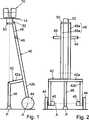
Ein Laserscanner
Der Messkopf
Eine Steuer- und Auswertevorrichtung
Mittels der (schnellen) Drehung des Rotorspiegels
Jeder Messpunkt X umfasst außer der Distanz d zum Zentrums C10 des Laserscanners
Um eine Szene aus verschiedenen Richtungen erfassen zu können, werden mehrere Scans von unterschiedlichen Standorten aus erzeugt und danach registriert bezüglich eines gemeinsamen Koordinatensystem der Szene. Der Laserscanner
Der manuell verfahrbare Trolley
Vom Fahrgestell
Der Laserscanner
Typische Abmessungen sind beispielsweise, dass das Zentrum C10 des Laserscanners
Der Trolley
Bei der ersten Betriebsart des Laserscanners
Die Steuer- und Auswertevorrichtung
Eine höhere Anzahl von Rädern, beispielsweise ein zusätzliches drittes Rad, welches lenkbar sein kann, oder insgesamt vier Räder, stabilisiert die Bewegung des Trolleys
Vorzugsweise weisen der Laserscanner
Bei der zweiten Betriebsart verfeinern die Daten der besagten Sensoren die Daten der Wegmessvorrichtung des Trolleys
BezugszeichenlisteLIST OF REFERENCE NUMBERS
- 1010
- Laserscannerlaser scanner
- 1212
- Messkopfprobe
- 1414
- Fußfoot
- 1616
- Spiegelmirror
- 1717
- Lichtsenderlight source
- 1818
- SendelichtstrahlTransmitted light beam
- 2020
- EmpfangslichtstrahlReception light beam
- 2121
- Lichtempfängerlight receiver
- 2222
- Steuer- und AuswertevorrichtungControl and evaluation device
- 4040
- TrolleyTrolley
- 4242
- Fahrgestellchassis
- 42a42a
- Querträgercrossbeam
- 42b42b
- Lagercamp
- 4444
- Radwheel
- 4545
- Encoderencoder
- 4646
- StützfußSupport foot
- 4848
- Armpoor
- 4848
- VierkantprofilSquare profile
- 4949
- Handgriffhandle
- 5050
- Montageplattemounting plate
- 5252
- Montagevorrichtungmounter
- 52a52a
- MontageschraubeMounting screw
- AA
- Achseaxis
- C10C10
- Zentrum des LaserscannersCenter of the laser scanner
- dd
- Distanzdistance
- OO
- Objektobject
- PP
- Standpunktposition
- XX
- Messpunktmeasuring point
Claims (8)
Translated fromGermanPriority Applications (6)
| Application Number | Priority Date | Filing Date | Title |
|---|---|---|---|
| DE102010033561ADE102010033561B3 (en) | 2010-07-29 | 2010-07-29 | Device for optically scanning and measuring an environment |
| CN201180046896.1ACN103154770B (en) | 2010-07-29 | 2011-07-01 | Device for optically scanning and measuring an environment |
| US13/699,001US8699036B2 (en) | 2010-07-29 | 2011-07-01 | Device for optically scanning and measuring an environment |
| GB1303599.3AGB2496087B (en) | 2010-07-29 | 2011-07-01 | Device for optically scanning and measuring an environment |
| JP2013520990AJP5490321B2 (en) | 2010-07-29 | 2011-07-01 | Device for optically scanning and measuring the surrounding environment |
| PCT/EP2011/003264WO2012013280A1 (en) | 2010-07-29 | 2011-07-01 | Device for optically scanning and measuring an environment |
Applications Claiming Priority (1)
| Application Number | Priority Date | Filing Date | Title |
|---|---|---|---|
| DE102010033561ADE102010033561B3 (en) | 2010-07-29 | 2010-07-29 | Device for optically scanning and measuring an environment |
Publications (1)
| Publication Number | Publication Date |
|---|---|
| DE102010033561B3true DE102010033561B3 (en) | 2011-12-15 |
Family
ID=44628419
Family Applications (1)
| Application Number | Title | Priority Date | Filing Date |
|---|---|---|---|
| DE102010033561AExpired - Fee RelatedDE102010033561B3 (en) | 2010-07-29 | 2010-07-29 | Device for optically scanning and measuring an environment |
Country Status (6)
| Country | Link |
|---|---|
| US (1) | US8699036B2 (en) |
| JP (1) | JP5490321B2 (en) |
| CN (1) | CN103154770B (en) |
| DE (1) | DE102010033561B3 (en) |
| GB (1) | GB2496087B (en) |
| WO (1) | WO2012013280A1 (en) |
Cited By (15)
| Publication number | Priority date | Publication date | Assignee | Title |
|---|---|---|---|---|
| DE102012109481A1 (en) | 2012-10-05 | 2014-04-10 | Faro Technologies, Inc. | Device for optically scanning and measuring an environment |
| CN103857984A (en)* | 2012-01-25 | 2014-06-11 | 法罗技术股份有限公司 | Device for optically scanning and measuring an environment |
| DE102013110580A1 (en) | 2013-09-24 | 2015-03-26 | Faro Technologies, Inc. | Method for optically scanning and measuring a scene |
| WO2015119797A1 (en) | 2014-02-09 | 2015-08-13 | Faro Technologies, Inc. | Laser scanner and method of registering a scene |
| US9210288B2 (en) | 2009-11-20 | 2015-12-08 | Faro Technologies, Inc. | Three-dimensional scanner with dichroic beam splitters to capture a variety of signals |
| DE102014110992A1 (en) | 2014-08-01 | 2016-02-04 | Faro Technologies Inc. | Register a clustered scene with location tracking |
| DE102014110995A1 (en) | 2014-08-01 | 2016-02-04 | Faro Technologies, Inc. | Registration of a clustered scene with scan request |
| US9329271B2 (en) | 2010-05-10 | 2016-05-03 | Faro Technologies, Inc. | Method for optically scanning and measuring an environment |
| DE102014116904A1 (en) | 2014-11-19 | 2016-05-19 | Faro Technologies, Inc. | Method for optically scanning and measuring a scene and automatically generating a video |
| US9513107B2 (en) | 2012-10-05 | 2016-12-06 | Faro Technologies, Inc. | Registration calculation between three-dimensional (3D) scans based on two-dimensional (2D) scan data from a 3D scanner |
| US9529083B2 (en) | 2009-11-20 | 2016-12-27 | Faro Technologies, Inc. | Three-dimensional scanner with enhanced spectroscopic energy detector |
| DE102016117320A1 (en) | 2015-09-14 | 2017-03-16 | Zoller & Fröhlich GmbH | Mobile carrying unit |
| US10067231B2 (en) | 2012-10-05 | 2018-09-04 | Faro Technologies, Inc. | Registration calculation of three-dimensional scanner data performed between scans based on measurements by two-dimensional scanner |
| US10175037B2 (en) | 2015-12-27 | 2019-01-08 | Faro Technologies, Inc. | 3-D measuring device with battery pack |
| US11293754B2 (en)* | 2019-04-02 | 2022-04-05 | Topcon Corporation | Surveying instrument |
Families Citing this family (40)
| Publication number | Priority date | Publication date | Assignee | Title |
|---|---|---|---|---|
| DE102006031580A1 (en) | 2006-07-03 | 2008-01-17 | Faro Technologies, Inc., Lake Mary | Method and device for the three-dimensional detection of a spatial area |
| US9551575B2 (en) | 2009-03-25 | 2017-01-24 | Faro Technologies, Inc. | Laser scanner having a multi-color light source and real-time color receiver |
| DE102009015920B4 (en) | 2009-03-25 | 2014-11-20 | Faro Technologies, Inc. | Device for optically scanning and measuring an environment |
| US9113023B2 (en) | 2009-11-20 | 2015-08-18 | Faro Technologies, Inc. | Three-dimensional scanner with spectroscopic energy detector |
| DE102009057101A1 (en) | 2009-11-20 | 2011-05-26 | Faro Technologies, Inc., Lake Mary | Device for optically scanning and measuring an environment |
| DE102009055989B4 (en) | 2009-11-20 | 2017-02-16 | Faro Technologies, Inc. | Device for optically scanning and measuring an environment |
| US8942940B2 (en) | 2010-01-20 | 2015-01-27 | Faro Technologies, Inc. | Portable articulated arm coordinate measuring machine and integrated electronic data processing system |
| US9879976B2 (en) | 2010-01-20 | 2018-01-30 | Faro Technologies, Inc. | Articulated arm coordinate measurement machine that uses a 2D camera to determine 3D coordinates of smoothly continuous edge features |
| US9607239B2 (en) | 2010-01-20 | 2017-03-28 | Faro Technologies, Inc. | Articulated arm coordinate measurement machine having a 2D camera and method of obtaining 3D representations |
| US9628775B2 (en) | 2010-01-20 | 2017-04-18 | Faro Technologies, Inc. | Articulated arm coordinate measurement machine having a 2D camera and method of obtaining 3D representations |
| US9163922B2 (en) | 2010-01-20 | 2015-10-20 | Faro Technologies, Inc. | Coordinate measurement machine with distance meter and camera to determine dimensions within camera images |
| US9168654B2 (en) | 2010-11-16 | 2015-10-27 | Faro Technologies, Inc. | Coordinate measuring machines with dual layer arm |
| US8997362B2 (en) | 2012-07-17 | 2015-04-07 | Faro Technologies, Inc. | Portable articulated arm coordinate measuring machine with optical communications bus |
| DE102012107544B3 (en)* | 2012-08-17 | 2013-05-23 | Faro Technologies, Inc. | Optical scanning device i.e. laser scanner, for evaluating environment, has planetary gears driven by motor over vertical motor shaft and rotating measuring head relative to foot, where motor shaft is arranged coaxial to vertical axle |
| WO2014039623A1 (en) | 2012-09-06 | 2014-03-13 | Faro Technologies, Inc. | Laser scanner with additional sensing device |
| CN104620129A (en) | 2012-09-14 | 2015-05-13 | 法罗技术股份有限公司 | Laser scanner with dynamical adjustment of angular scan velocity |
| JP6176957B2 (en)* | 2013-03-18 | 2017-08-09 | 株式会社ミツトヨ | Shape measuring device |
| DE102013110581B4 (en) | 2013-09-24 | 2018-10-11 | Faro Technologies, Inc. | Method for optically scanning and measuring an environment and device therefor |
| DE102013017500B3 (en) | 2013-10-17 | 2015-04-02 | Faro Technologies, Inc. | Method and apparatus for optically scanning and measuring a scene |
| US9594250B2 (en) | 2013-12-18 | 2017-03-14 | Hexagon Metrology, Inc. | Ultra-portable coordinate measurement machine |
| US10175360B2 (en) | 2015-03-31 | 2019-01-08 | Faro Technologies, Inc. | Mobile three-dimensional measuring instrument |
| US10120075B2 (en) | 2016-08-19 | 2018-11-06 | Faro Technologies, Inc. | Using a two-dimensional scanner to speed registration of three-dimensional scan data |
| US10380749B2 (en) | 2016-09-26 | 2019-08-13 | Faro Technologies, Inc. | Device and method for indoor mobile mapping of an environment |
| US10282854B2 (en) | 2016-10-12 | 2019-05-07 | Faro Technologies, Inc. | Two-dimensional mapping system and method of operation |
| EP3367057B1 (en)* | 2017-02-23 | 2020-08-26 | Hexagon Technology Center GmbH | Surveying instrument for scanning an object and image acquisition of the object |
| US10824773B2 (en) | 2017-03-28 | 2020-11-03 | Faro Technologies, Inc. | System and method of scanning an environment and generating two dimensional images of the environment |
| JP6943528B2 (en)* | 2017-04-05 | 2021-10-06 | 株式会社トプコン | Laser scanner |
| US10782118B2 (en) | 2018-02-21 | 2020-09-22 | Faro Technologies, Inc. | Laser scanner with photogrammetry shadow filling |
| US11055532B2 (en) | 2018-05-02 | 2021-07-06 | Faro Technologies, Inc. | System and method of representing and tracking time-based information in two-dimensional building documentation |
| US10914569B2 (en) | 2018-10-08 | 2021-02-09 | Faro Technologies, Inc. | System and method of defining a path and scanning an environment |
| US11692811B2 (en) | 2018-10-08 | 2023-07-04 | Faro Technologies, Inc. | System and method of defining a path and scanning an environment |
| US10989532B2 (en)* | 2018-10-08 | 2021-04-27 | Faro Technologies, Inc. | System and method of defining a path and scanning an environment |
| US11024050B2 (en) | 2018-11-05 | 2021-06-01 | Faro Technologies, Inc. | System and method of scanning an environment |
| US11486701B2 (en) | 2019-02-06 | 2022-11-01 | Faro Technologies, Inc. | System and method for performing a real-time wall detection |
| JP7202242B2 (en)* | 2019-04-02 | 2023-01-11 | 株式会社トプコン | surveying equipment |
| JP7287824B2 (en)* | 2019-04-15 | 2023-06-06 | 株式会社トプコン | surveying equipment |
| US12229975B2 (en) | 2020-08-12 | 2025-02-18 | Faro Technologies, Inc. | Laser scanner with ultrawide-angle lens camera for registration |
| US11501478B2 (en) | 2020-08-17 | 2022-11-15 | Faro Technologies, Inc. | System and method of automatic room segmentation for two-dimensional laser floorplans |
| US12266072B2 (en)* | 2022-02-02 | 2025-04-01 | Faro Technologies, Inc. | Scan color restoration |
| CN115598662A (en)* | 2022-09-21 | 2023-01-13 | 浙江众智绘云信息科技有限责任公司(Cn) | Indoor live-action three-dimensional data acquisition device capable of rotating by 720 degrees |
Citations (4)
| Publication number | Priority date | Publication date | Assignee | Title |
|---|---|---|---|---|
| US20030137449A1 (en)* | 2002-01-22 | 2003-07-24 | E-Businesscontrols Corp. | GPS-enhanced system and method for automatically capturing and co-registering virtual models of a site |
| WO2006000552A1 (en)* | 2004-06-23 | 2006-01-05 | Leica Geosystems Ag | Scanner system and method for registering surfaces |
| US7193690B2 (en)* | 2003-12-29 | 2007-03-20 | Faro Technologies, Inc. | Laser scanner and method for optically scanning an environment |
| DE102009035336B3 (en)* | 2009-07-22 | 2010-11-18 | Faro Technologies, Inc., Lake Mary | Device for optical scanning and measuring of environment, has optical measuring device for collection of ways as ensemble between different centers returning from laser scanner |
Family Cites Families (188)
| Publication number | Priority date | Publication date | Assignee | Title |
|---|---|---|---|---|
| GB1112941A (en) | 1965-01-02 | 1968-05-08 | Smiths Industries Ltd | Improvements in or relating to scanning apparatus |
| AT307762B (en) | 1971-04-28 | 1973-06-12 | Eumig | Method and device for distance measurement |
| US3899145A (en) | 1973-07-20 | 1975-08-12 | Us Navy | Laser transmitting and receiving lens optics |
| US3945729A (en) | 1974-12-30 | 1976-03-23 | Stanford Research Institute | Combined ranging and color sensor |
| DD201245A1 (en) | 1981-10-16 | 1983-07-13 | Rolf Jurenz | OPTICAL ARRANGEMENT FOR AUTOMATIC SHARPENING |
| US4733961A (en) | 1983-03-07 | 1988-03-29 | Texas Instruments Incorporated | Amplifier for integrated laser/FLIR rangefinder |
| DE3340317A1 (en) | 1983-11-08 | 1984-08-16 | Walter 4790 Paderborn Hesse | Test set for the simultaneous orientation and height determination of points in cavities where access is difficult |
| CA1268654A (en) | 1985-10-24 | 1990-05-08 | Arkady Kutman | Camera support and housing |
| DE3623343C1 (en) | 1986-07-11 | 1989-12-21 | Bodenseewerk Geraetetech | Optical viewfinder with rosette scanning |
| US5155684A (en)* | 1988-10-25 | 1992-10-13 | Tennant Company | Guiding an unmanned vehicle by reference to overhead features |
| US4984881A (en) | 1989-12-19 | 1991-01-15 | Ebara Corporation | Rotation supporting device of a polygon mirror |
| CA2038818A1 (en) | 1990-03-30 | 1991-10-01 | Akio Nagamune | Distance measuring method and apparatus therefor |
| US5675326A (en)* | 1990-04-11 | 1997-10-07 | Auto-Sense, Ltd. | Method of determining optimal detection beam locations using reflective feature mapping |
| SE466726B (en) | 1990-08-20 | 1992-03-23 | Kent Lennartsson | DISTRIBUTED COMPUTER SYSTEM DEVICE |
| DE4027990C1 (en) | 1990-09-04 | 1992-02-20 | Messerschmitt-Boelkow-Blohm Gmbh, 8012 Ottobrunn, De | Laser ranging device - uses modulated semiconductor laser and phase sensitive rectifier |
| JPH04115108A (en) | 1990-09-05 | 1992-04-16 | Matsushita Electric Ind Co Ltd | Three-dimensional scanner |
| US5371347A (en) | 1991-10-15 | 1994-12-06 | Gap Technologies, Incorporated | Electro-optical scanning system with gyrating scan head |
| JP2969009B2 (en) | 1991-02-22 | 1999-11-02 | 株式会社リコー | Axial mirror deflector |
| US5231470A (en) | 1991-09-06 | 1993-07-27 | Koch Stephen K | Scanning system for three-dimensional object digitizing |
| JPH0572477A (en) | 1991-09-13 | 1993-03-26 | Toshiba Corp | Afocal optical device |
| US5918029A (en) | 1996-09-27 | 1999-06-29 | Digital Equipment Corporation | Bus interface slicing mechanism allowing for a control/data-path slice |
| DE4222642A1 (en) | 1992-07-10 | 1994-01-13 | Bodenseewerk Geraetetech | Imaging sensor unit |
| US5313261A (en) | 1992-07-13 | 1994-05-17 | Applied Remote Technology Inc. | Method and apparatus for faithful gray scale representation of under water laser images |
| US5329347A (en) | 1992-09-16 | 1994-07-12 | Varo Inc. | Multifunction coaxial objective system for a rangefinder |
| US5402365A (en)* | 1992-10-28 | 1995-03-28 | Motorola, Inc. | Differential odometer dynamic calibration method and apparatus therefor |
| DE4340756C5 (en) | 1992-12-08 | 2006-08-10 | Sick Ag | Laser range finding device |
| DE4303804C2 (en) | 1993-02-10 | 1996-06-27 | Leuze Electronic Gmbh & Co | Distance measuring device |
| JPH07128051A (en)* | 1993-11-02 | 1995-05-19 | Sekisui Chem Co Ltd | Unevenness survey system |
| JPH07209080A (en) | 1993-12-28 | 1995-08-11 | Amberg Measuring Technik Ltd | Optical scanning device |
| JPH07218261A (en) | 1994-02-03 | 1995-08-18 | Nikon Corp | Laser projector |
| IL108646A0 (en) | 1994-02-14 | 1995-03-15 | Israel State | Opto-mechanical system |
| JPH07229963A (en) | 1994-02-21 | 1995-08-29 | Oki Electric Ind Co Ltd | Method for track detection |
| SE506753C2 (en) | 1995-05-02 | 1998-02-09 | Tokimec Inc | Device for determining the shape of a road surface |
| JPH0821714A (en)* | 1994-05-06 | 1996-01-23 | Tokimec Inc | Road-surface shape measuring device |
| JPH0815413A (en) | 1994-06-24 | 1996-01-19 | Mitsubishi Electric Corp | Distance measuring device |
| JP3619545B2 (en) | 1994-08-23 | 2005-02-09 | オリンパス株式会社 | Camera ranging device |
| US5517297A (en) | 1994-10-13 | 1996-05-14 | Hughes Aircraft Company | Rangefinder with transmitter, receiver, and viewfinder on a single common optical axis |
| US5793993A (en) | 1995-01-26 | 1998-08-11 | General Magic, Inc. | Method for transmitting bus commands and data over two wires of a serial bus |
| JP3582918B2 (en) | 1995-02-14 | 2004-10-27 | 株式会社トプコン | Laser surveying machine |
| DE19521771A1 (en) | 1995-06-20 | 1997-01-02 | Jan Michael Mrosik | FMCW distance measuring method |
| DE69634771T2 (en) | 1995-10-30 | 2006-02-02 | Kabushiki Kaisha Topcon | ROTATION LASER SYSTEM |
| US5734417A (en) | 1995-12-05 | 1998-03-31 | Yokogawa Precision Corporation | Visual presentation equipment |
| US20020014533A1 (en) | 1995-12-18 | 2002-02-07 | Xiaxun Zhu | Automated object dimensioning system employing contour tracing, vertice detection, and forner point detection and reduction methods on 2-d range data maps |
| DE19601875C2 (en) | 1996-01-19 | 1999-08-19 | Siemens Ag | Method and device for eliminating interference from FMCW radar |
| DE19607345A1 (en) | 1996-02-27 | 1997-08-28 | Sick Ag | Laser distance determination device |
| US5936721A (en) | 1996-03-18 | 1999-08-10 | Kabushiki Kaisha Topcon | Guide beam direction setting apparatus |
| JP3908297B2 (en) | 1996-03-19 | 2007-04-25 | 株式会社トプコン | Laser surveyor |
| US5988862A (en) | 1996-04-24 | 1999-11-23 | Cyra Technologies, Inc. | Integrated system for quickly and accurately imaging and modeling three dimensional objects |
| JPH102714A (en) | 1996-06-19 | 1998-01-06 | Canon Inc | Measurement method and device |
| US6057915A (en) | 1996-06-21 | 2000-05-02 | Thermotrex Corporation | Projectile tracking system |
| KR100268048B1 (en) | 1996-10-28 | 2000-11-01 | 고바야시 마사키 | Underwater laser imaging apparatus |
| JPH10246863A (en) | 1997-03-05 | 1998-09-14 | Sankyo Seiki Mfg Co Ltd | Rotating polygon mirror type light deflector |
| WO1998044287A1 (en) | 1997-03-28 | 1998-10-08 | Thieltges Gary P | Motion stable camera support system |
| US6069700A (en) | 1997-07-31 | 2000-05-30 | The Boeing Company | Portable laser digitizing system for large parts |
| DE19806288A1 (en) | 1998-02-16 | 1999-08-26 | Fraunhofer Ges Forschung | Laser scanner measuring system |
| EP1062525B1 (en) | 1998-03-10 | 2003-05-14 | Riegl Laser Measurement Systems Gmbh | Method for monitoring objects or an object area |
| DE19811550C2 (en) | 1998-03-18 | 2002-06-27 | Bosch Gmbh Robert | Method and circuit arrangement for generating frequency signals |
| EP0949524A1 (en) | 1998-04-07 | 1999-10-13 | Fujifilm Electronic Imaging Limited | Rotatable mirror assembly |
| EP0952427B1 (en)* | 1998-04-24 | 2004-03-03 | Inco Limited | Automated guided apparatus |
| JP3835016B2 (en) | 1998-10-16 | 2006-10-18 | 三菱電機株式会社 | Laser radar equipment |
| DE19850118A1 (en) | 1998-10-30 | 2000-05-11 | Siemens Ag | Profile measurement system and method for implementation |
| JP4088906B2 (en) | 1998-12-16 | 2008-05-21 | 株式会社トプコン | Photo detector of surveying instrument |
| JP4180718B2 (en) | 1999-01-29 | 2008-11-12 | 株式会社トプコン | Rotating laser device |
| JP2000249546A (en) | 1999-02-26 | 2000-09-14 | Seiko Precision Inc | Portable small-sized electronic measure |
| ATE305607T1 (en) | 1999-04-19 | 2005-10-15 | Fraunhofer Ges Forschung | IMAGE EDITING TO PREPARE A TEXTURE ANALYSIS |
| WO2000063645A1 (en) | 1999-04-19 | 2000-10-26 | Leica Geosystems Ag | Indirect position determination with the aid of a tracker |
| DE19928958A1 (en) | 1999-05-22 | 2000-11-23 | Volkswagen Ag | Laser scanner with reception unit having spherical lens having recess with optical axis orthogonal to axis of rotation, for use in automobiles |
| EP1067361A1 (en) | 1999-07-06 | 2001-01-10 | Datalogic S.P.A. | Method and a device for measuring the distance of an object |
| DE59901809D1 (en) | 1999-08-31 | 2002-07-25 | Leica Geosystems Ag | Tachymeter telescope |
| US6650402B2 (en) | 2000-02-10 | 2003-11-18 | Oceanit Laboratories, Inc. | Omni-directional cloud height indicator |
| US6825923B2 (en) | 2000-03-10 | 2004-11-30 | Hamar Laser Instruments, Inc. | Laser alignment system with plural lasers for impingement on a single target |
| JP4613337B2 (en) | 2000-05-29 | 2011-01-19 | 株式会社ニコン | microscope |
| US6750873B1 (en) | 2000-06-27 | 2004-06-15 | International Business Machines Corporation | High quality texture reconstruction from multiple scans |
| EP1299691B1 (en) | 2000-07-13 | 2004-12-08 | Werth Messtechnik GmbH | Method for carrying out the non-contact measurement of geometries of objects |
| US6734410B2 (en) | 2000-08-30 | 2004-05-11 | Pentax Precision Co., Ltd. | Surveying instrument having an optical distance meter and an autofocus system, and a surveying instrument having a detachable autofocus system |
| US6639684B1 (en) | 2000-09-13 | 2003-10-28 | Nextengine, Inc. | Digitizer using intensity gradient to image features of three-dimensional objects |
| US7076420B1 (en) | 2000-10-26 | 2006-07-11 | Cypress Semiconductor Corp. | Emulator chip/board architecture and interface |
| FR2817339B1 (en) | 2000-11-24 | 2004-05-14 | Mensi | THREE-DIMENSIONAL LIFTING DEVICE OF A LASER EMISSION SCENE |
| JP4595197B2 (en) | 2000-12-12 | 2010-12-08 | 株式会社デンソー | Distance measuring device |
| US7101300B2 (en) | 2001-01-23 | 2006-09-05 | Black & Decker Inc. | Multispeed power tool transmission |
| DE10137241A1 (en) | 2001-03-15 | 2002-09-19 | Tecmath Ag | Arrangement, for detecting and measuring objects, optically projects markers onto object, records partial views of object in global coordinate system using information re-detected markers |
| DE10112833C1 (en) | 2001-03-16 | 2003-03-13 | Hilti Ag | Method and device for electro-optical distance measurement |
| US6847436B2 (en) | 2001-04-10 | 2005-01-25 | Faro Laser Trackers, Llc | Chopper-stabilized absolute distance meter |
| JP4530571B2 (en) | 2001-04-16 | 2010-08-25 | Hoya株式会社 | 3D image detection device |
| US6649208B2 (en) | 2001-04-17 | 2003-11-18 | Wayne E. Rodgers | Apparatus and method for thin film deposition onto substrates |
| US7190465B2 (en) | 2001-08-30 | 2007-03-13 | Z + F Zoller & Froehlich Gmbh | Laser measurement system |
| DE20208077U1 (en) | 2001-08-30 | 2002-09-26 | Z+F Zoller & Fröhlich GmbH, 88239 Wangen | Laser measurement system |
| AT412028B (en) | 2001-11-09 | 2004-08-26 | Riegl Laser Measurement Sys | DEVICE FOR RECORDING AN OBJECT SPACE |
| JP2003156330A (en) | 2001-11-22 | 2003-05-30 | Nec Corp | Airborne topography-measuring apparatus and method |
| AU2003223173A1 (en) | 2002-02-14 | 2003-09-04 | Faro Technologies, Inc. | Portable coordinate measurement machine with integrated line laser scanner |
| AT411299B (en) | 2002-03-04 | 2003-11-25 | Riegl Laser Measurement Sys | METHOD FOR RECORDING AN OBJECT SPACE |
| JP4004316B2 (en) | 2002-03-20 | 2007-11-07 | 株式会社トプコン | Surveying device and method for acquiring image data using surveying device |
| GB0211473D0 (en)* | 2002-05-18 | 2002-06-26 | Aea Technology Plc | Railway surveying |
| JP2004037317A (en) | 2002-07-04 | 2004-02-05 | Murata Mfg Co Ltd | Three-dimensional shape measuring method and three-dimensional shape measuring device |
| DE10232028C5 (en) | 2002-07-16 | 2011-07-07 | Leuze electronic GmbH + Co. KG, 73277 | Optical sensor |
| JP2004109106A (en) | 2002-07-22 | 2004-04-08 | Fujitsu Ltd | Surface defect inspection method and surface defect inspection device |
| JP4121803B2 (en) | 2002-08-08 | 2008-07-23 | 株式会社トプコン | Lightwave distance measuring device |
| JP2004093504A (en) | 2002-09-03 | 2004-03-25 | Topcon Corp | Surveying equipment |
| DE10244643A1 (en) | 2002-09-25 | 2004-04-08 | Ibeo Automobile Sensor Gmbh | Optoelectronic position monitoring system for road vehicle has two pulsed lasers, sensor and mechanical scanner with rotating mirror at 45 degrees to shaft with calibration disk adjacent to reader |
| JP4228132B2 (en) | 2002-10-18 | 2009-02-25 | 株式会社トプコン | Position measuring device |
| GB2395261A (en) | 2002-11-11 | 2004-05-19 | Qinetiq Ltd | Ranging apparatus |
| US7202941B2 (en) | 2002-11-26 | 2007-04-10 | Munro James F | Apparatus for high accuracy distance and velocity measurement and methods thereof |
| DE10261386A1 (en) | 2002-12-30 | 2004-07-08 | Robert Bosch Gmbh | Device for terminating two-wire lines |
| JP2004245832A (en) | 2003-01-22 | 2004-09-02 | Pentax Corp | Multi-beam scanning color inspection system |
| US7145926B2 (en) | 2003-01-24 | 2006-12-05 | Peter Vitruk | RF excited gas laser |
| DE10304188A1 (en) | 2003-01-29 | 2004-08-19 | Iqsun Gmbh | Three-dimensional scanner has rotor consisting at least partly of transparent material and multiple parts and inclined rotatable mirror in form of mirroring on surface of rotor part |
| DE10305010B4 (en) | 2003-02-07 | 2012-06-28 | Robert Bosch Gmbh | Apparatus and method for image formation |
| US20040221790A1 (en) | 2003-05-02 | 2004-11-11 | Sinclair Kenneth H. | Method and apparatus for optical odometry |
| JP2005069700A (en) | 2003-08-25 | 2005-03-17 | East Japan Railway Co | 3D data acquisition device |
| JP2005077379A (en) | 2003-09-03 | 2005-03-24 | Denso Corp | Radar device |
| DE10348019A1 (en) | 2003-10-15 | 2005-05-25 | Henkel Kgaa | Method for computer-aided simulation of a machine arrangement, simulation device, computer-readable storage medium and computer program element |
| US7307701B2 (en) | 2003-10-30 | 2007-12-11 | Raytheon Company | Method and apparatus for detecting a moving projectile |
| JP4344224B2 (en) | 2003-11-21 | 2009-10-14 | 浜松ホトニクス株式会社 | Optical mask and MOPA laser device |
| AT413453B (en) | 2003-11-21 | 2006-03-15 | Riegl Laser Measurement Sys | DEVICE FOR RECORDING AN OBJECT ROOM |
| DE10359415A1 (en) | 2003-12-16 | 2005-07-14 | Trimble Jena Gmbh | Method for calibrating a surveying device |
| DE20320216U1 (en) | 2003-12-29 | 2004-03-18 | Iqsun Gmbh | laser scanner |
| US6893133B1 (en) | 2004-01-15 | 2005-05-17 | Yin S. Tang | Single panel color image projection system |
| US7140213B2 (en) | 2004-02-21 | 2006-11-28 | Strattec Security Corporation | Steering column lock apparatus and method |
| WO2005084248A2 (en) | 2004-03-01 | 2005-09-15 | Quantapoint, Inc | Method and apparatus for creating a registration network of a scene |
| DE102004015111A1 (en) | 2004-03-27 | 2005-10-20 | Fraunhofer Ges Forschung | Determining position, orientation of navigating system, e.g. robot, involves determining parameters of translation, rotation transformations of distance measurement curve to determine characteristic associations between transformed curves |
| DE102004028090A1 (en) | 2004-06-09 | 2005-12-29 | Robert Bosch Gmbh | Method for calibrating a sensor for vehicle interior monitoring |
| DE602005019499D1 (en) | 2004-07-15 | 2010-04-08 | Hitachi Ltd | Vehicle control system |
| WO2006121457A2 (en) | 2004-08-18 | 2006-11-16 | Sarnoff Corporation | Method and apparatus for performing three-dimensional computer modeling |
| US7352446B2 (en) | 2004-09-30 | 2008-04-01 | Faro Technologies, Inc. | Absolute distance meter that measures a moving retroreflector |
| DE102004052075A1 (en) | 2004-10-26 | 2006-04-27 | Jungheinrich Ag | Node for a bus network, bus network and method for configuring the network |
| DE102005027208B4 (en) | 2004-11-16 | 2011-11-10 | Zoller & Fröhlich GmbH | Method for controlling a laser scanner |
| EP1659417A1 (en) | 2004-11-19 | 2006-05-24 | Leica Geosystems AG | Method for the determination of the orientation of an orientationindicator |
| GB2421383A (en) | 2004-12-07 | 2006-06-21 | Instro Prec Ltd | Surface profile measurement |
| US7477359B2 (en) | 2005-02-11 | 2009-01-13 | Deltasphere, Inc. | Method and apparatus for making and displaying measurements based upon multiple 3D rangefinder data sets |
| AU2005200937A1 (en) | 2005-03-02 | 2006-09-21 | Maptek Pty Ltd | Imaging system |
| JP2006268260A (en) | 2005-03-23 | 2006-10-05 | Seiko Epson Corp | Data transfer control device and electronic device |
| DE102005018837A1 (en) | 2005-04-22 | 2006-10-26 | Robert Bosch Gmbh | Method and device for synchronizing two bus systems and arrangement of two bus systems |
| US7285793B2 (en) | 2005-07-15 | 2007-10-23 | Verisurf Software, Inc. | Coordinate tracking system, apparatus and method of use |
| CA2616613C (en) | 2005-07-26 | 2013-10-22 | Timothy D. Barfoot | Guidance, navigation, and control system for a vehicle |
| US20090100949A1 (en) | 2005-08-25 | 2009-04-23 | Thk Co., Ltd. | Motion guide apparatus |
| US7551771B2 (en) | 2005-09-20 | 2009-06-23 | Deltasphere, Inc. | Methods, systems, and computer program products for acquiring three-dimensional range information |
| AU2006306522B9 (en) | 2005-10-21 | 2011-12-08 | Deere & Company | Networked multi-role robotic vehicle |
| WO2007051972A1 (en)* | 2005-10-31 | 2007-05-10 | Qinetiq Limited | Navigation system |
| TWI287103B (en) | 2005-11-04 | 2007-09-21 | Univ Nat Chiao Tung | Embedded network controlled optical flow image positioning omni-direction motion system |
| DE102005056265A1 (en) | 2005-11-14 | 2007-05-16 | Pilz Gmbh & Co Kg | Device and method for monitoring a room area, in particular for securing a danger zone of an automated system |
| US20070118269A1 (en) | 2005-11-18 | 2007-05-24 | Alex Gibson | Engine control unit to valve control unit interface |
| US20070122250A1 (en) | 2005-11-29 | 2007-05-31 | Mullner Nandor Jr | Double-headed screw |
| JP2007178943A (en) | 2005-12-28 | 2007-07-12 | Brother Ind Ltd | Image display device |
| US7995834B1 (en) | 2006-01-20 | 2011-08-09 | Nextengine, Inc. | Multiple laser scanner |
| US20070171394A1 (en) | 2006-01-25 | 2007-07-26 | Daniel Steiner | Flagstick with integrated reflectors for use with a laser range finder |
| US7994465B1 (en) | 2006-02-06 | 2011-08-09 | Microsoft Corporation | Methods and devices for improved charge management for three-dimensional and color sensing |
| US7430070B2 (en) | 2006-03-29 | 2008-09-30 | The Boeing Company | Method and system for correcting angular drift of laser radar systems |
| DE202006005643U1 (en) | 2006-03-31 | 2006-07-06 | Faro Technologies Inc., Lake Mary | Device for three-dimensional detection of a spatial area |
| US8117668B2 (en) | 2006-04-27 | 2012-02-14 | Stephen James Crampton | Optical scanning probe |
| DE102006024534A1 (en) | 2006-05-05 | 2007-11-08 | Zoller & Fröhlich GmbH | Laser scanner has rotary head in which mirror is mounted, in section of housing which has triangular cross-section at right angles to its axis |
| DE102006031580A1 (en) | 2006-07-03 | 2008-01-17 | Faro Technologies, Inc., Lake Mary | Method and device for the three-dimensional detection of a spatial area |
| EP1890168A1 (en) | 2006-08-18 | 2008-02-20 | Leica Geosystems AG | Laserscanner |
| FR2905235B1 (en) | 2006-08-29 | 2009-03-13 | Salomon Sa | PROTECTIVE HELMET AND METHOD OF MANUFACTURING THE SAME |
| JP5073256B2 (en) | 2006-09-22 | 2012-11-14 | 株式会社トプコン | POSITION MEASUREMENT DEVICE, POSITION MEASUREMENT METHOD, AND POSITION MEASUREMENT PROGRAM |
| JP5057734B2 (en) | 2006-09-25 | 2012-10-24 | 株式会社トプコン | Surveying method, surveying system, and surveying data processing program |
| JP2008096123A (en) | 2006-10-05 | 2008-04-24 | Keyence Corp | Optical displacement gauge, optical displacement measuring method, optical displacement measuring program, computer-readable memory medium and recording equipment |
| US7990397B2 (en) | 2006-10-13 | 2011-08-02 | Leica Geosystems Ag | Image-mapped point cloud with ability to accurately represent point coordinates |
| US9747698B2 (en) | 2006-10-21 | 2017-08-29 | Sam Stathis | System for accurately and precisely locating and marking a position in space using wireless communications and robotics |
| JP4897430B2 (en) | 2006-10-27 | 2012-03-14 | 三井造船株式会社 | Image information acquisition device |
| ITRM20060651A1 (en) | 2006-12-06 | 2008-06-07 | Enea Ente Nuove Tec | METHOD AND DEVICE THREE-DIMENSIONAL OPTICAL RADAR USING THREE RGB RANGES MODULATED BY LASER DIODES, IN PARTICULAR FOR METROLOGICAL AND FINE ARTS APPLICATIONS. |
| GB2447258A (en) | 2007-03-05 | 2008-09-10 | Geospatial Res Ltd | Camera mount for colour enhanced laser imagery |
| JP5376777B2 (en) | 2007-06-13 | 2013-12-25 | 三菱電機株式会社 | Radar equipment |
| DE502007001251D1 (en) | 2007-06-14 | 2009-09-17 | Trumpf Laser Marking Systems A | Gas-cooled laser device for highly compact laser beam sources |
| CA2597891A1 (en) | 2007-08-20 | 2009-02-20 | Marc Miousset | Multi-beam optical probe and system for dimensional measurement |
| US7798453B2 (en) | 2007-09-07 | 2010-09-21 | Quickset International, Inc. | Boresight apparatus and method of use |
| EP2212827B1 (en) | 2007-10-16 | 2019-09-11 | Accu-Sort System, Inc. | Dimensioning and barcode reading system |
| EP2053353A1 (en) | 2007-10-26 | 2009-04-29 | Leica Geosystems AG | Distance measuring method and corresponding device |
| US8051710B2 (en) | 2007-11-28 | 2011-11-08 | General Electric Company | Method and apparatus for balancing a rotor |
| JP5348449B2 (en) | 2007-12-25 | 2013-11-20 | カシオ計算機株式会社 | Distance measuring device and projector |
| DE102008014275B4 (en) | 2008-02-01 | 2017-04-13 | Faro Technologies, Inc. | Device for determining a distance to an object |
| DE102008014274B4 (en) | 2008-02-01 | 2020-07-09 | Faro Technologies, Inc. | Method and device for determining a distance to an object |
| US8152071B2 (en) | 2008-02-08 | 2012-04-10 | Motion Computing, Inc. | Multi-purpose portable computer with integrated devices |
| DE102008015536B4 (en) | 2008-03-25 | 2017-04-06 | Mtu Friedrichshafen Gmbh | Method for address assignment to injectors |
| JP5173536B2 (en) | 2008-04-02 | 2013-04-03 | シャープ株式会社 | Imaging apparatus and optical axis control method |
| JP5153483B2 (en) | 2008-06-30 | 2013-02-27 | 三菱電機株式会社 | Laser light source device |
| JP5688876B2 (en) | 2008-12-25 | 2015-03-25 | 株式会社トプコン | Calibration method for laser scanner measurement system |
| JP5478902B2 (en) | 2009-01-20 | 2014-04-23 | スタンレー電気株式会社 | Optical distance sensor |
| DE102009015922B4 (en) | 2009-03-25 | 2016-12-15 | Faro Technologies, Inc. | Method for optically scanning and measuring a scene |
| DE102009038964A1 (en) | 2009-08-20 | 2011-02-24 | Faro Technologies, Inc., Lake Mary | Method for optically scanning and measuring an environment |
| AT508634B1 (en) | 2009-08-28 | 2011-05-15 | Riegl Laser Measurement Sys | LASER CHANNEL FOR ASSEMBLING ON THE ROOF RACK OF A VEHICLE |
| AT508635B1 (en) | 2009-08-28 | 2011-05-15 | Riegl Laser Measurement Sys | LASER SCANNING DEVICE FOR MOUNTING ON A VEHICLE WITH PENDANT COUPLING |
| DE102010032725B4 (en) | 2010-07-26 | 2012-04-26 | Faro Technologies, Inc. | Device for optically scanning and measuring an environment |
| DE102010032726B3 (en) | 2010-07-26 | 2011-11-24 | Faro Technologies, Inc. | Device for optically scanning and measuring an environment |
| GB2497910B (en) | 2010-10-25 | 2013-10-09 | Faro Tech Inc | Automated warm-up and stability check for laser trackers |
| DE102010061382B4 (en) | 2010-12-21 | 2019-02-14 | Sick Ag | Opto-electronic sensor and method for detection and distance determination of objects |
| US8965579B2 (en) | 2011-01-28 | 2015-02-24 | Intouch Technologies | Interfacing with a mobile telepresence robot |
| DE202011051975U1 (en) | 2011-11-15 | 2013-02-20 | Sick Ag | Opto-electronic safety sensor with radio-based wireless interface |
| DE102012107544B3 (en) | 2012-08-17 | 2013-05-23 | Faro Technologies, Inc. | Optical scanning device i.e. laser scanner, for evaluating environment, has planetary gears driven by motor over vertical motor shaft and rotating measuring head relative to foot, where motor shaft is arranged coaxial to vertical axle |
- 2010
- 2010-07-29DEDE102010033561Apatent/DE102010033561B3/ennot_activeExpired - Fee Related
- 2011
- 2011-07-01WOPCT/EP2011/003264patent/WO2012013280A1/enactiveApplication Filing
- 2011-07-01JPJP2013520990Apatent/JP5490321B2/ennot_activeExpired - Fee Related
- 2011-07-01GBGB1303599.3Apatent/GB2496087B/ennot_activeExpired - Fee Related
- 2011-07-01CNCN201180046896.1Apatent/CN103154770B/ennot_activeExpired - Fee Related
- 2011-07-01USUS13/699,001patent/US8699036B2/enactiveActive
Patent Citations (4)
| Publication number | Priority date | Publication date | Assignee | Title |
|---|---|---|---|---|
| US20030137449A1 (en)* | 2002-01-22 | 2003-07-24 | E-Businesscontrols Corp. | GPS-enhanced system and method for automatically capturing and co-registering virtual models of a site |
| US7193690B2 (en)* | 2003-12-29 | 2007-03-20 | Faro Technologies, Inc. | Laser scanner and method for optically scanning an environment |
| WO2006000552A1 (en)* | 2004-06-23 | 2006-01-05 | Leica Geosystems Ag | Scanner system and method for registering surfaces |
| DE102009035336B3 (en)* | 2009-07-22 | 2010-11-18 | Faro Technologies, Inc., Lake Mary | Device for optical scanning and measuring of environment, has optical measuring device for collection of ways as ensemble between different centers returning from laser scanner |
Non-Patent Citations (1)
| Title |
|---|
| Brenneke, Ch. et al.:"Using 3D Laser Range Data for SLAM in Outdoor Environments", IEEE Proceedings of the International Conference on Intelligent Robots and Systems, Las Vegas, Oktober 2003, Seiten 188 bis 193* |
Cited By (32)
| Publication number | Priority date | Publication date | Assignee | Title |
|---|---|---|---|---|
| US9529083B2 (en) | 2009-11-20 | 2016-12-27 | Faro Technologies, Inc. | Three-dimensional scanner with enhanced spectroscopic energy detector |
| US9210288B2 (en) | 2009-11-20 | 2015-12-08 | Faro Technologies, Inc. | Three-dimensional scanner with dichroic beam splitters to capture a variety of signals |
| US9329271B2 (en) | 2010-05-10 | 2016-05-03 | Faro Technologies, Inc. | Method for optically scanning and measuring an environment |
| US9684078B2 (en) | 2010-05-10 | 2017-06-20 | Faro Technologies, Inc. | Method for optically scanning and measuring an environment |
| GB2512515B (en)* | 2012-01-25 | 2019-04-10 | Faro Tech Inc | Device for optically scanning and measuring an environment |
| CN103857984A (en)* | 2012-01-25 | 2014-06-11 | 法罗技术股份有限公司 | Device for optically scanning and measuring an environment |
| CN103857984B (en)* | 2012-01-25 | 2016-08-24 | 法罗技术股份有限公司 | Apparatus for optically scanning and measuring the environment |
| US9417056B2 (en) | 2012-01-25 | 2016-08-16 | Faro Technologies, Inc. | Device for optically scanning and measuring an environment |
| US10203413B2 (en) | 2012-10-05 | 2019-02-12 | Faro Technologies, Inc. | Using a two-dimensional scanner to speed registration of three-dimensional scan data |
| US9746559B2 (en) | 2012-10-05 | 2017-08-29 | Faro Technologies, Inc. | Using two-dimensional camera images to speed registration of three-dimensional scans |
| US11815600B2 (en) | 2012-10-05 | 2023-11-14 | Faro Technologies, Inc. | Using a two-dimensional scanner to speed registration of three-dimensional scan data |
| US9372265B2 (en) | 2012-10-05 | 2016-06-21 | Faro Technologies, Inc. | Intermediate two-dimensional scanning with a three-dimensional scanner to speed registration |
| US11112501B2 (en) | 2012-10-05 | 2021-09-07 | Faro Technologies, Inc. | Using a two-dimensional scanner to speed registration of three-dimensional scan data |
| US11035955B2 (en) | 2012-10-05 | 2021-06-15 | Faro Technologies, Inc. | Registration calculation of three-dimensional scanner data performed between scans based on measurements by two-dimensional scanner |
| US10739458B2 (en) | 2012-10-05 | 2020-08-11 | Faro Technologies, Inc. | Using two-dimensional camera images to speed registration of three-dimensional scans |
| US9513107B2 (en) | 2012-10-05 | 2016-12-06 | Faro Technologies, Inc. | Registration calculation between three-dimensional (3D) scans based on two-dimensional (2D) scan data from a 3D scanner |
| WO2014068406A2 (en) | 2012-10-05 | 2014-05-08 | Faro Technologies, Inc. | Device for optically scanning and measuring an environment |
| DE102012109481A1 (en) | 2012-10-05 | 2014-04-10 | Faro Technologies, Inc. | Device for optically scanning and measuring an environment |
| US9618620B2 (en) | 2012-10-05 | 2017-04-11 | Faro Technologies, Inc. | Using depth-camera images to speed registration of three-dimensional scans |
| US10067231B2 (en) | 2012-10-05 | 2018-09-04 | Faro Technologies, Inc. | Registration calculation of three-dimensional scanner data performed between scans based on measurements by two-dimensional scanner |
| US9739886B2 (en) | 2012-10-05 | 2017-08-22 | Faro Technologies, Inc. | Using a two-dimensional scanner to speed registration of three-dimensional scan data |
| DE102013110580A1 (en) | 2013-09-24 | 2015-03-26 | Faro Technologies, Inc. | Method for optically scanning and measuring a scene |
| DE102013110580B4 (en) | 2013-09-24 | 2024-05-23 | Faro Technologies, Inc. | Method for optically scanning and measuring a scene and laser scanner designed to carry out the method |
| WO2015119797A1 (en) | 2014-02-09 | 2015-08-13 | Faro Technologies, Inc. | Laser scanner and method of registering a scene |
| DE102014101587A1 (en) | 2014-02-09 | 2015-08-27 | Faro Technologies, Inc. | Registration of a scene with consistency check |
| DE102014110995A1 (en) | 2014-08-01 | 2016-02-04 | Faro Technologies, Inc. | Registration of a clustered scene with scan request |
| DE102014110992A1 (en) | 2014-08-01 | 2016-02-04 | Faro Technologies Inc. | Register a clustered scene with location tracking |
| DE102014116904B4 (en)* | 2014-11-19 | 2016-11-24 | Faro Technologies, Inc. | Method for optically scanning and measuring a scene and automatically generating a video |
| DE102014116904A1 (en) | 2014-11-19 | 2016-05-19 | Faro Technologies, Inc. | Method for optically scanning and measuring a scene and automatically generating a video |
| DE102016117320A1 (en) | 2015-09-14 | 2017-03-16 | Zoller & Fröhlich GmbH | Mobile carrying unit |
| US10175037B2 (en) | 2015-12-27 | 2019-01-08 | Faro Technologies, Inc. | 3-D measuring device with battery pack |
| US11293754B2 (en)* | 2019-04-02 | 2022-04-05 | Topcon Corporation | Surveying instrument |
Also Published As
| Publication number | Publication date |
|---|---|
| GB2496087B (en) | 2014-08-06 |
| CN103154770B (en) | 2015-02-18 |
| CN103154770A (en) | 2013-06-12 |
| US20130070250A1 (en) | 2013-03-21 |
| GB201303599D0 (en) | 2013-04-10 |
| JP5490321B2 (en) | 2014-05-14 |
| GB2496087A (en) | 2013-05-01 |
| US8699036B2 (en) | 2014-04-15 |
| JP2013535671A (en) | 2013-09-12 |
| WO2012013280A1 (en) | 2012-02-02 |
Similar Documents
| Publication | Publication Date | Title |
|---|---|---|
| DE102010033561B3 (en) | Device for optically scanning and measuring an environment | |
| DE102013110581B4 (en) | Method for optically scanning and measuring an environment and device therefor | |
| DE102009035336B3 (en) | Device for optical scanning and measuring of environment, has optical measuring device for collection of ways as ensemble between different centers returning from laser scanner | |
| EP1859298B1 (en) | Method and system for determining position and orientation of an object | |
| DE102015201317B4 (en) | Measuring a dimension on a surface | |
| EP1669715B1 (en) | Chassis measurement device | |
| EP2526378B1 (en) | Method and system for sensing the position of a vehicle | |
| EP2961343B1 (en) | Extraoral dental scanner | |
| EP3830518B1 (en) | Surface measuring device and method for a floor surface | |
| EP2643660B1 (en) | Rotating laser | |
| EP3791132B1 (en) | Surface measuring device and method for a headlamp test bench | |
| DE10112653A1 (en) | Position bearing system | |
| DE102012109481A1 (en) | Device for optically scanning and measuring an environment | |
| EP3264034A1 (en) | Measuring device with height measurement system and method for measuring a height | |
| DE3941144A1 (en) | COORDINATE MEASURING DEVICE FOR CONTACTLESS MEASUREMENT OF OBJECTS | |
| EP2726816B1 (en) | Construction measuring device for detecting, measuring and marking edges and corner points of bordering surfaces | |
| EP2620745A1 (en) | Measuring system with a measuring device and a scan module | |
| EP1641704A1 (en) | Movable sensor device on the loading means of a forklift | |
| WO1997006409A1 (en) | Process and device for the rapid detection of the position of a target marking | |
| EP2392731A2 (en) | Street construction machine and method for controlling the distance of a street construction machine moving on a ground surface | |
| EP2433837A1 (en) | Optical instrument and method for optical monitoring the surroundings of slowly moving vehicles | |
| DE102017209695A1 (en) | Method for controlling a platform, control unit and tilt angle measuring system for a working platform | |
| DE102016117320A1 (en) | Mobile carrying unit | |
| EP2542854B1 (en) | Device for measuring and/or adjusting a tool | |
| EP1408344B1 (en) | Survey apparatus and survey method using a laserscanner |
Legal Events
| Date | Code | Title | Description |
|---|---|---|---|
| R016 | Response to examination communication | ||
| R018 | Grant decision by examination section/examining division | ||
| R020 | Patent grant now final | Effective date:20120316 | |
| R119 | Application deemed withdrawn, or ip right lapsed, due to non-payment of renewal fee |