DE102010032724A1 - Device for optically scanning and measuring an environment - Google Patents
Device for optically scanning and measuring an environmentDownload PDFInfo
- Publication number
- DE102010032724A1 DE102010032724A1DE102010032724ADE102010032724ADE102010032724A1DE 102010032724 A1DE102010032724 A1DE 102010032724A1DE 102010032724 ADE102010032724 ADE 102010032724ADE 102010032724 ADE102010032724 ADE 102010032724ADE 102010032724 A1DE102010032724 A1DE 102010032724A1
- Authority
- DE
- Germany
- Prior art keywords
- laser scanner
- light beam
- transmitted light
- prism
- support structure
- Prior art date
- Legal status (The legal status is an assumption and is not a legal conclusion. Google has not performed a legal analysis and makes no representation as to the accuracy of the status listed.)
- Ceased
Links
Images


Classifications
- G—PHYSICS
- G01—MEASURING; TESTING
- G01B—MEASURING LENGTH, THICKNESS OR SIMILAR LINEAR DIMENSIONS; MEASURING ANGLES; MEASURING AREAS; MEASURING IRREGULARITIES OF SURFACES OR CONTOURS
- G01B11/00—Measuring arrangements characterised by the use of optical techniques
- G01B11/24—Measuring arrangements characterised by the use of optical techniques for measuring contours or curvatures
- G—PHYSICS
- G01—MEASURING; TESTING
- G01C—MEASURING DISTANCES, LEVELS OR BEARINGS; SURVEYING; NAVIGATION; GYROSCOPIC INSTRUMENTS; PHOTOGRAMMETRY OR VIDEOGRAMMETRY
- G01C15/00—Surveying instruments or accessories not provided for in groups G01C1/00 - G01C13/00
- G01C15/002—Active optical surveying means
- G—PHYSICS
- G01—MEASURING; TESTING
- G01S—RADIO DIRECTION-FINDING; RADIO NAVIGATION; DETERMINING DISTANCE OR VELOCITY BY USE OF RADIO WAVES; LOCATING OR PRESENCE-DETECTING BY USE OF THE REFLECTION OR RERADIATION OF RADIO WAVES; ANALOGOUS ARRANGEMENTS USING OTHER WAVES
- G01S17/00—Systems using the reflection or reradiation of electromagnetic waves other than radio waves, e.g. lidar systems
- G01S17/88—Lidar systems specially adapted for specific applications
- G01S17/89—Lidar systems specially adapted for specific applications for mapping or imaging
- G—PHYSICS
- G01—MEASURING; TESTING
- G01S—RADIO DIRECTION-FINDING; RADIO NAVIGATION; DETERMINING DISTANCE OR VELOCITY BY USE OF RADIO WAVES; LOCATING OR PRESENCE-DETECTING BY USE OF THE REFLECTION OR RERADIATION OF RADIO WAVES; ANALOGOUS ARRANGEMENTS USING OTHER WAVES
- G01S7/00—Details of systems according to groups G01S13/00, G01S15/00, G01S17/00
- G01S7/48—Details of systems according to groups G01S13/00, G01S15/00, G01S17/00 of systems according to group G01S17/00
- G01S7/497—Means for monitoring or calibrating
- G—PHYSICS
- G02—OPTICS
- G02B—OPTICAL ELEMENTS, SYSTEMS OR APPARATUS
- G02B26/00—Optical devices or arrangements for the control of light using movable or deformable optical elements
- G02B26/08—Optical devices or arrangements for the control of light using movable or deformable optical elements for controlling the direction of light
- G02B26/10—Scanning systems
- G02B26/105—Scanning systems with one or more pivoting mirrors or galvano-mirrors
- G—PHYSICS
- G02—OPTICS
- G02B—OPTICAL ELEMENTS, SYSTEMS OR APPARATUS
- G02B26/00—Optical devices or arrangements for the control of light using movable or deformable optical elements
- G02B26/08—Optical devices or arrangements for the control of light using movable or deformable optical elements for controlling the direction of light
- G02B26/10—Scanning systems
- G02B26/108—Scanning systems having one or more prisms as scanning elements
Landscapes
- Physics & Mathematics (AREA)
- General Physics & Mathematics (AREA)
- Engineering & Computer Science (AREA)
- Radar, Positioning & Navigation (AREA)
- Remote Sensing (AREA)
- Optics & Photonics (AREA)
- Computer Networks & Wireless Communication (AREA)
- Electromagnetism (AREA)
- Optical Radar Systems And Details Thereof (AREA)
- Length Measuring Devices By Optical Means (AREA)
- Mechanical Optical Scanning Systems (AREA)
Abstract
Translated fromGermanDescription
Translated fromGermanDie Erfindung betrifft eine Vorrichtung mit den Merkmalen des Oberbegriffs des Anspruches 1.The invention relates to a device having the features of the preamble of claim 1.
Mit einer aus der
Der Erfindung liegt die Aufgabe zu Grunde, eine Vorrichtung der eingangs genannten Art zu verbessern. Diese Aufgabe wird erfindungsgemäß durch eine Vorrichtung mit den Merkmalen des Anspruches 1 gelöst. Vorteilhafte Ausgestaltungen sind Gegenstand der Unteransprüche.The invention is based on the object to improve a device of the type mentioned. This object is achieved by a device with the features of claim 1. Advantageous embodiments are the subject of the dependent claims.
Die Komponenten des Laserscanners sind in zwei Teilen des Messkopfes und einer diese verbindenden Traverse der Tragstruktur angeordnet. Um das Gewicht des Laserscanners zu verringern, ist als Teil des Gehäuses eine Schale vorgesehen, vorzugsweise für jede der beiden Teile des Messkopfes je eine Schale, welche aus eifern leichten Material, beispielsweise Kunststoff, bestehen kann und welche die betreffenden Komponenten des Laserscanners zum Schutz abdeckt. Um wiederum die Schale zu schützen, ist ein Bügel vorgesehen, vorzugsweise für jede Schale je ein Bügel, welcher die Außenseite der Schale teilweise abdeckt und welcher ebenfalls aus einem leichten Material, beispielsweise Aluminium, bestehen kann.The components of the laser scanner are arranged in two parts of the measuring head and a cross member of the support structure connecting them. In order to reduce the weight of the laser scanner, a shell is provided as part of the housing, preferably a shell for each of the two parts of the measuring head, which can be made of lightweight material, for example plastic, and which covers the relevant components of the laser scanner for protection , In turn, to protect the shell, a bracket is provided, preferably for each shell depending on a bracket which partially covers the outside of the shell and which may also be made of a lightweight material, such as aluminum.
Die Tragstruktur, welche vorzugsweise aus Gewichtsgründen ebenfalls aus Aluminium besteht, weist vorzugsweise Wände auf, welche der Befestigung der Komponenten mit der Optik und dem rotierenden Spiegel dienen. Die Wände können auch die halboffenen Schalen schließen. Der Bügel läuft vorzugsweise entlang der Außenkanten und/oder schräg über die Außenflächen der Schale und ist an der Tragstruktur befestigt, vorzugsweise an seinen Enden, gegebenenfalls auch in seiner Mitte an einer der beiden Wände. In den Bügel können zusätzlich zur Schutzfunktion weitere Funktionen integriert sein.The support structure, which is also preferably made of aluminum for weight reasons, preferably has walls which serve to secure the components to the optics and the rotating mirror. The walls can also close the half-open shells. The bracket preferably runs along the outer edges and / or obliquely over the outer surfaces of the shell and is attached to the support structure, preferably at its ends, possibly also in its center on one of the two walls. In addition to the protective function, additional functions can be integrated in the stirrups.
Die Parameter des Laserscanners, insbesondere die Temperatur, können sich während des laufenden Betriebs ändern. Für eine Korrektur ist eine Vergleichsmessung notwendig. Es bietet sich daher an, den Fleck des Sendelichtstrahls zeitweise entlang eines Prismas zu bewegen, welches eine bekannte Geometrie und einen bekannte Distanz zum Zentrum des Laserscanners aufweist. Ferner weist das Prisma wenigstens zwei unterschiedliche Helligkeiten und/oder Farben auf, um unterschiedliche Signalpegel des Empfangslichtstrahls zu erzeugen. Die unterschiedlichen Helligkeiten und/oder Farben wechseln vorzugsweise entlang der Bewegungsrichtung des Flecks des Sendelichtstrahls ab.The parameters of the laser scanner, especially the temperature, may change during operation. For a correction a comparison measurement is necessary. It is therefore advisable to temporarily move the spot of the transmitted light beam along a prism which has a known geometry and a known distance to the center of the laser scanner. Furthermore, the prism has at least two different brightnesses and / or colors in order to generate different signal levels of the received light beam. The different brightnesses and / or colors preferably alternate along the direction of movement of the spot of the transmitted light beam.
Während der Rotation des Spiegels wird der Sendelichtstrahl bei jeder Umdrehung einmal auf die Traverse der Tragstruktur geworfen, ohne dass die Umgebung unterhalb davon gemessen werden kann. Vorzugsweise ist das Prisma daher an der Traverse ausgebildet. Eine bestimmte geometrische Form senkrecht zur Bewegungsrichtung des Flecks des Sendelichtstrahls (oder in Bewegungsrichtung) kann den Abbildungseigenschaften der empfangenden Optik Rechnung tragen und damit die resultierende Signalqualität kontrollieren. Die Steuer- und Auswertevorrichtung nimmt mittels der unterschiedlichen Helligkeiten und/oder Farben und der bekannten Distanz des Prismas eine (Korrektur der) Distanzkorrektur vor.During the rotation of the mirror, the transmitted light beam is thrown once at each revolution on the traverse of the support structure, without the environment can be measured below it. Preferably, the prism is therefore formed on the traverse. A certain geometric shape perpendicular to the direction of movement of the spot of the transmitted light beam (or in the direction of movement) can take into account the imaging properties of the receiving optics and thus control the resulting signal quality. The control and evaluation device makes a correction of the distance correction by means of the different brightnesses and / or colors and the known distance of the prism.
Für den Zusammenbau des Laserscanners weisen die Komponenten mechanische und elektrische Schnittstellen auf. Besonders zwischen den relativ zu einander drehbaren Teilen ist dann eine hohe Präzision erforderlich. Der Laserscanner weist daher ein Schwenkachsenmodul auf, welches als vormontierte Baugruppe einerseits den im stationären Bezugssystems des Laserscanners ruhenden Fuß und andererseits Teile aufweist, die an der Tragstruktur des relativ zum Fuß drehbaren Messkopfes zu befestigen sind. Die relativ zueinander drehbaren Schnittstellen sind dann ins Innere des Schnittstellenmoduls verlagert. Die Schnittstellen zwischen dem Schwenkachsenmodul und den weiteren Teilen des Messkopfes können einfach(er) ausgebildet werden, so dass sie beim Einführen des Schwenkachsenmoduls, beispielsweise in einen Aufnahmeschacht der Tragstruktur, in Einführrichtung geschlossen werden.For the assembly of the laser scanner, the components have mechanical and electrical interfaces. Especially between the relatively rotatable parts then high precision is required. The laser scanner therefore has a swivel axis module which, as a preassembled subassembly, has, on the one hand, the foot resting in the stationary reference system of the laser scanner and, on the other hand, parts which are to be fastened to the support structure of the measuring head rotatable relative to the foot. The relatively rotatable interfaces are then shifted into the interior of the interface module. The interfaces between the pivot axis module and the other parts of the measuring head can be easily (er) formed so that they are closed during insertion of the pivot axis module, for example, in a receiving shaft of the support structure, in the insertion direction.
Im Laserscanner produzieren die Motoren zur Rotation des Messkopfes und des Spiegels sowie die Steuer- und Auswertevorrichtung und die weitere Elektronik Wärme, die abgeführt werden muss. Der Laserscanner weist hierfür eine integrierte Kühlvorrichtung auf, basierend auf einer Lüftung. Die Luft wird hierzu von einem Lufteinlass in einen Zwischenraum zwischen der Tragstruktur und einer als Gehäuse dienenden Schale geleitet und gelangt von dort in einem gegenüber dem Inneren der Tragstruktur abgedichteten Ansaugkanal in das Innere der Kühlvorrichtung. Von dort bläst ein Lüfter die erwärmte Luft über einen weiteren, gegen das Innere der Tragstruktur abgedichteten Ausblaskanal und einen Luftauslass nach außen. Damit kann vorzugsweise die Wärme abgeführt werden ohne die Dichtigkeit zentraler Komponenten zu beeinträchtigen. Je ein Filter am Lufteinlass und Luftauslass verhindern das Eindringen von Staub und gröberen Schmutz in die Zwischenräume und Kanäle der Kühlvorrichtung. Der Lufteinlass und der Luftauslass sind, beispielsweise mittels Lamellen, so gerichtet, dass die Luftströme voneinander wegweisen, d. h. kreuzungsfrei sind in möglichst auseinander gespreizten Richtungen. Der Ansaugkanal und der Ausblaskanal, beispielsweise mit rechteckigem Profil, sind abgedichtet an das Gehäuse des Lüfters angeschlossen. Zudem können die Kanäle durch geeignete Stopfen bei Bedarf völlig abgedichtet werden. Die vorzugsweise zwei Schalen sind jeweils halboffen ausgebildet und jeweils durch eine Wand der Tragstruktur geschlossen, wobei vorzugsweise an genau eine der beiden Schalen der Lufteinlass und der Luftauslass münden, abgedichtet gegeneinander und gegenüber dem Zwischenraum. Eine Dichtung der außen angeordneten Schalen gegen die Tragstruktur gewährleistet damit eine vollständige Abdichtung des Laserscanners. Zusätzlich zu dieser Lüftung weist die Kühlvorrichtung vorzugsweise noch passive Kühlelemente auf, beispielsweise Kühlrippen und/oder Wärmeleitungen, um die Wärme (aus Teilbereichen des Inneren der Tragstruktur) zu den aktiven Kühlelementen zu transportieren. Dies kann die Wärme der Elektronik oder, wenn die Tragstruktur in zwei zueinander abgedichtete Hälften unterteilt ist, die Wärme aus der anderen Hälfte (ohne aktive Kühlelemente) sein.In the laser scanner, the motors for the rotation of the measuring head and the mirror as well as the control and evaluation device and the further electronics produce heat, which must be dissipated. For this purpose, the laser scanner has an integrated cooling device based on ventilation. For this purpose, the air is conducted from an air inlet into a gap between the support structure and a shell serving as a housing, and from there to the interior of the cooling device in a suction channel which is sealed against the interior of the support structure. From there, a fan blows the heated air over another, sealed against the interior of the support structure blow-out and an air outlet to the outside. Thus, preferably, the heat can be dissipated without affecting the tightness of central components. One filter each on the air inlet and outlet prevent the ingress of dust and coarse dirt into the interstices and channels of the cooler. The air inlet and the air outlet are, for example by means of fins, directed so that the air flows away from each other, ie crossing are in the widest possible spread directions. The intake passage and the exhaust passage, for example with rectangular profile, are sealed to the fan housing. In addition, the channels can be completely sealed by suitable plugs when needed. The preferably two shells are each formed semi-open and each closed by a wall of the support structure, preferably at exactly one of the two shells of the air inlet and the air outlet open, sealed against each other and opposite the gap. A seal of the outer shells against the support structure thus ensures a complete seal of the laser scanner. In addition to this ventilation, the cooling device preferably also has passive cooling elements, for example cooling fins and / or heat pipes, in order to transport the heat (from partial regions of the interior of the support structure) to the active cooling elements. This may be the heat of the electronics or, if the support structure is divided into two halves sealed to each other, the heat from the other half (without active cooling elements).
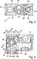
Im Folgenden ist die Erfindung anhand eines in der Zeichnung dargestellten Ausführungsbeispiels näher erläutert. Es zeigenIn the following the invention with reference to an embodiment shown in the drawing is explained in more detail. Show it
Ein Laserscanner
Der Messkopf
Eine Steuer- und Auswertevorrichtung
Mittels der (schnellen) Drehung des Rotorspiegels
Jeder Messpunkt X umfasst außer der Distanz d zum Zentrums C10 des Laserscanners
An die Steuer- und Auswertevorrichtung
Der Laserscanner
Auf der Außenseite jeder der beiden Schalen
Die beiden Bügel
Auf der Oberseite der Traverse
Aufgrund von Nichtlinearitäten in den elektronischen Bausteinen, beispielsweise im Lichtempfänger
Die Traverse
Zum Zusammenwirken mit dem Schneckenrad
Der Laserscanner
Der Ansaugkanal
Der Ausblaskanal
Vorzugsweise weist der Laserscanner
BezugszeichenlisteLIST OF REFERENCE NUMBERS
- 1010
- Laserscannerlaser scanner
- 1212
- Messkopfprobe
- 1414
- Fußfoot
- 1616
- Spiegelmirror
- 1717
- Lichtsenderlight source
- 1818
- SendelichtstrahlTransmitted light beam
- 2020
- EmpfangslichtstrahlReception light beam
- 2121
- Lichtempfängerlight receiver
- 2222
- Steuer- und AuswertevorrichtungControl and evaluation device
- 2424
- Anzeigevorrichtungdisplay device
- 3030
- Tragstruktursupporting structure
- 30a30a
- Traversetraverse
- 30b30b
- Wandwall
- 3232
- SchaleBowl
- 3434
- Bügelhanger
- 3636
- Prismaprism
- 4040
- SchwenkachsenmodulSwivel axis module
- 4242
- Schwenkachseswivel axis
- 4444
- Schneckenradworm
- 4646
- Innenkopfinner head
- 4747
- KreuzrollenlagerCrossed roller bearings
- 4848
- Außenkopfout of head
- 5050
- Encoderscheibeencoder disk
- 5252
- EncoderlesekopfEncoder read head
- 5454
- Schleifringslip ring
- 5555
- Steckkontakteplug contacts
- 5656
- Motorengine
- 5757
- Planetengetriebeplanetary gear
- 5858
- Schneckeslug
- 7070
- Kühlvorrichtungcooler
- 7272
- Ansaugkanalintake port
- 7474
- LüfterFan
- 7676
- Ausblaskanalblow-out
- 7878
- Kühlrippecooling fin
- 8080
- Lufteinlassair intake
- 8282
- Luftauslassair outlet
- C10C10
- Zentrum des LaserscannersCenter of the laser scanner
- dd
- Distanzdistance
- OO
- Objektobject
- XX
- Messpunktmeasuring point
- ZZ
- Zwischenraumgap
ZITATE ENTHALTEN IN DER BESCHREIBUNG QUOTES INCLUDE IN THE DESCRIPTION
Diese Liste der vom Anmelder aufgeführten Dokumente wurde automatisiert erzeugt und ist ausschließlich zur besseren Information des Lesers aufgenommen. Die Liste ist nicht Bestandteil der deutschen Patent- bzw. Gebrauchsmusteranmeldung. Das DPMA übernimmt keinerlei Haftung für etwaige Fehler oder Auslassungen.This list of the documents listed by the applicant has been generated automatically and is included solely for the better information of the reader. The list is not part of the German patent or utility model application. The DPMA assumes no liability for any errors or omissions.
Zitierte PatentliteraturCited patent literature
- DE 202006005643 U1[0002]DE 202006005643 U1[0002]
Claims (10)
Translated fromGermanPriority Applications (6)
| Application Number | Priority Date | Filing Date | Title |
|---|---|---|---|
| DE102010032724ADE102010032724A1 (en) | 2010-07-26 | 2010-07-26 | Device for optically scanning and measuring an environment |
| PCT/EP2011/003262WO2012013278A1 (en) | 2010-07-26 | 2011-07-01 | Device for optically scanning and measuring an environment |
| US13/812,235US20130201487A1 (en) | 2010-07-26 | 2011-07-01 | Device for optically scanning and measuring an environment |
| GB1303392.3AGB2496350B (en) | 2010-07-26 | 2011-07-01 | Device for optically scanning and measuring an environment |
| JP2013520988AJP2013539533A (en) | 2010-07-26 | 2011-07-01 | Device for optically scanning and measuring the ambient environment |
| CN201180046328.1ACN103119466B (en) | 2010-07-26 | 2011-07-01 | For carrying out the device of optical scanning and measurement to environment |
Applications Claiming Priority (1)
| Application Number | Priority Date | Filing Date | Title |
|---|---|---|---|
| DE102010032724ADE102010032724A1 (en) | 2010-07-26 | 2010-07-26 | Device for optically scanning and measuring an environment |
Publications (1)
| Publication Number | Publication Date |
|---|---|
| DE102010032724A1true DE102010032724A1 (en) | 2012-01-26 |
Family
ID=45443532
Family Applications (1)
| Application Number | Title | Priority Date | Filing Date |
|---|---|---|---|
| DE102010032724ACeasedDE102010032724A1 (en) | 2010-07-26 | 2010-07-26 | Device for optically scanning and measuring an environment |
Country Status (6)
| Country | Link |
|---|---|
| US (1) | US20130201487A1 (en) |
| JP (1) | JP2013539533A (en) |
| CN (1) | CN103119466B (en) |
| DE (1) | DE102010032724A1 (en) |
| GB (1) | GB2496350B (en) |
| WO (1) | WO2012013278A1 (en) |
Cited By (1)
| Publication number | Priority date | Publication date | Assignee | Title |
|---|---|---|---|---|
| EP3654062A1 (en) | 2018-11-16 | 2020-05-20 | Hexagon Technology Center GmbH | Distance measuring device with high signal dynamics and reference light path adapted thereto |
Families Citing this family (28)
| Publication number | Priority date | Publication date | Assignee | Title |
|---|---|---|---|---|
| DE102006031580A1 (en) | 2006-07-03 | 2008-01-17 | Faro Technologies, Inc., Lake Mary | Method and device for the three-dimensional detection of a spatial area |
| DE102009015920B4 (en) | 2009-03-25 | 2014-11-20 | Faro Technologies, Inc. | Device for optically scanning and measuring an environment |
| US9551575B2 (en) | 2009-03-25 | 2017-01-24 | Faro Technologies, Inc. | Laser scanner having a multi-color light source and real-time color receiver |
| US9210288B2 (en) | 2009-11-20 | 2015-12-08 | Faro Technologies, Inc. | Three-dimensional scanner with dichroic beam splitters to capture a variety of signals |
| DE102009057101A1 (en) | 2009-11-20 | 2011-05-26 | Faro Technologies, Inc., Lake Mary | Device for optically scanning and measuring an environment |
| US9113023B2 (en) | 2009-11-20 | 2015-08-18 | Faro Technologies, Inc. | Three-dimensional scanner with spectroscopic energy detector |
| DE102009055989B4 (en) | 2009-11-20 | 2017-02-16 | Faro Technologies, Inc. | Device for optically scanning and measuring an environment |
| US9529083B2 (en) | 2009-11-20 | 2016-12-27 | Faro Technologies, Inc. | Three-dimensional scanner with enhanced spectroscopic energy detector |
| US9879976B2 (en) | 2010-01-20 | 2018-01-30 | Faro Technologies, Inc. | Articulated arm coordinate measurement machine that uses a 2D camera to determine 3D coordinates of smoothly continuous edge features |
| US9628775B2 (en) | 2010-01-20 | 2017-04-18 | Faro Technologies, Inc. | Articulated arm coordinate measurement machine having a 2D camera and method of obtaining 3D representations |
| US9163922B2 (en) | 2010-01-20 | 2015-10-20 | Faro Technologies, Inc. | Coordinate measurement machine with distance meter and camera to determine dimensions within camera images |
| US8942940B2 (en) | 2010-01-20 | 2015-01-27 | Faro Technologies, Inc. | Portable articulated arm coordinate measuring machine and integrated electronic data processing system |
| US9607239B2 (en) | 2010-01-20 | 2017-03-28 | Faro Technologies, Inc. | Articulated arm coordinate measurement machine having a 2D camera and method of obtaining 3D representations |
| DE102010020925B4 (en) | 2010-05-10 | 2014-02-27 | Faro Technologies, Inc. | Method for optically scanning and measuring an environment |
| US9168654B2 (en) | 2010-11-16 | 2015-10-27 | Faro Technologies, Inc. | Coordinate measuring machines with dual layer arm |
| DE102012100609A1 (en) | 2012-01-25 | 2013-07-25 | Faro Technologies, Inc. | Device for optically scanning and measuring an environment |
| US8997362B2 (en) | 2012-07-17 | 2015-04-07 | Faro Technologies, Inc. | Portable articulated arm coordinate measuring machine with optical communications bus |
| DE102012107544B3 (en)* | 2012-08-17 | 2013-05-23 | Faro Technologies, Inc. | Optical scanning device i.e. laser scanner, for evaluating environment, has planetary gears driven by motor over vertical motor shaft and rotating measuring head relative to foot, where motor shaft is arranged coaxial to vertical axle |
| WO2014039623A1 (en) | 2012-09-06 | 2014-03-13 | Faro Technologies, Inc. | Laser scanner with additional sensing device |
| CN104620129A (en) | 2012-09-14 | 2015-05-13 | 法罗技术股份有限公司 | Laser scanner with dynamical adjustment of angular scan velocity |
| US10067231B2 (en) | 2012-10-05 | 2018-09-04 | Faro Technologies, Inc. | Registration calculation of three-dimensional scanner data performed between scans based on measurements by two-dimensional scanner |
| DE102012109481A1 (en) | 2012-10-05 | 2014-04-10 | Faro Technologies, Inc. | Device for optically scanning and measuring an environment |
| US9513107B2 (en) | 2012-10-05 | 2016-12-06 | Faro Technologies, Inc. | Registration calculation between three-dimensional (3D) scans based on two-dimensional (2D) scan data from a 3D scanner |
| EP2860546B1 (en)* | 2013-10-09 | 2019-08-07 | Hexagon Technology Center GmbH | Measuring device with a rotation mirror for optically scanning an environment |
| US9594250B2 (en) | 2013-12-18 | 2017-03-14 | Hexagon Metrology, Inc. | Ultra-portable coordinate measurement machine |
| CA172005S (en)* | 2016-12-01 | 2017-08-11 | Riegl Laser Measurement Systems Gmbh | Laser scanner for surveying, for topographical and distance measurement |
| US10782118B2 (en) | 2018-02-21 | 2020-09-22 | Faro Technologies, Inc. | Laser scanner with photogrammetry shadow filling |
| CN108931764A (en)* | 2018-05-21 | 2018-12-04 | 中国科学院合肥物质科学研究院 | A kind of laser pulse detector of the in-orbit calibration of laser ceilometer terrestrial positioning precision |
Citations (1)
| Publication number | Priority date | Publication date | Assignee | Title |
|---|---|---|---|---|
| DE202006005643U1 (en) | 2006-03-31 | 2006-07-06 | Faro Technologies Inc., Lake Mary | Device for three-dimensional detection of a spatial area |
Family Cites Families (18)
| Publication number | Priority date | Publication date | Assignee | Title |
|---|---|---|---|---|
| AU6215186A (en)* | 1985-09-06 | 1987-03-12 | University Of Liverpool, The | Displacement measurement |
| DE19607345A1 (en)* | 1996-02-27 | 1997-08-28 | Sick Ag | Laser distance determination device |
| KR100268048B1 (en)* | 1996-10-28 | 2000-11-01 | 고바야시 마사키 | Underwater laser imaging apparatus |
| DE19647152A1 (en)* | 1996-11-14 | 1998-05-28 | Sick Ag | Laser distance determination device |
| US6847436B2 (en)* | 2001-04-10 | 2005-01-25 | Faro Laser Trackers, Llc | Chopper-stabilized absolute distance meter |
| JP2004245832A (en)* | 2003-01-22 | 2004-09-02 | Pentax Corp | Multi-beam scanning color inspection system |
| US7145926B2 (en)* | 2003-01-24 | 2006-12-05 | Peter Vitruk | RF excited gas laser |
| KR20040068691A (en)* | 2003-01-27 | 2004-08-02 | 삼성전자주식회사 | Color illuminating system and projection type image display apparatus employing the same |
| JP4315327B2 (en)* | 2003-05-09 | 2009-08-19 | 極東産機株式会社 | Laser distance measuring device and laser distance meter calibration method |
| DE20320216U1 (en)* | 2003-12-29 | 2004-03-18 | Iqsun Gmbh | laser scanner |
| JP3908226B2 (en)* | 2004-02-04 | 2007-04-25 | 日本電産株式会社 | Scanning range sensor |
| EP1610091A1 (en)* | 2004-06-23 | 2005-12-28 | Leica Geosystems AG | Scanner system and method for surface acquisition |
| JP2006023330A (en)* | 2004-07-06 | 2006-01-26 | Takao Kobayashi | Optical filter having a plurality of optical characteristics and application thereof to meteorological observation |
| US7843572B2 (en)* | 2005-09-29 | 2010-11-30 | The General Hospital Corporation | Method and apparatus for optical imaging via spectral encoding |
| RU2412460C2 (en)* | 2006-04-10 | 2011-02-20 | Электролюкс Хоум Продактс Корпорейшн Н.В. | Household electric appliance incorporating fingerprint identification sensor |
| DE502007001251D1 (en)* | 2007-06-14 | 2009-09-17 | Trumpf Laser Marking Systems A | Gas-cooled laser device for highly compact laser beam sources |
| JP2009229255A (en)* | 2008-03-24 | 2009-10-08 | Hokuyo Automatic Co | Scanning range finder |
| JP5153483B2 (en)* | 2008-06-30 | 2013-02-27 | 三菱電機株式会社 | Laser light source device |
- 2010
- 2010-07-26DEDE102010032724Apatent/DE102010032724A1/ennot_activeCeased
- 2011
- 2011-07-01GBGB1303392.3Apatent/GB2496350B/ennot_activeExpired - Fee Related
- 2011-07-01JPJP2013520988Apatent/JP2013539533A/enactivePending
- 2011-07-01CNCN201180046328.1Apatent/CN103119466B/ennot_activeExpired - Fee Related
- 2011-07-01WOPCT/EP2011/003262patent/WO2012013278A1/enactiveApplication Filing
- 2011-07-01USUS13/812,235patent/US20130201487A1/ennot_activeAbandoned
Patent Citations (1)
| Publication number | Priority date | Publication date | Assignee | Title |
|---|---|---|---|---|
| DE202006005643U1 (en) | 2006-03-31 | 2006-07-06 | Faro Technologies Inc., Lake Mary | Device for three-dimensional detection of a spatial area |
Cited By (2)
| Publication number | Priority date | Publication date | Assignee | Title |
|---|---|---|---|---|
| EP3654062A1 (en) | 2018-11-16 | 2020-05-20 | Hexagon Technology Center GmbH | Distance measuring device with high signal dynamics and reference light path adapted thereto |
| US11428784B2 (en) | 2018-11-16 | 2022-08-30 | Hexagon Technology Center Gmbh | Distance measuring apparatus with high signal dynamics and a reference light path matched thereto |
Also Published As
| Publication number | Publication date |
|---|---|
| GB2496350B (en) | 2015-01-07 |
| JP2013539533A (en) | 2013-10-24 |
| WO2012013278A1 (en) | 2012-02-02 |
| GB201303392D0 (en) | 2013-04-10 |
| GB2496350A (en) | 2013-05-08 |
| CN103119466B (en) | 2015-09-23 |
| US20130201487A1 (en) | 2013-08-08 |
| CN103119466A (en) | 2013-05-22 |
Similar Documents
| Publication | Publication Date | Title |
|---|---|---|
| DE102010032723B3 (en) | Device for optically scanning and measuring an environment | |
| DE102010032725B4 (en) | Device for optically scanning and measuring an environment | |
| DE102010032726B3 (en) | Device for optically scanning and measuring an environment | |
| DE102010032724A1 (en) | Device for optically scanning and measuring an environment | |
| EP2005112B1 (en) | Apparatus and method for three-dimensional coverage of a spatial area | |
| DE102012105027B4 (en) | Laser scanner and method for driving a laser scanner | |
| DE102012107544B3 (en) | Optical scanning device i.e. laser scanner, for evaluating environment, has planetary gears driven by motor over vertical motor shaft and rotating measuring head relative to foot, where motor shaft is arranged coaxial to vertical axle | |
| EP3408719B1 (en) | Method for creating an environment map for an automatically moveable processing device | |
| DE112010000019T5 (en) | Method for optically scanning and measuring an environment | |
| DE102005012107B4 (en) | Measuring system and method for geodetic surveying of objects | |
| EP3014569B1 (en) | Inspection of the contoured surface of the underbody of a motor vehicle | |
| EP1068992A2 (en) | Device for assisting reversing | |
| DE112013004489T5 (en) | Laser scanner with dynamic setting of the angular scanning speed | |
| DE102009057101A1 (en) | Device for optically scanning and measuring an environment | |
| DE102013110581A1 (en) | Device for optically scanning and measuring an environment | |
| EP3233691A1 (en) | Position-determining system for an elevator | |
| EP2856755B1 (en) | Device and method for recording images of a vehicle underbody.. | |
| DE102010041490A1 (en) | Optical instrument and method for optical monitoring | |
| DE102017114617A1 (en) | Laser scanner with light | |
| DE102016213348A1 (en) | Optical arrangement for a LiDAR system, LiDAR system and working device | |
| DE102017105210A1 (en) | Optical radiation device for laser pulses with selective optics | |
| WO2019233701A1 (en) | Method and apparatus for measuring vibrations of an object using a drone | |
| EP4086568A1 (en) | Method and system for characterising vegetation | |
| DE10227299A1 (en) | Scanner for optical object detection | |
| EP2013642A1 (en) | Device and method for recording distance images |
Legal Events
| Date | Code | Title | Description |
|---|---|---|---|
| R016 | Response to examination communication | ||
| R016 | Response to examination communication | ||
| R002 | Refusal decision in examination/registration proceedings | ||
| R003 | Refusal decision now final |