DE102010032456A1 - Electric contactor - Google Patents
Electric contactorDownload PDFInfo
- Publication number
- DE102010032456A1 DE102010032456A1DE102010032456ADE102010032456ADE102010032456A1DE 102010032456 A1DE102010032456 A1DE 102010032456A1DE 102010032456 ADE102010032456 ADE 102010032456ADE 102010032456 ADE102010032456 ADE 102010032456ADE 102010032456 A1DE102010032456 A1DE 102010032456A1
- Authority
- DE
- Germany
- Prior art keywords
- armature
- coil
- contacts
- contactor according
- main
- Prior art date
- Legal status (The legal status is an assumption and is not a legal conclusion. Google has not performed a legal analysis and makes no representation as to the accuracy of the status listed.)
- Granted
Links
- 238000010791quenchingMethods0.000claimsdescription14
- 230000000171quenching effectEffects0.000claimsdescription13
- 238000012544monitoring processMethods0.000claimsdescription2
- 230000001681protective effectEffects0.000claimsdescription2
- 238000004804windingMethods0.000claimsdescription2
- 239000003990capacitorSubstances0.000description10
- 238000010586diagramMethods0.000description3
- 230000001419dependent effectEffects0.000description2
- 230000000694effectsEffects0.000description2
- 238000003466weldingMethods0.000description2
- BUHVIAUBTBOHAG-FOYDDCNASA-N(2r,3r,4s,5r)-2-[6-[[2-(3,5-dimethoxyphenyl)-2-(2-methylphenyl)ethyl]amino]purin-9-yl]-5-(hydroxymethyl)oxolane-3,4-diolChemical compoundCOC1=CC(OC)=CC(C(CNC=2C=3N=CN(C=3N=CN=2)[C@H]2[C@@H]([C@H](O)[C@@H](CO)O2)O)C=2C(=CC=CC=2)C)=C1BUHVIAUBTBOHAG-FOYDDCNASA-N0.000description1
- 238000010276constructionMethods0.000description1
- 238000001514detection methodMethods0.000description1
- 230000001627detrimental effectEffects0.000description1
- 230000005611electricityEffects0.000description1
- 238000004519manufacturing processMethods0.000description1
- 238000000034methodMethods0.000description1
- 238000011144upstream manufacturingMethods0.000description1
Images
Classifications
- H—ELECTRICITY
- H01—ELECTRIC ELEMENTS
- H01H—ELECTRIC SWITCHES; RELAYS; SELECTORS; EMERGENCY PROTECTIVE DEVICES
- H01H50/00—Details of electromagnetic relays
- H01H50/54—Contact arrangements
- H01H50/541—Auxiliary contact devices
- H—ELECTRICITY
- H01—ELECTRIC ELEMENTS
- H01H—ELECTRIC SWITCHES; RELAYS; SELECTORS; EMERGENCY PROTECTIVE DEVICES
- H01H50/00—Details of electromagnetic relays
- H01H50/54—Contact arrangements
- H01H50/62—Co-operating movable contacts operated by separate electrical actuating means
- H—ELECTRICITY
- H01—ELECTRIC ELEMENTS
- H01H—ELECTRIC SWITCHES; RELAYS; SELECTORS; EMERGENCY PROTECTIVE DEVICES
- H01H50/00—Details of electromagnetic relays
- H01H50/54—Contact arrangements
- H01H50/546—Contact arrangements for contactors having bridging contacts
Landscapes
- Physics & Mathematics (AREA)
- Electromagnetism (AREA)
- Relay Circuits (AREA)
Abstract
Translated fromGermanDescription
Translated fromGermanDie Erfindung betrifft ein elektrisches Schaltschütz nach dem Oberbegriff des unabhängigen Anspruchs 1. Ein derartiges Schaltschütz umfasst ein Gehäuse, zumindest zwei feste Hauptkontakte und eine Hauptkontaktbrücke, zumindest zwei feste Nebenkontakte und eine Nebenkontaktbrücke, wobei sowohl die Hauptkontakte, die Nebenkontakte wie auch die Kontaktbrücken im Gehäuse angeordnet sind. Ferner umfasst ein derartiges elektrisches Schaltschütz einen zur Betätigung der Hauptkontaktbrücken und Nebenkontaktbrücken vorgesehenen Anker. In einer ersten Schaltstellung sind sowohl die Hauptkontakte als auch die Nebenkontakte geöffnet, wobei sich der Anker in einer Ausgangslage befindet. In einer zweiten Schaltstellung sind die Nebenkontakte geschlossen und die Hauptkontakte geöffnet. Der Anker befindet sich dabei in einer Zwischenstellung. In einer dritten Schaltstellung sind sowohl die Nebenkontakte als auch die Hauptkontakte geschlossen, wobei sich der Anker in einer Endstellung befindet. Das Schaltschütz umfasst ferner zumindest eine elektrisch bestrombare Spule für einen elektromagnetischen Antrieb des Ankers, wobei eine durch das von der Spule erzeugte Magnetfeld auf den Anker wirkende Magnetkraft den Antrieb des Ankers bewirkt. Ferner ist ein Spulenjoch vorgesehen, welches einen magnetischen Rückschluss bildet. Schließlich umfasst ein derartiges Schaltschütz zudem Mittel zur Rückstellung des Ankers in die Ausgangslage. Eine durch die Mittel auf den Anker wirkende Rückstellkraft ist der Magnetkraft, die durch das Magnetfeld erzeugt wird, entgegengerichtet und außerdem in der Endstellung des Ankers größer als in der Zwischenstellung.The invention relates to an electrical contactor according to the preamble of
Derartige Schaltschütze werden üblicherweise verwendet, um über die Nebenkontakte, beispielsweise einen Kondensator, vorzuladen, bevor die Hauptkontakte geschlossen werden. Dies ist beispielsweise erforderlich, wenn über ein Schaltschütz eine Gleichspannung auf einen Umrichter oder einen Wechselrichter geschaltet wird. Am Eingang eines solchen Umrichters bzw. Wechselrichters befindet sich in der Regel ein großer Kondensator. Schaltet man die Gleichspannung über die Hauptkontakte direkt auf den Kondensator, fließt für eine gewisse Zeit praktisch ein Kurzschlussstrom, nämlich so lange, bis durch die Ladung des Kondensators ein Widerstand erzeugt wird. Die Zeitspanne, in welcher dieser hohe Kurzschlussstrom fließt, hängt von der Kapazität des Kondensators und dem Innenwiderstand der Quelle sowie dem Widerstand der Zuleitungen ab. Der hohe Strom ist schädlich für die Hauptkontakte und kann zum Verschweißen der Hauptkontakte führen. In jedem Fall wird die Lebensdauer herabgesetzt. Es ist Stand der Technik, den Kondensator über Nebenkontakte sowie über einen Widerstand vorzuladen, und erst danach die Hauptkontakte zu schließen.Such contactors are commonly used to pre-charge via the side contacts, such as a capacitor, before the main contacts are closed. This is necessary, for example, if a DC voltage is switched to a converter or an inverter via a contactor. At the entrance of such a converter or inverter is usually a large capacitor. If the DC voltage is switched directly to the capacitor via the main contacts, practically a short-circuit current flows for a certain time, namely until a resistance is generated by the charge of the capacitor. The period of time in which this high short-circuit current flows depends on the capacitance of the capacitor and the internal resistance of the source and the resistance of the supply lines. The high current is detrimental to the main contacts and can lead to welding of the main contacts. In any case, the life is reduced. It is state of the art to precharge the capacitor via secondary contacts and via a resistor, and only then to close the main contacts.
Ein Schaltschütz der eingangsgenannten Art ist aus
Dem aus dem Stand der Technik bekannten Schaltschützen ist gemein, dass die Zeitdauer, in welcher die Nebenkontakte bereits geschlossen sind, bevor die Hauptkontakte geschlossen werden, nicht variiert werden kann. Der Anker, der auf seinem Weg von einer Ausgangslage zur Endstellung zunächst die Nebenkontakte und dann die Hauptkontakte schließt, schaltet sozusagen von der Ausgangslage zur Endstellung durch. Eine Zwischenstellung des Ankers, in der lediglich die Nebenkontakte geschlossen sind, kann nicht kontrolliert über einen längeren Zeitraum aufrecht erhalten werden. Dies hat den Nachteil, dass die Schließung der Hauptkontakte nicht davon abhängig gemacht werden kann, welche Stromstärke sich beispielsweise nach Schließung der Nebenkontakte einstellt. Ein weiterer Nachteil der aus dem Stand der Technik bekannten Schaltschütze der eingangsgenannten Art ist, dass die elektromagnetische Spule zum Antrieb des Ankers relativ groß dimensioniert werden muss, um den Anker von der Ausgangslage in die Endstellung zu bewegen. D. h. die Leistungsaufnahme der elektromagnetischen Spule zum Antrieb des Ankers ist relativ groß, so dass die aus dem Stand der Technik bekannten Schaltschütze eine große Verlustleistung aufweisen selbst wenn die Spule den Anker lediglich in der Endstellung hält.The contactors known from the prior art have in common that the time period in which the secondary contacts are already closed before the main contacts are closed, can not be varied. The armature, which initially closes the side contacts and then the main contacts on its way from a starting position to the end position, so to speak, switches from the initial position to the end position. An intermediate position of the armature, in which only the secondary contacts are closed, can not be maintained in a controlled manner over a longer period of time. This has the disadvantage that the closure of the main contacts can not be made dependent on which current strength sets, for example, after closing the secondary contacts. Another disadvantage of known from the prior art contactors of the type mentioned is that the electromagnetic coil for driving the armature must be relatively large dimensions to move the armature from the starting position to the end position. Ie. the power consumption of the electromagnetic coil for driving the armature is relatively large, so that known from the prior art contactors have a large power loss even if the coil holds the armature only in the final position.
Aufgabe der vorliegenden Erfindung ist es daher, für ein Schaltschütz der eingangsgenannten Art eine Möglichkeit anzugeben, den Anker kontrolliert in der Zwischenstellung zu halten, in welcher lediglich die Nebenkontakte geschlossen sind. Es ist ferner Aufgabe der vorliegenden Erfindung, ein Schaltschütz der eingangsgenannten Art mit deutlich reduzierter Verlustleistung anzugeben.Object of the present invention is therefore to provide for a contactor of the type mentioned above a way to keep the anchor controlled in the intermediate position, in which only the side contacts are closed. It is another object of the present invention to provide a contactor of the type mentioned above with significantly reduced power loss.
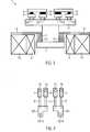
Die Aufgabe wird erfindungsgemäß gelöst durch die Merkmale des Anspruchs 1. Demnach liegt dann eine erfindungsgemäße Lösung der Aufgabe vor, wenn für den elektromagnetischen Antrieb des Ankers eine Vorladespule sowie eine zusätzlich oder unabhängig von der Vorladespule bestrombare Anzugsspule vorgesehen sind, wobei das Spulenjoch derart angeordnet ist, dass die durch das von der Vorladespule erzeugte Magnetfeld auf den Anker wirkende Magnetkraft bei gleicher Bestromung der Vorladespule in der Endstellung des Ankers größer ist als in der Zwischenstellung, wobei diese Magnetkraft in der Zwischenstellung des Ankers der Rückstellkraft entspricht und in der Endstellung des Ankers größer ist als die Rückstellkraft, und wobei die Vorladespule vorgesehen ist, um den Anker von der Ausgangslage in die Zwischenstellung zu bewegen sowie in der Endstellung zu halten, und ferner die Anzugsspule vorgesehen ist, um den Anker von der Zwischenstellung in die Endstellung zu bewegen. The object is achieved according to the invention by the features of
Die Erfindung bietet den Vorteil, dass der Anker kontrolliert in der Zwischenstellung gehalten werden kann, in welcher lediglich die Nebenkontakte nicht aber die Hauptkontakte geschlossen sind. Somit ist es möglich, über eine geeignete Messelektronik beispielsweise festzustellen, ob in dem durch die Nebenkontakte geschlossenen Stromkreis ein Kurzschluss vorliegt. Im Falle des Vorliegens eines Kurzschlusses kann der weitere Einschaltvorgang unterbrochen werden. Ein weiterer Vorteil der vorliegenden Erfindung ist, dass der Anker in der Endstellung, bei welcher sowohl die Nebenkontakte als auch die Hauptkontakte geschlossen sind, von der leistungsschwachen Vorladespule gehalten werden kann, so dass die Verlustleistung des Schaltschützes relativ gering ist. Beim Einschaltvorgang muss die Anzugsspule lediglich für kurze Zeit zugeschaltet werden. Die Anzugsspule ist in der Regel leistungsstärker ausgelegt, wird aber nur für kurze Zeit betrieben.The invention offers the advantage that the armature can be kept controlled in the intermediate position, in which only the secondary contacts are not closed but the main contacts. Thus, it is possible to determine via a suitable measuring electronics, for example, whether there is a short circuit in the circuit closed by the secondary contacts. In the case of a short circuit, the further switch-on can be interrupted. Another advantage of the present invention is that the armature in the end position, in which both the side contacts and the main contacts are closed, can be held by the low-power precharge coil, so that the power loss of the contactor is relatively low. When switching on the suit coil must be switched on only for a short time. The tightening coil is usually designed to be more powerful, but is only operated for a short time.
Weitere Ausgestaltungen der vorliegenden Erfindung sind Gegenstand der Unteransprüche.Further embodiments of the present invention are the subject of the dependent claims.
So ist in einer bevorzugten Ausführungsform der vorliegenden Erfindung die Anzugsspule der Vorladespule für den Antrieb des Ankers von der Zwischenstellung in die Endstellung zugeschaltet. Rein theoretisch wäre es auch möglich, die Vorladespule für den Antrieb des Ankers von der Zwischenstellung in die Endstellung auszuschalten und lediglich die Anzugsspule anzuschalten. In diesem Fall müsste die Anzugsspule jedoch leistungsstärker ausgelegt sein.Thus, in a preferred embodiment of the present invention, the tightening coil of the precharging coil for driving the armature is switched from the intermediate position to the end position. In theory, it would also be possible to switch off the precharging coil for driving the armature from the intermediate position to the end position and to switch on only the tightening coil. In this case, however, the tension coil would have to be designed to be more powerful.
In einer weiteren bevorzugten Ausführungsform der vorliegenden Erfindung sind Vorladespule und Anzugsspule konzentrisch zueinander angeordnet. Dadurch kann das von der Vorladespule erzeugte magnetische Feld von der Anzugsspule auf optimale Art und Weise verstärkt werden. Vorzugsweise umschließen Vorladespule und Anzugsspule zumindest einen Teil des Ankers. So kann eine sehr große magnetische Kraft auf dem Anker ausgeübt werden. Zudem erlaubt diese Anordnung eine platzsparende Bauweise.In a further preferred embodiment of the present invention, the precharging coil and the attraction coil are arranged concentrically with one another. Thereby, the magnetic field generated by the precharging coil can be amplified by the suiting coil in an optimum manner. Precharging coil and tightening coil preferably surround at least part of the armature. So a very large magnetic force can be exerted on the anchor. In addition, this arrangement allows a space-saving design.
In einer weiteren bevorzugten Ausführungsform der vorliegenden Erfindung sind Vorladespule und Anzugsspule übereinander gewickelt, wobei die Anzugsspule die äußere Wicklung darstellt. Somit wird eine äußerst kostengünstige und einfache Herstellung des Schaltschützes ermöglicht.In another preferred embodiment of the present invention, the precharging coil and the tightening coil are wound one over the other, the tightening coil being the outer winding. Thus, a very inexpensive and simple production of the contactor is made possible.
Wenn in einer weiteren bevorzugten Ausführungsform der vorliegenden Erfindung der ohmsche Widerstand der Anzugsspule kleiner ist als der ohmsche Widerstand der Vorladespule, so ist die Leistung der Anzugsspule und damit die von der Anzugsspule erzeugte magnetische Kraft auf den Anker so groß, dass ein schneller und sicherer Einschaltvorgang gewährleistet werden kann. Vorzugsweise ist die Anzugsspule dazu aus einem dickeren Draht gewickelt als die Vorladespule.In a further preferred embodiment of the present invention, when the ohmic resistance of the pickup coil is less than the ohmic resistance of the precharge coil, the power of the pickup coil, and hence the magnetic force generated by the pickup coil on the armature, is so great as to provide a quicker and safer turn on can be guaranteed. Preferably, the suit coil is wound from a thicker wire than the precharge coil.
In einer weiteren bevorzugten Ausführungsform der vorliegenden Erfindung umfassen die Mittel zur Rückstellung des Ankers in die Ausgangslage eine erste Feder, die zwischen einem ersten Federanschlag des Ankers und einem mit dem Gehäuse verbundenen zweiten Federanschlag angeordnet ist und in jeder Position des Ankers zwischen der Ausgangslage und der Endstellung eine Rückstellkraft auf den Anker ausübt. Die erste Feder gewährleistet, dass das Schaltschütz ausgeschaltet wird, sobald die Stromzufuhr der Spulen unterbrochen ist. Vorzugsweise umfassen die Mittel zur Rückstellung des Ankers in die Ausgangslage ferner eine zweite Feder, die kürzer ist als die erste Feder und ebenfalls zwischen dem ersten Federanschlag und dem zweiten Federanschlag angeordnet ist. Die zweite Feder übt dabei keine Rückstellkraft auf den Anker aus, wenn sich der Anker zwischen der Ausgangslage und einer Position nahe der Zwischenstellung befindet. Wenn sich der Anker zwischen dieser Position nahe der Zwischenstellung und der Endstellung befindet, wird von der zweiten Feder eine Rückstellkraft auf den Anker ausgeübt. Somit ist es auf einfache Art und Weise möglich, die Rückstellkraft auf den Anker nahe der Zwischenstellung stufenförmig zu erhöhen, so dass die Vorladespule nicht ausreicht, um den Anker von der Zwischenstellung weiter in die Endstellung zu bewegen. Vorzugsweise ist dabei die zweite Feder zudem härter als die erste Feder.In a further preferred embodiment of the present invention, the means for returning the armature to the starting position comprise a first spring, which is arranged between a first spring stop of the armature and a second spring stop connected to the housing and in any position of the armature between the starting position and the End position exerts a restoring force on the anchor. The first spring ensures that the contactor is switched off as soon as the power supply to the coils is interrupted. Preferably, the means for returning the armature to the starting position further comprise a second spring, which is shorter than the first spring and is also disposed between the first spring stop and the second spring stop. The second spring exerts no restoring force on the armature when the armature is between the starting position and a position near the intermediate position. When the armature is between this position near the intermediate position and the end position, a restoring force is exerted on the armature by the second spring. Thus, it is possible in a simple manner to increase the restoring force on the armature near the intermediate position stepwise, so that the precharging coil is not sufficient to move the armature from the intermediate position further into the end position. Preferably, the second spring is also harder than the first spring.
In einer weiteren bevorzugten Ausführungsform der vorliegenden Erfindung sind erste Feder und zweite Feder als Spiralfedern ausgeführt und konzentrisch zueinander angeordnet. Dies erlaubt einen einfachen Aufbau des erfindungsgemäßen Schaltschützes. In einer weiteren bevorzugten Ausführungsform der vorliegenden Erfindung sind ferner elektrische Widerstände mit Anschlüssen der Nebenkontakte verbunden, um die Stromstärke in einem über die Nebenkontakte geschlossenen Stromkreis zu begrenzen. Die Widerstände können dabei in das Gehäuse des Schaltschützes integriert sein. Auch ist es möglich, die Widerstände zusammen mit dem Schaltschütz in einem Stromkreis zu verschalten. Das Vorsehen der Widerstände erlaubt beispielsweise die Vorladung eines mit dem Schaltschütz verbundenen Kondensators.In a further preferred embodiment of the present invention, the first spring and the second spring are designed as spiral springs and arranged concentrically to one another. This allows a simple construction of the contactor according to the invention. In a further preferred embodiment In addition, in the present invention, electrical resistors are connected to terminals of the sub-contacts to limit the current in a closed circuit through the sub-contacts. The resistors can be integrated into the housing of the contactor. It is also possible to connect the resistors together with the contactor in a circuit. The provision of the resistors allows, for example, the precharging of a capacitor connected to the contactor.
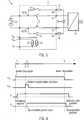
In einer weiteren besonders bevorzugten Ausführungsform der vorliegenden Erfindung ist ferner eine Elektronik zum Einschalten und Ausschalten von Vorladespule und Anzugsspule sowie zur Messung und Überwachung einer durch die Nebenkontakte fließenden Stromstärke vorgesehen. Vorzugsweise ist die Elektronik derart beschaffen, dass die Anzugsspule, wenn die beim Einschaltvorgang in der zweiten Schaltstellung von der Elektronik gemessene Stromstärke einen ersten Schwellwert unterschreitet, von der Elektronik für eine gewisse Zeitdauer der Vorladespule zugeschaltet wird, so dass der Anker von der Zwischenstellung in die Endstellung bewegt wird, wobei die Vorladespule, wenn die von der Elektronik gemessene Stromstärke in der zweiten Schaltstellung einen zweiten Schwellwert für eine gewisse Zeitdauer überschreitet, von der Elektronik abgeschaltet wird, so dass der Anker durch die Rückstellkraft in die Ausgangslage bewegt wird. Die Elektronik erlaubt somit die Erkennung eines Kurzschlusses, in dem vom Schaltschütz geschalteten Stromkreis und verhindert, dass die Hauptkontakte bei Vorliegen eines Kurzschlusses geschlossen werden.In a further particularly preferred embodiment of the present invention, an electronics for switching on and off of Vorladespule and suit coil and for measuring and monitoring a current flowing through the secondary contacts current is also provided. Preferably, the electronics are such that the tightening coil, if the current measured during the switch-on in the second switching position by the electronics falls below a first threshold, is switched by the electronics for a certain period of Vorladespule, so that the anchor from the intermediate position in the End position is moved, wherein the precharging coil, when the current measured by the electronics in the second switching position exceeds a second threshold for a certain period of time, is switched off by the electronics, so that the armature is moved by the restoring force to the starting position. The electronics thus allows the detection of a short circuit in the circuit switched by the contactor and prevents the main contacts are closed in the presence of a short circuit.
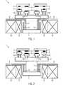
In einer weiteren bevorzugten Ausführungsform der vorliegenden Erfindung sind Hauptkontakte und Nebenkontakte im Wesentlichen nebeneinander in einer Ebene angeordnet, so dass sie senkrecht zur Bewegungsrichtung des Ankers ausgerichtet ist. Dies erlaubt eine äußerst kompakte Bauweise des Schaltschützes.In a further preferred embodiment of the present invention, main contacts and secondary contacts are arranged substantially side by side in a plane, so that it is aligned perpendicular to the direction of movement of the armature. This allows an extremely compact design of the contactor.
In einer weiteren bevorzugten Ausführungsform der vorliegenden Erfindung umfasst das Schaltschütz ferner einen Kontaktbrückenträger, auf dem die Hauptkontaktbrücken und Nebenkontaktbrücken angeordnet sind, wobei der Kontaktbrückenträger mit dem Anker verbunden ist. Vorzugsweise sind die Hauptkontaktbrücken und die Nebenkontaktbrücken dabei mittels Kontaktdruckfedern federnd auf dem Kontaktbrückenträger gelagert. Durch die Kontaktdruckfedern werden die Hauptkontaktbrücken in der Endstellung des Ankers gegen die festen Hauptkontakte, sowie die Nebenkontaktbrücken in der Zwischenstellung sowie Endstellung des Ankers gegen die festen Nebenkontakte gedrückt. Die entsprechenden Kontakte sind in der jeweiligen Stellung des Ankers dadurch fest und sicher geschlossen, so dass eine Öffnung der Kontakte durch externe mechanische Lasten wie beispielsweise beim Betrieb eines Fahrzeugs auftretende Vibrationen verhindert wird. Vorzugsweise sind die Kontaktdruckfedern der Nebenkontaktbrücken länger als die Kontaktdruckfedern der Hauptkontaktbrücken, wobei der Abstand zwischen Nebenkontakten und Nebenkontaktbrücken in der ersten Schaltstellung größer ist als der Abstand zwischen Hauptkontakten und Hauptkontaktbrücken. Somit kann auf einfache Art und Weise erreicht werden, dass die Nebenkontakte in der Zwischenstelle des Ankers geschlossen sind, ohne dass dabei die Hauptkontakte ebenfalls geschlossen werden.In a further preferred embodiment of the present invention, the contactor further comprises a contact bridge carrier, on which the main contact bridges and secondary contact bridges are arranged, wherein the contact bridge carrier is connected to the armature. Preferably, the main contact bridges and the sub-contact bridges are spring-mounted on the contact bridge carrier by means of contact pressure springs. By the contact pressure springs, the main contact bridges are pressed in the end position of the armature against the fixed main contacts, as well as the side contact bridges in the intermediate position and end position of the armature against the fixed side contacts. The corresponding contacts are thereby firmly and securely closed in the respective position of the armature, so that an opening of the contacts is prevented by external mechanical loads such as vibrations occurring during operation of a vehicle. Preferably, the contact pressure springs of the secondary contact bridges are longer than the contact pressure springs of the main contact bridges, wherein the distance between side contacts and side contact bridges in the first switching position is greater than the distance between the main contacts and main contact bridges. Thus, it can be achieved in a simple manner that the secondary contacts are closed in the intermediate position of the armature, without causing the main contacts are also closed.
In einer weiteren besonders bevorzugten Ausführungsform der vorliegenden Erfindung sind die Hauptkontakte und die Nebenkontakte im Bereich einer gemeinsamen Lichtbogenlöscheinrichtung angeordnet. Lichtbogen treten insbesondere beim Ausschalten, also beim öffnen der Kontakte, auf und können zum Verschweißen der Kontakte führen. Durch eine Lichtbogenlöscheinrichtung kann dieser Effekt vermieden werden, so dass die Lebensdauer des Schaltschützes heraufgesetzt wird. Durch eine gemeinsame Lichtbogenlöscheinrichtung für Hauptkontakte und Nebenkontakte wird dabei eine kompakte Bauweise erreicht. Die Lichtbogenlöscheinrichtung umfasst vorzugsweise einen Löschraum mit mehreren lamellenartig angeordneten Löschblechen. Dabei kann die Wirkung der Lichtbogenlöscheinrichtung verbessert werden, wenn der Löschraum mit einem Schutzgas gefüllt ist.In a further particularly preferred embodiment of the present invention, the main contacts and the secondary contacts are arranged in the region of a common arc-quenching device. Arc occur especially when you turn off, so when opening the contacts, and can lead to welding of the contacts. By an arc quenching device, this effect can be avoided, so that the life of the contactor is increased. Through a common arc quenching device for main contacts and secondary contacts while a compact design is achieved. The arc quenching device preferably comprises a quenching chamber with a plurality of lamellae-like quenching plates. In this case, the effect of the arc quenching device can be improved if the quenching chamber is filled with a protective gas.
In einer weiteren besonders bevorzugten Ausführungsform der vorliegenden Erfindung, ist das Schaltschütz zweipolig ausgeführt und umfasst vier Hauptkontakte sowie vier Nebenkontakte. Jeweils zwei dieser Kontakte werden dabei durch eine Kontaktbrücke geschlossen.In a further particularly preferred embodiment of the present invention, the contactor is bipolar and comprises four main contacts and four auxiliary contacts. Two of these contacts are closed by a contact bridge.
Im Folgenden wird ein Ausführungsbeispiel der vorliegenden Erfindung anhand von Zeichnungen näher erläutert.In the following, an embodiment of the present invention will be explained in more detail with reference to drawings.
Es zeigen:Show it:
Für die folgenden Ausführungen gilt, dass durch gleiche Bezugszeichen gleiche Teile bezeichnet werden.For the following explanations, the same reference numerals refer to identical parts.
Die
Wenn an die Vorladespule
Wird nun der Vorladespule
Es sei angemerkt, dass das erfindungsgemäße Schaltschütz auch bei Wechselspannungsapplikationen zum Einsatz kommen kann, beispielsweise wenn dort eine Vorladung vorgesehen ist. Das in den
ZITATE ENTHALTEN IN DER BESCHREIBUNG QUOTES INCLUDE IN THE DESCRIPTION
Diese Liste der vom Anmelder aufgeführten Dokumente wurde automatisiert erzeugt und ist ausschließlich zur besseren Information des Lesers aufgenommen. Die Liste ist nicht Bestandteil der deutschen Patent- bzw. Gebrauchsmusteranmeldung. Das DPMA übernimmt keinerlei Haftung für etwaige Fehler oder Auslassungen.This list of the documents listed by the applicant has been generated automatically and is included solely for the better information of the reader. The list is not part of the German patent or utility model application. The DPMA assumes no liability for any errors or omissions.
Zitierte PatentliteraturCited patent literature
- DE 3105117 A1[0003, 0003]DE 3105117 A1[0003, 0003]
- DE 10315243 B3[0003]DE 10315243 B3[0003]
Claims (21)
Translated fromGermanPriority Applications (5)
| Application Number | Priority Date | Filing Date | Title |
|---|---|---|---|
| DE102010032456ADE102010032456B4 (en) | 2010-07-28 | 2010-07-28 | Electric contactor |
| PCT/EP2011/002146WO2012013252A1 (en) | 2010-07-28 | 2011-04-28 | Electrical contactor |
| CN2011800336708ACN103038850A (en) | 2010-07-28 | 2011-04-28 | Electrical contactor |
| US13/812,830US20130181793A1 (en) | 2010-07-28 | 2011-04-28 | Electrical contactor |
| EP11716385.7AEP2599099A1 (en) | 2010-07-28 | 2011-04-28 | Electrical contactor |
Applications Claiming Priority (1)
| Application Number | Priority Date | Filing Date | Title |
|---|---|---|---|
| DE102010032456ADE102010032456B4 (en) | 2010-07-28 | 2010-07-28 | Electric contactor |
Publications (2)
| Publication Number | Publication Date |
|---|---|
| DE102010032456A1true DE102010032456A1 (en) | 2012-02-02 |
| DE102010032456B4 DE102010032456B4 (en) | 2012-11-29 |
Family
ID=44202059
Family Applications (1)
| Application Number | Title | Priority Date | Filing Date |
|---|---|---|---|
| DE102010032456AExpired - Fee RelatedDE102010032456B4 (en) | 2010-07-28 | 2010-07-28 | Electric contactor |
Country Status (5)
| Country | Link |
|---|---|
| US (1) | US20130181793A1 (en) |
| EP (1) | EP2599099A1 (en) |
| CN (1) | CN103038850A (en) |
| DE (1) | DE102010032456B4 (en) |
| WO (1) | WO2012013252A1 (en) |
Cited By (7)
| Publication number | Priority date | Publication date | Assignee | Title |
|---|---|---|---|---|
| EP2775502A1 (en)* | 2013-03-08 | 2014-09-10 | Siemens Aktiengesellschaft | Switching device for switching a capacitor |
| DE102014200681A1 (en) | 2014-01-16 | 2015-07-16 | Robert Bosch Gmbh | Switching device for switching high electrical currents and battery system with such a switching device |
| DE102014206511A1 (en) | 2014-04-04 | 2015-10-08 | Robert Bosch Gmbh | A method for monitoring the state of the contactor contacts of a controllable by means of an excitation coil contactor |
| EP2940704A1 (en)* | 2014-05-01 | 2015-11-04 | Johnson Electric S.A. | Improvements in electrical contact sets |
| EP2889891A4 (en)* | 2012-04-27 | 2016-07-27 | Fuji Elec Fa Components & Sys | ELECTROMAGNETIC SWITCH |
| US9653222B2 (en) | 2012-04-13 | 2017-05-16 | Fuji Electric Co., Ltd. | Contact device, and electromagnetic switch in which the contact device is used |
| DE102015119352B4 (en) | 2015-11-10 | 2018-06-07 | Lisa Dräxlmaier GmbH | ELECTROMECHANIC PROTECTION SWITCH |
Families Citing this family (13)
| Publication number | Priority date | Publication date | Assignee | Title |
|---|---|---|---|---|
| GB201200331D0 (en) | 2012-01-09 | 2012-02-22 | Dialight Europ Ltd | Improvements in switching contactors (II) |
| US9118335B2 (en) | 2012-09-16 | 2015-08-25 | Technische Universiteit Delft | High resolution millimeter wave digitally controlled oscillator with reconfigurable distributed metal capacitor passive resonators |
| DE102013215563A1 (en)* | 2013-08-07 | 2015-02-12 | Robert Bosch Gmbh | Pre-charging unit for battery interruption unit |
| GB201402560D0 (en)* | 2014-02-13 | 2014-04-02 | Johnson Electric Sa | Improvements in or relating to electrical contactors |
| JP6551339B2 (en)* | 2015-11-17 | 2019-07-31 | アンデン株式会社 | Electromagnetic relay |
| CN105914107B (en)* | 2016-06-22 | 2017-11-28 | 沈阳二一三控制电器制造有限公司 | A kind of contactor for connecting capacitive element |
| JP7014081B2 (en) | 2018-07-30 | 2022-02-01 | トヨタ自動車株式会社 | Charger |
| CN109256841A (en)* | 2018-11-14 | 2019-01-22 | 沈阳二三控制电器制造有限公司 | A kind of pre-charge system of electric car |
| JP7443842B2 (en)* | 2020-03-11 | 2024-03-06 | オムロン株式会社 | electromagnetic relay |
| CN111430169B (en)* | 2020-05-09 | 2022-06-10 | 浙江赫灵电气有限公司 | Asynchronous utensil switch of contact group break-make |
| DE102020214239A1 (en)* | 2020-11-12 | 2022-05-12 | Robert Bosch Gesellschaft mit beschränkter Haftung | Method of operating a contactor |
| CN113936963A (en)* | 2021-10-20 | 2022-01-14 | 沈阳二一三控制电器制造有限公司 | Contact assembly and direct current contactor |
| WO2025064497A1 (en)* | 2023-09-19 | 2025-03-27 | Sensata Technologies Inc. | Integrated precharge contactor |
Citations (2)
| Publication number | Priority date | Publication date | Assignee | Title |
|---|---|---|---|---|
| DE3105117A1 (en) | 1981-02-12 | 1982-08-19 | Siemens AG, 1000 Berlin und 8000 München | ELECTROMAGNETIC SWITCHGEAR |
| DE10315243B3 (en) | 2003-04-03 | 2004-08-26 | Siemens Ag | Electromechanical switching system for relays, switches and pushbuttons has main contact bridge providing contact path between pairs of fixed contacts |
Family Cites Families (2)
| Publication number | Priority date | Publication date | Assignee | Title |
|---|---|---|---|---|
| US6233131B1 (en)* | 1998-09-30 | 2001-05-15 | Rockwell Technologies, Llc | Electromagnetic operator for an electrical contactor and method for controlling same |
| JP3770081B2 (en)* | 2000-12-01 | 2006-04-26 | 株式会社デンソー | Magnetic switch for starter |
- 2010
- 2010-07-28DEDE102010032456Apatent/DE102010032456B4/ennot_activeExpired - Fee Related
- 2011
- 2011-04-28CNCN2011800336708Apatent/CN103038850A/enactivePending
- 2011-04-28EPEP11716385.7Apatent/EP2599099A1/ennot_activeWithdrawn
- 2011-04-28USUS13/812,830patent/US20130181793A1/ennot_activeAbandoned
- 2011-04-28WOPCT/EP2011/002146patent/WO2012013252A1/enactiveApplication Filing
Patent Citations (2)
| Publication number | Priority date | Publication date | Assignee | Title |
|---|---|---|---|---|
| DE3105117A1 (en) | 1981-02-12 | 1982-08-19 | Siemens AG, 1000 Berlin und 8000 München | ELECTROMAGNETIC SWITCHGEAR |
| DE10315243B3 (en) | 2003-04-03 | 2004-08-26 | Siemens Ag | Electromechanical switching system for relays, switches and pushbuttons has main contact bridge providing contact path between pairs of fixed contacts |
Cited By (13)
| Publication number | Priority date | Publication date | Assignee | Title |
|---|---|---|---|---|
| US9653222B2 (en) | 2012-04-13 | 2017-05-16 | Fuji Electric Co., Ltd. | Contact device, and electromagnetic switch in which the contact device is used |
| US9673008B2 (en) | 2012-04-27 | 2017-06-06 | Fuji Electric Co., Ltd. | Electromagnetic switch |
| EP2889891A4 (en)* | 2012-04-27 | 2016-07-27 | Fuji Elec Fa Components & Sys | ELECTROMAGNETIC SWITCH |
| EP2775502A1 (en)* | 2013-03-08 | 2014-09-10 | Siemens Aktiengesellschaft | Switching device for switching a capacitor |
| WO2015106975A1 (en) | 2014-01-16 | 2015-07-23 | Robert Bosch Gmbh | Switching device for switching high electric currents, and battery system comprising such a switching device |
| DE102014200681A1 (en) | 2014-01-16 | 2015-07-16 | Robert Bosch Gmbh | Switching device for switching high electrical currents and battery system with such a switching device |
| DE102014206511A1 (en) | 2014-04-04 | 2015-10-08 | Robert Bosch Gmbh | A method for monitoring the state of the contactor contacts of a controllable by means of an excitation coil contactor |
| US10242828B2 (en) | 2014-04-04 | 2019-03-26 | Robert Bosch Gmbh | Method for monitoring the state of the earthing contacts of a contactor controllable by means of an exciter coil |
| EP2940704A1 (en)* | 2014-05-01 | 2015-11-04 | Johnson Electric S.A. | Improvements in electrical contact sets |
| KR20150126302A (en)* | 2014-05-01 | 2015-11-11 | 존슨 일렉트릭 에스.에이. | Improvements in electrical contact sets |
| US9484172B2 (en) | 2014-05-01 | 2016-11-01 | Johnson Electric S.A. | Electrical contact sets |
| KR102412668B1 (en)* | 2014-05-01 | 2022-06-22 | 존슨 일렉트릭 인터내셔널 아게 | Improvements in electrical contact sets |
| DE102015119352B4 (en) | 2015-11-10 | 2018-06-07 | Lisa Dräxlmaier GmbH | ELECTROMECHANIC PROTECTION SWITCH |
Also Published As
| Publication number | Publication date |
|---|---|
| DE102010032456B4 (en) | 2012-11-29 |
| US20130181793A1 (en) | 2013-07-18 |
| WO2012013252A1 (en) | 2012-02-02 |
| CN103038850A (en) | 2013-04-10 |
| EP2599099A1 (en) | 2013-06-05 |
Similar Documents
| Publication | Publication Date | Title |
|---|---|---|
| DE102010032456B4 (en) | Electric contactor | |
| DE102015000796A1 (en) | Switching device with permanent magnetic arc extinguishing | |
| DE102011122439A1 (en) | Device and method for switching electrical load circuits | |
| EP2864995A1 (en) | Switching device with electromagnetic latching mechanism | |
| EP2775502B1 (en) | Switching device for switching a capacitor | |
| WO2000079672A1 (en) | Magnetic linear drive | |
| DE102010018738A1 (en) | Bistable relay | |
| DE102011114997A1 (en) | Contact arrangement for contactor that is utilized as safety switching elements in motor vehicle, has closing device controlled by control device that supplies current to closing device, such that force is cyclically exerted on contact | |
| WO2003017308A1 (en) | Electromagnet arrangement for a switch | |
| EP2313905B1 (en) | Switching device | |
| WO2015185371A1 (en) | Relay | |
| DE102014211735A1 (en) | Electromechanical relay | |
| DE102012005031A1 (en) | Service switching device e.g. fault current limiter, has contact apparatuses which are provided in interior of pressure-resistant chamber so that pressure inside the pressure-tight chamber is raised to extinguish the generated arc | |
| DE102012208122B4 (en) | Switching contactor for direct current motor for window lifter, has coil core designed as permanent magnet, and control unit adjusting direct voltages, where cut-off current is directed opposite to exciting current | |
| DE102015202221A1 (en) | Automatic short-circuit disconnecting device | |
| DE102013222198A1 (en) | triggering device | |
| DE102018206054B4 (en) | Contactor | |
| DE3689468T2 (en) | Electric remote switches. | |
| DE19744396A1 (en) | Bistable relay for heavy current range | |
| DE102008029188B4 (en) | Submersible armature assembly with different trip ranges | |
| DE415503C (en) | Electric lighting systems, in particular for motor vehicles | |
| DE102024200463A1 (en) | SAFETY SWITCHING DEVICE AND OPERATING METHOD THEREFOR | |
| DE2552461A1 (en) | Electromagnetic electric contact system - has electromagnet whose core is fixed in housing and armature is connected to movable contact | |
| WO2005088659A2 (en) | Breaker in particular a safety breaker for a battery/loom connection | |
| DE102012219075A1 (en) | Relay e.g. battery circuit breaker, for use in motor car, has load terminals arranged parallel to axles, so that magnetic field generated by load current is arranged vertically another magnetic field generated by coil |
Legal Events
| Date | Code | Title | Description |
|---|---|---|---|
| R016 | Response to examination communication | ||
| R018 | Grant decision by examination section/examining division | ||
| R020 | Patent grant now final | Effective date:20130301 | |
| R119 | Application deemed withdrawn, or ip right lapsed, due to non-payment of renewal fee |