DE102010025303A1 - Surgical retractor for expansion and retention of e.g. organ walls of patient, has retraction element connected over spring elements of base frame, where base frame is designed as radially outwardly acting cup expander spring - Google Patents
Surgical retractor for expansion and retention of e.g. organ walls of patient, has retraction element connected over spring elements of base frame, where base frame is designed as radially outwardly acting cup expander springDownload PDFInfo
- Publication number
- DE102010025303A1 DE102010025303A1DE102010025303ADE102010025303ADE102010025303A1DE 102010025303 A1DE102010025303 A1DE 102010025303A1DE 102010025303 ADE102010025303 ADE 102010025303ADE 102010025303 ADE102010025303 ADE 102010025303ADE 102010025303 A1DE102010025303 A1DE 102010025303A1
- Authority
- DE
- Germany
- Prior art keywords
- base frame
- retraction
- retractor
- elements
- surgical retractor
- Prior art date
- Legal status (The legal status is an assumption and is not a legal conclusion. Google has not performed a legal analysis and makes no representation as to the accuracy of the status listed.)
- Withdrawn
Links
- 210000000056organAnatomy0.000titleclaimsdescription16
- 230000014759maintenance of locationEffects0.000titledescription3
- 239000012858resilient materialSubstances0.000claimsabstractdescription4
- 239000000463materialSubstances0.000claimsdescription21
- 230000007480spreadingEffects0.000claimsdescription10
- 210000004204blood vesselAnatomy0.000claimsdescription8
- 230000007704transitionEffects0.000claimsdescription7
- 229910000831SteelInorganic materials0.000claimsdescription4
- 210000000078clawAnatomy0.000claimsdescription4
- 238000003780insertionMethods0.000claimsdescription4
- 230000037431insertionEffects0.000claimsdescription4
- 239000010959steelSubstances0.000claimsdescription4
- RTAQQCXQSZGOHL-UHFFFAOYSA-NTitaniumChemical compound[Ti]RTAQQCXQSZGOHL-UHFFFAOYSA-N0.000claimsdescription3
- 229910052782aluminiumInorganic materials0.000claimsdescription3
- XAGFODPZIPBFFR-UHFFFAOYSA-NaluminiumChemical compound[Al]XAGFODPZIPBFFR-UHFFFAOYSA-N0.000claimsdescription3
- 229910052719titaniumInorganic materials0.000claimsdescription3
- 239000010936titaniumSubstances0.000claimsdescription3
- 230000007797corrosionEffects0.000claimsdescription2
- 238000005260corrosionMethods0.000claimsdescription2
- 230000003446memory effectEffects0.000claimsdescription2
- 229910001000nickel titaniumInorganic materials0.000claimsdescription2
- HLXZNVUGXRDIFK-UHFFFAOYSA-Nnickel titaniumChemical compound[Ti].[Ti].[Ti].[Ti].[Ti].[Ti].[Ti].[Ti].[Ti].[Ti].[Ti].[Ni].[Ni].[Ni].[Ni].[Ni].[Ni].[Ni].[Ni].[Ni].[Ni].[Ni].[Ni].[Ni].[Ni]HLXZNVUGXRDIFK-UHFFFAOYSA-N0.000claimsdescription2
- 229910001285shape-memory alloyInorganic materials0.000claimsdescription2
- 210000001519tissueAnatomy0.000description17
- 238000001356surgical procedureMethods0.000description14
- 210000000709aortaAnatomy0.000description13
- 210000001765aortic valveAnatomy0.000description13
- 210000002216heartAnatomy0.000description11
- 210000000038chestAnatomy0.000description5
- 210000001562sternumAnatomy0.000description4
- 210000002376aorta thoracicAnatomy0.000description3
- 210000002168brachiocephalic trunkAnatomy0.000description3
- 230000006835compressionEffects0.000description3
- 238000007906compressionMethods0.000description3
- 210000003238esophagusAnatomy0.000description3
- 210000003709heart valveAnatomy0.000description3
- 206010002091AnaesthesiaDiseases0.000description2
- 241001631457CannulaSpecies0.000description2
- 230000037005anaesthesiaEffects0.000description2
- 239000008280bloodSubstances0.000description2
- 210000004369bloodAnatomy0.000description2
- 230000001101cardioplegic effectEffects0.000description2
- 230000002612cardiopulmonary effectEffects0.000description2
- 230000000694effectsEffects0.000description2
- 230000002496gastric effectEffects0.000description2
- 210000005003heart tissueAnatomy0.000description2
- 238000011065in-situ storageMethods0.000description2
- 230000003993interactionEffects0.000description2
- 238000000034methodMethods0.000description2
- 210000003516pericardiumAnatomy0.000description2
- 210000003102pulmonary valveAnatomy0.000description2
- 230000008439repair processEffects0.000description2
- 210000005241right ventricleAnatomy0.000description2
- 210000003291sinus of valsalvaAnatomy0.000description2
- 238000007631vascular surgeryMethods0.000description2
- BUHVIAUBTBOHAG-FOYDDCNASA-N(2r,3r,4s,5r)-2-[6-[[2-(3,5-dimethoxyphenyl)-2-(2-methylphenyl)ethyl]amino]purin-9-yl]-5-(hydroxymethyl)oxolane-3,4-diolChemical compoundCOC1=CC(OC)=CC(C(CNC=2C=3N=CN(C=3N=CN=2)[C@H]2[C@@H]([C@H](O)[C@@H](CO)O2)O)C=2C(=CC=CC=2)C)=C1BUHVIAUBTBOHAG-FOYDDCNASA-N0.000description1
- 208000034656ContusionsDiseases0.000description1
- 241001465754MetazoaSpecies0.000description1
- 208000031481Pathologic ConstrictionDiseases0.000description1
- 229910000639Spring steelInorganic materials0.000description1
- 238000012084abdominal surgeryMethods0.000description1
- 230000008901benefitEffects0.000description1
- 230000015572biosynthetic processEffects0.000description1
- 238000013132cardiothoracic surgeryMethods0.000description1
- 238000000576coating methodMethods0.000description1
- 210000004351coronary vesselAnatomy0.000description1
- 210000005069earsAnatomy0.000description1
- 238000004049embossingMethods0.000description1
- 210000003811fingerAnatomy0.000description1
- 230000006870functionEffects0.000description1
- 210000000936intestineAnatomy0.000description1
- 230000003902lesionEffects0.000description1
- 230000007246mechanismEffects0.000description1
- 229910052751metalInorganic materials0.000description1
- 239000002184metalSubstances0.000description1
- 230000036316preloadEffects0.000description1
- 230000002040relaxant effectEffects0.000description1
- 239000010935stainless steelSubstances0.000description1
- 229910001220stainless steelInorganic materials0.000description1
- 230000036262stenosisEffects0.000description1
- 208000037804stenosisDiseases0.000description1
- 210000002784stomachAnatomy0.000description1
- 210000003813thumbAnatomy0.000description1
- 230000000451tissue damageEffects0.000description1
- 231100000827tissue damageToxicity0.000description1
- 210000003437tracheaAnatomy0.000description1
- 210000000591tricuspid valveAnatomy0.000description1
- 230000002792vascularEffects0.000description1
Images


Classifications
- A—HUMAN NECESSITIES
- A61—MEDICAL OR VETERINARY SCIENCE; HYGIENE
- A61B—DIAGNOSIS; SURGERY; IDENTIFICATION
- A61B17/00—Surgical instruments, devices or methods
- A61B17/02—Surgical instruments, devices or methods for holding wounds open, e.g. retractors; Tractors
- A—HUMAN NECESSITIES
- A61—MEDICAL OR VETERINARY SCIENCE; HYGIENE
- A61B—DIAGNOSIS; SURGERY; IDENTIFICATION
- A61B17/00—Surgical instruments, devices or methods
- A61B17/02—Surgical instruments, devices or methods for holding wounds open, e.g. retractors; Tractors
- A61B17/0293—Surgical instruments, devices or methods for holding wounds open, e.g. retractors; Tractors with ring member to support retractor elements
- A—HUMAN NECESSITIES
- A61—MEDICAL OR VETERINARY SCIENCE; HYGIENE
- A61B—DIAGNOSIS; SURGERY; IDENTIFICATION
- A61B17/00—Surgical instruments, devices or methods
- A61B17/02—Surgical instruments, devices or methods for holding wounds open, e.g. retractors; Tractors
- A61B2017/0237—Surgical instruments, devices or methods for holding wounds open, e.g. retractors; Tractors for heart surgery
Landscapes
- Health & Medical Sciences (AREA)
- Life Sciences & Earth Sciences (AREA)
- Surgery (AREA)
- Heart & Thoracic Surgery (AREA)
- Engineering & Computer Science (AREA)
- Biomedical Technology (AREA)
- Nuclear Medicine, Radiotherapy & Molecular Imaging (AREA)
- Medical Informatics (AREA)
- Molecular Biology (AREA)
- Animal Behavior & Ethology (AREA)
- General Health & Medical Sciences (AREA)
- Public Health (AREA)
- Veterinary Medicine (AREA)
- Surgical Instruments (AREA)
Abstract
Description
Translated fromGermanDie Erfindung betrifft einen chirurgischen Retraktor zum Aufspreizen und Halten von Gewebe, insbesondere von Blutgefäßwänden und/oder Organwänden, sowie ein chirurgisches Hilfsmittel zum Einsetzen und Entfernen des chirurgischen Retraktors.The invention relates to a surgical retractor for spreading and holding tissue, in particular blood vessel walls and / or organ walls, as well as a surgical aid for inserting and removing the surgical retractor.
Chirurgische Retraktoren werden bei operativen Eingriffen eingesetzt, um eine möglichst großzügige Sicht und einen optimalen Zugriff auf das Operationsgebiet zu ermöglichen.Surgical retractors are used in surgical procedures to provide the greatest possible visibility and access to the surgical site.
Je nach Art der Operation werden unterschiedliche Retraktoren verwendet. So gibt es unter anderem spezielle Retraktoren für die Abdominalchirurgie, für die Neurochirurgie usw.Depending on the type of surgery different retractors are used. There are special retractors for abdominal surgery, neurosurgery, etc.
In der Herz-Thorax-Chirurgie sind Retraktoren zum Retrahieren der unterschiedlichsten Strukturen bekannt, vom Spreizen des Brustkorbes bis hin zum Halten von Herzklappen bei minimal-invasiver Operationstechnik.In cardiothoracic surgery, retractors are known for retracting a variety of structures, from spreading the chest to holding heart valves with minimally invasive surgical technique.
Herzklappen wirken als Ventile und verhindern in der Entspannungsphase des Herzens einen unerwünschten Rückstrom des Blutes. Zwischen Vorhof und Kammer sind diese als Segelklappen ausgebildet (Biskuspidalklappe und Tricuspidalklappe), zwischen Kammer und Ausstromgefäß sind Taschenklappen vorhanden (Aorten- und Pulmonalklappe).Heart valves act as valves and prevent in the relaxation phase of the heart an undesirable reverse flow of the blood. Between forecourt and chamber these are designed as sail flaps (biscuspid valve and tricuspid valve), between the chamber and the outflow vessel pocket flaps are present (aortic and pulmonary valve).
An den Klappen kann es unter anderem zu Verengungen (Stenosen) aber auch zu Schlussunfähigkeiten (Insuffizienzen) kommen, die eine Operation notwendig machen.Amongst other things, the valves can lead to narrowing (stenosis) as well as inability to contract (insufficiency), which necessitates surgery.
Zur Zeit werden solche Operationen hauptsächlich am offenen Herzen durchgeführt. Die konventionelle Prozedur für eine Operation an der Aortenklappe beginnt mit dem Anästhesie des Patienten. Die Inzision erfolgt longitudinal über dem Sternum, das seinerseits longitudinal eröffnet wird. Ein Thorax-Spreizer wird so platziert, dass der Brustraum zugänglich wird. Das Gewebe um das Herz herum wird präpariert, so dass das Perikard eröffnet werden kann. Über Aorta und rechter Herzkammer wird ein kardiopulmonaler Bypass eingerichtet und der Patient an eine Herz-Lungen-Maschine angeschlossen. Die thorakale Aorta wird zwischen dem Abgang des Truncus brachiocephalicus und den Koronarostien abgeklemmt, das Herz über die Zufuhr von Kardioplegika arretiert und die Aorta eröffnet. Nach Reparatur oder Ersatz der Aortenklappe wird die in das Herz eingedrungene Luft entfernt und die Aorta durch Naht geschlossen. Die Abklemmung wird entfernt und der Patient von der Herz-Lungen-Maschine entwöhnt. Nach dem Entfernen der Bypass-Kanülen wird das Sternum verdrahtet und das durchtrennte Gewebe verschlossen.At present such operations are carried out mainly at the open heart. The conventional procedure for aortic valve surgery begins with the anesthesia of the patient. The incision is made longitudinally over the sternum, which in turn opens longitudinally. A thorax spreader is placed so that the chest becomes accessible. The tissue around the heart is prepared so that the pericardium can be opened. A cardiopulmonary bypass is established through the aorta and right ventricle, and the patient is connected to a heart-lung machine. The thoracic aorta is clamped between the exit of the brachiocephalic trunk and the coronary ostia, the heart arrested by the supply of cardioplegics and the aorta is opened. After repair or replacement of the aortic valve, the air that has entered the heart is removed and the aorta is closed by suturing. The clamping is removed and the patient weaned off the heart-lung machine. After removing the bypass cannulas, the sternum is wired and the severed tissue is sealed.
Bei solchen Operationen werden Retraktoren u. a. zum Offenhalten der Inzisionsstelle eingesetzt. So ist aus der
Andere Retraktoren in Form einer Harke werden ohne zusätzliche Mechanik manuell bedient bzw. an einem Rahmen befestigt und dienen zum individuellen Zurückhalten von vorfallendem Gewebe im Operationsgebiet.Other retractors in the form of a rake are operated manually or attached to a frame without additional mechanics and are used for individual retention of falling tissue in the operating area.
So ist z. B. aus der
Aufgabe der vorliegenden Erfindung ist es, die Nachteile im Stand der Technik zu überwinden, insbesondere, einen selbsthaltenden chirurgischen Retraktor bereitzustellen, der an transversal eröffneten Gefäßen oder anderen rohrförmigen Organen eingesetzt werden kann.The object of the present invention is to overcome the disadvantages of the prior art, in particular to provide a self-retaining surgical retractor that can be used on transversely opened vessels or other tubular organs.
Gelöst wird die Aufgabe durch einen chirurgischen Retraktor zum Aufspreizen und Halten von Gewebe, insbesondere von Blutgefäßwänden und/oder Organwänden, mit einem Grundrahmen und an dem Grundrahmen angeordneten Retraktionselementen, wobei der Grundrahmen aus einem federnden Material gebildet ist und der Grundrahmen eine Fläche aufspannt, aus der um eine frei Mitte herum angeordnete Retraktionselemente abgewinkelt sind, und der Grundrahmen als radial nach außen wirkende Spreizfeder ausgebildet ist.The object is achieved by a surgical retractor for spreading and holding tissue, in particular blood vessel walls and / or organ walls, with a base frame and arranged on the base frame retraction elements, wherein the base frame is formed of a resilient material and the base frame spans a surface from the angled around a free center around retraction elements are angled, and the base frame is designed as a radially outwardly acting spreading spring.
Retraktionselemente im Sinne dieser Erfindung sind Teile des chirurgischen Retraktors, die Gewebe zurückhalten können und die dazu dienen, an Gewebebereichen (flächig) anzugreifen und diese an einer gewünschten Position zu halten.Retraction elements in the sense of this invention are parts of the surgical retractor which can restrain tissue and which serve to engage tissue areas (areally) and to hold them in a desired position.
Der chirurgische Retraktor kann aus jedem beliebigen federnden Material angefertigt werden. Der Fachmann kann hierfür aus ihm bekannten Materialien auswählen. Vorzugsweise besteht das Instrument aus korrosionsbeständigem (rostfreien) Federdraht, weiter vorzugsweise mit Memory-Effekt, aus Nitinol oder einer anderen Formgedächtnis-Legierung oder aus einer Kombination dieser Materialien mit Stahl, Titan, Aluminium oder Kunststoff. Die Festigkeit des Retraktors muss so vorgesehen werden, dass er in sich formstabil ist. Einzelne Teile des Retraktors, z. B. die Retraktionselemente oder die Federelemente des Grundrahmens, aber auch der gesamte Retraktor können Überzüge aus einem der vorgenannten Materialien, vorzugsweise aus Kunststoff, aufweisen.The surgical retractor can be made from any springy material. The skilled person can select from known materials for this purpose. Preferably, the instrument consists of corrosion resistant (stainless) spring wire, more preferably memory effect, nitinol or other shape memory alloy or a combination of these materials with steel, titanium, aluminum or plastic. The The strength of the retractor must be such that it is inherently dimensionally stable. Individual parts of the retractor, z. As the retraction or the spring elements of the base frame, but also the entire retractor can coatings of any of the aforementioned materials, preferably made of plastic, have.
Die vom Grundrahmen aufgespannte Fläche ist eine Fläche, in deren Ebene der Grundrahmen bzw. die einzelnen Federelemente des Grundrahmens liegen.The surface spanned by the base frame is a surface in the plane of the base frame or the individual spring elements of the base frame lie.
Die vom Grundrahmen aufgespannte Fläche befindet sich außerhalb bzw. am Rande des Retraktionsgebietes. Zum Aufbau einer Vorspannung wird der Rahmen in der durch ihn aufgespannten Fläche radial nach innen gedrückt. Hierzu wird vorzugsweise das nachfolgend noch näher erläuterte Hilfsmittel verwendet; die Vorspannung kann jedoch auch manuell durch Zusammendrücken des Rahmens aufgebracht werden. Durch das Zusammendrücken des Rahmens wird eine radial nach außen gerichtete Rückstellkraft erzeugt, die sich beim Entspannen des vorgespannten Grundrahmens entfaltet. Mit Hilfe der Rückstellkraft werden auch die aus der durch den Grundrahmen aufgespannten Fläche abgewinkelten Retraktionselemente radial nach außen gedrückt und greifen dabei an einem Gewebe, beispielsweise einem Gefäß oder Hohlorgan von innen an, drücken es radial nach außen und halten Gefäß bzw. Lumen so offen.The area spanned by the base frame is located outside or at the edge of the retraction area. To build up a bias of the frame is pressed in the plane defined by him surface radially inward. For this purpose, preferably the aid explained in more detail below is used; However, the bias can also be applied manually by squeezing the frame. By compressing the frame a radially outward restoring force is generated, which unfolds when relaxing the prestressed base frame. With the help of the restoring force, the retraction elements angled away from the surface spanned by the base frame are also pressed radially outward, thereby engaging a tissue, for example a vessel or hollow organ, from the inside, pushing it radially outward and keeping the vessel or lumen open.
Die Erfindung eignet sich für jegliche Geweberetraktion, die ein Aufspreizen und/oder Halten von Gewebe an bestehenden oder durch einen operativen Eingriff geschaffenen Öffnungen bewirken soll, beispielsweise für Eingriffe an Blutgefässen, insbesondere für Eingriffe an den Taschenklappen (Aorten- und Pulmonalklappe). Durch den erfindungsgemäßen Retraktor kann eine umfassende Exposition dieser Klappen erfolgen. Es wird vermieden, dass die Aortenwurzel gezerrt wird. Die Retraktion bleibt während der Operation ohne zusätzlichen Manipulator stabil. Es wird vermieden, dass der Retraktor während der Operation repositioniert werden muss.The invention is suitable for any tissue retraction intended to cause spreading and / or retention of tissue on existing or surgically created openings, for example, for interventions on blood vessels, in particular for pocket flap surgery (aortic and pulmonary valve). Through the retractor according to the invention, a comprehensive exposure of these valves can take place. It is avoided that the aortic root is dragged. The retraction remains stable during the operation without additional manipulator. It is avoided that the retractor must be repositioned during surgery.
Generell kann der Retraktor an jeglichen rohrförmigen Organen, die während einer Operation transversal eröffnet werden müssen oder generell an deren natürlichen Enden, angewendet werden. Beispielsweise kann der erfindungsgemäße Retraktor auch bei Eingriffen an der Speiseröhre oder im Magen-Darm Bereich eingesetzt werden.In general, the retractor can be applied to any tubular organs that need to be opened transversely during surgery or generally at their natural ends. For example, the retractor according to the invention can also be used in interventions on the esophagus or in the gastrointestinal area.
Auch kann der Retraktor so vorgesehen werden, dass er zur Retraktion von Gewebe einer eröffneten Körperwand bei operativen Eingriffen eingesetzt werden kann.Also, the retractor can be provided so that it can be used for retraction of tissue of an opened body wall in surgical procedures.
Ein besonderer Vorteil des erfindungsgemäßen Retraktors liegt in seinem geringen Gewicht und in seinem einfachen Aufbau, wodurch der Retraktor sowohl leicht handzuhaben als auch zu reinigen ist.A particular advantage of the retractor according to the invention lies in its low weight and in its simple structure, whereby the retractor is both easy to handle and to clean.
Besonders vorteilhaft ist der Retraktor für den Einsatz an der transversal eröffneten thorakalen Aorta bei Eingriffen an der Aortenklappe. In der Aortenwurzel sind oberhalb (distal) der Taschenklappe drei Ausbuchtungen (Sinus) vorhanden, die ohne den Gegendruck der Blutsäule während des Eingriffs kollabieren und damit die Sicht und den Zugang zur Aortenklappe erschweren. Durch den erfindungsgemäßen Retraktor kann eine gleichzeitige und symmetrische Retraktion aller drei Aortensinus (von rechtem, linken und posteriorem) erfolgen. Sicht und Zugang zur Aortenklappe sind frei und diese kann repariert bzw. ersetzt werden. Die physiologische Form des aufgrund der Operationstechnik kollabierten rohrförmigen Organs wird wiederherstellt.The retractor is particularly advantageous for use on the transversely opened thoracic aorta during interventions on the aortic valve. In the aortic root above (distal) of the pocket flap three bulges (sinus) are present, which collapse without the back pressure of the blood column during the procedure, thus complicating the view and access to the aortic valve. By the retractor according to the invention, a simultaneous and symmetrical retraction of all three aortic sinus (from the right, left and posterior) can be done. View and access to the aortic valve are free and this can be repaired or replaced. The physiological form of the tubular organ collapsed due to the surgical technique is restored.
Vorzugsweise weist der Grundrahmen schlaufenförmige Federelemente auf, die kleeblattartig um die freie Mitte herum angeordnet sind. Die freie Mitte ist der Bereich, der in den Ausführungsbeispielen des Retraktors jeweils dem Lumen des rohrförmigen Organs im nicht kollabierten Zustand entspricht.Preferably, the base frame has loop-shaped spring elements which are arranged like a cloverleaf around the free center. The free center is the area corresponding in each case to the lumen of the tubular organ in the non-collapsed state in the exemplary embodiments of the retractor.
Die mehreren (zwei bis sechs) schlaufenförmigen Federelemente bestehen aus dünnem, biegsamen Material, das im Querschnitt rund, flach oder mehrkantig ausgebildet sein kann.The plurality (two to six) loop-shaped spring elements are made of thin, flexible material, which may be round, flat or polygonal in cross-section.
Die schlaufenförmigen Federelemente selbst können rund, oval, oder mehreckig (zwei- bis sechseckig) ausgebildet sein. Wenn Ecken am Rahmen vorhanden sind, dann sind diese vorzugsweise abgerundet, um Gewebeverletzungen zu vermeiden. Die verschiedenen schlaufenförmigen Federelemente in Form von „Ohren” sind nicht in sich geschlossen.The loop-shaped spring elements themselves can be round, oval or polygonal (two- to hexagonal). If there are corners on the frame, these are preferably rounded to avoid tissue damage. The various loop-shaped spring elements in the form of "ears" are not self-contained.
Für spezielle Anwendungen können die kleeblattartig um die freie Mitte herum angeordneten schlaufenförmige Federelemente flächig (als Fläche) ausgebildet oder bespannt sein. Beispielsweise kann für die schlaufenförmigen Federelemente eine elastische Kunststoffbespannung vorgesehen sein.For special applications, the cloverleaf-like around the free center arranged around loop-shaped spring elements can be flat (as a surface) formed or covered. For example, may be provided for the loop-shaped spring elements an elastic plastic covering.
Weiter vorzugsweise sind die Retraktionselemente in Form geschlossener Blades (Blätter), als Drahthaken oder als U-förmige Drahtschlaufen mit oder ohne Querstege ausgebildet.Further preferably, the retraction elements in the form of closed blades (leaves), designed as a wire hook or U-shaped wire loops with or without crossbars.
Die Retraktionselemente bestehen daher vorzugsweise aus Draht oder Blech, in besonders vorteilhafter Ausführung aus Edelstahl.The retraction elements therefore preferably consist of wire or sheet metal, in a particularly advantageous embodiment of stainless steel.
Vorzugsweise sind die Retraktionselemente über die schlaufenartigen Federelemente des Grundrahmens verbunden. In anderen Ausführungen können mehrere Retraktionselemente benachbart vorliegen und über Stege voneinander beabstandet sein.Preferably, the retraction elements are connected via the loop-like spring elements of the base frame. In other versions Several retraction elements may be adjacent and spaced apart by webs.
Vorteilhafterweise entspricht die Anzahl der Retraktionselemente genau der Anzahl der schlaufenförmigen Federelemente des Grundrahmens. Für besondere Anwendungen kann die Zahl der schlaufenförmigen Federelemente kleiner oder größer als die der Retraktionselemente sein. Die Anzahl an Federelementen bzw. an Retraktionselementen beträgt mindestens 2 und höchstens 6, so dass die Gesamtzahl an Federelementen und Retraktionselementen zusammen mindestens 4 und höchstens 12 beträgt.Advantageously, the number of retraction elements corresponds exactly to the number of loop-shaped spring elements of the base frame. For special applications, the number of loop-shaped spring elements may be smaller or larger than that of the retraction elements. The number of spring elements or retraction elements is at least 2 and at most 6, so that the total number of spring elements and retraction elements together is at least 4 and at most 12.
Weiter vorzugsweise bestehen die Federelemente im Übergang zu den Retraktionselementen aus bistabilem Material. Dabei bestimmt der Fachmann den genauen Bereich, in dem der Retraktor aus bistabilem Material besteht. Unter einem bistabilen Material wir ein solches verstanden, das in zwei Zuständen stabil ist. Bei Krafteinwirkung auf die eine Konformationen springt diese ab Überschreiten einer Grenzkraft in die andere Konformation um. Dieser zweite stabile Zustand kann durch erneute Krafteinwirkung wieder in den ersten stabilen Zustand überführt werden. Bistabilität kann z. B. durch Prägung des Materials erzielt werden. In der bistabilen Ausführung kann der Retraktor im beschriebenen Übergang zwei Konformationen annehmen.Further preferably, the spring elements in the transition to the retraction of bistable material. The skilled person will determine the exact area in which the retractor consists of bistable material. By a bistable material we mean one that is stable in two states. When force is applied to one of the conformations, it will jump to the other conformation when one limit force is exceeded. This second stable state can be converted by renewed force back into the first stable state. Bistability can z. B. can be achieved by embossing the material. In the bistable design, the retractor may adopt two conformations in the described transition.
Die erste Konformation (die Grundkonformation) entspricht der Konformation, die ein Retraktor im oben beschriebenen Übergang einnimmt, wenn er an dieser Stelle nicht aus bistabilem Material bestehen würde. Die zweite Konformation entsteht durch Umklappen der Federelemente von oben in Richtung auf die Retraktionselemente. Bei einem in einer Transversalebene eines (z. B. transversal eröffnetem) rohrförmigen Organs platziertem Retraktor bedeutet dies, dass die Federelemente aus der zunächst aufgespannten Fläche abgewinkelt in Richtung des retrahierten Organs geklappt werden. Auf diese Weise können auch die Federelemente des Grundrahmens Gewebe retrahieren, indem Gewebe zwischen den Federelemente des Grundrahmens und den Retraktionselementen gefasst wird. Die Retraktion ergibt sich in diesem Fall aus dem Zusammenwirken von Retraktionselementen und Federelemente des Grundrahmens.The first conformation (the basic conformation) corresponds to the conformation a retractor occupies in the above-described transition, if it did not consist of bistable material at this point. The second conformation is created by folding down the spring elements from above in the direction of the retraction elements. In the case of a retractor placed in a transversal plane of a (for example, transversely opened) tubular organ, this means that the spring elements are bent away from the initially clamped surface in the direction of the retracted organ. In this way, the spring elements of the base frame can retract tissue by tissue between the spring elements of the base frame and the retraction elements is taken. The retraction results in this case from the interaction of retraction elements and spring elements of the base frame.
Zum Einsetzen des Retraktors in das Lumen eines transversal eröffneten, rohrförmigen Organs wird der Retraktor komprimiert. Dabei verringert sich der Durchmesser des Grundrahmens. Der Retraktor weist eine über eine möglicherweise vorhandene Grundspannung (Eigenspannung) hinausgehende Spannung auf. Grundspannung ist die Spannung, die der Retraktor aufweist, während er nicht komprimiert ist.To insert the retractor into the lumen of a transversely opened tubular organ, the retractor is compressed. This reduces the diameter of the base frame. The retractor has a voltage that exceeds a possibly present basic voltage (residual stress). Basic stress is the tension that the retractor has while it is not compressed.
Nach der Positionierung weist der Retraktor eine Spannung auf, die zwischen seiner Grundspannung und der Spannung im komprimierten Zustand liegt. Durch diese Spannung legen sich die Retraktionselemente an die luminale Seite des rohrförmigen Organs an, der Grundrahmen weicht bezogen auf die freie Mitte und den komprimierten Zustand auseinander. Begrenzt wird die Spannung des Retraktors durch die dieser Spannung in umgekehrter Richtung entgegentretende Spannung des rohrförmigen Organs, in das der Retraktor eingesetzt ist.After positioning, the retractor has a voltage that is between its ground voltage and the voltage in the compressed state. As a result of this tension, the retraction elements attach themselves to the luminal side of the tubular member, the basic frame diverging in relation to the free center and the compressed state. The tension of the retractor is limited by the tension of the tubular organ, which counteracts this tension in the opposite direction, into which the retractor is inserted.
Daher ist es Sache des Fachmannes, die Spannung des Retraktors durch die Wahl des Materials dem entsprechenden Einsatzgebiet (d. h., der Spannung des betreffenden rohrförmigen bzw. sackförmigen Organs, z. B. von Speiseröhre, Magen, Darm, Blutgefäßen etc. bzw. der Spannung an einer eröffneten Körperwand) anzupassen, so dass es nicht zu Quetschungen oder anderen Läsionen (z. B. Rupturen) des Gewebes kommt.Therefore, it is the person skilled in the art, the tension of the retractor by the choice of material the corresponding application (ie, the tension of the respective tubular or sac organ, eg of the esophagus, stomach, intestine, blood vessels, etc. or the voltage on an opened body wall) so that there is no bruising or other lesions (eg ruptures) of the tissue.
Für alle genannten Ausführungsformen konnte gezeigt werden, dass eine sichere und selbsthaltende Retraktion von Gewebe, insbesondere von Blutgefäßwänden und/oder Organwänden möglich ist. Auf weitere Rahmen und Haltesysteme kann verzichtet werden, so dass mehr Übersichtlichkeit und Platz im Operationsgebiet verbleibt.For all the above-mentioned embodiments it was possible to show that a safe and self-retaining retraction of tissue, in particular of blood vessel walls and / or organ walls, is possible. On additional frames and holding systems can be dispensed with, so that more clarity and space remains in the operation area.
Die Abmessungen des chirurgischen Retraktors richten sich nach den operativen Erfordernissen.The dimensions of the surgical retractor depend on the surgical requirements.
Der Durchmesser des Retraktors, das heißt seines Grundrahmens, wird gewählt wie benötigt und beträgt in bevorzugten Ausführungsbeispielen etwa zwischen 5 cm und 15 cm. Vorzugsweise weisen Retraktoren, die bei gefäßchirurgischen Eingriffen für Erwachsene verwendet werden, einen Durchmesser von 8 cm bis 14 cm auf. Solche, die bei gefäßchirurgischen Eingriffen bei Kindern Anwendung finden, weisen Durchmesser von ca. 5 bis 10 cm auf. Die Angaben basieren auf den Durchmesser eines unmittelbar um den Grundrahmen gedachten Umkreises. Chirurgische Retraktoren mit größerem Durchmesser finden in der Gefäßchirurgie von Großtieren Anwendung. Der Fachmann kann im Einzelnen geeignete Größen vorsehen. Der Durchmesser der freien Mitte des Retraktors beträgt bei Retraktoren, die bei Erwachsenen verwendet werden zwischen 1 cm und 6 cm. Bei Kinder werden Retraktoren eingesetzt, deren freie Mitte zwischen 0,5 cm und 3 cm im Durchmesser misst.The diameter of the retractor, that is its base frame, is selected as needed and in preferred embodiments is between about 5 cm and 15 cm. Preferably, retractors used in adult vascular surgical procedures have a diameter of 8 cm to 14 cm. Those used in vascular surgery in children have diameters of about 5 to 10 cm. The data are based on the diameter of a circle immediately around the base frame. Surgical retractors of larger diameter are used in vascular surgery of large animals. The person skilled in the art can provide suitable sizes in detail. The diameter of the free center of the retractor is between 1 cm and 6 cm for retractors used in adults. In children, retractors are used whose free center measures between 0.5 cm and 3 cm in diameter.
Geeignete Maße für den Durchmesser bzw. die Stärke des verwendeten Grundrahmen- bzw. Retraktionselemente-Materials betragen zwischen 0,5 und 5 mm, vorzugsweise 2 bis 4 mm. Das Material von Grundrahmen bzw. Retraktionselementen kann identisch sein, für besondere Anwendungen kann das Material von Grundrahmen und Retraktionselementen unterschiedlich sein. Gleiches gilt entsprechend für die Durchmesser der verwendeten Materialien.Suitable dimensions for the diameter or the thickness of the base frame or retraction element material used are between 0.5 and 5 mm, preferably 2 to 4 mm. The material of base frames or retraction elements can be identical, for special applications the material of base frame and retraction elements will be different. The same applies accordingly for the diameter of the materials used.
Einsetzen und Entfernen des chirurgischen Retraktors erfolgt entweder manuell oder mit Hilfe eines erfindungsgemäßen Hilfsmittels zum Einsetzen und Entfernen des chirurgischen Retraktors, einem Greifinstrument, das in Form und Größe an den Retraktor angepasst ist.Insertion and removal of the surgical retractor is carried out either manually or with the aid of an inventive means for inserting and removing the surgical retractor, a gripping instrument which is adapted in shape and size to the retractor.
Daher wird die Aufgabe der Erfindung weiter durch ein Hilfsmittel zum Einsetzen und Entfernen des erfindungsgemäßen chirurgischen Retraktors gelöst. Das erfindungsgemäße Hilfsmittel kann aus jedem beliebigen geeigneten Material angefertigt werden. Der Fachmann kann hierfür aus ihm bekannte Materialien auswählen. Vorzugsweise besteht das Hilfsmittel aus Stahl, Titan, Aluminium oder Kunststoff oder einer Kombination dieser Materialien.Therefore, the object of the invention is further solved by an aid for inserting and removing the inventive surgical retractor. The aid according to the invention can be made of any suitable material. The skilled person can select for this purpose from known materials. Preferably, the aid consists of steel, titanium, aluminum or plastic or a combination of these materials.
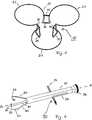
Das Hilfsmittel zum Einsetzen und Entfernen des chirurgischen Retraktors nach dieser Erfindung besitzt folgende wesentliche Elemente: eine Anzahl von Greifarmen, die der Anzahl der Retraktionselemente entspricht oder wenigstens zwei und vorzugsweise wenigstens drei beträgt, wobei die Greifarme mit ihren Greifenden gemeinsam eine Klaue bilden, weiterhin ein für den formschlüssigen Eingriff an einem Retraktionselement, einem Übergangsbereich zwischen Retraktionselement und Grundrahmen oder einem Grundrahmenbestandteil ausgebildetes Greifende an jedem Greifarm und außerdem Mittel zum Zusammenpressen der Greifenden der Greifarme in Richtung einer gemeinsamen Mittelachse. Die Greifarme sind vorzugsweise an ihrem distalen Ende miteinander verbunden oder über einen zusätzlichen Geräteteil verbunden und sind zu ihrem Greifende hin, d. h. an ihrem proximalen Ende divergierend und weiter vorzugsweise elastisch federnd ausgebildet, um die Retraktionselemente oder Grundrahmenteile auch im entspannten Zustand des Retraktors von außen greifen zu können. Das Komprimieren des Retraktors durch das Hilfsmittel erfolgt durch Druck von außen nach innen. Das Hilfsmittel ist ein Greifwerkzeug mit einer Anzahl von Greifarmen, die in bevorzugter Ausführungsform der Anzahl der Retraktionselemente entspricht. Die Greifarme könnten jedoch in alternativer Ausführungsform auch an den Übergangsbereichen zwischen Grundrahmen und Retraktionselementen oder auch außen an den Federelementen angreifen.The aid for inserting and removing the surgical retractor according to this invention has the following essential elements: a number of gripping arms corresponding to the number of retraction elements or at least two, and preferably at least three, wherein the gripping arms together with their gripper ends form a claw further gripper end formed on each gripper arm for the positive engagement with a retraction element, a transition region between the retraction element and the base frame or a base frame component, and also means for compressing the gripping ends of the gripper arms in the direction of a common central axis. The gripping arms are preferably connected to each other at their distal end or connected via an additional device part and are towards their gripping end, d. H. diverging at its proximal end and further preferably formed elastically resilient so as to be able to grip the retraction elements or basic frame parts from the outside in the relaxed state of the retractor. Compressing the retractor by the aid is done by pressure from outside to inside. The aid is a gripping tool with a number of gripping arms, which in a preferred embodiment corresponds to the number of retraction elements. However, in an alternative embodiment, the gripping arms could also act on the transition areas between the base frame and retraction elements or else on the outside of the spring elements.
Durch die divergierende Ausbildung der Greifarme zu ihrem Greifende hin können die Mittel zum Zusammenpressen der Greifenden insbesondere eine um die Greifarme angeordnete verschiebliche Hülse umfassen. Diese drängt die Greifarme in Richtung einer gemeinsamen Mittelachse, wenn sie nach vorne zu den Greifenden hin verschoben wird, und gibt die durch die Rückstellkraft des Materials der Greifarme nach außen drängenden Greifenden wieder frei, wenn die Hülse nach hinten geschoben wird. Während die Mittel zum Zusammenpressen der Greifenden in Richtung der gemeinsamen Mittelachse wirken, das heißt während vorzugsweise die die Greifarme umgebende Hülse nach vorne geschoben wird, wird ein mit dem Hilfsmittel gehaltener Retraktor komprimiert und dadurch mit einer radial nach außen wirkenden Vorspannung versehen.Due to the divergent design of the gripping arms towards their gripping end, the means for compressing the gripping ends can in particular comprise a displaceable sleeve arranged around the gripping arms. This urges the gripping arms toward a common center axis when it is displaced forward to the gripping ends, and releases the gripping ends pushing outwards by the restoring force of the material of the gripping arms when the sleeve is pushed backwards. While the means for compressing the gripping ends act in the direction of the common central axis, that is, while preferably the sleeve surrounding the gripping arms is pushed forward, a retractor held with the aid is compressed and thereby provided with a radially outwardly acting bias.
Zum sicheren Halten des Retraktors benötigt das Hilfsmittel Greifenden, die mit Haltemitteln für den Retraktor ausgerüstet sind.To hold the retractor safely, the tool requires gripping ends equipped with retaining means for the retractor.
In bevorzugter Ausführungsform besitzt daher das Hilfsmittel formschlüssig zu einem Retraktorbereich ausgebildete Greifenden, was in besonders bevorzugter Ausführungsform eine geschlitzte Hülse umfasst, die so ausgebildet ist, dass sie einen in den Schlitz der Hülse einführbaren Steg eines Retraktionselements oder einen Bereich eines Federelements oder Grundrahmenteils umfassen und gegen einen Druck, der radial nach außen gerichtet ist, halten kann. Alternativ kann anstelle der geschlitzten Hülse auch ein Haken beziehungsweise vorzugsweise ein Blade(Blatt)-förmiger breiter Haken am Greifende an den Greifarmen angeformt sein. Die Funktion ist in beiden Fällen gleich.In a preferred embodiment, therefore, the aid has a form-fitting trained to a retractor gripper ends, which comprises in a particularly preferred embodiment, a slotted sleeve which is formed so as to include a insertable into the slot of the sleeve web of a retraction or a portion of a spring element or base frame part and against a pressure that is directed radially outward can hold. Alternatively, instead of the slotted sleeve, a hook or, preferably, a blade (leaf) -shaped, wide hook can be integrally formed on the gripping arms at the gripping end. The function is the same in both cases.
Ein erfindungsgemäßes chirurgisches Verfahren zur Rekonstruktion oder zum Ersatz der Aortenklappe beginnt mit der Anästhesie des Patienten. Die Inzision erfolgt longitudinal über dem Sternum, das seinerseits longitudinal eröffnet wird. Ein Thorax-Spreizer wird so platziert, dass der Brustraum zugänglich wird. Das Gewebe um das Herz herum wird präpariert, so dass das Perikard eröffnet werden kann. Über Aorta und rechter Herzkammer wird ein kardiopulmonaler Bypass eingerichtet und der Patient an eine Herz-Lungen-Maschine angeschlossen. Die Aorta ascendens wird zwischen dem Abgang des Truncus brachiocephalicus und den Koronarostien abgeklemmt, das Herz über die Zufuhr von Kardioplegika arretiert und die Aorta transversal, distal der Aortenklappe eröffnet. Der erfindungsgemäße Retraktor wird komprimiert (die Kompression erfolgt entweder manuell oder mit Hilfe eines erfindungsgemäßen Hilfsmittels zum Einsetzen und Entfernen des chirurgischen Retraktors). Der komprimierte Retraktor wird in das Lumen der thorakalen Aorta eingeführt und so positioniert, dass der Bereich des Retraktors, an dem Grundrahmen und Retraktionselemente ineinander übergehen, am Rand des transversal eröffneten Gefässes zu liegen kommt. Nach der Positionierung kann der Grundrahmen zur Aorta ascendens in Richtung auf das Herz umgeklappt werden, so dass der ohnehin selbsthaltende Retraktor über die kleeblattartig angeordneten Federelemente zusätzliche Bereiche des Herzens mit retrahiert. Die luminal befindlichen Retraktionselemente ermöglichen über eine Retraktion der drei Aortensinus (linker, rechten und posteriorem Sinus valsalvae) eine optimale Sicht und einen optimalen Zugriff auf die Aortenklappe. Nach Reparatur oder Ersatz der Aortenklappe wird die in das Herz eingedrungene Luft entfernt und die Aorta durch Naht geschlossen. Die Klemmen, die zwischen Abgang des Truncus brachiocephalicus und den Koronarostien an der Aorta ascendens platziert waren, werden entfernt und der Patient von der Herz-Lungen-Maschine entwöhnt. Nach dem Entfernen der Bypass-Kanülen wird das Sternum verdrahtet und das durchtrennte Gewebe verschlossen.A surgical procedure for the reconstruction or replacement of the aortic valve according to the invention begins with the anesthesia of the patient. The incision is made longitudinally over the sternum, which in turn opens longitudinally. A thorax spreader is placed so that the chest becomes accessible. The tissue around the heart is prepared so that the pericardium can be opened. A cardiopulmonary bypass is established through the aorta and right ventricle, and the patient is connected to a heart-lung machine. The aorta ascendens is clamped between the exit of the brachiocephalic trunk and the coronary ostia, the heart arrested by the supply of cardioplegics and the aorta opened transversally, distal to the aortic valve. The retractor according to the invention is compressed (the compression takes place either manually or with the aid of an inventive means for inserting and removing the surgical retractor). The compressed retractor is inserted into the lumen of the thoracic aorta and positioned so that the area of the retractor, at which base frame and retraction elements merge into one another, comes to rest on the edge of the transversely opened vessel. After positioning, the base frame to the aorta ascendens can be folded in the direction of the heart, so that the already self-retaining retractor on the clover-like arranged spring elements additional areas of the heart are retracted. The luminal retraction elements allow optimal vision and access to the aortic valve through retraction of the three aortic sinus (left, right and posterior sinus valsalvae). After repair or replacement of the aortic valve, the air that has entered the heart is removed and the aorta is closed by suturing. The clamps placed between the exit of the brachiocephalic trunk and the coronary artery at the ascending aorta are removed and the patient is weaned from the heart-lung machine. After removing the bypass cannulas, the sternum is wired and the severed tissue is sealed.
Im Folgenden wird die Erfindung anhand von in den Figuren dargestellten Ausführungsbeispielen näher erläutert. Die Ausführungsbeispiele sollen der Veranschaulichung der Erfindung, nicht jedoch ihrer Beschränkung dienen.In the following, the invention will be explained in more detail with reference to exemplary embodiments illustrated in the figures. The embodiments are intended to illustrate the invention, but not its limitation.
Es zeigenShow it
Der in
Wenn der Retraktor
Größere Ausführungsformen unter anderem für Eingriffe an großlumigen röhrenförmigen Organen wie Magen-Darm, Speiseröhre, Luftröhre oder kleinere Ausführungsformen für Herzoperationen an Kindern sind ebenfalls möglich. Die genauen Größenordnungen bestimmt der Fachmann im Zusammenwirken mit dem Operateur.Larger embodiments, inter alia, for interventions on large-lumen tubular organs such as the gastrointestinal, esophagus, trachea or smaller embodiments for heart surgery on children are also possible. The exact magnitudes determined by the expert in cooperation with the surgeon.
Die
BezugszeichenlisteLIST OF REFERENCE NUMBERS
- 1010
- Retraktorretractor
- 2020
- Grundrahmenbase frame
- 2121
- Federelementspring element
- 3030
- RetraktionselementRetraktionselement
- 4040
- Aorta aszendensAorta ascendens
- 5050
- Klappenringvalve ring
- 7070
- Hilfsmittelaid
- 8080
- Greifarmclaw arm
- 8282
- Greifendecross
- 8686
- GreifhakenGrappling hook
- 9090
- Mittel zum Zusammenpressen der GreifarmeMeans for compressing the gripping arms
- 9292
- Hülseshell
- 9494
- Greifsteggripping stud
- 9696
- Endplatteendplate
- 9898
- Schlitzslot
ZITATE ENTHALTEN IN DER BESCHREIBUNG QUOTES INCLUDE IN THE DESCRIPTION
Diese Liste der vom Anmelder aufgeführten Dokumente wurde automatisiert erzeugt und ist ausschließlich zur besseren Information des Lesers aufgenommen. Die Liste ist nicht Bestandteil der deutschen Patent- bzw. Gebrauchsmusteranmeldung. Das DPMA übernimmt keinerlei Haftung für etwaige Fehler oder Auslassungen.This list of the documents listed by the applicant has been generated automatically and is included solely for the better information of the reader. The list is not part of the German patent or utility model application. The DPMA assumes no liability for any errors or omissions.
Zitierte PatentliteraturCited patent literature
- US 6074343[0008]US 6074343[0008]
- US 2005092333 A1[0010]US 2005092333 A1[0010]
Claims (12)
Translated fromGermanPriority Applications (2)
| Application Number | Priority Date | Filing Date | Title |
|---|---|---|---|
| DE102010025303ADE102010025303A1 (en) | 2010-06-28 | 2010-06-28 | Surgical retractor for expansion and retention of e.g. organ walls of patient, has retraction element connected over spring elements of base frame, where base frame is designed as radially outwardly acting cup expander spring |
| DE201120101601DE202011101601U1 (en) | 2010-06-28 | 2011-05-31 | Surgical retractor |
Applications Claiming Priority (1)
| Application Number | Priority Date | Filing Date | Title |
|---|---|---|---|
| DE102010025303ADE102010025303A1 (en) | 2010-06-28 | 2010-06-28 | Surgical retractor for expansion and retention of e.g. organ walls of patient, has retraction element connected over spring elements of base frame, where base frame is designed as radially outwardly acting cup expander spring |
Publications (1)
| Publication Number | Publication Date |
|---|---|
| DE102010025303A1true DE102010025303A1 (en) | 2011-12-29 |
Family
ID=44974291
Family Applications (2)
| Application Number | Title | Priority Date | Filing Date |
|---|---|---|---|
| DE102010025303AWithdrawnDE102010025303A1 (en) | 2010-06-28 | 2010-06-28 | Surgical retractor for expansion and retention of e.g. organ walls of patient, has retraction element connected over spring elements of base frame, where base frame is designed as radially outwardly acting cup expander spring |
| DE201120101601Expired - LifetimeDE202011101601U1 (en) | 2010-06-28 | 2011-05-31 | Surgical retractor |
Family Applications After (1)
| Application Number | Title | Priority Date | Filing Date |
|---|---|---|---|
| DE201120101601Expired - LifetimeDE202011101601U1 (en) | 2010-06-28 | 2011-05-31 | Surgical retractor |
Country Status (1)
| Country | Link |
|---|---|
| DE (2) | DE102010025303A1 (en) |
Cited By (1)
| Publication number | Priority date | Publication date | Assignee | Title |
|---|---|---|---|---|
| CN111803152A (en)* | 2020-07-14 | 2020-10-23 | 无锡市第九人民医院 | Surgical annular minimally invasive retractor |
Families Citing this family (3)
| Publication number | Priority date | Publication date | Assignee | Title |
|---|---|---|---|---|
| DE102012001500B4 (en) | 2012-01-27 | 2019-04-25 | Cardiomedical Gmbh | Surgical retractor |
| CN103654881B (en)* | 2013-10-23 | 2015-10-28 | 北京工业大学 | For the lobe leaf shaping apparatus of aortic valve free edge suspension operation |
| WO2019213582A1 (en)* | 2018-05-03 | 2019-11-07 | Price Bobby S | Cardiac atrial retractor ring |
Citations (5)
| Publication number | Priority date | Publication date | Assignee | Title |
|---|---|---|---|---|
| US2812758A (en)* | 1955-07-26 | 1957-11-12 | John C Blumenschein | Surgical retractor |
| US6074343A (en) | 1999-04-16 | 2000-06-13 | Nathanson; Michael | Surgical tissue retractor |
| DE69132488T2 (en)* | 1990-10-09 | 2001-04-05 | Medtronic, Inc. | DEVICE FOR MANIPULATING MATERIAL |
| US20050092333A1 (en) | 1996-02-19 | 2005-05-05 | Cosgrove Delos M. | Minimally invasive cardiac surgery procedure |
| US20060063979A1 (en)* | 2004-08-25 | 2006-03-23 | Kenneth Rosenblood | Retracting devices |
- 2010
- 2010-06-28DEDE102010025303Apatent/DE102010025303A1/ennot_activeWithdrawn
- 2011
- 2011-05-31DEDE201120101601patent/DE202011101601U1/ennot_activeExpired - Lifetime
Patent Citations (5)
| Publication number | Priority date | Publication date | Assignee | Title |
|---|---|---|---|---|
| US2812758A (en)* | 1955-07-26 | 1957-11-12 | John C Blumenschein | Surgical retractor |
| DE69132488T2 (en)* | 1990-10-09 | 2001-04-05 | Medtronic, Inc. | DEVICE FOR MANIPULATING MATERIAL |
| US20050092333A1 (en) | 1996-02-19 | 2005-05-05 | Cosgrove Delos M. | Minimally invasive cardiac surgery procedure |
| US6074343A (en) | 1999-04-16 | 2000-06-13 | Nathanson; Michael | Surgical tissue retractor |
| US20060063979A1 (en)* | 2004-08-25 | 2006-03-23 | Kenneth Rosenblood | Retracting devices |
Cited By (2)
| Publication number | Priority date | Publication date | Assignee | Title |
|---|---|---|---|---|
| CN111803152A (en)* | 2020-07-14 | 2020-10-23 | 无锡市第九人民医院 | Surgical annular minimally invasive retractor |
| CN111803152B (en)* | 2020-07-14 | 2022-09-23 | 无锡市第九人民医院 | Surgical annular minimally invasive retractor |
Also Published As
| Publication number | Publication date |
|---|---|
| DE202011101601U1 (en) | 2011-10-19 |
Similar Documents
| Publication | Publication Date | Title |
|---|---|---|
| DE69934318T2 (en) | AS A RETRACTOR INSERTABLE SURGICAL SEAM WITH FASTENER | |
| DE102013205519B4 (en) | Spreader for the atrium of the heart | |
| EP2262451B1 (en) | Stent, which can be decreased in diameter again in a controlled manner from the expanded state | |
| DE602004002605T2 (en) | Laminated surgical clip | |
| DE69629865T2 (en) | Intraluminal medical device, especially blood filter | |
| DE102006052564B3 (en) | Mitral valve stent for surgical implantation and fixation of heart valve prosthesis to heart, has stent clips arranged distally, where one of stent clips forms section that is externally rolled in unfolded condition of stent | |
| DE69520672T2 (en) | PROSTHETIC DEVICE MADE OF TEXTILE MATERIAL | |
| DE10049814B4 (en) | Device for supporting surgical procedures within a vessel, in particular for minimally invasive explantation and implantation of heart valves | |
| DE60128877T2 (en) | Clamp for attachment of Hernia mesh | |
| DE112019002229T5 (en) | Devices and methods for folding prosthetic implants | |
| CH636764A5 (en) | HOLDING DEVICE FOR THREADS, ESPECIALLY OPERATING THREADS. | |
| WO2018077821A1 (en) | Intraluminal vessel prosthesis for implantation into the heart or cardiac vessels of a patient | |
| WO2016193449A1 (en) | Stent | |
| DE10334868A1 (en) | Implantable device as a replacement organ valve | |
| DE102011054172A1 (en) | Transcatheter valve prosthesis | |
| DE102012107175B4 (en) | Medical closure device and system with such a closure device | |
| DE2340410C3 (en) | Surgical implant for protecting blood vessels | |
| DE202011051344U1 (en) | Spinal stabilization system and surgical device for temporarily stiffening a flexible intermediate portion of a spinal stabilization system connector | |
| DE202011101601U1 (en) | Surgical retractor | |
| EP3381376B1 (en) | Surgical retractor system with a retractor and an extractor | |
| DE102012001500B4 (en) | Surgical retractor | |
| DE29903943U1 (en) | Flat retention element for body parts | |
| DE102004027108B4 (en) | Implantable vascular support, which is expandable in at least two steps | |
| DE102018010278A9 (en) | FLAP REPAIR DEVICE | |
| EP1199989B1 (en) | Medical instrument and method for creating a cavity for an endoscopic intervention |
Legal Events
| Date | Code | Title | Description |
|---|---|---|---|
| R163 | Identified publications notified | ||
| R082 | Change of representative | Representative=s name:GRAMM, LINS & PARTNER PATENT- UND RECHTSANWAEL, DE | |
| R005 | Application deemed withdrawn due to failure to request examination |