DE102010023635A1 - Device and method for conveying liquids into the treatment unit of a medical treatment device, in particular into the dialyzer of a dialysis machine - Google Patents
Device and method for conveying liquids into the treatment unit of a medical treatment device, in particular into the dialyzer of a dialysis machineDownload PDFInfo
- Publication number
- DE102010023635A1 DE102010023635A1DE201010023635DE102010023635ADE102010023635A1DE 102010023635 A1DE102010023635 A1DE 102010023635A1DE 201010023635DE201010023635DE 201010023635DE 102010023635 ADE102010023635 ADE 102010023635ADE 102010023635 A1DE102010023635 A1DE 102010023635A1
- Authority
- DE
- Germany
- Prior art keywords
- liquid
- treatment unit
- balance chamber
- chamber
- line
- Prior art date
- Legal status (The legal status is an assumption and is not a legal conclusion. Google has not performed a legal analysis and makes no representation as to the accuracy of the status listed.)
- Ceased
Links
- 239000007788liquidSubstances0.000titleclaimsabstractdescription111
- 238000000502dialysisMethods0.000titleclaimsabstractdescription28
- 238000000034methodMethods0.000titleclaimsabstractdescription12
- 239000008280bloodSubstances0.000claimsabstractdescription34
- 210000004369bloodAnatomy0.000claimsabstractdescription34
- 239000012530fluidSubstances0.000claimsdescription37
- 238000007599dischargingMethods0.000claims2
- 238000011144upstream manufacturingMethods0.000claims1
- 239000000385dialysis solutionSubstances0.000description62
- 230000017531blood circulationEffects0.000description6
- 238000001631haemodialysisMethods0.000description6
- 230000000322hemodialysisEffects0.000description6
- XLYOFNOQVPJJNP-UHFFFAOYSA-NwaterSubstancesOXLYOFNOQVPJJNP-UHFFFAOYSA-N0.000description4
- 238000000108ultra-filtrationMethods0.000description3
- 208000009304Acute Kidney InjuryDiseases0.000description2
- 208000033626Renal failure acuteDiseases0.000description2
- 230000004087circulationEffects0.000description2
- 238000012423maintenanceMethods0.000description2
- 239000012528membraneSubstances0.000description2
- 238000005192partitionMethods0.000description2
- 239000000243solutionSubstances0.000description2
- BUHVIAUBTBOHAG-FOYDDCNASA-N(2r,3r,4s,5r)-2-[6-[[2-(3,5-dimethoxyphenyl)-2-(2-methylphenyl)ethyl]amino]purin-9-yl]-5-(hydroxymethyl)oxolane-3,4-diolChemical compoundCOC1=CC(OC)=CC(C(CNC=2C=3N=CN(C=3N=CN=2)[C@H]2[C@@H]([C@H](O)[C@@H](CO)O2)O)C=2C(=CC=CC=2)C)=C1BUHVIAUBTBOHAG-FOYDDCNASA-N0.000description1
- 230000000740bleeding effectEffects0.000description1
- 230000036770blood supplyEffects0.000description1
- 239000012141concentrateSubstances0.000description1
- 238000010276constructionMethods0.000description1
- 230000001419dependent effectEffects0.000description1
- 238000005429filling processMethods0.000description1
- 238000002615hemofiltrationMethods0.000description1
- 230000010354integrationEffects0.000description1
- 238000004519manufacturing processMethods0.000description1
- 238000009423ventilationMethods0.000description1
Images

Classifications
- A—HUMAN NECESSITIES
- A61—MEDICAL OR VETERINARY SCIENCE; HYGIENE
- A61M—DEVICES FOR INTRODUCING MEDIA INTO, OR ONTO, THE BODY; DEVICES FOR TRANSDUCING BODY MEDIA OR FOR TAKING MEDIA FROM THE BODY; DEVICES FOR PRODUCING OR ENDING SLEEP OR STUPOR
- A61M1/00—Suction or pumping devices for medical purposes; Devices for carrying-off, for treatment of, or for carrying-over, body-liquids; Drainage systems
- A61M1/14—Dialysis systems; Artificial kidneys; Blood oxygenators ; Reciprocating systems for treatment of body fluids, e.g. single needle systems for hemofiltration or pheresis
- A61M1/16—Dialysis systems; Artificial kidneys; Blood oxygenators ; Reciprocating systems for treatment of body fluids, e.g. single needle systems for hemofiltration or pheresis with membranes
- A61M1/1694—Dialysis systems; Artificial kidneys; Blood oxygenators ; Reciprocating systems for treatment of body fluids, e.g. single needle systems for hemofiltration or pheresis with membranes with recirculating dialysing liquid
- A—HUMAN NECESSITIES
- A61—MEDICAL OR VETERINARY SCIENCE; HYGIENE
- A61M—DEVICES FOR INTRODUCING MEDIA INTO, OR ONTO, THE BODY; DEVICES FOR TRANSDUCING BODY MEDIA OR FOR TAKING MEDIA FROM THE BODY; DEVICES FOR PRODUCING OR ENDING SLEEP OR STUPOR
- A61M1/00—Suction or pumping devices for medical purposes; Devices for carrying-off, for treatment of, or for carrying-over, body-liquids; Drainage systems
- A61M1/14—Dialysis systems; Artificial kidneys; Blood oxygenators ; Reciprocating systems for treatment of body fluids, e.g. single needle systems for hemofiltration or pheresis
- A61M1/16—Dialysis systems; Artificial kidneys; Blood oxygenators ; Reciprocating systems for treatment of body fluids, e.g. single needle systems for hemofiltration or pheresis with membranes
- A61M1/1621—Constructional aspects thereof
- A61M1/1635—Constructional aspects thereof with volume chamber balancing devices between used and fresh dialysis fluid
- A—HUMAN NECESSITIES
- A61—MEDICAL OR VETERINARY SCIENCE; HYGIENE
- A61M—DEVICES FOR INTRODUCING MEDIA INTO, OR ONTO, THE BODY; DEVICES FOR TRANSDUCING BODY MEDIA OR FOR TAKING MEDIA FROM THE BODY; DEVICES FOR PRODUCING OR ENDING SLEEP OR STUPOR
- A61M1/00—Suction or pumping devices for medical purposes; Devices for carrying-off, for treatment of, or for carrying-over, body-liquids; Drainage systems
- A61M1/14—Dialysis systems; Artificial kidneys; Blood oxygenators ; Reciprocating systems for treatment of body fluids, e.g. single needle systems for hemofiltration or pheresis
- A61M1/16—Dialysis systems; Artificial kidneys; Blood oxygenators ; Reciprocating systems for treatment of body fluids, e.g. single needle systems for hemofiltration or pheresis with membranes
- A61M1/1621—Constructional aspects thereof
- A61M1/165—Constructional aspects thereof with a dialyser bypass on the dialysis fluid line
- A—HUMAN NECESSITIES
- A61—MEDICAL OR VETERINARY SCIENCE; HYGIENE
- A61M—DEVICES FOR INTRODUCING MEDIA INTO, OR ONTO, THE BODY; DEVICES FOR TRANSDUCING BODY MEDIA OR FOR TAKING MEDIA FROM THE BODY; DEVICES FOR PRODUCING OR ENDING SLEEP OR STUPOR
- A61M1/00—Suction or pumping devices for medical purposes; Devices for carrying-off, for treatment of, or for carrying-over, body-liquids; Drainage systems
- A61M1/36—Other treatment of blood in a by-pass of the natural circulatory system, e.g. temperature adaptation, irradiation ; Extra-corporeal blood circuits
- A61M1/3621—Extra-corporeal blood circuits
- A61M1/3624—Level detectors; Level control
- Y—GENERAL TAGGING OF NEW TECHNOLOGICAL DEVELOPMENTS; GENERAL TAGGING OF CROSS-SECTIONAL TECHNOLOGIES SPANNING OVER SEVERAL SECTIONS OF THE IPC; TECHNICAL SUBJECTS COVERED BY FORMER USPC CROSS-REFERENCE ART COLLECTIONS [XRACs] AND DIGESTS
- Y10—TECHNICAL SUBJECTS COVERED BY FORMER USPC
- Y10T—TECHNICAL SUBJECTS COVERED BY FORMER US CLASSIFICATION
- Y10T137/00—Fluid handling
- Y10T137/0318—Processes
- Y10T137/0324—With control of flow by a condition or characteristic of a fluid
- Y—GENERAL TAGGING OF NEW TECHNOLOGICAL DEVELOPMENTS; GENERAL TAGGING OF CROSS-SECTIONAL TECHNOLOGIES SPANNING OVER SEVERAL SECTIONS OF THE IPC; TECHNICAL SUBJECTS COVERED BY FORMER USPC CROSS-REFERENCE ART COLLECTIONS [XRACs] AND DIGESTS
- Y10—TECHNICAL SUBJECTS COVERED BY FORMER USPC
- Y10T—TECHNICAL SUBJECTS COVERED BY FORMER US CLASSIFICATION
- Y10T137/00—Fluid handling
- Y10T137/2496—Self-proportioning or correlating systems
- Y10T137/2559—Self-controlled branched flow systems
- Y10T137/2574—Bypass or relief controlled by main line fluid condition
Landscapes
- Health & Medical Sciences (AREA)
- Heart & Thoracic Surgery (AREA)
- Urology & Nephrology (AREA)
- Vascular Medicine (AREA)
- Hematology (AREA)
- Engineering & Computer Science (AREA)
- Anesthesiology (AREA)
- Biomedical Technology (AREA)
- Life Sciences & Earth Sciences (AREA)
- Animal Behavior & Ethology (AREA)
- General Health & Medical Sciences (AREA)
- Public Health (AREA)
- Veterinary Medicine (AREA)
- Emergency Medicine (AREA)
- Cardiology (AREA)
- External Artificial Organs (AREA)
Abstract
Translated fromGermanDescription
Translated fromGermanDie Erfindung betrifft eine Vorrichtung und ein Verfahren zum Fördern von Flüssigkeiten in die Behandlungseinheit einer medizinischen Behandlungsvorrichtung, insbesondere in den Dialysator einer Dialysevorrichtung. Darüber hinaus betrifft die Erfindung eine extrakorporale Blutbehandlungsvorrichtung, insbesondere Dialysevorrichtung, die über eine Vorrichtung zum Fördern von Flüssigkeiten in die Behandlungseinheit, insbesondere den Dialysator, der Blutbehandlungsvorrichtung, insbesondere Dialysevorrichtung, verfügt.The invention relates to a device and a method for conveying liquids into the treatment unit of a medical treatment device, in particular into the dialyzer of a dialysis machine. Moreover, the invention relates to an extracorporeal blood treatment apparatus, in particular a dialysis apparatus, which has a device for conveying liquids into the treatment unit, in particular the dialyzer, the blood treatment apparatus, in particular a dialysis apparatus.
Es sind verschiedene Arten von Behandlungsvorrichtungen bekannt, die über eine mit einer Flüssigkeit zu versorgende Behandlungseinheit verfügen. Zu den bekannten Behandlungsvorrichtungen gehören beispielsweise die Blutbehandlungsvorrichtungen. Während der Blutbehandlung strömt das Blut des Patienten in einem extrakorporalen Blutkreislauf durch die Blutbehandlungseinheit. Bei den Vorrichtungen zur Hämodialyse, Hämofiltration und Hämodiafiltration ist die Blutbehandlungseinheit ein Dialysator oder Filter, der durch eine semipermeable Membran in eine Blutkammer und eine Dialysierflüssigkeitskammer getrennt ist. Während der Dialysebehandlung strömt das Blut in einem extrakorporalen Blutkreislauf durch die Blutkammer, während die Dialysierflüssigkeit in einem Dialysierflüssigkeitskreislauf durch die Dialysierflüssigkeitskammer des Dialysators strömt.Various types of treatment devices are known which have a treatment unit to be supplied with a liquid. The known treatment devices include, for example, the blood treatment devices. During the blood treatment, the patient's blood flows through the blood treatment unit in an extracorporeal blood circulation. In the devices for hemodialysis, hemofiltration and hemodiafiltration, the blood treatment unit is a dialyzer or filter which is separated by a semipermeable membrane into a blood chamber and a dialysis fluid chamber. During the dialysis treatment, the blood flows in an extracorporeal blood circulation through the blood chamber while the dialysis fluid flows in a dialysis fluid circuit through the dialysis fluid chamber of the dialyzer.
Wegen der großen Austauschmengen besteht bei den bekannten Verfahren und Vorrichtungen zur Blutbehandlung die Notwendigkeit einer exakten Bilanzierung der dem Patienten entzogenen Flüssigkeit und der dem Patienten zugeführten Flüssigkeit über die gesamte Behandlungszeit. Zum Stand der Technik gehören gravimetrische und volumetrische Bilanziervorrichtungen.Because of the large amount of replacements, the prior art blood treatment methods and devices require the need to accurately account for the fluid withdrawn from the patient and the fluid being delivered to the patient throughout the treatment period. The prior art includes gravimetric and volumetric balancers.
Eine Hämodiafiltrationsvorrichtung mit volumetrischer Bilanzierung ist beispielsweise aus der
Um einen kontinuierlichen Fluss von Dialysierflüssigkeit durch die Dialysierflüssigkeitskammer des Dialysators sicherstellen zu können, werden in der Praxis zwei Bilanzkammern parallel geschaltet, die den Dialysator wechselseitig mit frischer Dialysierflüssigkeit versorgen. Eine Bilanziereinheit mit zwei Bilanzkammern ist beispielsweise aus der
Während einer Dialysebehandlung beträgt der Dialysierflüssigkeitsfluss typischerweise 500 ml/min, kann aber in Abhängigkeit von der jeweiligen Behandlungssituation bis zu 1000 ml/min betragen. Bei einer Dialysedauer von 4 Stunden bedeutet dies einen Dialysierflüssigkeitsbedarf, der typischerweise zwischen 120 l beträgt, in Abhängigkeit von der jeweiligen Behandlungssituation aber auch über 200 l liegen kann.During a dialysis treatment, the dialysis fluid flow is typically 500 ml / min, but may be up to 1000 ml / min, depending on the particular treatment situation. With a dialysis duration of 4 hours, this means a dialysis fluid requirement, which is typically between 120 l, depending on the particular treatment situation but can also be over 200 l.
Aufgrund des großen Flüssigkeitsbedarfs bei der Dialyse hat sich die Herstellung des Dialysats aus Konzentraten und Reinwasser (RO-Wasser) in der Maschine etabliert, um die Vorhaltung größerer Mengen an Lösungen zu vermeiden. Das RO-Wasser wird zentral in der Klinik bereitgestellt und an die Dialaysemaschine in den Dialysestationen über Leitungen verteilt.Due to the large fluid requirement in dialysis, the production of dialysate from concentrates and pure water (RO water) has established in the machine to avoid the provision of larger amounts of solutions. The RO water is provided centrally in the clinic and distributed to the dialysis machine in the dialysis stations via lines.
Bei der Behandlung einer akuten Niereninsuffizienz, wie sie beispielsweise nach Unfällen vorkommen kann, die eine intensivmedizinische Betreuung des Patienten notwendig macht, ist im allgemeinen ein RO-Wasseranschluss nicht vorhanden. Die Dialysierflüssigkeit wird der Maschine dann über Behältnisse, beispielsweise Kanister oder Beutel, zur Verfügung gestellt.In the treatment of acute renal insufficiency, as may occur, for example, after accidents requiring intensive medical care of the patient, there is generally no RO water connection. The dialysis fluid is then provided to the machine via containers, for example canisters or bags.
Um den Handhabungsaufwand möglichst gering zu halten, wird insbesondere bei der intensivmedizinischen Betreuung einer akuten Niereninsuffizienz versucht, den Bedarf an Dialysierflüssigkeit zu verringern. Dies gelingt dadurch, dass die Dialysierflüssigkeit für eine gewisse Zeit über den Dialysator rezirkuliert wird. Damit kann der Dialysatbedarf auf Werte reduziert werden, die unter 100 ml/min liegen.In order to keep the handling effort as low as possible, an attempt is made to reduce the need for dialysis fluid, particularly in intensive care for acute renal insufficiency. This is achieved in that the dialysis fluid is recirculated over the dialyzer for a certain time. Thus, the dialysate requirement can be reduced to values that are below 100 ml / min.
Eine Blutbehandlungsvorrichtung mit einem Rezirkulationskreislauf ist beispielsweise aus der
Der Erfindung liegt die Aufgabe zugrunde, eine Vorrichtung zum Fördern von Flüssigkeiten in die Behandlungseinheit einer medizinischen Behandlungsvorrichtung, insbesondere in den Dialysator einer Dialysevorrichtung, zu schaffen, mit der sich der Bedarf an Dialysierflüssigkeit verringern lässt. Eine weitere Aufgabe der Erfindung ist, ein Verfahren zum Fördern von Flüssigkeiten in die Blutbehandlungseinheit einer medizinischen Behandlungsvorrichtung anzugeben, das eine Reduzierung des Bedarfs an Dialysierflüssigkeit erlaubt. Eine Aufgabe der Erfindung ist auch, eine extrakorporale Blutbehandlungsvorrichtung mit einer derartigen Vorrichtung zum Fördern von Flüssigkeiten zu schaffen.The invention has for its object to provide a device for conveying liquids in the treatment unit of a medical treatment device, in particular in the dialyzer of a dialysis machine, with which it is possible to reduce the need for dialysis. Another object of the invention is to provide a method for conveying liquids into the blood treatment unit of a medical treatment device, which reduces the need for Dialysis fluid allowed. An object of the invention is also to provide an extracorporeal blood treatment device with such a device for conveying liquids.
Die Lösung dieser Aufgaben erfolgt erfindungsgemäß mit den Merkmalen der unabhängigen Patentansprüche. Vorteilhafte Ausführungsformen der Erfindung sind Gegenstand der Unteransprüche.The solution of these objects is achieved according to the invention with the features of the independent claims. Advantageous embodiments of the invention are the subject of the dependent claims.
Die erfindungsgemäße Vorrichtung und das erfindungsgemäße Verfahren beruhen darauf, dass die Flüssigkeit, mit der die Behandlungseinheit versorgt wird, in einem die Behandlungseinheit einschließenden Flüssigkeitskreislauf zirkuliert. Zur Bilanzierung von frischer und verbrauchter Flüssigkeit, die der Behandlungseinheit zugeführt oder aus der Behandlungseinheit abgeführt wird, dient eine Bilanziereinheit, die grundsätzlich eine oder zwei Bilanzkammern aufweisen kann.The device according to the invention and the method according to the invention are based on the fact that the fluid with which the treatment unit is supplied circulates in a fluid circuit enclosing the treatment unit. For balancing fresh and spent liquid, which is supplied to the treatment unit or discharged from the treatment unit, serves a balancing unit, which may in principle have one or two balancing chambers.
Die erfindungsgemäße Vorrichtung und das erfindungsgemäße Verfahren zeichnen sich dadurch aus, dass die Bilanzkammer der Bilanziereinheit, oder die beiden Bilanzkammern der Bilanziereinheit in den die Behandlungseinheit einschließenden Flüssigkeitskreislauf eingebunden werden kann. Dadurch ist es möglich, dem Flüssigkeitskreislauf kontinuierlich frische Flüssigkeit zuzuführen bzw. verbrauchte Flüssigkeit aus dem Flüssigkeitskreislauf abzuführen. Dabei kann die Zu- und Abfuhr von frischer bzw. verbrauchter Flüssigkeit mit einer anderen Flussrate erfolgen, als mit der Flussrate, mit der die Flüssigkeit in dem Flüssigkeitskreislauf über die Behandlungseinheit zirkuliert. Folglich stellt sich in dem Flüssigkeitskreislauf eine „Flüssigkeit” ein, die in Abhängigkeit von dem Verhältnis der Flussraten in der Konzentration zwischen einer „frischen Flüssigkeit” und einer „verbrauchten Flüssigkeit” liegt. Dem die Blutbehandlungseinheit, insbesondere den Dialysator, einschließenden Flüssigkeitskreislauf kann unabhängig von der Zufuhr bzw. Abfuhr von frischer bzw. verbrauchter Flüssigkeit auch Flüssigkeit (Ultrafiltrat) entzogen werden.The device according to the invention and the method according to the invention are characterized in that the balancing chamber of the balancing unit, or the two balancing chambers of the balancing unit, can be integrated into the fluid circuit enclosing the treatment unit. This makes it possible to continuously supply fresh liquid to the liquid circuit or to remove used liquid from the liquid circuit. In this case, the supply and removal of fresh or spent fluid can be carried out at a different flow rate, as with the flow rate at which the liquid circulates in the fluid circuit via the treatment unit. Consequently, a "liquid" sets in the liquid circuit which, depending on the ratio of the flow rates, lies in the concentration between a "fresh liquid" and a "spent liquid". The blood circulation unit, in particular the dialyzer, enclosing liquid circuit can be withdrawn regardless of the supply or discharge of fresh or spent liquid and liquid (ultrafiltrate).
Bei einer bevorzugten Ausführungsform der Erfindung ist die Flussrate, mit der die Flüssigkeit über die Behandlungseinheit in dem Flüssigkeitskreislauf zirkuliert, größer als die Flussrate, mit der Flüssigkeit dem Flüssigkeitskreislauf zu- bzw. abgeführt wird.In a preferred embodiment of the invention, the flow rate at which the liquid circulates through the treatment unit in the fluid circuit is greater than the flow rate at which fluid is supplied to or removed from the fluid circuit.
Die erfindungsgemäße Vorrichtung verfügt über einen Bypass, der die von der Bilanzkammer zu der Behandlungseinheit führende Abflussleitung mit der von der Behandlungseinheit zu der Bilanzkammer führenden Zuflussleitung verbindet. Der Bypass erlaubt nicht nur eine kontinuierliche Zufuhr frischer Flüssigkeit in den die Behandlungseinheit einschließenden Flüssigkeitskreislauf, sondern auch die Aufrechterhaltung eines Flüssigkeitsflusses durch die Blutbehandlungseinheit, wenn die Bilanzkammer der Bilanziereinheit mit frischer Flüssigkeit unter Verwerfung verbrauchter Flüssigkeit befüllt wird. Wenn eine Bilanziereinheit mit zwei wechselseitig arbeitenden Bilanzkammern verwendet wird, kommt dieser Vorteil allerdings nicht zum Tragen. Eine besonders bevorzugte Ausführungsform der Erfindung sieht daher eine Bilanziereinheit mit nur einer Bilanzkammer vor. Bei dieser besonders bevorzugten Ausführungsform stellt der Bypass sicher, dass beim Umschalten der Bilanzkammer die Flüssigkeitsströmung durch die Blutbehandlungseinheit nicht abbricht. Dadurch ergibt sich ein vereinfachter Aufbau der Bilanziereinheit.The device according to the invention has a bypass, which connects the discharge line leading from the balancing chamber to the treatment unit with the inflow line leading from the treatment unit to the balancing chamber. The bypass allows not only a continuous supply of fresh liquid into the fluid circuit enclosing the treatment unit, but also the maintenance of a fluid flow through the blood treatment unit when the balance chamber of the balancing unit is filled with fresh fluid with rejection of spent fluid. If a balancing unit with two reciprocating balancing chambers is used, however, this advantage does not come into play. A particularly preferred embodiment of the invention therefore provides a balancing unit with only one balancing chamber. In this particularly preferred embodiment, the bypass ensures that the liquid flow through the blood treatment unit does not break off when the balance chamber is switched over. This results in a simplified construction of the balancing unit.
Die Mittel zum Fördern von Flüssigkeit in die bzw. aus der Bilanzkammer und die Mittel zum Unterbrechen des Zuflusses von Flüssigkeit in die Bilanzkammer bzw. des Abflusses von Flüssigkeit aus der Bilanzkammer können unterschiedlich ausgebildet sein. Zum Fördern von Flüssigkeit dienen vorzugsweise die bekannten okkludierenden Pumpen, in die sich Schlauchleitungen einlegen lassen. Zum Unterbrechen des Zuflusses bzw. Abflusses von Flüssigkeit dienen vorzugsweise die bekannten elektromagnetisch oder pneumatisch betätigbaren Absperrorgane, die in den Leitungen angeordnet sind. Eine Steuereinheit steuert die Mittel zum Fördern von Flüssigkeit und die Mittel zum Unterbrechen des Zuflusses bzw. Abflusses von Flüssigkeit an. Da okkludierende Pumpen im Stillstand die Schlauchleitung abklemmen, können die okkludierenden Pumpen auch Absperrorgane ersetzen.The means for conveying liquid into and out of the balance chamber and the means for interrupting the inflow of liquid into the balance chamber or the outflow of liquid from the balance chamber may be formed differently. To convey liquid, it is preferable to use the known occluding pumps in which hose lines can be inserted. To interrupt the inflow or outflow of liquid preferably serve the known electromagnetically or pneumatically actuated shut-off devices which are arranged in the lines. A control unit controls the means for conveying liquid and the means for interrupting the inflow or outflow of liquid. Since occluding pumps at standstill disconnect the tubing, the occluding pumps can also replace shut-off valves.
Bei einer besonders bevorzugten Ausführungsform weisen die Mittel zum Fördern von Flüssigkeit eine erste Pumpe auf, die in der von der Flüssigkeitsquelle zu der Bilanzkammer führenden Zuflussleitung angeordnet ist. Darüber hinaus weisen die Fördermittel zwei weitere Pumpen auf, die in der von der Bilanzkammer zu der Blutbehandlungseinheit führenden Abflussleitung angeordnet sind. Von diesen beiden Pumpen ist die eine Pumpe in dem Abschnitt dieser Abflussleitung angeordnet, der zu dem Punkt führt, an dem der eine Anschluss des Bypasses an die Abflussleitung angeschlossen ist, während die andere Pumpe in dem Abschnitt dieser Abflussleitung angeordnet ist, der von dem Anschlusspunkt des Bypasses abgeht. Die Flussraten dieser beiden Pumpen in der Abflussleitung geben die Flussrate vor, mit der frische Flüssigkeit dem Flüssigkeitskreislauf zugeführt bzw. verbrauchte Flüssigkeit aus dem Flüssigkeitskreislauf abgeführt wird.In a particularly preferred embodiment, the means for conveying fluid to a first pump, which is arranged in the leading from the liquid source to the balancing chamber inlet line. In addition, the conveying means comprise two further pumps, which are arranged in the discharge line leading from the balancing chamber to the blood treatment unit. Of these two pumps, one pump is disposed in the portion of this drainage conduit leading to the point where one port of the bypass is connected to the drainage conduit while the other pump is located in the portion of that drainage conduit which is from the attachment point going off the bypass. The flow rates of these two pumps in the drain line provide the flow rate at which fresh liquid is fed to the liquid loop, or spent liquid is removed from the liquid loop.
Bei der besonders bevorzugten Ausführungsform umfassen die Mittel zum Unterbrechen des Zuflusses und/oder Abflusses von Flüssigkeit ein erstes Absperrorgan, das in der von der Flüssigkeitsquelle zu der Bilanzkammer führenden ersten Zuflussleitung angeordnet ist, ein zweites Absperrorgan, das in der von der Bilanzkammer abgehenden und zu dem Abfluss führenden zweiten Abflussleitung angeordnet ist, ein drittes Absperrorgan, das in der von der Bilanzkammer abgehenden und zu der Blutbehandlungseinheit führenden zweiten Abflussleitung angeordnet ist, und ein viertes Absperrorgan, das in der von der Behandlungseinheit zu der Bilanzkammer führenden zweiten Zuflussleitung angeordnet ist. Sämtliche Absperrorgane werden von der Steuereinheit angesteuert.In the particularly preferred embodiment, the means for interrupting the inflow and / or outflow of liquid comprise a first obturator, which in the of the A second obturator disposed in the outgoing from the balance chamber and leading to the outflow second drain line, a third obturator disposed in the outgoing from the balance chamber and leading to the blood treatment unit second drain line is, and a fourth obturator, which is arranged in the second inflow line leading from the treatment unit to the balancing chamber. All shut-off devices are controlled by the control unit.
Die Steuereinheit ist bei der besonders bevorzugten Ausführungsform derart ausgebildet, dass in einem ersten Arbeitstakt eines ersten Arbeitszyklus von aufeinander folgenden Arbeitszyklen das erste und zweite Absperrorgan geöffnet und das dritte und vierte Absperrorgan geschlossen sind, wobei die erste und dritte Pumpe in Betrieb sind. In dem ersten Arbeitstakt wird die Bilanzkammer mit frischer Flüssigkeit unter Verwerfung verbrauchter Flüssigkeit befüllt. Während des Füllvorgangs der Bilanzkammer ist die Flüssigkeitsströmung durch die Behandlungseinheit nicht unterbrochen. An den ersten Arbeitstakt schließt sich ein zweiter Arbeitstakt an, in dem das erste und zweite Absperrorgan geschlossen und das dritte und vierte Absperrorgan geöffnet sind, wobei die zweite und dritte Pumpe in Betrieb sind. In dem zweiten Arbeitstakt zirkuliert die Flüssigkeit in dem die Behandlungseinheit einschließenden Flüssigkeitskreislauf. Dabei kann, muss aber nicht, frische Flüssigkeit dem Flüssigkeitskreislauf zugeführt bzw. aus dem Flüssigkeitskreislauf abgeführt werden.The control unit is formed in the particularly preferred embodiment such that in a first cycle of a first cycle of successive working cycles, the first and second shut-off and the third and fourth shut-off are closed, the first and third pump are in operation. In the first cycle, the balance chamber is filled with fresh liquid, with rejection of spent liquid. During the filling process of the balance chamber, the liquid flow through the treatment unit is not interrupted. The first power stroke is followed by a second power stroke in which the first and second shut-off elements are closed and the third and fourth shut-off devices are opened, with the second and third pumps in operation. In the second working cycle, the liquid circulates in the fluid circuit enclosing the treatment unit. It may, but does not necessarily, fresh liquid supplied to the liquid circuit or be discharged from the liquid circuit.
Eine weitere bevorzugte Ausführungsform sieht die Integration eines weiteren Absperrorgans im Bypass vor. Dieses Absperrorgan dient der besseren Befüllung und Entlüftung des Systems vor der Durchführung der Behandlung. Andererseits kann mit dem Absperrorgan im Bypass auch die Zirkulation in dem Flüssigkeitskreislauf unterbrochen werden.Another preferred embodiment provides for the integration of a further obturator in the bypass. This obturator is used to better fill and vent the system before performing the treatment. On the other hand, with the obturator in the bypass and the circulation in the fluid circuit can be interrupted.
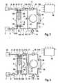
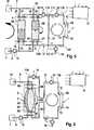
Im Folgenden werden Ausführungsbeispiele der Erfindung unter Bezugnahme auf die Zeichnungen näher erläutert.In the following, embodiments of the invention will be explained in more detail with reference to the drawings.
Es zeigen:Show it:
Die Erfindung wird nachfolgend am Beispiel einer Blutbehandlungsvorrichtung beschrieben, die über einen Dialysator als Blutbehandlungseinheit verfügt.
Die Dialysevorrichtung weist einen Dialysator
Der Dialysator
Zum Bilanzieren von frischer gegen verbrauchte Dialysierflüssigkeit dient eine Bilanziereinheit
Die Dialysierflüssigkeit wird in einer Dialysierflüssigkeitsquelle
Von dem zweiten Auslass
Bei den Zu- und Abflussleitungen
Die zweite Abflussleitung
In den ersten Abschnitt
In die erste Zuflussleitung
Die zentrale Steuereinheit
Der erste Arbeitstakt umfasst das Befüllen der Bilanzierkammer
Die erste Pumpe
An den ersten Arbeitstakt (
Während Dialysierflüssigkeit in dem Flüssigkeitskreislauf II durch den Dialysator
In Abhängigkeit von den Förderraten der zweiten und dritten Pumpe
An den zweiten Arbeitstakt (
Zum Befüllen und Entlüften des Flüssigkeitssystems wird das Absperrorgan
Die erfindungsgemäße Vorrichtung zum Versorgen des Dialysators mit Dialysierflüssigkeit hat den Vorteil, dass auf eine Bilanziereinheit mit zwei Bilanzkammern verzichtet werden kann. Auch mit einer Bilanziereinheit, die nur über eine Bilanzkammer verfügt, kann eine kontinuierliche Strömung von Dialysierflüssigkeit durch den Dialysator während der Bilanzierung von frischer gegen verbrauchte Dialysierflüssigkeit aufrecht erhalten werden.The device according to the invention for supplying the dialyzer with dialysis fluid has the advantage that it is possible to dispense with a balancing unit with two balancing chambers. Even with a balancing unit which has only one balance chamber, a continuous flow of dialysis fluid through the dialyzer can be maintained during the balancing of fresh versus used dialysis fluid.
ZITATE ENTHALTEN IN DER BESCHREIBUNG QUOTES INCLUDE IN THE DESCRIPTION
Diese Liste der vom Anmelder aufgeführten Dokumente wurde automatisiert erzeugt und ist ausschließlich zur besseren Information des Lesers aufgenommen. Die Liste ist nicht Bestandteil der deutschen Patent- bzw. Gebrauchsmusteranmeldung. Das DPMA übernimmt keinerlei Haftung für etwaige Fehler oder Auslassungen.This list of the documents listed by the applicant has been generated automatically and is included solely for the better information of the reader. The list is not part of the German patent or utility model application. The DPMA assumes no liability for any errors or omissions.
Zitierte PatentliteraturCited patent literature
- DE 2634238 A1[0004]DE 2634238 A1[0004]
- DE 2838414[0005, 0051]DE 2838414[0005, 0051]
- US 5685988[0010]US 5685988[0010]
Claims (16)
Translated fromGermanPriority Applications (7)
| Application Number | Priority Date | Filing Date | Title |
|---|---|---|---|
| DE201010023635DE102010023635A1 (en) | 2010-06-14 | 2010-06-14 | Device and method for conveying liquids into the treatment unit of a medical treatment device, in particular into the dialyzer of a dialysis machine |
| EP11732366.7AEP2579912B1 (en) | 2010-06-14 | 2011-06-14 | Method and device for delivering liquids into the treatment unit of a medical treatment device, in particular into the dialyser of a dialysis device |
| JP2013514581AJP5778265B2 (en) | 2010-06-14 | 2011-06-14 | Apparatus and method for transporting fluid into a treatment unit of a medical treatment device, particularly into a dialysis machine of a dialysis device |
| PCT/EP2011/002915WO2011157396A1 (en) | 2010-06-14 | 2011-06-14 | Method and device for delivering liquids into the treatment unit of a medical treatment device, in particular into the dialyser of a dialysis device |
| CN201180029575.0ACN102985121B (en) | 2010-06-14 | 2011-06-14 | Fluid is sent to the method and apparatus in the dialyser of the processing unit of Medical Treatment equipment, particularly dialysis machine |
| US13/703,691US9603987B2 (en) | 2010-06-14 | 2011-06-14 | Method and device for conveying fluids into the treatment unit of a medical treatment apparatus, in particular into the dialyzer of a dialysis apparatus |
| BR112012032035-1ABR112012032035B1 (en) | 2010-06-14 | 2011-06-14 | METHOD AND DEVICE FOR THE TRANSPORT OF FLUIDS TO THE TREATMENT UNIT OF A MEDICAL TREATMENT DEVICE, IN PARTICULAR FOR THE DIALYZER OF A DIALYSIS DEVICE |
Applications Claiming Priority (1)
| Application Number | Priority Date | Filing Date | Title |
|---|---|---|---|
| DE201010023635DE102010023635A1 (en) | 2010-06-14 | 2010-06-14 | Device and method for conveying liquids into the treatment unit of a medical treatment device, in particular into the dialyzer of a dialysis machine |
Publications (1)
| Publication Number | Publication Date |
|---|---|
| DE102010023635A1true DE102010023635A1 (en) | 2011-12-15 |
Family
ID=44628496
Family Applications (1)
| Application Number | Title | Priority Date | Filing Date |
|---|---|---|---|
| DE201010023635CeasedDE102010023635A1 (en) | 2010-06-14 | 2010-06-14 | Device and method for conveying liquids into the treatment unit of a medical treatment device, in particular into the dialyzer of a dialysis machine |
Country Status (7)
| Country | Link |
|---|---|
| US (1) | US9603987B2 (en) |
| EP (1) | EP2579912B1 (en) |
| JP (1) | JP5778265B2 (en) |
| CN (1) | CN102985121B (en) |
| BR (1) | BR112012032035B1 (en) |
| DE (1) | DE102010023635A1 (en) |
| WO (1) | WO2011157396A1 (en) |
Cited By (3)
| Publication number | Priority date | Publication date | Assignee | Title |
|---|---|---|---|---|
| WO2015135989A1 (en)* | 2014-03-13 | 2015-09-17 | Fresenius Medical Care Deutschland Gmbh | Device and method for balancing between an inflow into and an outflow from a medical treatment device |
| US20160310655A1 (en)* | 2013-12-13 | 2016-10-27 | Fresenius Medical Care Deutschland Gmbh | Apparatus for Extracorporeal Blood Treatment and Method for Operating An Extracorporeal Blood Treatment Apparatus |
| DE102023132536A1 (en)* | 2023-11-22 | 2025-05-22 | B.Braun Avitum Ag | Extracorporeal blood treatment machine with recirculation circuit in bypass and control procedure |
Families Citing this family (26)
| Publication number | Priority date | Publication date | Assignee | Title |
|---|---|---|---|---|
| US10089443B2 (en) | 2012-05-15 | 2018-10-02 | Baxter International Inc. | Home medical device systems and methods for therapy prescription and tracking, servicing and inventory |
| CN103889481B (en) | 2011-08-02 | 2016-03-09 | 美敦力公司 | Hemodialysis system with flow path with controlled compliance volume |
| EP2662101B2 (en)* | 2012-05-09 | 2018-05-30 | D_MED Consulting AG | Method for priming a haemodialysis device |
| US11154648B2 (en) | 2013-01-09 | 2021-10-26 | Medtronic, Inc. | Fluid circuits for sorbent cartridge with sensors |
| US9713666B2 (en) | 2013-01-09 | 2017-07-25 | Medtronic, Inc. | Recirculating dialysate fluid circuit for blood measurement |
| US10850016B2 (en) | 2013-02-01 | 2020-12-01 | Medtronic, Inc. | Modular fluid therapy system having jumpered flow paths and systems and methods for cleaning and disinfection |
| US10010663B2 (en) | 2013-02-01 | 2018-07-03 | Medtronic, Inc. | Fluid circuit for delivery of renal replacement therapies |
| US9623164B2 (en) | 2013-02-01 | 2017-04-18 | Medtronic, Inc. | Systems and methods for multifunctional volumetric fluid control |
| DE102013019356A1 (en) | 2013-11-19 | 2015-06-03 | Fresenius Medical Care Deutschland Gmbh | Apparatus and method for balancing fluids for an extracorporeal blood treatment device |
| US9884145B2 (en) | 2013-11-26 | 2018-02-06 | Medtronic, Inc. | Parallel modules for in-line recharging of sorbents using alternate duty cycles |
| US10537875B2 (en) | 2013-11-26 | 2020-01-21 | Medtronic, Inc. | Precision recharging of sorbent materials using patient and session data |
| WO2015199768A1 (en) | 2014-06-24 | 2015-12-30 | Medtronic, Inc. | Stacked sorbent assembly |
| ES2989503T3 (en) | 2014-06-24 | 2024-11-26 | Mozarc Medical Us Llc | Modular dialysate regeneration assembly |
| WO2017084682A1 (en) | 2015-11-20 | 2017-05-26 | Hepa Wash Gmbh | Method for extracorporeal carbon dioxide removal |
| WO2017084683A1 (en) | 2015-11-20 | 2017-05-26 | Hepa Wash Gmbh | Method for extracorporeal lung support |
| CN105727382B (en)* | 2016-01-28 | 2017-12-22 | 龚德华 | A kind of continous way CRRT machine capability bascules of two tripper |
| EP3429657B1 (en)* | 2016-03-14 | 2022-05-18 | ADVITOS GmbH | Systems or apparatuses for performing dialysis |
| DE102016010222A1 (en)* | 2016-08-20 | 2018-02-22 | Fresenius Medical Care Deutschland Gmbh | Device and method for providing dialysis fluid and dialysis device |
| US10981148B2 (en) | 2016-11-29 | 2021-04-20 | Medtronic, Inc. | Zirconium oxide module conditioning |
| EP3634530B1 (en) | 2017-05-22 | 2025-07-02 | ADVITOS GmbH | Methods and systems for removing carbon dioxide |
| US10960381B2 (en) | 2017-06-15 | 2021-03-30 | Medtronic, Inc. | Zirconium phosphate disinfection recharging and conditioning |
| DE102017131192A1 (en)* | 2017-12-22 | 2019-06-27 | Fresenius Medical Care Deutschland Gmbh | Buffer solution for reducing the carbon dioxide content in extracorporeal blood |
| US12285552B2 (en) | 2018-08-14 | 2025-04-29 | Mozarc Medical Us Llc | Precision dialysis therapy based on sorbent effluent analysis |
| US11213616B2 (en) | 2018-08-24 | 2022-01-04 | Medtronic, Inc. | Recharge solution for zirconium phosphate |
| DE102019130294A1 (en)* | 2019-11-11 | 2021-05-12 | Fresenius Medical Care Deutschland Gmbh | Dialysis machine for carrying out a push-pull dialysis treatment |
| US12397093B2 (en) | 2021-05-18 | 2025-08-26 | Mozarc Medical Us Llc | Sorbent cartridge designs |
Citations (5)
| Publication number | Priority date | Publication date | Assignee | Title |
|---|---|---|---|---|
| DE2634238A1 (en) | 1976-07-30 | 1978-02-02 | Berghof Forschungsinst | Dialysis liquor substitution in blood dialysis - uses cells with flexible membranes to allow balanced replacement |
| DE2838414A1 (en) | 1978-09-02 | 1980-03-06 | Fresenius Chem Pharm Ind | DEVICE FOR ULTRAFILTRATION CONTROL IN HAEMODIALYSIS |
| US5685988A (en) | 1993-09-15 | 1997-11-11 | Malchesky; Paul | Dialysis process and system |
| DE29902953U1 (en)* | 1999-02-19 | 2000-07-13 | Fresenius Medical Care Deutschland GmbH, 61352 Bad Homburg | Device for dialysis treatment |
| EP2005982A1 (en)* | 2007-06-20 | 2008-12-24 | B. Braun Avitum AG | Method for determining the reduction ratio or the Kt/V value of a kidney substitution treatment and apparatus for the realisation of the method |
Family Cites Families (9)
| Publication number | Priority date | Publication date | Assignee | Title |
|---|---|---|---|---|
| US4209391A (en) | 1978-11-06 | 1980-06-24 | Cordis Dow Corp. | Apparatus and method for automatically controlling hemodialysis at a pre-selected ultrafiltration rate |
| FR2680975B1 (en)* | 1991-09-10 | 1998-12-31 | Hospal Ind | ARTIFICIAL KIDNEY WITH MEANS FOR DETERMINING A SUBSTANCE IN BLOOD. |
| DE4239937C2 (en) | 1992-11-27 | 1995-08-24 | Fresenius Ag | Method for determining the functionality of a partial device of a hemodialysis machine and device for carrying out this method |
| IT1260992B (en) | 1993-10-15 | 1996-04-29 | Hospal Dasco Spa | MACHINE FOR EXTRA-BODY DIALYSIS. |
| JP3892921B2 (en)* | 1996-11-19 | 2007-03-14 | 東レ・メディカル株式会社 | Hemodialysis machine |
| DE19702211A1 (en) | 1997-01-23 | 1998-07-30 | Polaschegg Hans Dietrich Dr | Haemodialysis appts |
| DE19708391C1 (en)* | 1997-03-01 | 1998-10-22 | Fresenius Medical Care De Gmbh | Method and device for ultrafiltration in hemodialysis |
| JP4093695B2 (en)* | 1999-02-19 | 2008-06-04 | フレセニウス・メディカル・ケア・ドイッチュラント・ゲゼルシャフト・ミット・ベシュレンクテル・ハフツング | Dialysis treatment device |
| US9101716B2 (en)* | 2008-02-01 | 2015-08-11 | Baxter International Inc. | Multi-pass dialysis |
- 2010
- 2010-06-14DEDE201010023635patent/DE102010023635A1/ennot_activeCeased
- 2011
- 2011-06-14WOPCT/EP2011/002915patent/WO2011157396A1/enactiveApplication Filing
- 2011-06-14CNCN201180029575.0Apatent/CN102985121B/enactiveActive
- 2011-06-14USUS13/703,691patent/US9603987B2/enactiveActive
- 2011-06-14JPJP2013514581Apatent/JP5778265B2/enactiveActive
- 2011-06-14BRBR112012032035-1Apatent/BR112012032035B1/enactiveIP Right Grant
- 2011-06-14EPEP11732366.7Apatent/EP2579912B1/enactiveActive
Patent Citations (5)
| Publication number | Priority date | Publication date | Assignee | Title |
|---|---|---|---|---|
| DE2634238A1 (en) | 1976-07-30 | 1978-02-02 | Berghof Forschungsinst | Dialysis liquor substitution in blood dialysis - uses cells with flexible membranes to allow balanced replacement |
| DE2838414A1 (en) | 1978-09-02 | 1980-03-06 | Fresenius Chem Pharm Ind | DEVICE FOR ULTRAFILTRATION CONTROL IN HAEMODIALYSIS |
| US5685988A (en) | 1993-09-15 | 1997-11-11 | Malchesky; Paul | Dialysis process and system |
| DE29902953U1 (en)* | 1999-02-19 | 2000-07-13 | Fresenius Medical Care Deutschland GmbH, 61352 Bad Homburg | Device for dialysis treatment |
| EP2005982A1 (en)* | 2007-06-20 | 2008-12-24 | B. Braun Avitum AG | Method for determining the reduction ratio or the Kt/V value of a kidney substitution treatment and apparatus for the realisation of the method |
Cited By (5)
| Publication number | Priority date | Publication date | Assignee | Title |
|---|---|---|---|---|
| US20160310655A1 (en)* | 2013-12-13 | 2016-10-27 | Fresenius Medical Care Deutschland Gmbh | Apparatus for Extracorporeal Blood Treatment and Method for Operating An Extracorporeal Blood Treatment Apparatus |
| US11246969B2 (en)* | 2013-12-13 | 2022-02-15 | Fresenius Medical Care Deutschland Gmbh | Apparatus for extracorporeal blood treatment and method for operating an extracorporeal blood treatment apparatus |
| WO2015135989A1 (en)* | 2014-03-13 | 2015-09-17 | Fresenius Medical Care Deutschland Gmbh | Device and method for balancing between an inflow into and an outflow from a medical treatment device |
| US10220130B2 (en) | 2014-03-13 | 2019-03-05 | Fresenius Medical Care Deutschland Gmbh | Device and method for balancing between an inflow into and an outflow out of a medical treatment device |
| DE102023132536A1 (en)* | 2023-11-22 | 2025-05-22 | B.Braun Avitum Ag | Extracorporeal blood treatment machine with recirculation circuit in bypass and control procedure |
Also Published As
| Publication number | Publication date |
|---|---|
| BR112012032035A2 (en) | 2016-11-08 |
| JP5778265B2 (en) | 2015-09-16 |
| EP2579912A1 (en) | 2013-04-17 |
| BR112012032035B1 (en) | 2020-10-06 |
| WO2011157396A1 (en) | 2011-12-22 |
| US20130087210A1 (en) | 2013-04-11 |
| JP2013532018A (en) | 2013-08-15 |
| US9603987B2 (en) | 2017-03-28 |
| EP2579912B1 (en) | 2017-01-04 |
| CN102985121A (en) | 2013-03-20 |
| CN102985121B (en) | 2016-08-17 |
Similar Documents
| Publication | Publication Date | Title |
|---|---|---|
| EP2579912B1 (en) | Method and device for delivering liquids into the treatment unit of a medical treatment device, in particular into the dialyser of a dialysis device | |
| DE102006042120B3 (en) | Blood treatment device and method for draining a blood tubing set of a blood treatment device | |
| EP1996253B1 (en) | Method for at least partially draining an extracorporeal blood flow and haemodialysis device for use with said method | |
| EP1585564A2 (en) | Method and device for supply of a dialysis unit with dialysis fluid | |
| DE60127657T2 (en) | Blood purification system | |
| DE102011008223A1 (en) | Dialysis supply system | |
| DE102008050367A1 (en) | Device and method for extracorporeal blood treatment in single-needle operation | |
| DE102006061184A1 (en) | Method of priming a blood tubing set | |
| DE102014015858A1 (en) | Method and device for supplying a dialysis machine with dialysis fluid | |
| EP1858566B1 (en) | Device for the removal of substances form liquids in particular blood | |
| DE3786138T2 (en) | Treatment cycle for the regeneration of body fluid. | |
| DE19962314B4 (en) | Device for peritoneal dialysis | |
| EP2588158A1 (en) | Medical functional device, process fluid, and medical treatment appliance | |
| WO2015135989A1 (en) | Device and method for balancing between an inflow into and an outflow from a medical treatment device | |
| DE3147377A1 (en) | METHOD AND DEVICE FOR THE EXTRACORPORAL REMOVAL OF TOXINS TIED TO PROTEIN BODIES | |
| EP3079736B1 (en) | Apparatus for extracorporeal blood treatment | |
| DE102016010222A1 (en) | Device and method for providing dialysis fluid and dialysis device | |
| EP0366950B1 (en) | Hemodialysis apparatus with a deaeration device | |
| DE102011016870B4 (en) | Device for conveying a fluid to a filter unit of a medical treatment device and method for measuring the pressure in the fluid flow system of such a device | |
| EP0513672B1 (en) | Blood treatment device with volume balanced flow | |
| DE102019118548A1 (en) | Dialysis machine and method for operating a balance chamber system of a dialysis machine | |
| DE102019130294A1 (en) | Dialysis machine for carrying out a push-pull dialysis treatment | |
| DE102011016869A1 (en) | Apparatus and method for conveying a liquid to a filter unit of a medical treatment device | |
| DE102015002073A1 (en) | Apparatus for carrying out apheresis treatment | |
| DE3046162A1 (en) | Blood dialysis unit with membrane filter - uses double pendulum piston pump to ensure separation of fresh and used dialysate |
Legal Events
| Date | Code | Title | Description |
|---|---|---|---|
| R082 | Change of representative | Representative=s name:OPPERMANN, FRANK, DIPL.-ING., DE | |
| R016 | Response to examination communication | ||
| R016 | Response to examination communication | ||
| R002 | Refusal decision in examination/registration proceedings | ||
| R003 | Refusal decision now final |