DE102010022959A1 - Pneumatic suspension systems for vehicles and methods for pneumatic suspension of vehicle parts - Google Patents
Pneumatic suspension systems for vehicles and methods for pneumatic suspension of vehicle partsDownload PDFInfo
- Publication number
- DE102010022959A1 DE102010022959A1DE102010022959ADE102010022959ADE102010022959A1DE 102010022959 A1DE102010022959 A1DE 102010022959A1DE 102010022959 ADE102010022959 ADE 102010022959ADE 102010022959 ADE102010022959 ADE 102010022959ADE 102010022959 A1DE102010022959 A1DE 102010022959A1
- Authority
- DE
- Germany
- Prior art keywords
- air
- air spring
- suspension system
- control device
- spring
- Prior art date
- Legal status (The legal status is an assumption and is not a legal conclusion. Google has not performed a legal analysis and makes no representation as to the accuracy of the status listed.)
- Withdrawn
Links
- 239000000725suspensionSubstances0.000titleclaimsabstractdescription57
- 238000000034methodMethods0.000titleclaimsdescription10
- 230000033001locomotionEffects0.000claimsdescription34
- 230000010355oscillationEffects0.000claimsdescription10
- 230000003111delayed effectEffects0.000claims1
- 238000007599dischargingMethods0.000abstractdescription4
- 230000001105regulatory effectEffects0.000abstract1
- 230000000977initiatory effectEffects0.000description9
- 230000003534oscillatory effectEffects0.000description6
- 235000012907honeyNutrition0.000description3
- 238000007789sealingMethods0.000description3
- 238000013016dampingMethods0.000description2
- 230000001419dependent effectEffects0.000description2
- 238000010586diagramMethods0.000description2
- 210000003746featherAnatomy0.000description2
- 230000006835compressionEffects0.000description1
- 238000007906compressionMethods0.000description1
- 238000006073displacement reactionMethods0.000description1
- 238000009434installationMethods0.000description1
- 230000000979retarding effectEffects0.000description1
Images


Classifications
- B—PERFORMING OPERATIONS; TRANSPORTING
- B60—VEHICLES IN GENERAL
- B60N—SEATS SPECIALLY ADAPTED FOR VEHICLES; VEHICLE PASSENGER ACCOMMODATION NOT OTHERWISE PROVIDED FOR
- B60N2/00—Seats specially adapted for vehicles; Arrangement or mounting of seats in vehicles
- B60N2/50—Seat suspension devices
- B60N2/501—Seat suspension devices actively controlled suspension, e.g. electronic control
- B—PERFORMING OPERATIONS; TRANSPORTING
- B60—VEHICLES IN GENERAL
- B60N—SEATS SPECIALLY ADAPTED FOR VEHICLES; VEHICLE PASSENGER ACCOMMODATION NOT OTHERWISE PROVIDED FOR
- B60N2/00—Seats specially adapted for vehicles; Arrangement or mounting of seats in vehicles
- B60N2/50—Seat suspension devices
- B60N2/502—Seat suspension devices attached to the base of the seat
- B—PERFORMING OPERATIONS; TRANSPORTING
- B60—VEHICLES IN GENERAL
- B60N—SEATS SPECIALLY ADAPTED FOR VEHICLES; VEHICLE PASSENGER ACCOMMODATION NOT OTHERWISE PROVIDED FOR
- B60N2/00—Seats specially adapted for vehicles; Arrangement or mounting of seats in vehicles
- B60N2/50—Seat suspension devices
- B60N2/505—Adjustable suspension including height adjustment
- B—PERFORMING OPERATIONS; TRANSPORTING
- B60—VEHICLES IN GENERAL
- B60N—SEATS SPECIALLY ADAPTED FOR VEHICLES; VEHICLE PASSENGER ACCOMMODATION NOT OTHERWISE PROVIDED FOR
- B60N2/00—Seats specially adapted for vehicles; Arrangement or mounting of seats in vehicles
- B60N2/50—Seat suspension devices
- B60N2/506—Seat guided by rods
- B60N2/508—Scissors-like structure
- B—PERFORMING OPERATIONS; TRANSPORTING
- B60—VEHICLES IN GENERAL
- B60N—SEATS SPECIALLY ADAPTED FOR VEHICLES; VEHICLE PASSENGER ACCOMMODATION NOT OTHERWISE PROVIDED FOR
- B60N2/00—Seats specially adapted for vehicles; Arrangement or mounting of seats in vehicles
- B60N2/50—Seat suspension devices
- B60N2/52—Seat suspension devices using fluid means
- B60N2/525—Seat suspension devices using fluid means using gas
Landscapes
- Engineering & Computer Science (AREA)
- Aviation & Aerospace Engineering (AREA)
- Transportation (AREA)
- Mechanical Engineering (AREA)
- Vehicle Body Suspensions (AREA)
- Vibration Prevention Devices (AREA)
Abstract
Translated fromGermanDescription
Translated fromGermanDie Erfindung betrifft ein pneumatisches Federungssystem für Fahrzeuge mit mindestens einem ersten und einem zweiten Teil, wobei beide Teile mittels mindestens einer Luftfeder schwingungsbeweglich und pneumatisch federnd zueinander gelagert sind, gemäß dem Oberbegriff des Patentanspruches 1 und ein Verfahren zum pneumatischen Federn von Fahrzeugteilen gemäß dem Oberbegriff des Patentanspruches 10.The invention relates to a pneumatic suspension system for vehicles with at least a first and a second part, wherein both parts are mounted by means of at least one air spring vibrationally movable and pneumatically resilient to each other, according to the preamble of
Pneumatische Federungssysteme für Fahrzeuge sowie Verfahren zum pneumatischen Federn von Fahrzeugteilen sind aus verschiedenen Bereichen eines Fahrzeuges bekannt. Pneumatische Federungssysteme werden insbesondere bei pneumatisch gefederten Fahrzeugsitzen, pneumatisch gefederten Fahrzeugkabinen und pneumatisch gefederten Fahrwerken von Fahrzeugen eingesetzt.Pneumatic suspension systems for vehicles as well as methods for the pneumatic springing of vehicle parts are known from various areas of a vehicle. Pneumatic suspension systems are used in particular in pneumatically sprung vehicle seats, pneumatically sprung vehicle cabins and pneumatically sprung chassis of vehicles.
Insbesondere bei pneumatisch gefederten Fahrzeugsitzen ergibt sich häufig das Problem, dass konstruktionsbedingt und aufgrund des begrenzt zur Verfügung stehenden Einbauraumes innerhalb von Fahrzeugen nur begrenzt Restfederwege von Luftfedern, die zur federnden Lagerung zwischen Fahrzeugsitzoberteilen und Fahrzeugsitzunterteilen eingebaut werden, zur Verfügung stehen. Dies trifft insbesondere dann zu, wenn vorab eine etwas niedrigere Sitzposition des Fahrzeugsitzes eingestellt wird, da sich beispielsweise eine kleinere Person auf dem Sitz befindet, die ebenso als Fahrer mit ihren Füßen einen ständigen Kontakt zu den Brems- und Gaspedalen des Fahrzeuges haben muss. In diesem Fall ist beim Befahren eines sehr unebenen Fahrweges die Gefahr groß, dass bei einer Einleitung einer Schwingung von unten, also bei einem Überfahren einer Erhebung auf der Fahrbahn, die Luftfeder derart stark gestaucht bzw. komprimiert wird, dass sie an ihren Hubendanschlag gelangt, wobei dieses Erreichen des Hubendanschlages nicht nur für eine Luftfeder zutreffen kann, sondern für jedes weitere schwingungsbewegliche Element innerhalb des Fahrzeugsitzes, welches ebenso in eine Hubendlage, beispielsweise aufgrund des begrenzten Bauraums, gelangen kann.Especially with pneumatically sprung vehicle seats often results in the problem that due to the design and due to the limited available installation space within vehicles only limited residual spring travel of air springs, which are installed for resilient mounting between the vehicle seat tops and vehicle seat bases are available. This is particularly true when a slightly lower seating position of the vehicle seat is set in advance, for example, because a smaller person is on the seat, as well as the driver with their feet must have a permanent contact with the brake and accelerator pedals of the vehicle. In this case, the danger is great when driving on a very uneven roadway, that at an initiation of a vibration from below, so when driving over a survey on the road, the air spring is compressed or compressed so strong that it reaches its Hubendanschlag, wherein this reaching the Hubendanschlages can apply not only for an air spring, but for each further vibrationally movable element within the vehicle seat, which can also go into a Hubendlage, for example due to the limited space.
Das Einstellen einer relativ stabilen Niveaulage des Fahrzeugsitzes wird in der Regel bei derartigen luftgefederten Fahrzeugsitzen mittels einer so genannten offenen Steuerung geregelt. Dies bedeutet, dass mittels einer Steuerung bei Einleitung einer Schwingung in das Federungssystem entweder Druckluft in das Federungssystem und damit in die Luftfeder zugeführt oder aus diesem/dieser abgeführt wird. Beispielsweise wird bei einem starken Zusammendrücken der Luftfeder aufgrund einer starken Einleitung einer Schwingungsbewegung beim Überfahren einer Fahrbahnerhebung Luft zugeführt, wohingegen bei einem Auseinanderziehen der Luftfeder während einer starken Einleitung einer Schwingung aufgrund des Durchfahrens einer Mulde in der Fahrbahn Luft aus der Luftfeder abgeführt wird.The setting of a relatively stable level position of the vehicle seat is usually controlled in such air-suspension vehicle seats by means of a so-called open control. This means that either compressed air is supplied into the suspension system and thus into the air spring or discharged from this / this by means of a control upon initiation of a vibration in the suspension system. For example, in a strong compression of the air spring due to a strong initiation of a vibrational movement when driving over a driving surface elevation air is supplied, whereas when a pulling apart of the air spring during a strong initiation of vibration due to the passage of a trough in the roadway air is removed from the air spring.
Wenn nun im Federungssystem und damit der Luftfeder bei der Einleitung starker Schwingungsbewegungen ein nur geringer Federweg zum Ausgleich der Schwingungsbewegung zur Verfügung steht, besteht die Gefahr des Berührens des Hubendanschlags, welches für den Fahrer sehr schmerzhaft sein kann. Als Gegenmaßnahme werden häufig zusätzlich angeordnete hydraulische Dämpfer derart verstellt, dass sie eine harte Dämpfung aufweisen, um der Schwingungsbewegung entgegenzuwirken. Dies hat zur Folge, dass zwar die Hubendanschläge bzw. Hubendlagen nicht erreicht werden, jedoch auch eine schwache Abdämpfung der eingeleiteten Schwingungsbewegungen in dem Federungssystem und damit in dem Fahrzeugsitz für den Fahrer spürbar erfolgt.If now in the suspension system and thus the air spring at the initiation of strong vibration movements only a small spring travel to compensate for the vibration movement is available, there is a danger of touching the Hubendanschlags, which can be very painful for the driver. As a countermeasure, additionally arranged hydraulic dampers are often adjusted in such a way that they have a hard damping in order to counteract the oscillatory movement. This has the consequence that although the Hubendanschläge or Hubendlagen not be achieved, but also a slight attenuation of the introduced oscillatory movements in the suspension system and thus in the vehicle seat for the driver is noticeable.
Eine weitere bekannte entgegenwirkende Maßnahme ist die Verstellung des Fahrzeugsitzes in seiner Höhe, so dass das Federungssystem wieder in einer mittleren Position bezüglich des zur Verfügung stehenden Federweges angeordnet ist. Dies kann jedoch wiederum zur Folge haben, dass der Fahrer, wenn es sich um eine kleine Person handelt, nicht mehr das Fahrzeug zuverlässig bedienen kann, da Bremspedale, Kupplungspedale und dergleichen nicht mehr zuverlässig mit dem Fuß erreicht werden können.Another known counteracting measure is the adjustment of the vehicle seat in its height, so that the suspension system is again arranged in a middle position with respect to the available spring travel. However, this can in turn mean that the driver, if it is a small person, can no longer reliably operate the vehicle, since brake pedals, clutch pedals and the like can no longer be reliably reached with the foot.
Demzufolge liegt der vorliegenden Erfindung die Aufgabe zugrunde, ein pneumatisches Federungssystem für Fahrzeuge und ein Verfahren zum pneumatischen Federn von Fahrzeugteilen zur Verfügung zu stellen, bei dem trotz eines begrenzt zur Verfügung stehenden Restfederweges des Federungssystems und insbesondere einer zur pneumatischen Federung verwendeten Luftfeder eine in dem Fahrzeug sitzende Person einen hohen Sitzkomfort erfährt.Accordingly, the present invention seeks to provide a pneumatic suspension system for vehicles and a method for pneumatic springs of vehicle parts available, in spite of a limited available Restfederweges the suspension system and in particular a pneumatic spring used for air suspension in the vehicle seated person experiences a high level of comfort.
Diese Aufgabe wird vorrichtungsseitig durch die Merkmale des Patentanspruches 1 und verfahrensseitig durch die Merkmale des Patentanspruches 10 gelöst.This object is achieved by the device side by the features of
Ein wesentlicher Punkt der Erfindung liegt darin, dass bei einem pneumatischen Federungssystem für Fahrzeuge mit mindestens einem ersten und einem zweiten Teil, wobei beide Teile mittels mindestens einer Luftfeder schwingungsbeweglich und pneumatisch federnd zueinander gelagert sind und eine erste Regelungseinrichtung zum Zu- und Abführen von Luft in und aus der Luftfeder angeordnet ist, welche das Abführen von Luft durchführt, nachdem ein erster Hubendbereich des Federungssystems, bei dem sich die Luftfeder in einem gestauchten Zustand befindet, erreicht worden ist, und welche das Zuführen von Luft durchführt, nachdem ein zweiter Hubendbereich des Federungssystems, bei dem sich die Luftfeder in einem auseinandergezogenen Zustand befindet, erreicht worden ist, eine zweite Regelungseinrichtung zum Zuführen von Luft in die Luftfeder und zum Abschalten des Abführens von Luft in der Luftfeder während einer vorbestimmbaren ersten Zeitspanne angeordnet ist, nachdem erstmalig ein erster Hubendanschlag in dem ersten Hubendbereich erreicht worden ist. Zusätzlich oder alternativ kann eine dritte Regelungseinrichtung zum Abführen von Luft aus der Luftfeder und zum Abschalten des Zuführens von Luft in die Luftfeder während einer vorbestimmbaren zweiten Zeitspanne, nachdem erstmalig ein zweiter Hubendanschlag in dem zweiten Hubendbereich erreicht worden ist, angeordnet sein.An essential point of the invention is that in a pneumatic suspension system for vehicles with at least a first and a second part, wherein both parts are mounted by means of at least one air spring vibrationally movable and pneumatically resilient to each other and a first control device for supplying and discharging air in and disposed from the air spring, which performs the discharge of air, after a first Hubendbereich the A suspension system in which the air spring is in an upset state, has been reached, and which performs the supply of air, after a second Hubendbereich the suspension system, in which the air spring is in an exploded state has been reached, a second control means is arranged for supplying air into the air spring and for switching off the discharge of air in the air spring for a predeterminable first period of time, after a first Hubendanschlag in the first Hubendbereich has been achieved for the first time. Additionally or alternatively, a third control means for removing air from the air spring and for switching off the supply of air in the air spring for a predeterminable second period of time after a first Hubendanschlag in the second Hubendbereich has been achieved for the first time be arranged.
Mittels eines derartigen pneumatischen Federungssystems ist es erstmalig möglich, temporär, also für eine vorbestimmbare Zeitspanne, vorzugsweise für die Gesamtdauer von starken Einleitungen von Schwingungsbewegungen in das Federungssystem, die zur Verfügung stehenden Restfederwege bei Erreichen von Hubendanschlägen anzupassen. Denn eine derartige dynamische Federweganpassung für pneumatische Federungssysteme führt in einem Zustand der Luftfeder, in dem bisher das Abführen von Luft aus der Luftfeder zur Vermeidung eines Hubendanschlages der sich auseinanderbewegenden Luftfeder durchgeführt worden ist, die zweite Regelungseinrichtung, die separat oder integriert in der ersten Regelungseinrichtung ebenso wie die dritte Regelungseinrichtung angeordnet sein kann, Luft in die Luftfeder, wobei zugleich das bisher übliche Abführen von Luft aus der Luftfeder abgeschaltet wird. Dies geschieht lediglich während eines vorbestimmbaren Zeitraumes, also während der vorbestimmbaren ersten Zeitspanne, nachdem erstmalig der erste Hubendanschlag erreicht worden ist, um begrenzt auf diese erste Zeitspanne, während welcher die Einleitung von starken Schwingungsbewegungen stattfinden, eine Abdämpfung der Schwingungsbewegung des Federungssystems, in diesem Fall bei einer sich auseinanderbewegenden Luftfeder, zu erhalten. Dies trifft bei Fahrzeugsitzen dann zu, wenn der Fahrzeugsitz sich nach oben bewegt, also das Fahrzeugsitzoberteil sich gegenüber dem Fahrzeugsitzunterteil von diesem entfernt. Sobald diese Einleitung einer starken Schwingungsbewegung nachlässt und die vorbestimmbare Zeitspanne abgelaufen ist, findet wieder eine Rückkehr in den normalen Luftabführmodus statt und ein Zuführen der Luft in die Luftfeder wird während einer Nachobenbewegung des Fahrzeugsitzes nicht mehr durchgeführt.By means of such a pneumatic suspension system, it is possible for the first time, temporarily, so for a predeterminable period of time, preferably for the total duration of strong discharges of oscillatory movements in the suspension system to adjust the available residual spring travel when reaching Hubendanschlägen. Because such a dynamic suspension travel adjustment for pneumatic suspension systems leads in a state of the air spring, in which previously the removal of air from the air spring to avoid a Hubendanschlages of the moving apart air spring has been performed, the second control device, which is separate or integrated in the first control device as well as the third control device can be arranged, air in the air spring, wherein at the same time the usual discharge of air from the air spring is turned off. This happens only during a predeterminable time period, that is to say during the predeterminable first period of time after the first stroke end stop has been reached, in order to limit this first time span during which the initiation of strong oscillatory movements takes place, damping the oscillation movement of the suspension system, in this case in a diverging air spring to obtain. This applies in the case of vehicle seats when the vehicle seat is moving upwards, that is to say the vehicle seat upper part is remote from the vehicle seat lower part. As soon as this initiation of a strong oscillating movement subsides and the predeterminable period of time has expired, a return to the normal air discharge mode takes place again and an introduction of the air into the air spring is no longer carried out during an upward movement of the vehicle seat.
Anders herum wird mittels der dritten Regelungseinrichtung bei einem Erreichen eines oberseitigen Hubendanschlages der Luftfeder anschließend Luft entnommen, anstatt Luft zuzuführen, wie es bei einem normalen Schwingungsverlauf ohne Einleitung starker Schwingungen der Fall wäre. Dies findet so lange statt, bis die vorbestimmbare zweite Zeitspanne abgelaufen ist. Während dieser zweiten Zeitspanne, also während der Einleitung starker Schwingungen für eine nach unten gerichtete Bewegung des Fahrzeugsitzes, die sich nach Erreichen des oberseitigen Hubendanschlages einstellt, und dann durchgeführt wird, wenn bei Erreichen des oberen Hubendanschlages eine Schwingung aufgrund des Durchfahrens einer stark ausgeprägten Mulde in der Fahrbahn eingeleitet wird, wird also entgegen den bisherigen Normalmodus nicht Luft zugeführt, wie es bei der Einleitung schwächerer Schwingungsbewegungen der Fall wäre, sondern es wird durch die dritte Regelungseinrichtung die Luft abgeführt, unmittelbar nachdem der Endanschlag erreicht worden ist. Dieses Abführen von Luft mittels der dritten Regelungseinrichtung während einer nach unten gerichteten Bewegung des Fahrzeugsitzes wird abwechselnd mit dem Zuführen von Luft durch die zweite Regelungseinrichtung während einer nach oben gerichteten Bewegung des Fahrzeugsitzes so lange durchgeführt, bis die jeweiligen ersten und zweiten Zeitspannen abgelaufen sind, deren Dauer sich danach richtet, wie lange die Einleitung der starken Schwingungsbewegungen stattfindet.On the other hand, air is then taken from the air spring by means of the third control device when reaching a top-side Hubendanschlages of the air spring, instead of supplying air, as would be the case with a normal waveform without the introduction of strong vibrations. This takes place until the predeterminable second time period has expired. During this second period, ie during the initiation of strong vibrations for a downward movement of the vehicle seat, which occurs after reaching the top Hubendanschlages, and then carried out when reaching the upper Hubendanschlages an oscillation due to the passage of a pronounced trough in the lane is initiated, so is not supplied contrary to the previous normal mode air, as would be the case with the introduction of weaker vibration movements, but it is discharged through the third control device, the air immediately after the end stop has been reached. This discharge of air by means of the third control means during a downward movement of the vehicle seat is performed alternately with the supply of air by the second control means during an upward movement of the vehicle seat until the respective first and second time periods have elapsed Duration depends on how long the initiation of the strong vibration movements takes place.
Vorzugsweise wird das Abschalten des Abführens von Luft während des Zuführens von Luft durch die zweite Regelungseinrichtung und die erste Regelungseinrichtung ebenso wie das Abschalten des Zuführens von Luft durch die erste Regelungseinrichtung während des Abführens von Luft durch die dritte Regelungseinrichtung und durch die erste Regelungseinrichtung von der Schwingungsfrequenz der schwingend zueinander beweglichen Teile gesteuert. Das heißt, sobald beispielsweise eine Schwingungsfrequenz des Federungssystems und damit der schwingend zueinander beweglichen Teile von mehr als 0,5 Hz auftritt, findet eine Abschaltung des Abführens der Luft nach Erreichen des unteren Hubendanschlages des Fahrzeugsitzes statt. Nach Erreichen des oberen Hubendanschlages hingegen wird ebenso ab einer bestimmten Schwingungsfrequenz von beispielsweise 0,5 Hz das Zuführen der Luft abgeschaltet. Die Folge daraus ist, dass sich nach Erreichen der Hubendanschläge die Restfederwege erhöhen und zwar so lange, bis keine Hubanschläge mehr berührt werden. Hieraus ergibt sich der für eine optimale Schwingungsbewegung des Federungssystems unter bestmöglicher Vermeidung des Erreichens der Hubendanschläge erforderliche Restfederweg.Preferably, the shut-off of the discharge of air during the supply of air by the second control means and the first control means as well as the shut-off of the supply of air by the first control means during the discharge of air by the third control means and by the first control means of the oscillation frequency the oscillating moving parts controlled. That is, as soon as, for example, an oscillation frequency of the suspension system and thus the swingingly mutually moving parts of more than 0.5 Hz occurs, a shutdown of the discharge of the air takes place after reaching the lower Hubendanschlages the vehicle seat. After reaching the upper Hubendanschlages, however, the supply of air is switched off just above a certain oscillation frequency of, for example, 0.5 Hz. The consequence of this is that after reaching the Hubendanschlägen the residual spring travel increase and that until such time as no more stroke stops are touched. This results in the necessary for optimal vibration movement of the suspension system with the best possible avoidance of reaching the Hubendanschläge residual spring travel.
Nach Erreichen des oberen Hubendanschlages des Fahrzeugsitzes, also einem Sichnachobenbewegen des Fahrzeugsitzes wird nicht, wie bei Erreichen des unteren Hubendanschlages, das Abführen der Luft abgeschaltet, sondern das Zuführen der Luft.After reaching the upper Hubendanschlages the vehicle seat, so a Sichnachobenbewegen the vehicle seat is not, as at Reaching the lower Hubendanschlages, the discharge of air off, but the supply of air.
Selbstverständlich können die zweite oder dritte Regelungseinrichtung auch alleine, also ohne die dritte bzw. die zweite Regelungseinrichtung verwendet werden. Dies hat zur Folge, dass eine Restfederwegoptimierung lediglich nach Erreichen eines unteren Hubendanschlages oder nach Erreichen eines oberen Hubendanschlages erhalten wird.Of course, the second or third control device can also be used alone, ie without the third or the second control device. This has the consequence that a Restfederwegoptimierung is obtained only after reaching a lower Hubendanschlages or after reaching an upper Hubendanschlages.
Das Zurücksetzen in den normalen Schwingungsregelungsvorgang, in dem lediglich die erste Regelungseinrichtung, jedoch nicht direkt die zweite und dritte Regelungseinrichtung aktiv sind, kann wiederum von der Schwingungsfrequenz der schwingungsbeweglichen Teile abhängig gemacht werden. Vorzugsweise wird eine derartige Rücksetzfrequenz bei weniger als 0,8 Hz durchgeführt.The resetting to the normal vibration control process, in which only the first control means, but not directly the second and third control means are active, can in turn be made dependent on the vibration frequency of the vibration-movable parts. Preferably, such a reset frequency is performed at less than 0.8 Hz.
Gemäß einer bevorzugten Ausführungsform weist die zweite Regelungseinrichtung ein erstes Regelventil auf, vorzugsweise ein 2/2-Wege-Ventil, welches in einer Abluftleitung, die die Luftfeder mit der ersten Regelungseinrichtung verbindet, zum Ein- und Abschalten des Abführens von Luft aus der Luftfeder angeordnet ist. Ebenso kann die dritte Regelungseinrichtung ein zweites Regelventil, vorzugsweise ein 2/2-Wege-Ventil aufweisen, welches in einer Zuluftleitung, die die Luftfeder mit der ersten Regelungseinrichtung verbindet, zum Ein- und Abschalten des Zuführens von Luft in die Luftfeder angeordnet ist.According to a preferred embodiment, the second control device has a first control valve, preferably a 2/2-way valve, which is arranged in an exhaust air line, which connects the air spring with the first control device for switching on and off of the discharge of air from the air spring is. Likewise, the third control device may comprise a second control valve, preferably a 2/2-way valve, which is arranged in an air supply line which connects the air spring with the first control device for switching on and off the supply of air in the air spring.
Gemäß einer bevorzugten Ausführungsform sind das zweite und das dritte Regelventil jeweils mittels mindestens einem beweglichen Element, das durch eines der schwingungsbeweglichen Elemente bewegbar ist, schaltbar.According to a preferred embodiment, the second and the third control valve in each case by means of at least one movable element, which is movable by one of the vibration-movable elements, switchable.
Jedes bewegliche Element ist mit einem Bewegungsverzögerungsglied verbunden, um während der ersten bzw. zweiten Zeitspanne das bewegliche Element entgegen einer Federbeaufschlagungskraft verzögert in eine Ausgangsposition zurückzubewegen.Each movable member is connected to a motion delay member for retarding the movable member against a spring loading force to a home position during the first and second time periods, respectively.
Gemäß einer Weiterbildung der Erfindung ist das bewegliche Element als Zahnstange ausgebildet und das Bewegungsverzögerungsglied als drehbares Zahnrad ausgebildet, welches mit der Zahnstange zusammenwirkt und mit einem vorbestimmbaren Drehmoment beaufschlagbar ist, wobei das Drehmoment von beispielsweise 10 Ncm nur in eine erste Drehrichtung des Zahnrades, bei der sich die Zahnstange von einer Auslenkposition in die Ausgangsposition bewegt, wirkt. Wird hingegen die Zahnstange von der Ausgangsposition in die Auslenkposition bewegt, wird ein Drehmoment von 0 Ncm angesetzt, so dass der Beginn der ersten und der zweiten Zeitspanne durch Bewegen bzw. Verschieben der Zahnstange und dem zeitgleichen Schalten bzw. Betätigen des ersten und/oder zweiten Regelventils unmittelbar nach Betätigen durch ein schwingungsbewegliches Teil, welches sich kurz vor dem Hubendanschlag des Federungssystems befindet, erfolgt.According to one embodiment of the invention, the movable member is formed as a rack and the movement delay member is formed as a rotatable gear, which cooperates with the rack and can be acted upon by a predeterminable torque, wherein the torque of, for example, 10 Ncm only in a first rotational direction of the gear in the the rack moves from a deflection position to the starting position, acts. On the other hand, when the rack is moved from the home position to the deflected position, a torque of 0 Ncm is set so that the start of the first and second periods by moving the rack and simultaneously switching the first and / or second Control valve immediately after actuation by a vibration movable part, which is located shortly before the Hubendanschlag the suspension system takes place.
Gemäß einer bevorzugten Ausführungsform führt eine Schwingungsfrequenzschalteinrichtung ab einer vorbestimmbaren Schwingungsfrequenz der schwingungsbeweglichen Teile das Abschalten des Abführens von Luft aus der Luftfeder zu Beginn der ersten Zeitspanne und das Abschalten des Zuführens von Luft in die Luftfeder zu Beginn der zweiten Zeitspanne durch.According to a preferred embodiment, an oscillation frequency switching means from a predeterminable oscillation frequency of the oscillatory moving parts performs the switching off of the discharge of air from the air spring at the beginning of the first period and the switching off of the supply of air in the air spring at the beginning of the second period.
Das erfindungsgemäße Federungssystem sowie das erfindungsgemäße Verfahren können beispielsweise auf Fahrzeugsitze angewendet werden, wobei das erste Teil ein Fahrzeugsitzoberteil und das zweite Teil ein Fahrzeugsitzunterteil ist. Alternativ kann es für Fahrzeugkabinen angewendet werden, wobei das erste Teil die Fahrzeugkabine an sich und das zweite Teil beispielsweise das Fahrzeuggrundgestell ist. Ebenso kann es auf Fahrwerke von Fahrzeugen angewendet werden, wobei der Fahrzeugrahmen das erste Teil und die Radaufhängung das zweite Teil darstellt.The suspension system according to the invention and the method according to the invention can be applied, for example, to vehicle seats, wherein the first part is a vehicle seat upper part and the second part is a vehicle seat bottom part. Alternatively, it may be applied to vehicle cabins, the first part being the vehicle cab itself and the second part being, for example, the vehicle chassis. Likewise, it can be applied to chassis of vehicles, wherein the vehicle frame is the first part and the suspension is the second part.
Es wird ebenso gezeigt ein Verfahren zum pneumatischen Federn von Fahrzeugteilen mit mindestens einem ersten und einem zweiten Teil, wobei beide Teile mittels mindestens einer Luftfeder sich schwingend zueinander bewegen und pneumatisch federnd zueinander gelagert sind, wobei eine erste Regelungseinrichtung Luft in und aus der Luftfeder zu und abführt, welche das Abführen von Luft durchführt, nachdem ein erster Hubendbereich des Federungssystems, bei dem sich die Luftfeder in einem gestauchten Zustand befindet, erreicht worden ist, und welche das Zuführen von Luft durchführt, nachdem ein zweiter Hubendbereich des Federungssystems, bei dem sich die Luftfeder in einem auseinandergezogenenen Zustand befindet, erreicht worden ist,
wobei mittels einer zweiten Regelungseinrichtung Luft in die Luftfeder zugeführt wird und das Abführen von Luft aus der Luftfeder während einer vorbestimmbaren ersten Zeitspanne abgeschaltet wird, nachdem erstmalig ein erster Hubendanschlag in dem ersten Hubendbereich erreicht worden ist,
und/oder mittels einer dritten Regelungseinrichtung während einer vorbestimmbaren zweiten Zeitspanne Luft aus der Luftfeder abgeführt wird und das Zuführen von Luft in die Luftfeder abgeschaltet wird, nachdem erstmalig ein zweiter Hubendanschlag in dem zweiten Hubendbereich erreicht worden ist.It is also shown a method for pneumatic springs of vehicle parts having at least a first and a second part, wherein both parts by means of at least one air spring to move oscillating to each other and are mounted pneumatically resilient to each other, wherein a first control means in and out of the air spring and discharging air which performs after a first Hubendbereich the suspension system in which the air spring is in a compressed state, has been reached, and which performs the supply of air, after a second Hubendbereich the suspension system in which the Air spring is located in an exploded state, has been achieved
wherein air is supplied into the air spring by means of a second control device and the removal of air from the air spring is switched off during a predeterminable first period of time after a first stroke end stop has first been reached in the first stroke end region,
and / or by means of a third control device for a predeterminable second time period air is discharged from the air spring and the supply of air is switched off in the air spring after a second Hubendanschlag has been achieved in the second Hubendbereich first time.
Weitere vorteilhafte Ausführungsformen ergeben sich aus den Unteransprüchen und der nachfolgenden Beschreibung in Verbindung mit der Zeichnung, wobei diese zeigen:Further advantageous embodiments will be apparent from the dependent claims and the following description in conjunction with the drawing, wherein these show:
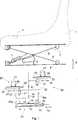
In
Mittels eines Scherengestelles mit den Scherenarmen
Eine erste Regelungseinrichtung
Das kolbenartige Element
An einer Eingangsöffnung
Ein weiterer Ein- und Ausgang
Je nachdem, wo das kolbenartige Element
Eine zweite Regelungseinrichtung
Zusammenwirkend mit der Zahnstange
Ebenso ist eine dritte Regelungseinrichtung
Auch eine Zahnstange
Sowohl das Zahnrad
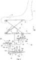
In
Gleiche und gleichbedeutende Teile sind mit gleichem Bezugszeichen versehen.Identical and equivalent parts are provided with the same reference numerals.
Dieser Darstellung ist zu entnehmen, dass der Fahrzeugsitz nach unten ausgelenkt ist, wie es durch die gestauchte bzw. zusammengedrückte Luftfeder
Zugleich wird die Feder
Ebenso hat sich das Zahnrad
Die dritte Regelungseinrichtung hingegen ist bisher unverändert.The third control device, however, is unchanged so far.
In der ersten Regelungseinrichtung
In
Dieser Darstellung ist zu entnehmen, dass nun die dritte Regelungseinrichtung
Der Pfeil
Gleichzeitig ist in der ersten Regelungseinrichtung
Nach einer derartigen Auslenkung der Zahnstange
Die Zeitspanne, innerhalb welcher der Honigmotor das Zurückkehren der Zahnstange
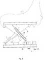
In
Dieser Darstellung ist deutlich zu entnehmen, dass die Positionierung der ersten Regelungseinrichtung
Dieses rollenartige Element
In
Dieser Zeichnung deutlich zu entnehmen, dass eine Schwingung
Wird jedoch ein oberer Hubendanschlag
Ein derartiges Zuführen von Luft anstelle des Abführens von Luft bei einer nach oben gerichteten Bewegung unmittelbar nach Erreichen des unteren Hubendanschlages und natürlich auch ein Abführen von Luft anstelle des Zuführens von Luft bei einer nach unten gerichteten Bewegung wird während einer vorbestimmbaren Zeitspanne
In dieser Darstellung sind ebenso erste und zweite Hubendbereiche
Sämtliche in den Anmeldungsunterlagen offenbarten Merkmale werden als erfindungswesentlich beansprucht, sofern sie einzeln oder in Kombination gegenüber dem Stand der Technik neu sind.All disclosed in the application documents features are claimed as essential to the invention, provided they are new individually or in combination over the prior art.
BezugszeichenlisteLIST OF REFERENCE NUMBERS
- 11
- Rückenlehnebackrest
- 22
- Sitzteilseat part
- 33
- oberes Fahrzeugsitzteilupper vehicle seat part
- 44
- unteres Fahrzeugsitzteillower vehicle seat part
- 5, 65, 6
- Scherenarmescissor arms
- 6a6a
- rollenartiges Elementroll-like element
- 77
- Dämpferdamper
- 88th
- Luftfederair spring
- 1010
- erste Regelungseinrichtungfirst control device
- 1111
- Gehäusecasing
- 1212
- kolbenartiges Elementpiston-like element
- 1313
- Doppelpfeildouble arrow
- 13b13b
- Pfeilarrow
- 14, 1514, 15
- Abdichtungselementesealing elements
- 1616
- Eingangsöffnungentrance opening
- 16a16a
- Luftair
- 1717
- Ausgangoutput
- 17a17a
- Luftair
- 1818
- Ein- und AusgangInput and output
- 1919
- Leitungmanagement
- 2020
- zweite Regelungseinrichtungsecond control device
- 20a20a
- Betätigungselementactuator
- 2121
- 2/2-Regelventil2/2-regulating valve
- 2222
- Abluftleitungexhaust duct
- 2323
- Zahnstangerack
- 2424
- Doppelpfeildouble arrow
- 24a24a
- Pfeilarrow
- 2525
- Federfeather
- 2626
- Honigmotorhoney engine
- 2727
- Doppelpfeildouble arrow
- 27a27a
- Pfeilarrow
- 3030
- dritte Regelungseinrichtungthird control device
- 30a30a
- Betätigungselementactuator
- 3131
- 2/2-Regelventil2/2-regulating valve
- 3232
- Zuluftleitungair supply
- 3333
- Zahnstangerack
- 3434
- Doppelpfeildouble arrow
- 34a34a
- Pfeilarrow
- 3535
- Federfeather
- 3636
- Zahnradgear
- 3737
- Doppelpfeildouble arrow
- 37a37a
- Pfeilarrow
- 4040
- VentilValve
- 4141
- Rückschlagventilcheck valve
- 5050
- Schwingungvibration
- 5151
- Nullliniezero line
- 52, 5352, 53
- Linieline
- 5454
- oberer Hubendanschlagupper stroke end stop
- 55, 5855, 58
- unterer Hubendanschlaglower stroke end stop
- 56, 5756, 57
- Pfeilarrow
- 5959
- Kurvenabschnittcurve section
- 6060
- Linieline
- 6161
- vorbestimmbaren Zeitspannepredeterminable time span
- 62, 6362, 63
- erste und zweite Hubendbereichefirst and second Hubendbereiche
Claims (10)
Translated fromGermanPriority Applications (3)
| Application Number | Priority Date | Filing Date | Title |
|---|---|---|---|
| DE102010022959ADE102010022959A1 (en) | 2010-06-08 | 2010-06-08 | Pneumatic suspension systems for vehicles and methods for pneumatic suspension of vehicle parts |
| EP11168453.6AEP2394843B1 (en) | 2010-06-08 | 2011-06-01 | Pneumatic suspension system for vehicles and method for pneumatic suspension of vehicle sections |
| US13/155,221US8757600B2 (en) | 2010-06-08 | 2011-06-07 | Pneumatic springing system for vehicles and method for pneumatic springing of vehicle parts |
Applications Claiming Priority (1)
| Application Number | Priority Date | Filing Date | Title |
|---|---|---|---|
| DE102010022959ADE102010022959A1 (en) | 2010-06-08 | 2010-06-08 | Pneumatic suspension systems for vehicles and methods for pneumatic suspension of vehicle parts |
Publications (1)
| Publication Number | Publication Date |
|---|---|
| DE102010022959A1true DE102010022959A1 (en) | 2011-12-08 |
Family
ID=44118135
Family Applications (1)
| Application Number | Title | Priority Date | Filing Date |
|---|---|---|---|
| DE102010022959AWithdrawnDE102010022959A1 (en) | 2010-06-08 | 2010-06-08 | Pneumatic suspension systems for vehicles and methods for pneumatic suspension of vehicle parts |
Country Status (3)
| Country | Link |
|---|---|
| US (1) | US8757600B2 (en) |
| EP (1) | EP2394843B1 (en) |
| DE (1) | DE102010022959A1 (en) |
Cited By (2)
| Publication number | Priority date | Publication date | Assignee | Title |
|---|---|---|---|---|
| CN110236324A (en)* | 2019-04-11 | 2019-09-17 | 杨松 | Vibrating bed legs, electric bed and control method for electric bed |
| DE102018126404A1 (en)* | 2018-10-23 | 2020-04-23 | Grammer Ag | Vehicle seat with residual travel control |
Families Citing this family (19)
| Publication number | Priority date | Publication date | Assignee | Title |
|---|---|---|---|---|
| ES2524942T3 (en)* | 2009-11-20 | 2014-12-15 | La Nacion, Ministerio De Defensa, Fuerza Aerea Colombiana | Vibration reduction device on the helicopter pilot's chair |
| DE102013104926A1 (en)* | 2013-05-14 | 2014-11-20 | Grammer Ag | Vehicle vibration device, vehicle seat and vehicle cabin |
| DE102013110370B4 (en) | 2013-06-04 | 2014-12-11 | Grammer Ag | vehicle seat |
| DE102013106709A1 (en)* | 2013-06-26 | 2014-12-31 | Grammer Ag | Device with a suspension system |
| DE102013110924B4 (en) | 2013-10-01 | 2018-02-08 | Grammer Ag | Vehicle with force-controlled damper with control valve |
| DE102013110920B4 (en) | 2013-10-01 | 2018-08-16 | Grammer Ag | Vehicle seat with force-controlled damper (2-pipe damper) |
| DE102013110927B4 (en)* | 2013-10-01 | 2020-09-03 | Grammer Aktiengesellschaft | Vehicle seat or vehicle cabin with a suspension device and commercial vehicle |
| DE102013110923B4 (en) | 2013-10-01 | 2019-07-04 | Grammer Ag | Vehicle seat or vehicle cabin with a suspension device and utility vehicle |
| DE102013110919B4 (en) | 2013-10-01 | 2018-08-02 | Grammer Ag | shock absorber |
| DE102013110926B4 (en)* | 2013-10-01 | 2019-09-05 | Grammer Aktiengesellschaft | Vehicle seat or vehicle cabin with a suspension device and utility vehicle |
| DE102013021561B4 (en) | 2013-12-16 | 2020-09-03 | Grammer Ag | Vehicle seat with a horizontally movable seat surface to accommodate a person |
| DE102014109191B8 (en)* | 2014-07-01 | 2018-12-20 | Grammer Aktiengesellschaft | Suspension system for vehicle seats and method for springing vehicle seat parts |
| DE102015113176B4 (en)* | 2015-08-10 | 2021-12-30 | Grammer Aktiengesellschaft | Horizontal vibration device for a vehicle seat |
| FR3054535B1 (en) | 2016-07-28 | 2020-06-26 | Universite Clermont Auvergne | LIFT SYSTEM FOR MOUNTING OR LOWERING A PLATFORM |
| EP3732074A4 (en) | 2017-12-27 | 2021-10-20 | Ergoair, Inc. | Pneumatic seat support |
| EP3807124A4 (en)* | 2018-06-15 | 2022-03-09 | Milsco, LLC | Low profile adjustable vehicle seat mount assembly |
| CN110722953B (en)* | 2019-10-18 | 2021-10-12 | 安路普(北京)汽车技术有限公司 | Method and system for adjusting damping force of damper |
| US20230211986A1 (en)* | 2022-01-05 | 2023-07-06 | Industry Sherpa, Inc. | Vertically stabilized platform |
| US12145490B2 (en)* | 2023-01-25 | 2024-11-19 | Lear Corporation | Seat vibration dampening system and method for controlling same |
Citations (3)
| Publication number | Priority date | Publication date | Assignee | Title |
|---|---|---|---|---|
| DE2753105A1 (en)* | 1977-11-29 | 1979-06-07 | Isringhausen Geb | AIR-SUSPENSION VEHICLE SEAT |
| US4946145A (en)* | 1989-08-29 | 1990-08-07 | Tachi-S Co., Ltd. | Air suspension device for vehicle seat |
| DE102005051228A1 (en)* | 2005-10-26 | 2007-05-03 | Grammer Ag | Oscillation damping height adjusting device for vehicle seat, has converting unit connected with rotating unit to delay and limit rotating movement to maximum rotating speed value with spring frequency which lies above threshold value |
Family Cites Families (17)
| Publication number | Priority date | Publication date | Assignee | Title |
|---|---|---|---|---|
| FR2409880B1 (en) | 1977-11-29 | 1986-04-25 | Pietsch Helge | VEHICLE SUSPENDED SEAT |
| DE3517505A1 (en)* | 1985-05-15 | 1986-11-20 | Grammer Sitzsysteme GmbH, 8450 Amberg | CUSHIONED SEAT |
| DE4025183C1 (en)* | 1990-08-09 | 1991-11-14 | Grammer Ag, 8450 Amberg, De | |
| DE4335199C1 (en)* | 1993-10-15 | 1995-05-11 | Grammer Ag | Vehicle seat with spring suspension |
| US5975508A (en)* | 1995-09-06 | 1999-11-02 | Applied Power Inc. | Active vehicle seat suspension system |
| US5735509A (en)* | 1996-02-08 | 1998-04-07 | Sears Manufacturing Company | Seat suspension assembly |
| DE10301417A1 (en)* | 2003-01-16 | 2004-08-12 | Airbus Deutschland Gmbh | Mechanism for operating an aircraft valve |
| EP1468870B1 (en)* | 2003-04-14 | 2006-06-07 | Grammer Ag | Device and method for the suspension of a vehicle seat. |
| DE10317134B3 (en) | 2003-04-14 | 2004-06-24 | Grammer Ag | Spring suspension device for commercial vehicle seat, uses air spring with different gradient of force/displacement spring characteristic in different ranges |
| ITPR20030059A1 (en)* | 2003-07-23 | 2005-01-24 | Biffi Italia | SUBMARINE ACTUATOR WITH SIMPLE EFFECT FOR MANEUVERING |
| DE102005023088B3 (en)* | 2005-05-13 | 2006-06-22 | Grammer Ag | Suspension for e.g. tractor seat, has controller, where removal and discharging of additional volumes is switched on or deactivated by controller so that distribution of force path spring characteristic line has no or small gradient |
| DE102005023090B4 (en)* | 2005-05-13 | 2009-04-09 | Grammer Ag | Device and method for suspension of a vehicle cabin by means of additional volumes |
| DE202007002243U1 (en)* | 2007-02-15 | 2007-04-19 | Festo Ag & Co | Height adjusting device for a vehicle seat comprises control connecting links arranged on a control carriage which moves linearly in the direction of a linear switching movement |
| DE102007056700B4 (en) | 2007-11-24 | 2012-03-29 | Grammer Aktiengesellschaft | Device with a suspension system and method for adjusting a suspension system |
| DE102008022045B3 (en)* | 2008-05-03 | 2009-07-30 | Grammer Ag | Vehicle seat has device for controlling pneumatically controlled suspension system, by which vehicle seat is supported against vehicle body part |
| DE102008050192B4 (en)* | 2008-09-03 | 2015-10-29 | Grammer Aktiengesellschaft | Vehicle vibration damping system |
| DE102009005381B4 (en)* | 2009-01-21 | 2013-05-08 | Grammer Aktiengesellschaft | Device for springing a mass and method for adjusting and / or operating a fluid spring |
- 2010
- 2010-06-08DEDE102010022959Apatent/DE102010022959A1/ennot_activeWithdrawn
- 2011
- 2011-06-01EPEP11168453.6Apatent/EP2394843B1/enactiveActive
- 2011-06-07USUS13/155,221patent/US8757600B2/enactiveActive
Patent Citations (3)
| Publication number | Priority date | Publication date | Assignee | Title |
|---|---|---|---|---|
| DE2753105A1 (en)* | 1977-11-29 | 1979-06-07 | Isringhausen Geb | AIR-SUSPENSION VEHICLE SEAT |
| US4946145A (en)* | 1989-08-29 | 1990-08-07 | Tachi-S Co., Ltd. | Air suspension device for vehicle seat |
| DE102005051228A1 (en)* | 2005-10-26 | 2007-05-03 | Grammer Ag | Oscillation damping height adjusting device for vehicle seat, has converting unit connected with rotating unit to delay and limit rotating movement to maximum rotating speed value with spring frequency which lies above threshold value |
Cited By (4)
| Publication number | Priority date | Publication date | Assignee | Title |
|---|---|---|---|---|
| DE102018126404A1 (en)* | 2018-10-23 | 2020-04-23 | Grammer Ag | Vehicle seat with residual travel control |
| DE102018126404B4 (en)* | 2018-10-23 | 2021-02-25 | Grammer Aktiengesellschaft | Vehicle seat with residual spring travel control |
| US11192476B2 (en) | 2018-10-23 | 2021-12-07 | Grammer Ag | Vehicle seat having a residual spring travel controller |
| CN110236324A (en)* | 2019-04-11 | 2019-09-17 | 杨松 | Vibrating bed legs, electric bed and control method for electric bed |
Also Published As
| Publication number | Publication date |
|---|---|
| US8757600B2 (en) | 2014-06-24 |
| EP2394843A3 (en) | 2013-08-28 |
| EP2394843A2 (en) | 2011-12-14 |
| EP2394843B1 (en) | 2014-10-08 |
| US20110298266A1 (en) | 2011-12-08 |
Similar Documents
| Publication | Publication Date | Title |
|---|---|---|
| EP2394843B1 (en) | Pneumatic suspension system for vehicles and method for pneumatic suspension of vehicle sections | |
| DE102008052960B4 (en) | Suspension vibration system for vibration reduction | |
| DE102014001890B4 (en) | Device for cushioning a suspension upper part in at least one spatial direction relative to a relatively movable lower suspension part, seat and vehicle with such a device | |
| DE102010026569B4 (en) | Control device for reducing a vibration movement of a spring-loaded oscillating device | |
| DE102008016685B3 (en) | Vehicle seat has height adjustable seat frame, which has two seat frame sections moved relative to each other, and valve unit has inertia element for temporary supply and discharge of fluid flow | |
| EP1721779B1 (en) | Device and method for damping a vehicle seat by means of the additional volume | |
| DE60320456T2 (en) | ADJUSTABLE DAMPING CONTROL WITH END STOP | |
| DE102017115347B4 (en) | Vehicle seat with adjustable damper and commercial vehicle | |
| DE102005011856B3 (en) | Seat with horizontal suspension for vehicle has a vertical or pneumatic shock absorber of vertical system connected to that of the horizontal system | |
| EP1327539B1 (en) | Air spring strut | |
| DE102015121764B4 (en) | vehicle vibration device | |
| DE102006016047B3 (en) | Spring system for vehicle seating, has spring and shock absorber arranged between swinging part and fixed part, and damping force of shock absorber rises progressively with rising speed of swinging part with respect to fixed part | |
| DE102010046489B3 (en) | Vehicle seat, in particular commercial vehicle seat | |
| DE2736026A1 (en) | ADJUSTABLE WHEEL SUSPENSION SYSTEM FOR VEHICLES | |
| DE102013106709A1 (en) | Device with a suspension system | |
| EP2861439A1 (en) | Adjustable wheel suspension for the wheels of an axle of a motor vehicle | |
| DE3403649A1 (en) | Wheel suspension system for motor vehicles and other vehicles | |
| EP2619031B1 (en) | Vehicle seat, in particular commercial vehicle seat | |
| DE19902224C1 (en) | Motor vehicle seat has sprung lower part on a base part, two-arm lever attached to base part carrying wt. on one arm and actuating switch with other arm to adjust seat damping characteristic | |
| DE102014114861A1 (en) | A vehicle suspension device comprising a rod and a body load reaction component for controlling ground clearance | |
| DE2745768A1 (en) | HYDRAULIC SHOCK ABSORBER | |
| DE1802474A1 (en) | Cushioned seat suspension for vehicles of all kinds, in particular motor vehicles or work machines | |
| DE2721926A1 (en) | SUSPENSION FOR A VEHICLE SEAT | |
| WO2020225029A1 (en) | Stabilizer assembly for a two-track vehicle | |
| DE102015200383B4 (en) | Damper unit for a suspension system with a semi-active damping means |
Legal Events
| Date | Code | Title | Description |
|---|---|---|---|
| R016 | Response to examination communication | ||
| R016 | Response to examination communication | ||
| R016 | Response to examination communication | ||
| R016 | Response to examination communication | ||
| R119 | Application deemed withdrawn, or ip right lapsed, due to non-payment of renewal fee |