DE102010020418A1 - Apparatus and method for the generative production of a three-dimensional object with construction panel boundary - Google Patents
Apparatus and method for the generative production of a three-dimensional object with construction panel boundaryDownload PDFInfo
- Publication number
- DE102010020418A1 DE102010020418A1DE102010020418ADE102010020418ADE102010020418A1DE 102010020418 A1DE102010020418 A1DE 102010020418A1DE 102010020418 ADE102010020418 ADE 102010020418ADE 102010020418 ADE102010020418 ADE 102010020418ADE 102010020418 A1DE102010020418 A1DE 102010020418A1
- Authority
- DE
- Germany
- Prior art keywords
- construction field
- maximum
- powder material
- layer
- coater
- Prior art date
- Legal status (The legal status is an assumption and is not a legal conclusion. Google has not performed a legal analysis and makes no representation as to the accuracy of the status listed.)
- Ceased
Links
- 238000010276constructionMethods0.000titleclaimsabstractdescription80
- 238000000034methodMethods0.000titleclaimsabstractdescription23
- 238000004519manufacturing processMethods0.000titleclaimsabstractdescription7
- 239000000843powderSubstances0.000claimsabstractdescription65
- 239000000463materialSubstances0.000claimsabstractdescription50
- 238000007711solidificationMethods0.000claimsdescription6
- 230000008023solidificationEffects0.000claimsdescription6
- 230000005855radiationEffects0.000abstractdescription5
- 238000000149argon plasma sinteringMethods0.000description10
- 238000000576coating methodMethods0.000description4
- 239000011248coating agentSubstances0.000description3
- 229910052751metalInorganic materials0.000description3
- 239000002184metalSubstances0.000description3
- 238000011161developmentMethods0.000description2
- 230000018109developmental processEffects0.000description2
- 239000002245particleSubstances0.000description2
- 229920006260polyaryletherketonePolymers0.000description2
- 229920000642polymerPolymers0.000description2
- BUHVIAUBTBOHAG-FOYDDCNASA-N(2r,3r,4s,5r)-2-[6-[[2-(3,5-dimethoxyphenyl)-2-(2-methylphenyl)ethyl]amino]purin-9-yl]-5-(hydroxymethyl)oxolane-3,4-diolChemical compoundCOC1=CC(OC)=CC(C(CNC=2C=3N=CN(C=3N=CN=2)[C@H]2[C@@H]([C@H](O)[C@@H](CO)O2)O)C=2C(=CC=CC=2)C)=C1BUHVIAUBTBOHAG-FOYDDCNASA-N0.000description1
- 229910000831SteelInorganic materials0.000description1
- 239000000853adhesiveSubstances0.000description1
- 230000001070adhesive effectEffects0.000description1
- 239000000956alloySubstances0.000description1
- 229910045601alloyInorganic materials0.000description1
- 239000011230binding agentSubstances0.000description1
- 239000004566building materialSubstances0.000description1
- 239000000919ceramicSubstances0.000description1
- 239000002131composite materialSubstances0.000description1
- 230000001419dependent effectEffects0.000description1
- 238000010894electron beam technologyMethods0.000description1
- 150000002739metalsChemical class0.000description1
- 239000000203mixtureSubstances0.000description1
- 238000012986modificationMethods0.000description1
- 230000004048modificationEffects0.000description1
- 239000004033plasticSubstances0.000description1
- 229920001652poly(etherketoneketone)Polymers0.000description1
- 230000001681protective effectEffects0.000description1
- 239000004576sandSubstances0.000description1
- 239000010959steelSubstances0.000description1
- 239000002699waste materialSubstances0.000description1
Images


Classifications
- B—PERFORMING OPERATIONS; TRANSPORTING
- B29—WORKING OF PLASTICS; WORKING OF SUBSTANCES IN A PLASTIC STATE IN GENERAL
- B29C—SHAPING OR JOINING OF PLASTICS; SHAPING OF MATERIAL IN A PLASTIC STATE, NOT OTHERWISE PROVIDED FOR; AFTER-TREATMENT OF THE SHAPED PRODUCTS, e.g. REPAIRING
- B29C64/00—Additive manufacturing, i.e. manufacturing of three-dimensional [3D] objects by additive deposition, additive agglomeration or additive layering, e.g. by 3D printing, stereolithography or selective laser sintering
- B29C64/10—Processes of additive manufacturing
- B29C64/141—Processes of additive manufacturing using only solid materials
- B29C64/153—Processes of additive manufacturing using only solid materials using layers of powder being selectively joined, e.g. by selective laser sintering or melting
- B—PERFORMING OPERATIONS; TRANSPORTING
- B22—CASTING; POWDER METALLURGY
- B22F—WORKING METALLIC POWDER; MANUFACTURE OF ARTICLES FROM METALLIC POWDER; MAKING METALLIC POWDER; APPARATUS OR DEVICES SPECIALLY ADAPTED FOR METALLIC POWDER
- B22F10/00—Additive manufacturing of workpieces or articles from metallic powder
- B22F10/20—Direct sintering or melting
- B22F10/28—Powder bed fusion, e.g. selective laser melting [SLM] or electron beam melting [EBM]
- B—PERFORMING OPERATIONS; TRANSPORTING
- B22—CASTING; POWDER METALLURGY
- B22F—WORKING METALLIC POWDER; MANUFACTURE OF ARTICLES FROM METALLIC POWDER; MAKING METALLIC POWDER; APPARATUS OR DEVICES SPECIALLY ADAPTED FOR METALLIC POWDER
- B22F10/00—Additive manufacturing of workpieces or articles from metallic powder
- B22F10/40—Structures for supporting workpieces or articles during manufacture and removed afterwards
- B—PERFORMING OPERATIONS; TRANSPORTING
- B22—CASTING; POWDER METALLURGY
- B22F—WORKING METALLIC POWDER; MANUFACTURE OF ARTICLES FROM METALLIC POWDER; MAKING METALLIC POWDER; APPARATUS OR DEVICES SPECIALLY ADAPTED FOR METALLIC POWDER
- B22F12/00—Apparatus or devices specially adapted for additive manufacturing; Auxiliary means for additive manufacturing; Combinations of additive manufacturing apparatus or devices with other processing apparatus or devices
- B22F12/22—Driving means
- B22F12/222—Driving means for motion along a direction orthogonal to the plane of a layer
- B—PERFORMING OPERATIONS; TRANSPORTING
- B29—WORKING OF PLASTICS; WORKING OF SUBSTANCES IN A PLASTIC STATE IN GENERAL
- B29C—SHAPING OR JOINING OF PLASTICS; SHAPING OF MATERIAL IN A PLASTIC STATE, NOT OTHERWISE PROVIDED FOR; AFTER-TREATMENT OF THE SHAPED PRODUCTS, e.g. REPAIRING
- B29C64/00—Additive manufacturing, i.e. manufacturing of three-dimensional [3D] objects by additive deposition, additive agglomeration or additive layering, e.g. by 3D printing, stereolithography or selective laser sintering
- B29C64/20—Apparatus for additive manufacturing; Details thereof or accessories therefor
- B29C64/255—Enclosures for the building material, e.g. powder containers
- B29C64/259—Interchangeable
- B—PERFORMING OPERATIONS; TRANSPORTING
- B33—ADDITIVE MANUFACTURING TECHNOLOGY
- B33Y—ADDITIVE MANUFACTURING, i.e. MANUFACTURING OF THREE-DIMENSIONAL [3-D] OBJECTS BY ADDITIVE DEPOSITION, ADDITIVE AGGLOMERATION OR ADDITIVE LAYERING, e.g. BY 3-D PRINTING, STEREOLITHOGRAPHY OR SELECTIVE LASER SINTERING
- B33Y10/00—Processes of additive manufacturing
- B—PERFORMING OPERATIONS; TRANSPORTING
- B33—ADDITIVE MANUFACTURING TECHNOLOGY
- B33Y—ADDITIVE MANUFACTURING, i.e. MANUFACTURING OF THREE-DIMENSIONAL [3-D] OBJECTS BY ADDITIVE DEPOSITION, ADDITIVE AGGLOMERATION OR ADDITIVE LAYERING, e.g. BY 3-D PRINTING, STEREOLITHOGRAPHY OR SELECTIVE LASER SINTERING
- B33Y30/00—Apparatus for additive manufacturing; Details thereof or accessories therefor
- Y—GENERAL TAGGING OF NEW TECHNOLOGICAL DEVELOPMENTS; GENERAL TAGGING OF CROSS-SECTIONAL TECHNOLOGIES SPANNING OVER SEVERAL SECTIONS OF THE IPC; TECHNICAL SUBJECTS COVERED BY FORMER USPC CROSS-REFERENCE ART COLLECTIONS [XRACs] AND DIGESTS
- Y02—TECHNOLOGIES OR APPLICATIONS FOR MITIGATION OR ADAPTATION AGAINST CLIMATE CHANGE
- Y02P—CLIMATE CHANGE MITIGATION TECHNOLOGIES IN THE PRODUCTION OR PROCESSING OF GOODS
- Y02P10/00—Technologies related to metal processing
- Y02P10/25—Process efficiency
Landscapes
- Engineering & Computer Science (AREA)
- Chemical & Material Sciences (AREA)
- Materials Engineering (AREA)
- Manufacturing & Machinery (AREA)
- Physics & Mathematics (AREA)
- Mechanical Engineering (AREA)
- Optics & Photonics (AREA)
- Plasma & Fusion (AREA)
- Powder Metallurgy (AREA)
Abstract
Translated fromGermanDescription
Translated fromGermanDie vorliegende Erfindung bezieht sich auf eine Vorrichtung und auf ein Verfahren zum generativen Herstellen eines dreidimensionalen Objekts.The present invention relates to an apparatus and method for generatively producing a three-dimensional object.
Im oberen Abschnitt des Rahmens ist ein zweidimensionales, maximales Baufeld mit einer maximalen Länge und einer maximalen Breite definiert, in dem das Pulvermaterial aufgetragen und bestrahlt werden kann. In vertikaler Richtung bestimmt die Höhe des größten Objekts die minimale Höhe pro Bauvorgang. Aus den drei Maßen, nämlich der maximalen Länge, der maximalen Breite und der minimalen Höhe pro Bauvorgang ergibt sich das Mindestbauvolumen, und mit den Pulverbett- und Bauteildichten lässt sich die Menge des erforderlichen Pulvermaterials errechnen.In the upper part of the frame is defined a two-dimensional, maximum construction field with a maximum length and a maximum width, in which the powder material can be applied and irradiated. In the vertical direction, the height of the largest object determines the minimum height per construction process. From the three dimensions, namely the maximum length, the maximum width and the minimum height per construction process, the minimum construction volume is obtained, and with the powder bed and component densities, the amount of powder material required can be calculated.
Wenn nur eine geringe Menge an Pulvermaterial vorliegt oder der Materialeinsatz aus Kostengründen gering gehalten werden muss, ist bei einer großen Fläche des Trägers nur eine sehr geringe Höhe des Bauvorgangs möglich. Die Situation wird insbesondere dadurch verschärft, dass das nicht-verfestigte Pulvermaterial nur teilweise oder manchmal auch gar nicht wieder verwendet werden kann. Ein Bauvorgang mit einer großen vertikalen Höhe führt dann zu großen Abfallmengen, insbesondere wenn die Objekte nicht günstig im Rahmen bzw. Baubehälter angeordnet werden können. Üblicherweise kann das verbrauchte Pulver nur zum Teil wieder verwendet werden.If only a small amount of powder material is present or the use of materials must be kept low for cost reasons, only a very small amount of the construction process is possible with a large area of the support. The situation is aggravated in particular by the fact that the non-solidified powder material can only partially or sometimes not be reused. A construction process with a large vertical height then leads to large amounts of waste, especially if the objects can not be conveniently located in the frame or building container. Usually, the used powder can only be partially used again.
Es ist die Aufgabe der vorliegenden Erfindung, eine Vorrichtung und ein Verfahren zum generativen Herstellen eines dreidimensionalen Objekts vorzusehen, mit denen eine größere Flexibilität bei der Verwendung der Vorrichtung sowie eine wirtschaftliche Nutzung des Pulvers bei kleinen Objekten und bei der Verarbeitung von kostenintensiven und nicht-recycelbaren Pulvermaterialien ermöglicht werden. Außerdem soll es möglich sein, die Entwicklung von Pulvermaterialien auch für große Vorrichtungen flexibel und wirtschaftlich zu gestalten. Diese Aufgabe wird durch die Vorrichtung mit den Merkmalen des Anspruchs 1 und durch das Verfahren mit den Merkmalen des Anspruchs 4 gelöst. Vorteilhafte Weiterbildungen sind Gegenstand der Unteransprüche.It is the object of the present invention to provide an apparatus and a method for generatively producing a three-dimensional object, with which a greater flexibility in the use of the device and an economic use of the powder in small objects and in the processing of costly and non-recyclable Powder materials are made possible. In addition, it should be possible to make the development of powder materials for large devices flexible and economical. This object is achieved by the device having the features of claim 1 and by the method having the features of claim 4. Advantageous developments are the subject of the dependent claims.
Die Erfindung hat den Vorteil, dass auch kleine Objekte in einer großen Lasersinteranlage wirtschaftlich hergestellt werden können, da nur die minimal benötigte Pulvermenge eingesetzt wird. Darüber hinaus ergibt sich die Möglichkeit, mit wenig Pulvermaterial den Bauprozess unter den thermischen Bedingungen einer großen Lasersinteranlage zu untersuchen. Insbesondere bietet sich die Anwendung der Erfindung bei PAEK-Pulvern, wie z. B. PEEK, PEKK, etc, als Baumaterial an. Gerade diese Polymerpulver, die, nicht nur aufgrund der hohen Temperaturstabilität, zu vielversprechenden Eigenschaften der hergestellten Objekte führen, sind nur sehr eingeschränkt recycelbar und darüberhinaus zur Zeit noch ziemlich teuer.The invention has the advantage that even small objects in a large laser sintering plant can be produced economically, since only the minimum amount of powder required is used. In addition, there is the possibility to investigate the building process under the thermal conditions of a large laser sintering plant with little powder material. In particular, the application of the invention in PAEK powders, such as. B. PEEK, PEKK, etc, as a building material. It is precisely these polymer powders which, not only because of the high temperature stability, lead to promising properties of the objects produced, are only very limited in their recyclability and, moreover, are still rather expensive at the moment.
Weitere Merkmale und Zweckmäßigkeiten der Erfindung ergeben sich aus der Beschreibung von Ausführungsbeispielen anhand der beigefügten Zeichnungen. Von den Figuren zeigen:Further features and advantages of the invention will become apparent from the description of embodiments with reference to the accompanying drawings. From the figures show:
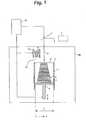
Die
Die Lasersintervorrichtung weist einen nach oben hin offenen Rahmen
Des Weiteren ist ein Beschichter
Der Beschichter
Die Vorrichtung weist des Weiteren eine Verfestigungsvorrichtung in Gestalt eines Lasers
Die Lasersintervorrichtung kann eine Heizvorrichtung (nicht gezeigt) oberhalb des Baufelds
Mit dem Bezugszeichen
Das Baufeld
Falls kleine Objekte
Bei dem Betrieb der Vorrichtung wird in einem ersten Schritt der Träger
Das erfindungsgemäße Verfahren hat eine normale Betriebsweise, bei der das Pulvermaterial
Falls kleine Objekte
Da sich das reduzierte Baufeld
Vorzugsweise ist das reduzierte Baufeld
Ein Bauvorgang unter Verwendung der speziellen Betriebsweise mit reduziertem Baufeld läuft folgendermaßen ab:
Nachdem das Pulvermaterial
After the
In einem nächsten Schritt wird dann der Träger
Da die Steuereinheit
Der Schutzumfang beschränkt sich nicht auf die dargestellten Ausführungsbeispiele, sondern er umfasst weitere Änderungen und Abwandlungen, sofern diese innerhalb des durch die beigefügten Ansprüche definierten Umfangs fallen.The scope of protection is not limited to the illustrated embodiments, but it includes other changes and modifications, provided that they fall within the scope defined by the appended claims.
Im dargestellten Ausführungsbeispiel werden ein rechteckiges maximales Baufeld
Im dargestellten Ausführungsbeispiel werden die Stützwände
Die erfindungsgemäße Vorrichtung ist nicht nur beim Lasersintern anwendbar, sondern auf alle pulverbasierten, generativen Verfahren, bei denen pro aufzutragender Schicht ein Werkstoff bzw. ein Pulvermaterial verwendet wird, welches zum Beispiel durch die energiehaltige Strahlung verfestigt wird. Die energiehaltige Strahlung muss nicht unbedingt ein Laserstrahl
ZITATE ENTHALTEN IN DER BESCHREIBUNG QUOTES INCLUDE IN THE DESCRIPTION
Diese Liste der vom Anmelder aufgeführten Dokumente wurde automatisiert erzeugt und ist ausschließlich zur besseren Information des Lesers aufgenommen. Die Liste ist nicht Bestandteil der deutschen Patent- bzw. Gebrauchsmusteranmeldung. Das DPMA übernimmt keinerlei Haftung für etwaige Fehler oder Auslassungen.This list of the documents listed by the applicant has been generated automatically and is included solely for the better information of the reader. The list is not part of the German patent or utility model application. The DPMA assumes no liability for any errors or omissions.
Zitierte PatentliteraturCited patent literature
- DE 19937260 B4[0002]DE 19937260 B4[0002]
Claims (6)
Translated fromGermanPriority Applications (5)
| Application Number | Priority Date | Filing Date | Title |
|---|---|---|---|
| DE102010020418ADE102010020418A1 (en) | 2010-05-12 | 2010-05-12 | Apparatus and method for the generative production of a three-dimensional object with construction panel boundary |
| EP11164272.4AEP2386405B1 (en) | 2010-05-12 | 2011-04-29 | Device for generative manufacturing of a three dimensional object with restricted construction area |
| JP2011105446AJP2011251529A (en) | 2010-05-12 | 2011-05-10 | Device and method of generatively manufacturing three-dimensional object with working field limitation |
| US13/106,037US20110278773A1 (en) | 2010-05-12 | 2011-05-12 | Device And Method Of Generatively Manufacturing A Three-Dimensional Object With Working Field Limitation |
| CN201110122072XACN102240806A (en) | 2010-05-12 | 2011-05-12 | Device and method for generative manufacturing of a three dimensional object with construction area limit |
Applications Claiming Priority (1)
| Application Number | Priority Date | Filing Date | Title |
|---|---|---|---|
| DE102010020418ADE102010020418A1 (en) | 2010-05-12 | 2010-05-12 | Apparatus and method for the generative production of a three-dimensional object with construction panel boundary |
Publications (1)
| Publication Number | Publication Date |
|---|---|
| DE102010020418A1true DE102010020418A1 (en) | 2011-11-17 |
Family
ID=44242759
Family Applications (1)
| Application Number | Title | Priority Date | Filing Date |
|---|---|---|---|
| DE102010020418ACeasedDE102010020418A1 (en) | 2010-05-12 | 2010-05-12 | Apparatus and method for the generative production of a three-dimensional object with construction panel boundary |
Country Status (5)
| Country | Link |
|---|---|
| US (1) | US20110278773A1 (en) |
| EP (1) | EP2386405B1 (en) |
| JP (1) | JP2011251529A (en) |
| CN (1) | CN102240806A (en) |
| DE (1) | DE102010020418A1 (en) |
Cited By (5)
| Publication number | Priority date | Publication date | Assignee | Title |
|---|---|---|---|---|
| DE102015213103A1 (en) | 2015-07-13 | 2017-01-19 | Eos Gmbh Electro Optical Systems | Method and device for producing a three-dimensional object |
| DE102018122296A1 (en)* | 2018-09-12 | 2020-03-12 | Codronic Gmbh | Method and device for additive manufacturing of a component with a support structure |
| DE112012006355B4 (en) | 2012-05-11 | 2023-05-11 | Arcam Ab | Powder distribution in additive manufacturing |
| DE102015218753B4 (en) | 2015-09-29 | 2024-07-25 | KSB SE & Co. KGaA | Process for producing a component |
| DE102011121568B4 (en)* | 2011-12-20 | 2025-06-18 | Concept Laser Gmbh | Process and production of three-dimensional objects by successive solidification of layers of a powdered building material |
Families Citing this family (59)
| Publication number | Priority date | Publication date | Assignee | Title |
|---|---|---|---|---|
| DE102010019447A1 (en)* | 2010-05-05 | 2011-11-10 | Eos Gmbh Electro Optical Systems | A method for generatively producing a three-dimensional object with reamers and method for creating a corresponding dataset |
| DE102010020416A1 (en)* | 2010-05-12 | 2011-11-17 | Eos Gmbh Electro Optical Systems | Construction space changing device and a device for producing a three-dimensional object with a construction space changing device |
| DE102011079521A1 (en)* | 2011-07-21 | 2013-01-24 | Evonik Degussa Gmbh | Improved component properties through beam shaping in laser sintering |
| DE102011079518A1 (en)* | 2011-07-21 | 2013-01-24 | Evonik Degussa Gmbh | Improved component properties through optimized process control in laser sintering |
| JP2014125643A (en)* | 2012-12-25 | 2014-07-07 | Honda Motor Co Ltd | Apparatus for three-dimensional shaping and method for three-dimensional shaping |
| US20140246809A1 (en)* | 2013-03-04 | 2014-09-04 | California Institute Of Technology | Systems and methods implementing additive manufacturing processes that utilize multiple build heads |
| EP2969485B1 (en) | 2013-03-15 | 2019-06-05 | 3D Systems, Inc. | Chute for laser sintering systems |
| CN104416902B (en) | 2013-08-23 | 2017-03-01 | 三纬国际立体列印科技股份有限公司 | Three-dimensional printing device |
| CN103498141B (en)* | 2013-09-03 | 2016-02-17 | 航天特种材料及工艺技术研究所 | A kind of superalloy muscle rib structure laser solid forming method |
| US20160303798A1 (en)* | 2013-12-20 | 2016-10-20 | United Technologies Corporation | Method and device for manufacturing of three dimensional objects utilizing direct plasma arc |
| JP5717900B1 (en)* | 2014-05-15 | 2015-05-13 | 株式会社ソディック | Manufacturing equipment for three-dimensional layered objects |
| US9486878B2 (en) | 2014-06-20 | 2016-11-08 | Velo3D, Inc. | Apparatuses, systems and methods for three-dimensional printing |
| GB201417687D0 (en) | 2014-10-07 | 2014-11-19 | Renishaw Plc | A module for additive manufacturing apparatus |
| DE102015109525A1 (en)* | 2015-06-15 | 2016-12-15 | Cl Schutzrechtsverwaltungs Gmbh | Apparatus for producing three-dimensional objects and an associated method |
| US10814387B2 (en)* | 2015-08-03 | 2020-10-27 | General Electric Company | Powder recirculating additive manufacturing apparatus and method |
| US10065270B2 (en) | 2015-11-06 | 2018-09-04 | Velo3D, Inc. | Three-dimensional printing in real time |
| JP6477428B2 (en)* | 2015-11-09 | 2019-03-06 | トヨタ自動車株式会社 | Control method of additive manufacturing apparatus |
| US10286603B2 (en) | 2015-12-10 | 2019-05-14 | Velo3D, Inc. | Skillful three-dimensional printing |
| JP6167195B2 (en)* | 2016-02-10 | 2017-07-19 | 本田技研工業株式会社 | 3D modeling apparatus and 3D modeling method |
| US10549478B2 (en)* | 2016-02-11 | 2020-02-04 | General Electric Company | Methods and surrounding supports for additive manufacturing |
| US20170239719A1 (en) | 2016-02-18 | 2017-08-24 | Velo3D, Inc. | Accurate three-dimensional printing |
| EP3492244A1 (en) | 2016-06-29 | 2019-06-05 | VELO3D, Inc. | Three-dimensional printing system and method for three-dimensional printing |
| US11691343B2 (en) | 2016-06-29 | 2023-07-04 | Velo3D, Inc. | Three-dimensional printing and three-dimensional printers |
| WO2018017082A1 (en)* | 2016-07-20 | 2018-01-25 | Hewlett-Packard Development Company, L.P. | Printing three-dimensional (3d) objects |
| JP6443410B2 (en) | 2016-08-10 | 2018-12-26 | トヨタ自動車株式会社 | 3D modeling system and 3D modeling method |
| US20180093418A1 (en) | 2016-09-30 | 2018-04-05 | Velo3D, Inc. | Three-dimensional objects and their formation |
| US20180126460A1 (en) | 2016-11-07 | 2018-05-10 | Velo3D, Inc. | Gas flow in three-dimensional printing |
| US20180186082A1 (en) | 2017-01-05 | 2018-07-05 | Velo3D, Inc. | Optics in three-dimensional printing |
| US10022795B1 (en) | 2017-01-13 | 2018-07-17 | General Electric Company | Large scale additive machine |
| US11167454B2 (en) | 2017-01-13 | 2021-11-09 | General Electric Company | Method and apparatus for continuously refreshing a recoater blade for additive manufacturing |
| US20180200962A1 (en) | 2017-01-13 | 2018-07-19 | General Electric Company | Additive manufacturing using a dynamically grown build envelope |
| US10022794B1 (en) | 2017-01-13 | 2018-07-17 | General Electric Company | Additive manufacturing using a mobile build volume |
| US10478893B1 (en) | 2017-01-13 | 2019-11-19 | General Electric Company | Additive manufacturing using a selective recoater |
| US9956612B1 (en) | 2017-01-13 | 2018-05-01 | General Electric Company | Additive manufacturing using a mobile scan area |
| US10646924B2 (en) | 2017-02-21 | 2020-05-12 | General Electric Company | Additive manufacturing using a recoater with in situ exchangeable recoater blades |
| US10315252B2 (en) | 2017-03-02 | 2019-06-11 | Velo3D, Inc. | Three-dimensional printing of three-dimensional objects |
| US10449696B2 (en) | 2017-03-28 | 2019-10-22 | Velo3D, Inc. | Material manipulation in three-dimensional printing |
| WO2018186837A1 (en)* | 2017-04-04 | 2018-10-11 | Hewlett-Packard Development Company, L.P. | Forming layers of build material |
| DE102017110650A1 (en)* | 2017-05-16 | 2018-11-22 | Ald Vacuum Technologies Gmbh | Method and device for the additive production of workpieces |
| EP3466651A1 (en)* | 2017-10-04 | 2019-04-10 | CL Schutzrechtsverwaltungs GmbH | Method for operating at least one apparatus for additively manufacturing three-dimensional objects |
| JP6939423B2 (en)* | 2017-10-31 | 2021-09-22 | 株式会社Ihi | Powder saving device and powder saving method |
| US11571743B2 (en)* | 2017-11-13 | 2023-02-07 | General Electric Company | Systems and methods for additive manufacturing |
| US10307823B1 (en) | 2017-11-13 | 2019-06-04 | General Electric Company | Methods and systems for repairing powder containment structures |
| US10272525B1 (en) | 2017-12-27 | 2019-04-30 | Velo3D, Inc. | Three-dimensional printing systems and methods of their use |
| US10144176B1 (en) | 2018-01-15 | 2018-12-04 | Velo3D, Inc. | Three-dimensional printing systems and methods of their use |
| EP3521027B1 (en)* | 2018-01-31 | 2020-10-07 | CL Schutzrechtsverwaltungs GmbH | Method for determining an amount of build material which is to be applied in a build plane and dosing device comprising a control unit using the method |
| EP3572212B1 (en)* | 2018-05-23 | 2025-10-01 | Concept Laser GmbH | Method for additively manufacturing three-dimensional objects |
| US11072039B2 (en)* | 2018-06-13 | 2021-07-27 | General Electric Company | Systems and methods for additive manufacturing |
| US11117329B2 (en) | 2018-06-26 | 2021-09-14 | General Electric Company | Additively manufactured build assemblies having reduced distortion and residual stress |
| US11440097B2 (en) | 2019-02-12 | 2022-09-13 | General Electric Company | Methods for additively manufacturing components using lattice support structures |
| JP6545411B1 (en)* | 2019-02-13 | 2019-07-17 | 株式会社松浦機械製作所 | Method of forming a three-dimensional object |
| FR3098751B1 (en) | 2019-07-19 | 2022-01-07 | Addup | Additive manufacturing process using a stencil |
| CA3148849A1 (en) | 2019-07-26 | 2021-02-04 | Velo3D, Inc. | Quality assurance in formation of three-dimensional objects |
| KR102236112B1 (en)* | 2019-07-31 | 2021-04-06 | 한국기계연구원 | Method for three-dimensional printing in a partial area of bed and three-dimensional printer used in the method |
| WO2021113300A1 (en)* | 2019-12-03 | 2021-06-10 | Nikon Corporation | Powderbed containment for 3d build printing system parts |
| US12377469B2 (en) | 2021-03-02 | 2025-08-05 | General Electric Company | Recoater for additive manufacturing |
| US11938539B2 (en) | 2021-04-16 | 2024-03-26 | General Electric Company | Additive manufacturing build units with process gas inertization systems |
| US12162221B2 (en) | 2021-04-16 | 2024-12-10 | General Electric Company | Additive manufacturing build units with process gas inertization systems |
| US11759861B2 (en) | 2021-04-16 | 2023-09-19 | General Electric Company | Additive manufacturing build units with process gas inertization systems |
Citations (2)
| Publication number | Priority date | Publication date | Assignee | Title |
|---|---|---|---|---|
| DE19937260B4 (en) | 1999-08-06 | 2006-07-27 | Eos Gmbh Electro Optical Systems | Method and device for producing a three-dimensional object |
| DE102006030350A1 (en)* | 2006-06-30 | 2008-01-03 | Voxeljet Technology Gmbh | Method for constructing a layer body |
Family Cites Families (3)
| Publication number | Priority date | Publication date | Assignee | Title |
|---|---|---|---|---|
| US20050280185A1 (en)* | 2004-04-02 | 2005-12-22 | Z Corporation | Methods and apparatus for 3D printing |
| DE102007029052A1 (en)* | 2007-06-21 | 2009-01-02 | Fraunhofer-Gesellschaft zur Förderung der angewandten Forschung e.V. | Method and device for producing a component based on three-dimensional data of the component |
| DE102007047326B4 (en)* | 2007-10-02 | 2011-08-25 | CL Schutzrechtsverwaltungs GmbH, 96215 | Device for producing a three-dimensional object |
- 2010
- 2010-05-12DEDE102010020418Apatent/DE102010020418A1/ennot_activeCeased
- 2011
- 2011-04-29EPEP11164272.4Apatent/EP2386405B1/enactiveActive
- 2011-05-10JPJP2011105446Apatent/JP2011251529A/ennot_activeWithdrawn
- 2011-05-12CNCN201110122072XApatent/CN102240806A/enactivePending
- 2011-05-12USUS13/106,037patent/US20110278773A1/ennot_activeAbandoned
Patent Citations (2)
| Publication number | Priority date | Publication date | Assignee | Title |
|---|---|---|---|---|
| DE19937260B4 (en) | 1999-08-06 | 2006-07-27 | Eos Gmbh Electro Optical Systems | Method and device for producing a three-dimensional object |
| DE102006030350A1 (en)* | 2006-06-30 | 2008-01-03 | Voxeljet Technology Gmbh | Method for constructing a layer body |
Cited By (6)
| Publication number | Priority date | Publication date | Assignee | Title |
|---|---|---|---|---|
| DE102011121568B4 (en)* | 2011-12-20 | 2025-06-18 | Concept Laser Gmbh | Process and production of three-dimensional objects by successive solidification of layers of a powdered building material |
| DE112012006355B4 (en) | 2012-05-11 | 2023-05-11 | Arcam Ab | Powder distribution in additive manufacturing |
| DE102015213103A1 (en) | 2015-07-13 | 2017-01-19 | Eos Gmbh Electro Optical Systems | Method and device for producing a three-dimensional object |
| US11597141B2 (en) | 2015-07-13 | 2023-03-07 | Eos Gmbh Electro Optical Systems | Method and device for producing a three-dimensional object |
| DE102015218753B4 (en) | 2015-09-29 | 2024-07-25 | KSB SE & Co. KGaA | Process for producing a component |
| DE102018122296A1 (en)* | 2018-09-12 | 2020-03-12 | Codronic Gmbh | Method and device for additive manufacturing of a component with a support structure |
Also Published As
| Publication number | Publication date |
|---|---|
| EP2386405B1 (en) | 2013-04-17 |
| CN102240806A (en) | 2011-11-16 |
| EP2386405A1 (en) | 2011-11-16 |
| JP2011251529A (en) | 2011-12-15 |
| US20110278773A1 (en) | 2011-11-17 |
Similar Documents
| Publication | Publication Date | Title |
|---|---|---|
| EP2386405B1 (en) | Device for generative manufacturing of a three dimensional object with restricted construction area | |
| DE102008022946B4 (en) | Apparatus and method for applying powders or pastes | |
| EP3225334B1 (en) | Method and apparatus for additive manufacture of at least one component area of a component | |
| EP1993812B1 (en) | Method and device for the production of a three-dimensional object | |
| EP2275247B1 (en) | Apparatus and method for producing three dimensional objects by means of a generative production method | |
| DE102010019447A1 (en) | A method for generatively producing a three-dimensional object with reamers and method for creating a corresponding dataset | |
| DE102013212803A1 (en) | Method for producing a three-dimensional object | |
| DE102016211949A1 (en) | Coating unit, coating method, apparatus and method for generatively producing a three-dimensional object | |
| WO2008049384A1 (en) | Device for producing a three-dimensional object | |
| DE102009053190A1 (en) | Apparatus and method for producing a three-dimensional body | |
| DE102016203955B4 (en) | Method for providing a control command set, generative layer construction device, control device and computer program | |
| DE102012212587A1 (en) | Apparatus and method for layering a three-dimensional object | |
| EP3552804A1 (en) | Method for producing a three-dimensional object | |
| DE102015213106A1 (en) | Method and apparatus for building material metering in a generative manufacturing process | |
| WO2018202307A1 (en) | Changing chamber for a device, and a method for the generative production of a three-dimensional object | |
| DE102018202506A1 (en) | Controlled solidification additive manufacturing process and associated apparatus | |
| DE102017207256A1 (en) | Increase the surface quality | |
| DE102009015282A1 (en) | Method for generative production of three-dimensional object by a device, comprises layer-wisely applying a powder material on a carrier of the device or a layer applied on the carrier, where the carrier defines a building area | |
| DE102017205051A1 (en) | Überlappoptimierung | |
| DE4439124C2 (en) | Method and device for producing a three-dimensional object | |
| DE102011121568A1 (en) | Producing three-dimensional objects by solidifying layers of building material solidifiable by radiation, comprises e.g. reducing the coater volume, such that only the region within a building cell formed by a building cell wall, is coated | |
| DE102013227010A1 (en) | Device for producing a three-dimensional object with magnetic construction pad fastening | |
| DE102018122296A1 (en) | Method and device for additive manufacturing of a component with a support structure | |
| DE102023000212A1 (en) | Method and device for the production of micro parts and micro components by additive manufacturing using micro laser sintering | |
| DE202018105230U1 (en) | Device for additive manufacturing of a component with a support structure |
Legal Events
| Date | Code | Title | Description |
|---|---|---|---|
| R016 | Response to examination communication | ||
| R002 | Refusal decision in examination/registration proceedings | ||
| R003 | Refusal decision now final |