DE102010019636A1 - Packaging machine and method with compressed air generation - Google Patents
Packaging machine and method with compressed air generationDownload PDFInfo
- Publication number
- DE102010019636A1 DE102010019636A1DE102010019636ADE102010019636ADE102010019636A1DE 102010019636 A1DE102010019636 A1DE 102010019636A1DE 102010019636 ADE102010019636 ADE 102010019636ADE 102010019636 ADE102010019636 ADE 102010019636ADE 102010019636 A1DE102010019636 A1DE 102010019636A1
- Authority
- DE
- Germany
- Prior art keywords
- compressed air
- packaging machine
- workstation
- hoist
- movement
- Prior art date
- Legal status (The legal status is an assumption and is not a legal conclusion. Google has not performed a legal analysis and makes no representation as to the accuracy of the status listed.)
- Withdrawn
Links
- 238000004806packaging method and processMethods0.000titleclaimsabstractdescription42
- 238000000034methodMethods0.000titleclaimsabstractdescription26
- 238000003856thermoformingMethods0.000claimsdescription10
- 238000004519manufacturing processMethods0.000claimsdescription4
- 239000002985plastic filmSubstances0.000claims1
- 239000003570airSubstances0.000description50
- 238000007789sealingMethods0.000description11
- 239000011888foilSubstances0.000description10
- 238000003860storageMethods0.000description6
- 238000005520cutting processMethods0.000description5
- 238000010438heat treatmentMethods0.000description4
- 230000032258transportEffects0.000description3
- 239000012080ambient airSubstances0.000description2
- 239000000463materialSubstances0.000description2
- 239000000498cooling waterSubstances0.000description1
- 230000001419dependent effectEffects0.000description1
- 238000011161developmentMethods0.000description1
- 230000018109developmental processEffects0.000description1
- 238000002309gasificationMethods0.000description1
- 238000003780insertionMethods0.000description1
- 230000037431insertionEffects0.000description1
- 239000000203mixtureSubstances0.000description1
- 238000000465mouldingMethods0.000description1
- 238000010926purgeMethods0.000description1
- 230000003252repetitive effectEffects0.000description1
Images

Classifications
- B—PERFORMING OPERATIONS; TRANSPORTING
- B65—CONVEYING; PACKING; STORING; HANDLING THIN OR FILAMENTARY MATERIAL
- B65B—MACHINES, APPARATUS OR DEVICES FOR, OR METHODS OF, PACKAGING ARTICLES OR MATERIALS; UNPACKING
- B65B9/00—Enclosing successive articles, or quantities of material, e.g. liquids or semiliquids, in flat, folded, or tubular webs of flexible sheet material; Subdividing filled flexible tubes to form packages
- B65B9/02—Enclosing successive articles, or quantities of material between opposed webs
- B65B9/04—Enclosing successive articles, or quantities of material between opposed webs one or both webs being formed with pockets for the reception of the articles, or of the quantities of material
- B—PERFORMING OPERATIONS; TRANSPORTING
- B65—CONVEYING; PACKING; STORING; HANDLING THIN OR FILAMENTARY MATERIAL
- B65B—MACHINES, APPARATUS OR DEVICES FOR, OR METHODS OF, PACKAGING ARTICLES OR MATERIALS; UNPACKING
- B65B47/00—Apparatus or devices for forming pockets or receptacles in or from sheets, blanks, or webs, comprising essentially a die into which the material is pressed or a folding die through which the material is moved
- B65B47/08—Apparatus or devices for forming pockets or receptacles in or from sheets, blanks, or webs, comprising essentially a die into which the material is pressed or a folding die through which the material is moved by application of fluid pressure
- B65B47/10—Apparatus or devices for forming pockets or receptacles in or from sheets, blanks, or webs, comprising essentially a die into which the material is pressed or a folding die through which the material is moved by application of fluid pressure by vacuum
- B—PERFORMING OPERATIONS; TRANSPORTING
- B29—WORKING OF PLASTICS; WORKING OF SUBSTANCES IN A PLASTIC STATE IN GENERAL
- B29C—SHAPING OR JOINING OF PLASTICS; SHAPING OF MATERIAL IN A PLASTIC STATE, NOT OTHERWISE PROVIDED FOR; AFTER-TREATMENT OF THE SHAPED PRODUCTS, e.g. REPAIRING
- B29C2793/00—Shaping techniques involving a cutting or machining operation
- B29C2793/009—Shaping techniques involving a cutting or machining operation after shaping
- B—PERFORMING OPERATIONS; TRANSPORTING
- B29—WORKING OF PLASTICS; WORKING OF SUBSTANCES IN A PLASTIC STATE IN GENERAL
- B29C—SHAPING OR JOINING OF PLASTICS; SHAPING OF MATERIAL IN A PLASTIC STATE, NOT OTHERWISE PROVIDED FOR; AFTER-TREATMENT OF THE SHAPED PRODUCTS, e.g. REPAIRING
- B29C51/00—Shaping by thermoforming, i.e. shaping sheets or sheet like preforms after heating, e.g. shaping sheets in matched moulds or by deep-drawing; Apparatus therefor
- B29C51/08—Deep drawing or matched-mould forming, i.e. using mechanical means only
- B29C51/082—Deep drawing or matched-mould forming, i.e. using mechanical means only by shaping between complementary mould parts
- B—PERFORMING OPERATIONS; TRANSPORTING
- B29—WORKING OF PLASTICS; WORKING OF SUBSTANCES IN A PLASTIC STATE IN GENERAL
- B29C—SHAPING OR JOINING OF PLASTICS; SHAPING OF MATERIAL IN A PLASTIC STATE, NOT OTHERWISE PROVIDED FOR; AFTER-TREATMENT OF THE SHAPED PRODUCTS, e.g. REPAIRING
- B29C51/00—Shaping by thermoforming, i.e. shaping sheets or sheet like preforms after heating, e.g. shaping sheets in matched moulds or by deep-drawing; Apparatus therefor
- B29C51/26—Component parts, details or accessories; Auxiliary operations
- B29C51/46—Measuring, controlling or regulating
Landscapes
- Engineering & Computer Science (AREA)
- Mechanical Engineering (AREA)
- Physics & Mathematics (AREA)
- Fluid Mechanics (AREA)
- Containers And Plastic Fillers For Packaging (AREA)
- Auxiliary Devices For And Details Of Packaging Control (AREA)
Abstract
Translated fromGermanDescription
Translated fromGermanDie Erfindung bezieht sich auf eine Verpackungsmaschine gemäß dem Oberbegriff des Anspruchs 1 sowie auf ein Verfahren gemäß dem Oberbegriff des Anspruchs 9.The invention relates to a packaging machine according to the preamble of claim 1 and to a method according to the preamble of
Verpackungsmaschinen stehen üblicherweise in Produktionshallen, in denen eine zentrale Druckluftversorgung zur Verfügung steht, um alle Arten von Produktionsmaschinen mit Druckluft zu versorgen. Speziell bei Tiefziehverpackungsmaschinen ist für das Tiefziehen bzw. Formen von Mulden in die untere Folienbahn Druckluft erforderlich. Ebenso wird für den Siegelvorgang Druckluft zum Erzeugen des für das Siegelverfahren notwendigen Anpressdrucks der oberen Folienbahn auf die untere Folienbahn benötigt.Packaging machines are usually located in production halls where a central compressed air supply is available to supply compressed air to all types of production machines. Especially in thermoforming packaging machines compressed air is required for the deep drawing or forming of depressions in the lower film web. Likewise, for the sealing process, compressed air is required to generate the necessary contact pressure for the sealing process of the upper film web on the lower film web.
In kleinen Lebensmittelbetrieben oder Metzgereien sind keine zentralen Druckluftversorgungen vorhanden. Aber auch hier sollen Tiefziehverpackungsmaschinen eingesetzt werden. In solchen Betrieben wäre es von Vorteil, wenn die Tiefziehverpackungsmaschine nur einen Stromanschluss benötigen würde und weitere Medienanschlüsse für Medien wie Druckluft, Vakuum und Kühlwasser nicht notwendig sind.In small food businesses or butchers, no central compressed air supplies are available. But here, too, thermoforming packaging machines should be used. In such companies, it would be advantageous if the thermoforming packaging machine would only require a power connection and other media connections for media such as compressed air, vacuum and cooling water are not necessary.
Aufgabe der vorliegenden Erfindung ist es, eine Verpackungsmaschine und ein Verfahren zum Betrieb einer solchen Verpackungsmaschine zur Verfügung zu stellen, bei denen die vorstehend beschriebenen Anforderungen erfüllt werden.The object of the present invention is to provide a packaging machine and a method for operating such a packaging machine, in which the requirements described above are met.
Diese Aufgabe wird gelöst durch eine Verpackungsmaschine mit den Merkmalen des Anspruchs 1 bzw. durch ein Verfahren zum Betrieb einer solchen Verpackungsmaschine nach Anspruch 9. Vorteilhafte Weiterbildungen der Erfindung sind in den Unteransprüchen angegeben.This object is achieved by a packaging machine with the features of claim 1 or by a method for operating such a packaging machine according to
Bei Verpackungsmaschinen, insbesondere Tiefziehverpackungsmaschinen, sind die Antriebe von Folienvorschub der Unterfolie und Hubsysteme der Arbeitsstationen z. B. zum Formen, Siegeln und Schneiden oft motorisch angetrieben. Beispielsweise bewegt dabei ein Motor an der Formstation zum Schließen der Kammer das Formwerkzeugunterteil mittels eines Hubwerks nach oben. Anschließend werden in der geschlossenen Kammer in eine durch eine Heizplatte erwärmte Folienbahn mittels Druckluft und/oder Vakuum Mulden tiefgezogen bzw. geformt. Mit einer darauf folgenden Abwärtsbewegung des Formwerkzeugunterteils wird die Kammer wieder geöffnet und die Folienbahn mit den geformten Mulden für durch den Folienvorschub weitertransportiert.In packaging machines, especially thermoforming packaging machines, the drives of film feed the lower film and lifting systems of workstations z. B. for molding, sealing and cutting often driven by a motor. For example, moves a motor at the forming station to close the chamber, the lower mold part by means of a hoist upwards. Subsequently, in the closed chamber deep drawn or molded into a heated by a heating foil sheet by means of compressed air and / or vacuum troughs. With a subsequent downward movement of the mold lower part, the chamber is opened again and transported the film web with the molded troughs for by the film feed.
Die Auf- und Abbewegung des Formwerkzeugunterteils wird durch ein Hubwerk realisiert, das die Bewegung des motorischen Antriebs in eine Hub-Bewegung wandelt. Gemäß der erfinderischen Verpackungsmaschine hat diese eine Einrichtung zur Erzeugung von Druckluft, um auf eine zugeführte Druckluft von außerhalb verzichten zu können. Diese Einrichtung zur Erzeugung von Druckluft wird durch die Bewegung des Hubwerks der Arbeitsstation angetrieben.The up and down movement of the mold lower part is realized by a hoist, which converts the movement of the motor drive in a stroke movement. According to the inventive packaging machine, this has a device for generating compressed air in order to be able to dispense with a supplied compressed air from outside. This device for generating compressed air is driven by the movement of the hoist of the workstation.
Vorteilhafterweise ist die Bewegung des Hubwerks vertikal. Durch die Gewichtskraft vor allem des Formwerkzeugunterteils ist der Wirkungsgrad am größten, wenn die Bewegungsrichtung nach unten im Hubwerk ausgenutzt wird.Advantageously, the movement of the lifting mechanism is vertical. Due to the weight, especially of the mold lower part, the efficiency is greatest when the direction of movement is used down in the hoist.
Dabei können eine oder beide Bewegungsrichtungen zum Antreiben der Einrichtung zur Erzeugung von Druckluft genutzt werden. Es kann aber notwendig sein, beide Bewegungsrichtungen zum Antreiben der Einrichtung zu nutzen, wenn der Bedarf an erzeugter Druckluft entsprechend hoch ist oder ein erhöhter Druck erforderlich ist.One or both directions of movement can be used to drive the device for generating compressed air. However, it may be necessary to use both directions of movement for driving the device, when the demand for compressed air generated is correspondingly high or an increased pressure is required.
Da die unterschiedlichen Prozesse wie Erwärmen der Folienbahn, Formen, Evakuieren, Begasen, Siegeln, Schneiden, Vorschub der Folienbahn, Einlegen von Produkten, Hubwerksbewegungen der Arbeitsstationen etc. im Produktionsprozess festgelegt sind, ist es gemäß der Erfindung vorteilhaft, die durch die Einrichtung erzeugte Druckluft in einem Druckluftspeicher zwischenzuspeichern, um diese in den folgenden Prozessen zur Verfügung stellen zu können, da diese Prozesse nicht zwingend zeitgleich erfolgen.Since the different processes such as heating of the film web, forming, evacuation, gasification, sealing, cutting, feeding the film web, loading products, hoist movements of the workstations, etc. are defined in the production process, it is advantageous according to the invention, the compressed air generated by the device to buffer them in a compressed air storage in order to be able to make these available in the following processes, since these processes do not necessarily take place at the same time.
In der erfindungsgemäßen Verpackungsmaschine ist die Einrichtung zur Erzeugung der Druckluft beispielsweise über mechanische und/oder hydraulische Mittel mit dem Hubsystem einer oder mehrerer Arbeitsstationen verbunden.In the packaging machine according to the invention, the device for generating the compressed air is connected, for example via mechanical and / or hydraulic means with the lifting of one or more workstations.
Vorteilhafterweise umfasst die Einrichtung eine Kolbenpumpe, die die Bewegungen des Hubwerks zum Komprimieren von Luft nutzt. Diese komprimierte Luft wird dem Druckluftspeicher zugeführt und dort gespeichert und/oder komprimiert.Advantageously, the device comprises a piston pump that uses the movements of the lifting mechanism to compress air. This compressed air is supplied to the compressed air storage and stored there and / or compressed.
In vorteilhafter Weise ist die Arbeitsstation als Formstation einer Tiefziehverpackungsmaschine ausgeführt, die die Einrichtung zur Erzeugung von Druckluft antreibt, da an der Formstation selbst der höchste Druckluftverbrauch vorliegt und somit durch kurze Leitungslängen geringste Verluste vorliegen.Advantageously, the workstation is designed as a forming station of a thermoforming packaging machine, which drives the device for generating compressed air, since the highest compressed air consumption is present at the forming station itself and thus there are the lowest losses due to short line lengths.
Die Einrichtung umfasst zweckmäßigerweise Ventile, die mit einer Steuerung verbunden sind. Die Ventile werden entsprechend der Bewegung des Hubwerks, des Zustands des Druckluftspeichers und des Prozesses der Arbeitsstation gesteuert.The device expediently includes valves that are connected to a controller. The valves are controlled according to the movement of the hoist, the state of the compressed air reservoir and the workstation process.
Bei dem erfindungsgemäßen Verfahren zum Betrieb der Verpackungsmaschine mit einer Arbeitsstation und einer Einrichtung zum Erzeugen von Druckluft wird die Einrichtung mittels mechanischer und/oder hydraulischer Verbindung durch die Bewegung des Hubwerks der Arbeitsstation angetrieben. In the method according to the invention for operating the packaging machine with a workstation and a device for generating compressed air, the device is driven by means of mechanical and / or hydraulic connection by the movement of the hoist of the workstation.
Anschließend wird die erzeugte Druckluft zur Zwischenspeicherung in einem Druckluftspeicher aufgenommen. Damit steht die Druckluft den Prozessen zum benötigten Zeitpunkt zur Verfügung.Subsequently, the generated compressed air is recorded for temporary storage in a compressed air reservoir. Thus, the compressed air is available to the processes at the required time.
Vorteilhaft ist die Erzeugung von Druckluft in ein oder zwei aufeinander folgenden Arbeitszyklen der Arbeitsstation und die wenigstens teilweise Verwendung dieser erzeugten Druckluft im gleichen Arbeitszyklus. Ein Arbeitszyklus beispielsweise einer Formstation besteht aus folgenden sich wiederholenden Schritten:
- 0. Schließen der Formstation durch Bewegen des Formwerkzeugunterteils nach oben;
- 1. Erwärmen der Folienbahn mittels einer Heizplatte im Formwerkzeugoberteil;
- 2. Formen einer Mulde durch Zuführen der Druckluft aus dem Druckluftspeicher in das Formwerkzeugoberteil und/oder durch Anlegen von Vakuum im Formwerkzeugunterteil;
- 3. Belüften der Kammer und Öffnen der Formstation durch Bewegen des Formwerkzeugunterteils nach unten
- 4. Transportieren der Folienbahn mit den geformten Mulden aus der Formstation durch den Folienvorschub.
- 0. closing the forming station by moving the mold bottom up;
- 1. heating the film web by means of a heating plate in the mold upper part;
- 2. forming a trough by supplying the compressed air from the compressed air reservoir into the upper mold part and / or by applying a vacuum in the lower mold part;
- 3. Vent the chamber and open the forming station by moving the mold bottom down
- 4. Transporting the film web with the molded troughs from the forming station through the film feed.
Um einen möglichst hohen Wirkungsgrad zu erreichen und die Energiekosten niedrig zu halten, wird bei dem erfindungsgemäßen Verfahren die Druckluft in den Schritten 3 und/oder 0 erzeugt und im darauf folgenden Arbeitszyklus im Schritt 2 zum Formen von Mulden in eine Folienbahn in der Formstation verwendet.In order to achieve the highest possible efficiency and to keep the energy costs low, in the method according to the invention the compressed air is generated in
Die erzeugte Druckluft wird mittels Ventilen, die mit einer Steuerung verbunden sind, dem Druckluftspeicher und/oder der Arbeitsstation zugeführt.The generated compressed air is supplied by means of valves which are connected to a controller, the compressed air reservoir and / or the workstation.
In weiteren Varianten ist es denkbar, dass mehrere Druckluftspeicher vorhanden sind oder dass weitere Arbeitsstationen wie Siegelstation oder Schneidstationen mittels ihrer Hubwerksbewegungen gemeinsam Druckluft mittels Kolbenpumpen oder gleich wirkenden Vorrichtungen erzeugen und diese einem oder mehreren Druckluftspeichern zuführen. Ebenso kann die Druckluft in dem oder den Druckluftspeichern mehrerer Arbeitsstationen für entsprechende Prozessabläufe zugeführt werden.In further variants, it is conceivable that a plurality of compressed air reservoirs are present or that further work stations such as sealing station or cutting stations by means of their hoist movements jointly generate compressed air by means of piston pumps or devices acting in the same direction and supply them to one or more compressed air reservoirs. Likewise, the compressed air in the one or more compressed air reservoirs of several workstations for appropriate processes can be supplied.
Im Folgenden wird ein vorteilhaftes Ausführungsbeispiel der Erfindung anhand einer Zeichnung näher erläutert. Im Einzelnen zeigen:In the following, an advantageous embodiment of the invention is explained in detail with reference to a drawing. In detail show:
In der dargestellten Ausführungsform ist die Formstation
Die Siegelstation
Die Querschneideeinrichtung
Die Längsschneideeinrichtung
Die Verpackungsmaschine
Die generelle Arbeitsweise der Verpackungsmaschine
Die Folie
Anschließend werden die befüllten Mulden
In der
Mittels Schubstangen
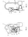
In
Bei einer Bewegung des Hubwerks
Nach den Hubbewegungen werden die Ventile
Ebenso ist ein Ablauf denkbar, bei dem mehrere Hubbewegungen durchgeführt werden, ohne die Druckluft für einen Prozess zu verbrauchen, aber um den Druck in dem Druckluftspeicher
Claims (14)
Translated fromGermanPriority Applications (4)
| Application Number | Priority Date | Filing Date | Title |
|---|---|---|---|
| DE102010019636ADE102010019636A1 (en) | 2010-05-06 | 2010-05-06 | Packaging machine and method with compressed air generation |
| US13/100,698US9446868B2 (en) | 2010-05-06 | 2011-05-04 | Packaging machine and packaging method with generation of pressurized air |
| ES11003666TES2434332T3 (en) | 2010-05-06 | 2011-05-04 | Packaging machine and packaging procedure with compressed air generation |
| EP11003666.2AEP2386492B1 (en) | 2010-05-06 | 2011-05-04 | Packaging machine and method with compressed air generation |
Applications Claiming Priority (1)
| Application Number | Priority Date | Filing Date | Title |
|---|---|---|---|
| DE102010019636ADE102010019636A1 (en) | 2010-05-06 | 2010-05-06 | Packaging machine and method with compressed air generation |
Publications (1)
| Publication Number | Publication Date |
|---|---|
| DE102010019636A1true DE102010019636A1 (en) | 2011-11-10 |
Family
ID=44117109
Family Applications (1)
| Application Number | Title | Priority Date | Filing Date |
|---|---|---|---|
| DE102010019636AWithdrawnDE102010019636A1 (en) | 2010-05-06 | 2010-05-06 | Packaging machine and method with compressed air generation |
Country Status (4)
| Country | Link |
|---|---|
| US (1) | US9446868B2 (en) |
| EP (1) | EP2386492B1 (en) |
| DE (1) | DE102010019636A1 (en) |
| ES (1) | ES2434332T3 (en) |
Cited By (2)
| Publication number | Priority date | Publication date | Assignee | Title |
|---|---|---|---|---|
| CN108528839A (en)* | 2018-04-26 | 2018-09-14 | 佛山市博维环保材料有限公司 | A circulating vacuum structure and packaging machine |
| DE102012018974B4 (en) | 2012-09-26 | 2024-11-14 | Multivac Sepp Haggenmüller Se & Co. Kg | thermoforming packaging machine with stamp forming |
Families Citing this family (2)
| Publication number | Priority date | Publication date | Assignee | Title |
|---|---|---|---|---|
| CN104691801B (en)* | 2015-02-13 | 2017-08-18 | 上海华新医材有限公司 | The production equipment of rubber surgical glove packaging bag |
| CN105905328A (en)* | 2016-05-18 | 2016-08-31 | 杭州中亚机械股份有限公司 | Filling device |
Citations (3)
| Publication number | Priority date | Publication date | Assignee | Title |
|---|---|---|---|---|
| US2724225A (en)* | 1949-11-04 | 1955-11-22 | Ebauches Sa | Packaging machine |
| DE1255294B (en)* | 1964-01-22 | 1967-11-30 | Bellaplast Gmbh | Device for deep drawing of plastic foils |
| DE3111925A1 (en)* | 1981-03-26 | 1982-10-07 | Robert Bosch Gmbh, 7000 Stuttgart | Process and device for saving compressed air, in particular in thermoforming machines |
Family Cites Families (11)
| Publication number | Priority date | Publication date | Assignee | Title |
|---|---|---|---|---|
| US4069645A (en)* | 1974-08-01 | 1978-01-24 | Multivac Sepp Haggenmueller Kg | Vacuum packaging machine for the production of sealed packages |
| US4012888A (en) | 1975-07-31 | 1977-03-22 | Packaging Coordinators, Inc. | Packaging apparatus for forming, filling and sealing receptacles |
| SE511861C2 (en)* | 1998-04-07 | 1999-12-06 | Tetra Laval Holdings & Finance | Method and apparatus for producing a sterile packaging container |
| US7308361B2 (en)* | 2001-10-05 | 2007-12-11 | Enis Ben M | Method of coordinating and stabilizing the delivery of wind generated energy |
| CA2508450A1 (en)* | 2002-12-12 | 2004-06-24 | A.K. Technical Laboratory, Inc. | Elongation drive device of stretch rod in stretch blow molding machine and bottom-type lifting drive device |
| DE10327092A1 (en) | 2003-06-13 | 2004-12-30 | Cfs Germany Gmbh | Work station and packaging machine |
| US7824599B2 (en)* | 2004-07-15 | 2010-11-02 | Azzar James D | System for forming portioned food and a method for the same |
| DE102005038357A1 (en)* | 2005-08-11 | 2007-02-15 | Multivac Sepp Haggenmüller Gmbh & Co. Kg | Packaging machine with at least one pneumatic drive |
| JP2009536133A (en)* | 2006-05-05 | 2009-10-08 | ムルティファク ゼップ ハクゲンミュラー ゲーエムベーハー ウント コー カーゲー | Packing machine, specifically a packing machine including a deep drawing device |
| DE102007031527B3 (en)* | 2007-07-06 | 2008-06-19 | Multivac Sepp Haggenmüller Gmbh & Co. Kg | Packing machine for producing packages from a film comprises working stations in which the pressure and/or the volume stream is controlled using a proportional controller |
| US20090289397A1 (en)* | 2008-05-21 | 2009-11-26 | Pia-K Enterprises, Llc | Forming Station of Apparatus for Making Packaging |
- 2010
- 2010-05-06DEDE102010019636Apatent/DE102010019636A1/ennot_activeWithdrawn
- 2011
- 2011-05-04USUS13/100,698patent/US9446868B2/ennot_activeExpired - Fee Related
- 2011-05-04ESES11003666Tpatent/ES2434332T3/enactiveActive
- 2011-05-04EPEP11003666.2Apatent/EP2386492B1/ennot_activeNot-in-force
Patent Citations (3)
| Publication number | Priority date | Publication date | Assignee | Title |
|---|---|---|---|---|
| US2724225A (en)* | 1949-11-04 | 1955-11-22 | Ebauches Sa | Packaging machine |
| DE1255294B (en)* | 1964-01-22 | 1967-11-30 | Bellaplast Gmbh | Device for deep drawing of plastic foils |
| DE3111925A1 (en)* | 1981-03-26 | 1982-10-07 | Robert Bosch Gmbh, 7000 Stuttgart | Process and device for saving compressed air, in particular in thermoforming machines |
Cited By (3)
| Publication number | Priority date | Publication date | Assignee | Title |
|---|---|---|---|---|
| DE102012018974B4 (en) | 2012-09-26 | 2024-11-14 | Multivac Sepp Haggenmüller Se & Co. Kg | thermoforming packaging machine with stamp forming |
| CN108528839A (en)* | 2018-04-26 | 2018-09-14 | 佛山市博维环保材料有限公司 | A circulating vacuum structure and packaging machine |
| CN108528839B (en)* | 2018-04-26 | 2023-08-29 | 佛山道斯水溶包装技术有限公司 | A circulating vacuum structure and packaging machine |
Also Published As
| Publication number | Publication date |
|---|---|
| EP2386492B1 (en) | 2013-08-28 |
| US20110296799A1 (en) | 2011-12-08 |
| US9446868B2 (en) | 2016-09-20 |
| EP2386492A1 (en) | 2011-11-16 |
| ES2434332T3 (en) | 2013-12-16 |
Similar Documents
| Publication | Publication Date | Title |
|---|---|---|
| EP2384981B1 (en) | Sealing station for a packaging machine | |
| EP2539125B1 (en) | Method for changing the upper and lower tool of a packaging machine | |
| EP0710605B1 (en) | Method and device for maximising the unit rate of a vacuum packaging machine | |
| EP2769923B1 (en) | Deep draw packaging machine with sealing station and method | |
| EP2746173B1 (en) | Deep draw packaging machine and method | |
| EP2522580B1 (en) | Tool swapping device | |
| EP2896573B1 (en) | Deep draw packaging machine with upper film moulding station and corresponding method | |
| EP2668103B1 (en) | PACKAGING MACHINE and method FOR THE PREPARATION OF INDIVIDUAL EVACUATED PACKaGES | |
| EP2447171B1 (en) | Deep draw packaging machine and method for operating the same | |
| EP2386492B1 (en) | Packaging machine and method with compressed air generation | |
| EP2644516A1 (en) | Packaging machine with a sealing device | |
| EP3617076A1 (en) | Packaging machine with suction plate | |
| EP2985234B1 (en) | Deep draw packaging machine with movable mould insert | |
| EP3109018A1 (en) | Deep draw packaging machine with full cutting station and corresponding method | |
| EP3009363A1 (en) | Packaging machine with a cutting station | |
| EP3088315B2 (en) | Deep draw packaging machine with strip puncher | |
| EP2995441B1 (en) | Deep draw packaging machine with lifting device and method | |
| EP3009355A1 (en) | Method for manufacturing a packaging | |
| WO2015169830A1 (en) | Packaging machine with vacuum control module consisting of uniform valve blocks | |
| EP3319881A1 (en) | Packaging machine having residual strip disposal | |
| DE202004016538U1 (en) | Sealing station for packing machines has upper and lower sections which can be moved together to seal articles between sheets, cassette being mounted in upper section containing heated plate which can be raised and lowered | |
| DE102022118988A1 (en) | Separation unit | |
| CN218184386U (en) | Bottle is planted domestic fungus culture medium bottle filling machine | |
| EP3390232A1 (en) | Packaging machine and method for producing evacuated packagings | |
| EP4522389A1 (en) | Separating unit |
Legal Events
| Date | Code | Title | Description |
|---|---|---|---|
| R016 | Response to examination communication | ||
| R119 | Application deemed withdrawn, or ip right lapsed, due to non-payment of renewal fee |