DE102010018977A1 - Wing with retractable wing tail - Google Patents
Wing with retractable wing tailDownload PDFInfo
- Publication number
- DE102010018977A1 DE102010018977A1DE102010018977ADE102010018977ADE102010018977A1DE 102010018977 A1DE102010018977 A1DE 102010018977A1DE 102010018977 ADE102010018977 ADE 102010018977ADE 102010018977 ADE102010018977 ADE 102010018977ADE 102010018977 A1DE102010018977 A1DE 102010018977A1
- Authority
- DE
- Germany
- Prior art keywords
- wing
- lever
- tail
- devices
- main wing
- Prior art date
- Legal status (The legal status is an assumption and is not a legal conclusion. Google has not performed a legal analysis and makes no representation as to the accuracy of the status listed.)
- Ceased
Links
- 230000033001locomotionEffects0.000claimsabstractdescription78
- 238000013519translationMethods0.000claimsabstractdescription13
- 210000001331noseAnatomy0.000claimsdescription63
- 238000000034methodMethods0.000claimsdescription12
- 230000008569processEffects0.000claimsdescription12
- 230000008878couplingEffects0.000claimsdescription11
- 238000010168coupling processMethods0.000claimsdescription11
- 238000005859coupling reactionMethods0.000claimsdescription11
- 238000005452bendingMethods0.000claimsdescription10
- 230000007246mechanismEffects0.000abstractdescription9
- 230000000875corresponding effectEffects0.000description9
- 230000008901benefitEffects0.000description6
- 230000005540biological transmissionEffects0.000description6
- 238000013461designMethods0.000description6
- 238000003780insertionMethods0.000description6
- 230000037431insertionEffects0.000description6
- 239000000463materialSubstances0.000description4
- 230000009471actionEffects0.000description2
- 238000011161developmentMethods0.000description2
- 230000000694effectsEffects0.000description2
- 230000005484gravityEffects0.000description2
- 230000002093peripheral effectEffects0.000description2
- 238000003860storageMethods0.000description2
- 238000012549trainingMethods0.000description2
- 230000001133accelerationEffects0.000description1
- 230000001154acute effectEffects0.000description1
- 238000000418atomic force spectrumMethods0.000description1
- 230000015572biosynthetic processEffects0.000description1
- 239000000969carrierSubstances0.000description1
- 238000010276constructionMethods0.000description1
- 230000002596correlated effectEffects0.000description1
- 238000009826distributionMethods0.000description1
- 238000005265energy consumptionMethods0.000description1
- 230000002349favourable effectEffects0.000description1
- 210000003128headAnatomy0.000description1
- 230000002045lasting effectEffects0.000description1
- 238000004519manufacturing processMethods0.000description1
- 238000005192partitionMethods0.000description1
- 229920003023plasticPolymers0.000description1
- 239000004033plasticSubstances0.000description1
- 230000006641stabilisationEffects0.000description1
- 238000011105stabilizationMethods0.000description1
Images


Classifications
- B—PERFORMING OPERATIONS; TRANSPORTING
- B64—AIRCRAFT; AVIATION; COSMONAUTICS
- B64C—AEROPLANES; HELICOPTERS
- B64C3/00—Wings
- B64C3/38—Adjustment of complete wings or parts thereof
- B64C3/56—Folding or collapsing to reduce overall dimensions of aircraft
Landscapes
- Engineering & Computer Science (AREA)
- Mechanical Engineering (AREA)
- Aviation & Aerospace Engineering (AREA)
- Toys (AREA)
- Transmission Devices (AREA)
Abstract
Translated fromGermanDescription
Translated fromGermanDie Erfindung betrifft einen Flügel mit einer Erstreckung in Spannweitenrichtung, in Flügeltiefenrichtung und in Flügeldickenrichtung insbesondere zur Verwendung für ein Flugzeug mit einklappbarem Flügelendstück. Dabei kommt eine Hebelmechanik zum Einsatz, welche eine Schwenkbewegung eines Flügelendstücks durchführen kann, die sowohl eine Rotationskomponente, als auch eine Translationskomponente aufweist.The invention relates to a wing with an extension in the spanwise direction, in wing depth direction and in the wing thickness direction, in particular for use with an aircraft with a foldable wing tail. In this case, a lever mechanism is used, which can perform a pivotal movement of a wing tail, which has both a rotational component, as well as a translation component.
Derartige Flügel mit einklappbaren Flügelendstücken sind bekannt und werden beispielsweise für Flügel von Flugzeugen eingesetzt, welche auf Flugzeugträgern transportiert werden. Um während des Parkens der Flugzeuge, der so genannten Hangarierung, möglichst geringen Platzbedarf der Flugzeuge zu gewährleisten, werden die Flügelenden hochgeklappt und reduzieren damit die Erstreckung des Flugzeuges in dessen Spannweitenrichtung. Dabei weisen die bekannten Systeme einfache Klappmechanismen auf, welche zum Beispiel über Scharniere um eine einzige Rotationsachse das Flügelendstück relativ zum Hauptflügel in einer Klappbewegung nach oben klappen, also einklappen können. Für den Einsatz des Flugzeuges im Flugbetrieb wird das Flügelendstück entlang dieser einzigen Rotationsachse über das Scharnier mittels der Klappbewegung ausgeklappt und in seine Flugposition gebracht. Beide Klappvorgänge werden üblicherweise manuell oder mit mechanischen Hilfsmitteln durch das Bodenpersonal durchgeführt und üblicherweise von einem Verriegelungsvorgang nach dem Ausklappen der Flügelendstücke gefolgt. Das Verriegeln ist notwendig, um einen sicheren Flugbetrieb zu gewährleisten, insbesondere ein ungewolltes Einklappen der Flügelendstücke während des Fluges zu verhindern.Such wings with retractable Flügelendstücken are known and are used for example for wings of aircraft, which are transported on aircraft carriers. In order to ensure the smallest possible space requirement of the aircraft during the parking of the aircraft, the so-called hangar, the wing ends are folded up, thereby reducing the extent of the aircraft in the spanwise direction. In this case, the known systems on simple folding mechanisms, which fold, for example, hinges about a single axis of rotation, the wing tail relative to the main wing in a folding movement upwards, so can fold. For the use of the aircraft in flight mode, the wing tail along this single axis of rotation is folded over the hinge by means of the folding movement and brought into its flight position. Both folding operations are usually performed manually or by mechanical means by the ground personnel and are usually followed by a locking action after folding out the wing tails. The locking is necessary to ensure safe flight operation, in particular to prevent accidental folding of the wing tips during the flight.
Nachteilig bei den bekannten Systemen ist gerade die einfache Ausgestaltung des Klappmechanismus, welcher eine händische Durchführung der Klappbewegung notwendig macht. Der Aufwand einen solchen Klappmechanismus automatisiert durchzuführen ist sehr groß, da das Einklappen über einen relativ langen Weg des Flügelendstücks erfolgt. Damit ergeben sich zumindest während des Klappvorganges äußert ungünstige Hebelverhältnisse, deren Überwindung einen großen Kraftaufwand durch einen Aktuator erfordert. Damit müsste einerseits ein aufwendiger und damit teuerer Aktuator und andererseits eine verstärkte Ausführung der Klappkinematik ausgeführt werden. Neben den höheren Herstellungskosten führt dies zu höherem Gewicht der Bauteile und damit zu geringerer Wirtschaftlichkeit des Betriebes des Flugzeuges.A disadvantage of the known systems is just the simple design of the folding mechanism, which makes a manual implementation of the folding movement necessary. The effort to perform such a folding mechanism automated is very large, since the folding is done over a relatively long way the wing tail. This results in at least during the folding process extremely unfavorable leverage, the overcoming requires a large amount of force by an actuator. This would require, on the one hand, a complex and thus expensive actuator and, on the other hand, an increased execution of the folding kinematics. In addition to the higher production costs, this leads to higher weight of the components and thus to lower economic efficiency of the operation of the aircraft.
In besonderen Einsatzsituationen kann es jedoch vorteilhaft oder sogar notwenig sein, dass die Klappbewegung automatisch erfolgt. Insbesondere dass sowohl das Einklappen als auch das Ausklappen des Flügelendstücks automatisch durchgeführt werden kann. Dies ist zum Beispiel dann der Fall, wenn große Flugzeuge insbesondere Flugzeuge mit großen Spannweitendimensionierungen für Lasttransporte oder Interkontinentalverbindungen, auf relativ kleinen Flughäfen landen sollen. Ein Landen ist zwar, in Abhängigkeit der Länge der Landebahn, auch für große Flugzeuge auf relativ kleinen Flughäfen möglich, jedoch sind kleine Flughäfen häufig hinsichtlich der maximalen Spannweite der darauf rangierenden Flugzeuge begrenzt. Dabei sind neben den Breiten und der Dichte Rollwege auf dem Rollfeld auch die Parkpositionen, insbesondere an den sogenannten Fingern eines Flughafengebäudes zu berücksichtigen. Die Verwendung von klappbaren Flügelendstücken wäre somit grundsätzlich hilfreich, jedoch nur in einer Ausführungsform, welche gewährleistet, dass das Flugzeug direkt beim Verlassen der Landebahn nach dem landen, bzw. erst nach dem Erreichen der Startbahn kurz vor dem Start, die Flügelendstücke ausklappt werden und damit erst auf der Start- bzw. Landebahn die volle Spannweite hergestellt wird.In special situations, however, it may be advantageous or even necessary that the folding movement takes place automatically. In particular, both the folding and the unfolding of the wing tail can be performed automatically. This is the case, for example, when large aircraft, in particular aircraft with large span dimensions for freight transport or intercontinental connections, are to land at relatively small airports. Landing, although depending on the length of the runway, is also possible for large aircraft at relatively small airports, however, small airports are often limited in the maximum span of aircraft taxiing thereon. In addition to the widths and the density of taxiways on the runway, the parking positions, in particular on the so-called fingers of an airport building, must be taken into account. The use of hinged wing tails would thus be helpful in principle, but only in one embodiment, which ensures that the aircraft landing directly after leaving the runway, or only after reaching the runway shortly before takeoff, the wing tails are folded out and thus only on the runway the full span is produced.
Aufgabe der vorliegenden Erfindung ist es, die voran stehenden beschriebenen Probleme bekannter Systeme zu lösen. Insbesondere ist es Aufgabe der vorliegenden Erfindung, ein klappbares Flügelendstück, insbesondere eine Kinematik hierfür vorzusehen, mit welcher die Möglichkeit besteht ein Flügelendstück eines Flügels automatisch zu schwenken und dabei eine für den Einzelfall sichere Lagerung und einen sicheren Kräfteverlauf über die Schwenkbewegung hinweg erlaubt.The object of the present invention is to solve the above described problems of known systems. In particular, it is an object of the present invention to provide a hinged wing tail, in particular a kinematics for this, with which the possibility exists to pivot a wing end of a wing automatically while a safe for the individual case storage and a safe flow of forces over the pivoting movement away allows.
Voranstehende Aufgabe wird gelöst durch einen Flügel, aufweisend die Merkmale des unabhängigen Anspruchs 1. Bevorzugte Ausführungsformen ergeben sich aus den daran anschließenden Unteransprüchen.The above object is achieved by a wing, comprising the features of independent claim 1. Preferred embodiments will become apparent from the appended subclaims.
Dabei erstreckt sich ein erfindungsgemäßer Flügel in Spannweitenrichtung, in Flügeltiefenrichtung und in Flügeldickenrichtung und ist vorteilhafter Weise für ein Flugzeug zu verwenden. Der erfindungsgemäße Flügel kann ein generell ein aerodynamischer Körper an einem Flugzeug oder einem Fahrzeug sein. Der erfindungsgemäße Flügel kann insbesondere einen Hauptflügel mit einer tragenden Hauptflügelstruktur zur Versteifung des Hauptflügels sowie ein Flügelendstück aufweisen, das als vom Hauptflügel separat ausgeführtes Bauteil mit einer tragenden Flügelendstückstruktur zum Versteifen des Flügelendstücks realisiert ist. Die Hauptflügelstruktur und die Flügelendstückstruktur sind dabei durch Bauteile ausgeführt, wie sie beispielsweise als Hauptflügelbox oder Flügelendstückbox bezeichnet werden.In this case, a wing according to the invention extends in the spanwise direction, in the wing depth direction and in the wing thickness direction and is advantageously to be used for an aircraft. The wing according to the invention may generally be an aerodynamic body on an aircraft or a vehicle. In particular, the wing according to the invention may comprise a main wing having a main wing supporting structure for stiffening the main wing and a wing end realized as a member separate from the main wing and having a wing-end supporting structure for stiffening the wing tail. The main wing structure and the Flügelendstückstruktur are executed by components, as they are referred to, for example, as a main wing box or Flügelendstückbox.
Weiter ist eine Hebelkinematik zur Ausführung einer Schwenkbewegung des Flügelendstücks relativ zum Hauptflügel zwischen einem ausgeklappten und einem eingeklappten Zustand des Flügelendstücks vorgesehen. Diese Hebelkinematik weist zwei Hebelvorrichtungen auf, die jeweils in einer ersten Gelenkvorrichtung in der Hauptflügelstruktur und jeweils in einer zweiten Gelenkvorrichtung in der Flügelendstückstruktur gelagert sind. Es sind also pro Hebelvorrichtung zwei Gelenkvorrichtungen vorgesehen. Dabei sind die Gelenkvorrichtungen derart ausgestaltet, dass die Gelenkvorrichtungen zur Kopplung der Hebelvorrichtung mit der Flügelendstückstruktur in Spannweitenrichtung des Flügelendstücks versetzt angeordnet sind und die Gelenkvorrichtungen zur Kopplung der Hebelvorrichtung mit der Hauptflügelstruktur in Spannweitenrichtung des Hauptflügels versetzt angeordnet sind. Weiter ist zumindest eine der ersten und/oder zweiten Gelenkvorrichtungen derart ausgestaltet, dass die Bewegungsfreiheit der darin gelagerten Hebelvorrichtung auf einen Rotationsfreiheitsgrad begrenzt wird, so dass die Hebelkinematik einen Schwenkvorgang des Flügelendstücks gegenüber dem Hauptflügel mit einem Rotations- und einem Translationsanteil definiert. Further, a lever kinematics for carrying out a pivoting movement of the wing tail relative to the main wing between a deployed and a folded state of the wing tail is provided. This lever kinematics has two lever devices which are each mounted in a first hinge device in the main wing structure and each in a second hinge device in the wing tail structure. So there are two articulated devices per lever device provided. In this case, the hinge devices are designed such that the hinge devices for coupling the lever device with the wing tail structure in the spanwise direction of the wing tail are arranged offset and the hinge devices for coupling the lever device with the main wing structure are arranged offset in the spanwise direction of the main wing. Further, at least one of the first and / or second hinge devices is configured such that the freedom of movement of the lever device mounted therein is limited to a rotational degree of freedom, so that the lever kinematics defines a pivoting operation of the wing tail relative to the main wing with a rotational and a translation portion.
Mit anderen Worten weist die Hebelkinematik eine Viergelenkkinematik auf, wobei jeweils zwei Gelenkvorrichtungen an der Hauptflügelstruktur und zwei Gelenkvorrichtungen an der Flügelendstückstruktur vorgesehen sind. Dabei definiert jede der Gelenkvorrichtungen eine gelenkige Verbindung zwischen der jeweiligen Hebelvorrichtung und der jeweiligen Struktur, also der Hauptflügelstruktur oder der Flügelendstückstruktur. Auf diese Weise sind Hauptflügelstruktur und Flügelendstückstruktur miteinander über die Hebelkinematik, also im weiteren Sinne über die Gelenkvorrichtungen und die Hebelvorrichtungen miteinander gekoppelt.In other words, the lever kinematics on a four-bar linkage, wherein in each case two hinge devices are provided on the main wing structure and two hinge devices on the Flügelendstückstruktur. In this case, each of the joint devices defines an articulated connection between the respective lever device and the respective structure, ie the main wing structure or the wing tail structure. In this way, main wing structure and wing tail structure are coupled to each other via the lever kinematics, so in the broader sense via the hinge devices and the lever devices.
In einem möglichen Fall stellt die Hebelkinematik die einzige Verbindung zwischen Hauptflügelstruktur und Flügelendstückstruktur dar. Mit anderen Worten werden in einem solchen Fall von der Hebelkinematik sämtliche Lasten, die durch Gewicht und Beschleunigungen während des Schwenkvorganges zwischen Flügelendstückstruktur und Hauptflügelstruktur wirken, übertragen. Durch das erfindungsgemäße Vorsehen von zwei Hebelvorrichtungen mit jeweils zwei zur Kopplung geeigneten Gelenkvorrichtungen entsteht die erfindungsgemäße Viergelenkkinematik. Durch die Reduktion der Bewegungsfreiheit des Flügelendstücks durch wenigstens eine der Gelenkvorrichtungen auf einen einzigen Rotationsfreiheitsgrad ist die Relativbewegung, also die Schwenkbewegung, zwischen Flügelendstück und Hauptflügel auf eine einzige Rotationsmöglichkeit beschränkt.In one possible case, the lever kinematics is the only connection between the main wing structure and wing tail structure. In other words, in such a case, all loads acting on the wing tail structure and main wing structure by weight and accelerations during the pivoting operation are transmitted by the lever kinematics. The inventive provision of two lever devices, each with two suitable for coupling joint devices, the four-joint kinematics invention. By reducing the freedom of movement of the Flügelendstücks by at least one of the hinge devices to a single rotational degree of freedom, the relative movement, so the pivotal movement between Flügelendstück and main wing is limited to a single rotation possibility.
Im Vergleich zu den bekannten einfachen Klappmechanismen definiert die erfindungsgemäße Anordnung der Gelenkvorrichtung in jeweils beabstandeten Positionen bezogen auf die jeweilige Spannweitenrichtung, eine komplexe Schwenkbewegung im Vergleich zu den bekannten einfachen Klappbewegungen. Insbesondere bilden die jeweiligen Gelenkvorrichtungen in der Hauptflügelstruktur voneinander in Spannweitenrichtung des Hauptflügels beabstandete Rotationsachsen und die jeweiligen Gelenkvorrichtungen in der Flügelendstückstruktur in Spannweitenrichtung des Flügelendstücks beabstandete Rotationsachsen. Insgesamt sind somit vier Rotationsachsen durch die vier Gelenkvorrichtungen definiert, die durch ihr erfindungsgemäßes Zusammenwirken, welches durch die Kopplung über die Hebelvorrichtungen erzielt wird, in einer Schwenkbewegung des Flügelendstücks resultieren, die nicht ausschließlich aus einer Rotationskomponente besteht, sondern zusätzlich eine Translationskomponente aufweist. Somit kann eine komplexe Schwenkbewegung mit einem Rotationsanteil und einem Translationsanteil durchgeführt werden, welche je nach Einsatzsituation eine ideale Kraftverteilung in der Hebelkinematik ermöglicht. Durch die Variation der exakten Anordnung der einzelnen Gelenkvorrichtungen unter Beachtung der erfindungsgemäßen Vorgaben können die Schwenkbewegung und damit die Hebel-, bzw. die Kraftverhältnisse während des Schwenkvorganges variiert werden.In comparison to the known simple folding mechanisms, the arrangement according to the invention of the articulated device defines in each case spaced positions relative to the respective spanwise direction, a complex pivotal movement in comparison to the known simple folding movements. In particular, the respective hinge devices in the main wing structure form rotational axes spaced from each other in the spanwise direction of the main wing, and the respective hinge devices in the wing tail structure span spaced apart rotational axes in the spanwise direction of the wing tail. Overall, thus four axes of rotation are defined by the four joint devices, which result by their inventive cooperation, which is achieved by the coupling via the lever devices, in a pivotal movement of the wing tail, which does not consist exclusively of a rotational component, but additionally has a translation component. Thus, a complex pivoting movement can be carried out with a rotation component and a translation component which, depending on the application situation, enables an ideal distribution of force in the lever kinematics. By varying the exact arrangement of the individual joint devices in compliance with the specifications of the invention, the pivoting movement and thus the lever, and the force ratios can be varied during the pivoting operation.
Durch das auf diese Weise ermöglichte Einstellen komplexer Schwenkbewegungen sind auch komplexe Belastungssituationen über den Verlauf der Schwenkbewegung einstellbar. Das bedeutet, dass je nach Hebelverhältnis in der jeweiligen Schwenkposition im Verlauf des Schwenkvorgangs unterschiedliche Belastungssituationen in den Hebelvorrichtungen wie auch in den Gelenkvorrichtungen vorherrschen. Diese können durch eine komplexe Schwenkbewegung derart verändert werden, dass sowohl die Gelenkvorrichtungen als auch die Hebelvorrichtungen hinsichtlich ihrer mechanischen Stabilität weniger stark beansprucht werden, also der Maximalwert, welcher während der Schwenkbewegung temporär erreicht wird, reduziert wird. Für die Gesamtkonstruktion des Flügels bedeutet dies, dass sowohl die Hebelvorrichtungen, als auch die Gelenkvorrichtungen einfacher, insbesondere leichter ausgestaltet werden können. Darüber hinaus resultiert die geringere mechanische Belastung über den Schwenkvorgang in einer längeren Dauerstabilität und damit in einer erhöhten Einsatzsicherheit eines erfindungsgemäßen Flügels.By thus enabling complex pivoting movements even complex load situations over the course of the pivoting movement can be adjusted. This means that depending on the lever ratio in the respective pivot position in the course of the pivoting process different load situations in the lever devices as well as in the hinge devices prevail. These can be changed by a complex pivoting movement such that both the joint devices and the lever devices are less stressed in terms of their mechanical stability, so the maximum value which is temporarily achieved during the pivoting movement, is reduced. For the overall construction of the wing, this means that both the lever devices and the hinge devices can be made simpler, in particular lighter. In addition, the lower mechanical load on the pivoting results in a longer lasting stability and thus in an increased operational safety of a wing according to the invention.
Aufgrund der Tatsache, dass eine komplexe Schwenkbewegung durchgeführt werden kann, ist ein erfindungsgemäßer Flügel auch dafür geeignet, mit einer automatischen Aktuierung der Hebelkinematik ausgestattet zu werden. Während bei einfachen Klappbewegungen bekannter Systeme ein nicht beeinflussbarer Belastungsverlauf über die Klappbewegung in einem Scharnier besteht, kann ein erfindungsgemäßer Flügel dahingehend ausgelegt werden, dass die Hebelkinematik über einen komplexen Schwenkbewegungsverlauf einen an die jeweilige Aktuierungsform angepassten komplexen Belastungsverlauf, insbesondere einen komplexen Kraftverlauf über die Schwenkbewegung aufweist und damit eine automatische Durchführung der Schwenkbewegung in wirtschaftlicher Weise erst ermöglicht wird. Es ist also zu unterscheiden zwischen einer erfindungsgemäßen Schwenkbewegung und bekannten Klappbewegungen in einfacher Form über Scharniere wie bei bekannten Systemen.Due to the fact that a complex pivoting movement can be performed, a wing according to the invention is also suitable for being equipped with an automatic actuation of the lever kinematics. While in simple folding movements of known systems a non-influenceable load profile on the Folding movement in a hinge, a wing according to the invention can be interpreted to the effect that the lever kinematics over a complex pivoting movement has adapted to the respective Aktuierungsform complex load history, in particular a complex force curve on the pivotal movement and thus enables an automatic implementation of the pivotal movement in an economical manner becomes. It is therefore to distinguish between a pivoting movement according to the invention and known folding movements in a simple form via hinges as in known systems.
Die beiden Extremsituationen des erfindungsgemäßen Schwenkvorgangs sind der ausgeklappte Zustand des Flügelendstücks sowie der eingeklappte Zustand des Flügelendstücks. Dabei ist unter „ausgeklappter Zustand” des Flügelendstücks zu verstehen, dass sich das Flügelendstück relativ zum Hauptflügel in einer Position befindet, in der es für die Verwendung des Flügels in einer Flugsituation geeignet ist.The two extreme situations of the pivoting process according to the invention are the unfolded state of the wing tail and the folded state of the wing tail. It is to be understood by "folded out" of the wing tail that the wing tail is relative to the main wing in a position in which it is suitable for use of the wing in a flight situation.
Unter der Bezeichnung „eingeklappte Position” des Flügelendstücks ist dabei zu verstehen, dass die maximale Spannweite des Flügels auf ein Minimum, nämlich im Wesentlichen auf die Spannweitenerstreckung des Hauptflügels reduziert ist. Dabei kann eingeklappter Zustand je nach Einsatzsituation unterschiedlich weit eingeklappt bedeuten. So kann je nach Bedarf, also je nach maximaler Spannweitenzulassung eines Flughafens die eingeklappte Position zwischen einem leichten Anheben der Flügelendstücke relativ zum Hauptflügel einerseits und andererseits einem vollständigen Aufstellen, also im Wesentlichen einer senkrechten Anordnung der Flügelendstücke zum Hauptflügel, liegen.The term "folded position" of the wing tail is to be understood that the maximum span of the wing is reduced to a minimum, namely substantially to the span extension of the main wing. In this case, depending on the application situation, the folded-in state can mean that it has been folded in different heights. Thus, depending on the need, so depending on the maximum range approval of an airport, the folded position between a slight lifting of the Flügelendstücke relative to the main wing on the one hand and on the other hand a complete set up, so essentially a vertical arrangement of Flügelendstücke to the main wing.
Ein erfindungsgemäßer Flügel kann dahingehend weitergebildet sein, dass wenigstens eine der Gelenkvorrichtungen derart gestaltet ist, dass darin Biegemomente aufgenommen werden können, deren Momentvektor quer zur Längsrichtung der jeweiligen Hebelvorrichtung und quer zur Rotationsachse der jeweiligen Hebelvorrichtung verläuft. Mit anderen Worten bildet eine solche Gelenkvorrichtung eine Stabilisierung der Flügelendstückstruktur relativ zur Hauptflügelstruktur. Insbesondere wird die Gelenkvorrichtung mit einer solchen Ausgestaltungsform damit eine Torsionsfestigkeit und eine Biegesteifigkeit des Flügelendstücks im Bezug auf den Hauptflügel erreichen. Das bedeutet, dass das Flügelendstück sich relativ zum Hauptflügel aufgrund der erfindungsgemäßen Ausgestaltung zumindest einer der Gelenkvorrichtungen nur in einem einzigen Rotationsfreiheitsgrand bewegen kann. Darüber hinaus sichert wenigstens eine Gelenkvorrichtung auch Torsions- oder Biegemomente, welche auf das Flügelendstück wirken und dieses aus diesem einen Rotationsfreiheitsgrad heraus tordieren bzw. heraus biegen möchten, ab. Auf diese Weise wird die Stabilität eines erfindungsgemäßen Flügels weiter erhöht. Dabei ist zu unterscheiden zwischen einem bewussten Freiheitsgrad der Schwenkbewegung des Flügelendstücks relativ zum Hauptflügel, welche durch das Freigeben eines Rotationsfreiheitsgrades in einer Gelenkvorrichtung gegeben ist, und Biegemomenten und Torsionsmomenten, welche eine Relativbewegung zwischen Flügelendstück und Hauptflügel unabhängig von möglichen Rotationsfreiheitsgraden in den Gelenkvorrichtungen erzwingen. Dabei entstehen solche Torsionsmomente und Biegemomente üblicherweise nicht nur während des Flugbetriebs, also während des ausgeklappten Zustandes des Flügelendstücks, sondern vor allem auch während des Schwenkvorganges selbst. Da der Schwenkvorgang in einfachster Weise nur durch die Hebelkinematik als Kraftpfad zwischen Flügelendstück und Hauptflügel, durchgeführt wird, ist die Schwenkbewegung hinsichtlich Biegemomente und Torsionsmomenten die anfälligste Situation. Die erfindungsgemäße Weiterbildung wenigstens einer der Gelenkvorrichtungen stabilisiert somit das Flügelendstück während der Schwenkbewegung und macht eine Automatisierung des Schwenkvorgangs noch einfacher.A wing according to the invention can be further developed in that at least one of the hinge devices is designed such that bending moments can be absorbed therein whose torque vector extends transversely to the longitudinal direction of the respective lever device and transversely to the axis of rotation of the respective lever device. In other words, such a hinge device stabilizes the wing tail structure relative to the main wing structure. In particular, the hinge device with such an embodiment will thus achieve torsional strength and flexural rigidity of the wing tail with respect to the main wing. This means that the wing tail can move relative to the main wing due to the inventive design of at least one of the hinge devices only in a single rotational freedom grandstand. In addition, at least one hinge device also secures torsional or bending moments acting on the wing tail and twisting it out of that rotational freedom. In this way, the stability of a wing according to the invention is further increased. It is to be distinguished between a deliberate degree of freedom of the pivoting movement of the wing tail relative to the main wing, which is given by the release of a rotational degree of freedom in a hinge device, and bending moments and torsional moments, which force a relative movement between the wing tail and main wing regardless of possible rotational degrees of freedom in the hinge devices. In this case, such torsional moments and bending moments usually arise not only during flight operation, ie during the unfolded state of the wing tail, but especially during the pivoting process itself. Since the pivoting operation is carried out in the simplest manner only by the lever kinematics as a force path between wing tail and main wing, is the pivotal movement with respect to bending moments and torsional moments the most vulnerable situation. The development of at least one of the joint devices according to the invention thus stabilizes the wing tail during the pivoting movement and makes automation of the pivoting process even easier.
Die Ausgestaltung wenigstens einer der Gelenkvorrichtungen der Gestalt, dass derartige Biegemomente oder Torsionsmomente aufgenommen werden können, kann im Wesentlichen durch zwei Grundideen dargestellt werden. Zum einen ist es möglich, dass es sich bei der Gelenkvorrichtung um ein Rotationslager handelt, welches entlang der Rotationsachse eine relativ lange axiale Erstreckung aufweist. Insbesondere sind dabei Rotationslager zu verwenden, welche eine axiale Erstreckung von einem Vielfachen, insbesondere mehr als dem Vierfachen ihrer radialen Erstreckung aufweisen. Auf diese Weise können Biegemomente, wie sie voranstehend beschrieben worden sind, abgestützt werden. Alternativ oder zusätzlich dazu kann eine Gelenkvorrichtung aus mehr als einem einzelnen Gelenk, zum Beispiel aus zwei oder mehr als Rotationslagern gebildeten Gelenken, ausgestaltet werden. Diese zwei oder mehr Rotationslager sind derart angeordnet, dass sie zusammen eine gemeinsame Rotationsachse bilden und aufgrund einer voneinander beabstandeten Anordnung Biegemomente einer Hebelvorrichtung von dem einen Rotationslager gegen das andere abgestützt werden können. Bei einer solchen Ausführungsform ist entscheidend, dass die Hebelvorrichtung mit beiden Rotationslagern der Gelenkvorrichtung festverbunden ist, also in erfindungsgemäßer Weise eine Kopplung über die Hebelvorrichtung vorliegt. Dabei kann in einem solchen Fall die Hebevorrichtung zum Beispiel als H-Lenker ausgeführt sein, so dass die erfindungsgemäße Hebelvorrichtung in zwei voneinander beabstandete Hebel auseinander fällt, welche über einen zentralen Verbindungssteg fest miteinander verbunden sind.The design of at least one of the articulated devices of the form such that such bending moments or torsional moments can be accommodated can essentially be represented by two basic ideas. On the one hand, it is possible for the articulated device to be a rotary bearing which has a relatively long axial extent along the axis of rotation. In particular, rotational bearings are to be used which have an axial extent of a multiple, in particular more than four times their radial extent. In this way, bending moments, as described above, can be supported. Alternatively or additionally, a joint device may be configured from more than a single joint, for example, two or more joints formed as rotational bearings. These two or more rotary bearings are arranged so as to form together a common axis of rotation and, due to a spaced-apart arrangement, bending moments of a lever device can be supported by one rotary bearing against the other. In such an embodiment, it is crucial that the lever device is fixedly connected to both rotation bearings of the articulated device, that is, according to the invention, there is a coupling via the lever device. In this case, in such a case, the lifting device may be designed, for example, as H-handlebar, so that the lever device according to the invention in two spaced-apart lever falls apart, which are firmly connected to each other via a central connecting web.
Weiter kann ein erfindungsgemäßer Flügel in vorteilhafter Weise Abstützmittel aufweisen, welche derart ausgestaltet sind, dass sie im ausgeklappten Zustand des Flügelendstücks einen zur Hebelkinematik zusätzlichen Kraftpfad direkt zwischen Flügelendstückstruktur und Hauptflügelstruktur ausbilden. In einem solchen Fall wird eine zusätzliche Stabilisierung des erfindungsgemäßen Flügels im ausgeklappten Zustand, also im Zustand des Flugbetriebs des Flügels erzielt. Der zweite Kraftpfad erzeugt statisch gesehen eine überbestimmte Lagerung des Flügelendstücks am Hauptflügel, insbesondere der Flügelendstückstruktur an der Hauptflügelstruktur. Es werden somit zwei Kraftpfade vorgesehen, wobei Lasten, welche im Flugbetrieb am Flügelendstück angreifen, sowohl über die Hebelkinematik, als auch über den zweiten Kraftpfad, welcher über die Abstützmittel gebildet wird, abgetragen werden können. Solche Lasten sind zum Beispiel im Flugbetrieb angreifende Luftlasten, welche je nach Flugsituation unterschiedlich groß und in unterschiedliche Richtungen gerichtet sein können.Furthermore, a wing according to the invention can advantageously comprise supporting means, which are configured in such a way that, in the folded-out state of the wing tail, they form a force path additional to the wing kinematics directly between the wing tail structure and the main wing structure. In such a case, an additional stabilization of the wing according to the invention is achieved in the unfolded state, ie in the state of flight operation of the wing. The second force path statically creates an overdetermined bearing of the wing tail on the main wing, in particular the wing tail structure on the main wing structure. There are thus provided two force paths, wherein loads which attack in flight at the wing tail, both on the lever kinematics, as well as on the second power path, which is formed on the support means, can be removed. Such loads are, for example, in flight operations attacking air loads, which may be different in size depending on the flight situation and directed in different directions.
Dabei ist darauf hinzuweisen, dass der zweite Kraftpfad sowohl zu einer teilweisen, als auch zu einer vollständigen Entlastung der Hebelkinematik führen kann. Erfindungsgemäß führt jedoch bereits eine teilweise Entlastung der Hebelkinematik zu einer Möglichkeit, diese Hebelkinematik noch leichter und damit kostengünstiger und im Bezug auf den Energieverbrauch eines Flugzeuges auch wirtschaftlicher zu gestalten. In dem Lastfall im Flugbetrieb, also im ausgeklappten Zustand des Flügelendstücks, wird somit die Hauptlast über die Abstützmittel auf die Hauptflügelstruktur übertragen. Da es sich bei den beiden Kraftpfaden um in mechanischer Sicht parallel angeordnete Kraftpfade handelt, ist es unproblematisch, wenn die Hebelkinematik der schwächere Parallelpfad in diesem parallelen Kraftpfad ist. Mit anderen Worten überbrückt der zweite Kraftpfad der Abstützmittel den ersten Kraftpfad der Hebelkinematik. Je nach konstruktiver Ausgestaltungsform der Abstützmittel ist es jedoch auch möglich, wenn die Hebelkinematik vollständig als Kraftpfad aufgehoben wird und die Abstützmittel den einzigen Kraftpfad darstellen. In einer solchen Weise kann die Hebelkinematik ausschließlich an den angreifenden Lasten während des Schwenkvorgangs ausgelegt werden und zusätzliche Materialstärken und damit Gewicht für den Reiseflugbetrieb des Flügels eingespart werden.It should be noted that the second power path can lead to both a partial, as well as a complete relief of the lever kinematics. According to the invention, however, already a partial relief of the lever kinematics already leads to a possibility to make this lever kinematics even easier and thus more cost-effective and in terms of energy consumption of an aircraft also more economical. In the load case during flight operation, ie in the unfolded state of the wing tail, thus the main load is transmitted via the support means to the main wing structure. Since the two force paths are force paths arranged in parallel in a mechanical view, it is not a problem if the lever kinematics is the weaker parallel path in this parallel force path. In other words, the second force path of the support means bridges the first force path of the lever kinematics. However, depending on the structural design of the support means, it is also possible if the lever kinematics is completely repealed as a force path and the support means represent the only force path. In such a way, the lever kinematics can be designed exclusively for the loads acting during the pivoting process and additional material thicknesses and thus weight for the cruise operation of the wing can be saved.
Erfindungsgemäß können bei einem Flügel die Abstützmittel Nasen sowie den Nasen entsprechende Vertiefungen aufweisen. Die Nasen und die Vertiefungen sind dabei einander korrespondierend derart in der Flügelendstückstruktur und der Hauptflügelstruktur angeordnet, dass die Nasen bei der Durchführung der Schwenkbewegung des Flügelendstücks beim Einklappen aus den Vertiefungen herausgeführt und bei der Durchführung der Schwenkbewegung des Flügelendstücks beim Ausklappen in die Vertiefungen hineingeführt werden. Mit anderen Worten versenken sich die Nasen in den Vertiefungen im ausgeklappten Zustand des Flügelendstücks und sind frei von einander während des Schwenkvorgangs und im eingeklappten Zustand des Flügelendstücks.According to the invention, the supporting means can have noses and depressions corresponding to the noses in the case of a wing. The lugs and the recesses are arranged corresponding to each other in such a manner in the Flügelendstückstruktur and the main wing structure that the lugs are guided in the implementation of the pivoting movement of the Flügelendstücks when folding from the wells and guided in the implementation of the pivoting movement of the Flügelendstücks when unfolding in the wells. In other words, the lobes sink in the recesses in the unfolded state of the wing tail and are free from each other during the pivoting operation and in the folded state of the wing tail.
Auf diese Weise dienen die Nasen durch das Versenken, also das Einführen der Nasen in die Vertiefungen, der mechanischen Abstützung des Flügelendstücks, insbesondere der Flügelendstückstruktur an der Hauptflügelstruktur. Dabei können diese Nasen Radialkräfte in den Vertiefungen übertragen. Die Nasen können dabei im Wesentlichen zylindrisch und/oder konisch geformt sein, jedoch sind auch anderer Querschnittsformen, insbesondere mehreckige Querschnittsformen im Rahmen der vorliegenden Erfindung denkbar. Die Verwendung von konischen Nasen ist insbesondere dann von Vorteil, wenn längere Nasen vorgesehen werden sollen und damit ein Einfädeln der Nasen in die Vertiefung erleichtert werden kann.In this way, the noses serve by sinking, so the introduction of the lugs in the wells, the mechanical support of the wing tail, in particular the Flügelendstückstruktur to the main wing structure. These noses can transmit radial forces in the wells. The lugs may be substantially cylindrical and / or conically shaped, but also other cross-sectional shapes, in particular polygonal cross-sectional shapes in the context of the present invention are conceivable. The use of conical noses is particularly advantageous if longer noses are to be provided and thus threading the noses can be facilitated in the depression.
Die Verwendung einer Korrelation von Nasen, welche am Ende des Schwenkvorganges beim Ausklappen in Vertiefungen einrasten, wird erst durch den Einsatz eines erfindungsgemäßen Flügels, insbesondere der Hebelkinematik möglich. Bei bekannten Systemen, welche reine Klappbewegungen durchführen, handelt es sich bei der Klappbewegung um eine ausschließliche Rotation. Sollen bei der Rotationsbewegung sich rein axial erstreckende Nasen in Vertiefungen hineinbewegen, so ist dies nicht möglich. Es würde zu einem Verklemmen kommen, welches das vollständige Ausklappen des Flügelendstücks verhindert. Erst durch das erfindungsgemäße Ausgestalten der Gelenkvorrichtung und die damit erzielbare Kombination einer Rotationskomponente und einer Translationskomponente bei einem erfindungsgemäßen Schwenkvorgang ist auch ein Einführen von Nasen in Vertiefungen möglich. Dabei ist unerheblich, ob die Nasen in der Flügelendstückstruktur in Vertiefungen der Hauptflügelstruktur einrasten oder umgekehrt. Auch eine Kombination beider Varianten ist möglich.The use of a correlation of lugs which engage in recesses at the end of the pivoting process when unfolding, becomes possible only through the use of a wing according to the invention, in particular the lever kinematics. In known systems which perform mere folding movements, the folding movement is an exclusive rotation. If, during the rotational movement, purely axially extending lugs move into recesses, this is not possible. It would come to a jamming, which prevents the complete unfolding of the wing tail. Only through the inventive design of the joint device and the combination of a rotational component and a translational component which can be achieved with a pivoting process according to the invention is it also possible to introduce noses into depressions. It is irrelevant whether the lugs in the Flügelendstückstruktur engage in recesses of the main wing structure or vice versa. A combination of both variants is possible.
Für den Fall, dass die Nasen einen umlaufenden Kragen aufweisen, welcher sich gegen einen umlaufenden Rand der Vertiefungen abstützt, ist es darüber hinaus möglich, dass neben einer radialen Kraftabstützung auch eine, bezogen auf die Nase axiale Kraftabstützung möglich ist. Auf diese Weise fixieren solche Abstützmittel die Flügelendstückstruktur an der Hauptflügelstruktur in allen bis auf einen Freiheitsgrad. Dieser letzte Freiheitsgrad ist das mögliche Herausbewegen der Nasen aus der Vertiefung. Auch dieser letzte Freiheitsgrad kann noch genommen werden, zum Beispiel durch das Vorsehen von Schnapprastverbindungen oder anderen mechanisch lösbaren, also reversibel erzeugbaren Verbindungen zwischen der Nase und der Vertiefung. In einem solchen Fall würde es also zu dem vollständigen Verriegeln der Flügelendstückstruktur an der Hauptflügelstruktur im ausgeklappten Zustand kommen.In the event that the lugs have a circumferential collar which is supported against a peripheral edge of the recesses, it is also possible that in addition to a radial force support also, relative to the nose axial force support is possible. In this way, such support means fix the wing tail structure to the main wing structure in all but one degree of freedom. This last degree of freedom is the possible moving out of the noses from the Deepening. This last degree of freedom can still be taken, for example by the provision of snap-action connections or other mechanically detachable, ie reversibly producible connections between the nose and the depression. In such a case, it would thus come to the complete locking of the wing tail structure on the main wing structure in the unfolded state.
Die Abstützmittel in Form von Nasen und Vertiefungen ermöglichen also eine Kraftübertragung in wenigstens einer, wenn nicht sogar in mehreren Richtungen. Mittels einfacher Vektorrechnung, also Vektoraddition und Vektorsubtraktion können Restlasten angreifender Luftlasten am Flügelendstück berechnet werden in Abhängigkeit der Ausrichtungen, insbesondere der Achsenrichtung der Nasen und der Vertiefungen und den damit einstellbaren Ausrichtungen der möglichen Kraftübertragungsrichtungen. Die Luftlasten werden auf diese Weise zumindest zum Teil über die Abstützmittel abgetragen. Der nach der Subtraktion des Lastvektors am Flügelendstück und den übertragbaren Kraftkomponenten an den Abstützmitteln verbleibende Restkraftvektor muss über die Hebelkinematik abgetragen werden. Dabei reduziert sich eben dieser Restbetrag der noch abzutragenden Kräfte entscheidend, wodurch die Hebelkinematik einfacher, leichter und damit auch kostengünstiger und wirtschaftlicher ausgeführt werden kann.The support means in the form of noses and depressions thus enable a force transmission in at least one, if not in several directions. By means of a simple vector calculation, ie vector addition and vector subtraction, residual loads of acting air loads on the wing tail can be calculated as a function of the orientations, in particular the axial direction of the lugs and the depressions and the orientations of the possible force transmission directions which can be adjusted with them. The air loads are removed in this way, at least in part on the support means. The remaining after the subtraction of the load vector at the wing tail and the transferable force components remaining on the support means residual force vector must be removed via the lever kinematics. In the process, it is precisely this residual amount of the forces still to be removed which is decisively reduced, making the lever kinematics simpler, easier and therefore more cost-effective and economical.
Weiter kann es vorteilhaft sein, wenn die Abstützmittel korrespondierende Anschläge jeweils an der Hauptflügelstruktur und der Flügelendstückstruktur aufweisen, welche sich im ausgeklappten Zustand des Flügelendstücks gegeneinander abstützen. Selbstverständlich sind solche Anschläge auch zusätzlich vorteilhafter Weise im eingeklappten Zustand vorzusehen, um eine Lagerung unabhängig von der Hebelkinematik der Flügelendstücke im eingeklappten Zustand zu ermöglichen. Solche Anschläge sind im ausgeklappten Zustand eine besonders einfache Ausgestaltungsform der Abstützmittel. Insbesondere bei Situationen, in denen die Schwenkbewegung des Flügelendstücks nicht, wie wohl in den häufigsten Einsatzfällen, nach oben, sondern nach unten durchgeführt wird, kann ein solches Anschlagskonzept für die Abstützmittel in einfacher Weise die Hauptlast, nämlich die Luftlast, welche am Flügel von unten nach oben wirkt und somit direkt mit der Auftriebskraft und damit mit der Gewichtskraft des Flugzeuges korreliert, über die Anschläge der Abstützmittel abgetragen werden.Further, it may be advantageous if the support means have corresponding stops respectively on the main wing structure and the wing tail structure, which are supported against each other in the unfolded state of the wing tail. Of course, such attacks are also additionally advantageous to provide in the folded state to allow storage independent of the kinematics of the wing tail in the folded state. Such attacks are in the unfolded state, a particularly simple embodiment of the support means. In particular, in situations in which the pivoting movement of the wing tail is not carried out, as in the most common cases, upwards, but down, such a stop concept for the support means in a simple way, the main load, namely the air load, which at the wing from below acts upward and thus correlated directly with the buoyancy force and thus with the weight of the aircraft, are removed via the attacks of the support means.
Im Vergleich zu den voran stehenden Abstützmitteln in Form von Nasen und Vertiefungen haben die Anschläge zwar den Nachteil, dass sie im Wesentlichen nur Kraft in einer einziger Kraftrichtung übertragen können, jedoch den großen Vorteil, dass über Anschläge auch großflächige Kontaktmöglichkeiten bestehen und damit große Kräfte über große Flächen mit damit einhergehender geringer Flächenpressung und damit wiederum ein einhergehender geringerer Materialbelastung möglich werden. Dabei sind die Anschläge sowohl als im Wesentlichen ebene Flächen, aber auch als Konturflächen denkbar, welche die Kraftübertragungsmöglichkeiten in mehrere Richtungen erhöhen.Compared to the preceding support means in the form of lugs and depressions, the attacks have the disadvantage that they can transmit substantially only force in a single direction of force, but the great advantage that over attacks also large-area contact opportunities and thus large forces over large areas with concomitant low surface pressure and thus in turn a concomitant lower material load are possible. The stops are conceivable both as substantially flat surfaces, but also as contoured surfaces, which increase the power transmission possibilities in several directions.
Es ist möglich, dass im Rahmen der vorliegenden Erfindung die Hebelkinematik einen ersten Punkt und einen vierten Punkt in der Hauptflügelstruktur aufweist, an welchen Gelenkvorrichtungen in Form von Rotationslagern vorgesehen sind. Weiter weist die Hebelkinematik in einer solchen Ausführungsform einen dritten Punkt und einen fünften Punkt in der Flügelendstückstruktur auf, an welchen ebenfalls Gelenkvorrichtungen in Form von Rotationslagern vorgesehen sind. Dabei erstreckt sich zwischen dem ersten Punkt und dem dritten Punkt die erste Hebelvorrichtung und zwischen dem vierten Punkt und dem fünften Punkt die zweite Hebelvorrichtung, welche jeweils rotatorisch in den jeweiligen Rotationslagern gelagert sind. Es ist darauf hinzuweisen, dass, wie weiter oben bereits beschrieben, sowohl die Hebelvorrichtung, als auch die Gelenkvorrichtungen sich über mehrere Ebenen erstrecken können. So können Gelenkvorrichtungen mehr als ein Rotationslager aufweisen und Hebelvorrichtungen mehr als ein Hebel. Dabei ist jedoch allen Rotationslagern einer Gelenkvorrichtung gemein, dass sie eine gemeinsame Rotationsachse, also allgemein eine gemeinsame Bewegungsmöglichkeit definieren. Den einzelnen Hebeln einer Hebelvorrichtung ist gemein, dass sie aufgrund ihrer Anordnung um gemeinsame Rotationsachsen, welche durch die beiden jeweiligen Gelenkvorrichtungen definiert sind, rotieren können. Dabei ist unerheblich, ob die einzelnen Hebel fest miteinander verbunden sind oder nicht.It is possible that in the context of the present invention, the lever kinematics has a first point and a fourth point in the main wing structure, on which hinge devices are provided in the form of rotation bearings. Further, in such an embodiment, the lever kinematics has a third point and a fifth point in the wing tail structure on which hinge devices in the form of rotation bearings are also provided. In this case, the first lever device extends between the first point and the third point and, between the fourth point and the fifth point, the second lever device, which are each mounted rotatably in the respective rotation bearings. It should be noted that, as already described above, both the lever device, as well as the hinge devices can extend over several levels. Thus, hinge devices may have more than one rotary bearing and lever devices more than one lever. However, all rotary bearings of a joint device have in common that they define a common axis of rotation, that is generally a common possibility of movement. The individual levers of a lever device have in common that they can rotate due to their arrangement about common axes of rotation, which are defined by the two respective hinge devices. It is irrelevant whether the individual levers are firmly connected or not.
Die Schwenkbewegung des Flügelendstücks wird durch eine Überlagerung von vier Rotationsbewegungen erzielt. So rotiert die erste Hebelvorrichtung um die hauptflügelstrukturseitige Gelenkvorrichtung, während die Flügelendstückstruktur wiederum um die entsprechende Gelenkvorrichtung der ersten Hebelvorrichtung rotiert. In gleicher Weise rotiert die zweite Hebelvorrichtung um die hauptflügelstrukturseitige Gelenkvorrichtung während wiederum die Flügelendstückstruktur um die entsprechende Gelenkvorrichtung der zweiten Hebelvorrichtung rotiert. Alle vier Rotationsbewegungen ergeben zusammen eine komplexe Schwenkbewegung der Flügelendstückstruktur gegenüber der Hauptflügelstruktur.The pivotal movement of the wing tail is achieved by a superposition of four rotational movements. Thus, the first lever device rotates about the main wing structure side hinge device, while the wing tail structure rotates again about the corresponding hinge device of the first lever device. In the same way, the second lever device rotates about the main wing structure side hinge device while in turn the wing tail structure rotates about the corresponding hinge device of the second lever device. All four rotational movements together result in a complex pivotal movement of the wing tail structure with respect to the main wing structure.
Weiter kann es vorteilhaft sein, wenn bei einem erfindungsgemäßen Flügel ein Aktuator vorgesehen ist, welcher über die Hebelkinematik die Schwenkbewegung des Flügelendstücks relativ zum Hauptflügel ausführt und in einem sechsten Punkt in der Hauptflügelstruktur, welcher ein Rotationslager aufweist, rotatorisch gelagert ist. Ein solcher Aktuator kann zum Beispiel als Translationsaktuator ausgeführt sein, welcher in bekannter Weise hydraulisch, pneumatisch, elektrisch oder rein mechanisch betätigt wird. Jedoch sind alternativ dazu auch Ausführungsformen denkbar, bei denen der Aktuator ein Rotationsaktuator ist, welcher im einfachsten Fall durch einen Elektromotor gebildet wird. Auch eine Kombination von Rotationsmechanismen und Translationsmechanismen ist für die Aktuierung der Hebelkinematik denkbar.Further, it may be advantageous if an actuator is provided in an inventive wing, which performs the pivoting movement of the Flügelendstücks relative to the main wing via the lever kinematics and at a sixth point in the main wing structure, which is a rotary bearing has rotatably mounted. Such an actuator can be embodied, for example, as a translation actuator, which is actuated hydraulically, pneumatically, electrically or purely mechanically in a known manner. However, as an alternative, embodiments are also conceivable in which the actuator is a rotary actuator, which is formed in the simplest case by an electric motor. A combination of rotational mechanisms and translation mechanisms is conceivable for the actuation of the lever kinematics.
Weiter kann es vorteilhaft sein, wenn der Aktuator an seinem zum sechsten Punkt gegenüber liegenden Ende an einem von dem Viergelenk der Hebelkinematik separaten zweiten Punkt rotatorisch an der Hebelkinematik gelagert ist. Mit anderen Worten weist die Hebelkinematik am zweiten Punkt somit ein weiteres Rotationslager auf, zwischen welchem und dem Rotationslager im sechsten Punkt sich die Aktuierung der Hebelkinematik ereignet. Im Falle eines Translationsaktuators wird der Abstand zwischen dem zweiten und dem sechsten Punkt variiert, wodurch die Schwenkbewegung der Hebelkinematik in die einklappende Richtung oder in die ausklappende Richtung durchgeführt werden kann. Jedoch ist es auch möglich, wenn der zweite Punkt, also der Angriffspunkt des Aktuators an der Hebelkinematik in einer der beiden Gelenkvorrichtungen liegt, welche in der Flügelendstückstruktur angeordnet sind. Jedoch ist auf jeden Fall auszuschließen, dass die Aktuierung in einer der beiden Gelenkvorrichtungen der Hauptflügelstruktur erfolgt. In einem solchen Fall würde keine Variation des Abstandes zwischen dem ersten oder dem vierten Punkt einerseits und dem sechsten Punkt andererseits möglich sein, da all diese drei Punkte ortsfest in der Hauptflügelstruktur sind.Further, it may be advantageous if the actuator is rotatably mounted on the lever kinematics at its end opposite to the sixth point at a separate from the four-bar linkage of the lever kinematics second point. In other words, the lever kinematics at the second point thus another rotation bearing, between which and the rotation bearing in the sixth point, the actuation of the lever kinematics occurs. In the case of a translation actuator, the distance between the second and the sixth point is varied, whereby the pivotal movement of the lever kinematics in the folding direction or in the deploying direction can be performed. However, it is also possible if the second point, that is to say the point of application of the actuator on the lever kinematics, lies in one of the two articulated devices which are arranged in the wing tail structure. However, it can be ruled out in any case that the actuation takes place in one of the two articulated devices of the main wing structure. In such a case, no variation of the distance between the first or the fourth point on the one hand and the sixth point on the other hand would be possible, since all these three points are stationary in the main wing structure.
Es ist der Angriffspunkt der Aktuierung, also der zweite Punkt, derart in der Hebelkinematik zu wählen, dass aufgrund der sich damit einstellenden Hebelverhältnisse einerseits der Aktuierungsweg, also zum Beispiel der Rotationsweg oder der Translationsweg des Aktuators ausreichend klein hinsichtlich der Dimensionierung des Aktuators ist und andererseits die Aktuierungskraft, also die Kraft, welche notwendig ist, den Schwenkvorgang in beide Richtungen durchzuführen, ebenfalls möglichst gering wird. Auch die voranstehende Möglichkeit wird erst durch eine erfindungsgemäße Anordnung der Gelenkvorrichtungen in Form einer Viergelenkkinematik möglich. Erst in einem solchen Fall ist überhaupt eine Variation des Angriffspunktes eines Aktuators möglich und damit eine Variation der Kräfte für die Schwenkbewegung sowie des Aktuatorweges.It is the point of actuation of the actuation, so the second point, to be selected in the lever kinematics, that due to the thus adjusting leverage on the one hand the Aktuierungsweg, so for example the rotation path or the translation of the actuator is sufficiently small in terms of dimensioning of the actuator and on the other the Aktuierungskraft, so the force which is necessary to perform the pivoting operation in both directions, also as low as possible. The above possibility is only possible by an inventive arrangement of the joint devices in the form of a four-joint kinematics. Only in such a case is a variation of the point of application of an actuator possible and thus a variation of the forces for the pivoting movement and the Aktuatorweges.
Auch kann es vorteilhaft sein, wenn bei einem erfindungsgemäßen Flügel die beiden Hebelvorrichtungen in Flügeltiefenrichtung voneinander beabstandet ausgebildet sind. Dabei ist die Flügeltiefenrichtung auf den Gesamtflügel bezogen, also auf einen Flügel, bei welchem sich das Flügelendstück im ausgeklappten Zustand befindet. Die Beabstandung der beiden Hebelvorrichtungen in den Flügeltiefenrichtungen voneinander hat den Vorteil, dass die Hebelkinematik als solche in mehrere Teile zerfallen kann, ohne die Funktionalität der Hebelkinematik aufzuheben. Dies ist insbesondere dann von Vorteil, wenn es sich im Bereich der Flügelendstückstruktur und/oder der Hauptflügelstruktur um beengte Platzverhältnisse handelt. Insbesondere kann auf diese Weise eine Bauform erzielt werden, bei welcher weder die Flügelendstückstruktur noch die Hauptflügelstruktur durchbrochen werden muss. Somit ist es möglich, dass mit einem erfindungsgemäßen Flügel eine hohe Stabilität der Flügelendstückstruktur und der Hauptflügelstruktur beibehalten und durch die Flexibilität der Ausbildungsform der Hebelkinematik trotzdem eine erfindungsgemäße Schwenkbewegung des Flügelendstücks ermöglicht wird. Dabei ist es selbstverständlich auch möglich, dass zumindest eine der Hebelvorrichtungen mehrere voneinander separate Hebel aufweist, welche ebenfalls in Flügeltiefenrichtung voneinander beabstandet sind. Zum Beispiel ist eine Ausführungsform denkbar, bei welcher der zweite Hebel als zentraler H-Lenker innerhalb der Hauptflügelstruktur angeordnet ist und zwei voneinander separate Hebel der ersten Hebelvorrichtung außerhalb der Hauptflügelstruktur auf den beiden einander gegenüber liegenden Seiten der Hauptflügelstruktur angeordnet sind. Ein Durchbrechen der Hauptflügelstruktur ist nicht notwendig, da weder die beiden voneinander separaten Hebel der ersten Hebelvorrichtung miteinander verbunden werden müssen, noch eine Verbindung zwischen der ersten Hebelvorrichtung und der zweiten Hebelvorrichtung notwendig ist.It may also be advantageous if, in a wing according to the invention, the two lever devices are formed spaced apart in wing depth direction. The wing depth direction is based on the overall wing, ie on a wing, in which the wing tail is in the unfolded state. The spacing of the two lever devices in the wing depth directions from one another has the advantage that the lever kinematics as such can disintegrate into several parts without removing the functionality of the lever kinematics. This is particularly advantageous if there is limited space in the area of the wing tail structure and / or the main wing structure. In particular, a design can be achieved in this way, in which neither the wing tail structure nor the main wing structure must be broken. Thus, it is possible that maintain a high stability of the Flügelendstückstruktur and the main wing structure with a wing according to the invention and still allows a pivotal movement of the wing tail according to the invention by the flexibility of the embodiment of the lever kinematics. It is of course also possible that at least one of the lever devices comprises a plurality of separate levers, which are also spaced apart in wing depth direction from each other. For example, an embodiment is conceivable in which the second lever is arranged as a central H-link within the main wing structure and two separate levers of the first lever device are arranged outside the main wing structure on the two mutually opposite sides of the main wing structure. Breaking through of the main wing structure is not necessary since neither the two mutually separate levers of the first lever device must be connected to each other, nor a connection between the first lever device and the second lever device is necessary.
Wie voran stehend bereits beschrieben, kann es vorteilhaft sein, wenn zumindest eine der beiden Hebelvorrichtungen als H-Lenker ausgebildet ist, welcher sich in Flügeltiefenrichtung erstreckt. Die Ausbildung als H-Lenker lässt die entsprechende Hebelvorrichtung in zwei einzelne Hebel zerfallen, welche über einen zentralen Steg miteinander verbunden sind. Auf diese Weise kann die Biegesteifigkeit erzielt werden, wie sie bereits weiter oben erläutert worden ist.As already described above, it may be advantageous if at least one of the two lever devices is designed as an H-link, which extends in wing depth direction. The training as H-handlebars can decay the corresponding lever device into two individual levers, which are interconnected via a central web. In this way, the bending stiffness can be achieved, as has already been explained above.
Ein weiterer Vorteil der vorliegenden Erfindung ist es, wenn bei einem erfindungsgemäßen Flügel die Flügelendstückstruktur in Spannweitenrichtung durch wenigstens einen Fortsatz entlang der Hauptflügelstruktur erweitert wird. An dem Ende des Fortsatzes in Spannweitenrichtung der Flügelendstückstruktur gegenüber der Flügelspitze ist dabei eine der beiden Gelenkvorrichtungen der Hebelkinematik an der Flügelendstückstruktur angeordnet. Der Fortsatz verlängert also die Flügelendstückstruktur und erzeugt damit sozusagen eine Überschneidung der Flügelendstückstruktur mit der Hauptflügelstruktur. Durch diese Überschneidung, welche selbstverständlich auch mehrfach, also in Form von mehr als einem Fortsatz vorgesehen sein kann, wird es möglich, dass die Hebelkinematik noch günstiger hinsichtlich der Kraft- und Wegverhältnisse ausgebildet wird. Dabei wird der Abstand einer der Gelenkvorrichtungen in der Flügelendstückstruktur möglichst weit von dem Schwerpunkt der Flügelendstückstruktur entfernt. Auf diese Weise reduziert sich, aufgrund der sich damit ergebenden Hebelverhältnisse, die Belastung der entsprechenden Gelenkvorrichtung. Einmal mehr zeigt sich an dieser Ausführungsform der Erfindung, dass durch eine erfindungsgemäße Anordnung von Gelenkvorrichtungen und Hebelvorrichtungen eine vorteilhafte Einstellbarkeit der Kraft- und Hebelverhältnisse während des Schwenkvorgangs ermöglicht wird, wie sie durch bekannte Systeme mit einfachen Klappmechanismen nicht möglich wäre.Another advantage of the present invention is that, in a wing according to the invention, the wing tail structure is widened in the spanwise direction by at least one extension along the main wing structure. In this case, one of the two articulated devices of the lever kinematics is arranged on the wing tail structure at the end of the extension in the spanwise direction of the wing tail structure with respect to the wing tip. The extension thus extends the wing tail structure and thus creates an overlap, so to speak the wing tail structure having the main wing structure. By this overlap, which of course can be provided several times, ie in the form of more than one extension, it is possible that the lever kinematics is even more favorable in terms of power and path conditions. The distance of one of the hinge devices in the wing tail structure is removed as far as possible from the center of gravity of the wing tail structure. In this way reduces, due to the resulting leverage, the burden of the corresponding hinge device. Once again shows in this embodiment of the invention that an inventive arrangement of joint devices and lever devices an advantageous adjustability of the power and leverage ratios during the pivoting operation is made possible, as would not be possible by known systems with simple folding mechanisms.
Auch kann es im Rahmen der vorliegenden Erfindung vorteilhaft sein, wenn zumindest eine der beiden Hebelvorrichtungen eines erfindungsgemäßen Flügels in Spannweitenrichtung zwischen dem Fortsatz der Flügelendstückstruktur und der Hauptflügelstruktur angeordnet ist. Ein weiterer Vorteil ist erzielbar, wenn bei einem erfindungsgemäßen Flügel zumindest eine der beiden Hebelvorrichtungen innerhalb der Hauptflügelstruktur angeordnet ist. Die Kombination der beiden voranstehenden Ausführungsformen beinhaltet damit die Anordnung aller Hebelvorrichtungen in Bereichen, welche von einer die jeweilige Hauptflügelstruktur bzw. Flügelendstückstruktur umgebende Flügelkontur nicht verlässt. Damit sind die Hebelvorrichtungen einerseits geschützt anordenbar, andererseits hinsichtlich der Aerodynamik des Flügels in Bereichen vorsehbar, welche die Aerodynamik, also die Außenkontur des Flügels nicht beeinträchtigen.It may also be advantageous in the context of the present invention, if at least one of the two lever devices of a wing according to the invention is arranged in the spanwise direction between the extension of the Flügelendstückstruktur and the main wing structure. A further advantage can be achieved if, in the case of a wing according to the invention, at least one of the two lever devices is arranged within the main wing structure. The combination of the two preceding embodiments thus includes the arrangement of all lever devices in areas which does not leave a wing contour surrounding the respective main wing structure or wing tail structure. Thus, the lever devices are on the one hand protected can be arranged, on the other hand in terms of the aerodynamics of the wing in areas providable that do not affect the aerodynamics, so the outer contour of the wing.
Ein weiterer Vorteil kann dadurch erzielt werden, dass bei einem erfindungsgemäßen Flügel eine Flügelhaut vorgesehen ist, die die Kontur des Hauptflügels definiert. Diese Kontur des Hauptflügels ist vorteilhafter Weise die aerodynamische Kontur, welche als Flügelkontur den Auftrieb während der Vorwärtsbewegung des Flugzeuges im Flug erzeugt. In der Flügelhaut ist wenigstens eine Öffnung vorgesehen, die derart ausgestaltet ist, dass sich Abschnitte der Hebelkinematik und/oder des Flügelendstücks und/oder der Flügelendstücksstruktur während des Schwenkvorgangs des Flügelendstücks sich durch die Öffnung hindurch bewegen können. Es ist somit möglich, dass der Schwenkbereich einzelner Bauteile der Hebelkinematik, des Flügelendstücks oder der Flügelendstückstruktur sich über die Flügelkontur des Hauptflügels hinaus erstreckt.A further advantage can be achieved in that a wing skin is provided in a wing according to the invention, which defines the contour of the main wing. This contour of the main wing is advantageously the aerodynamic contour which, as a wing contour, generates the lift during the forward movement of the aircraft in flight. At least one opening is provided in the wing skin, which is configured such that portions of the lever kinematics and / or the wing tail and / or the wing tail structure can move through the aperture during pivoting of the wing tail. It is thus possible that the pivoting range of individual components of the lever kinematics, the wing tail or wing tail structure extends beyond the wing contour of the main wing.
Vorteilhafter Weise ist dabei für jede Öffnung wenigstens eine Abdeckung vorgesehen, welche im ausgeklappten Zustand des Flügelendstücks die jeweilige Öffnung abdeckt. Durch das Vorsehen der Abdeckungen ist im ausgeklappten Zustand, also im Zustand der Flugsituation die aerodynamische Kontur des Hauptflügels durch das Vorhandensein der Öffnungen nicht gestört. Trotzdem ermöglicht die Öffnung ein freies Schwenken des Flügelendstücks in gewünschter Weise. Somit ist eine erfindungsgemäße Hebelkinematik, insbesondere hinsichtlich komplexer Schwenkvorgänge auch mit aerodynamisch notwendigen oder wirtschaftlich effizienten Flügelgeometrien kombinierbar.Advantageously, at least one cover is provided for each opening, which covers the respective opening in the unfolded state of the wing tail. By providing the covers in the unfolded state, ie in the state of the flight situation, the aerodynamic contour of the main wing is not disturbed by the presence of the openings. Nevertheless, the opening allows free pivoting of the wing tail in the desired manner. Thus, a lever kinematics according to the invention, in particular with regard to complex pivoting operations can also be combined with aerodynamically necessary or economically efficient blade geometries.
Es kann vorteilhaft sein, wenn eine solche Abdeckung ebenfalls automatisiert die Öffnung verschließt. Dies ist zum Beispiel dadurch erzielbar, dass jede Abdeckung elastisch derart mit der Flügelendstückstruktur verbunden ist, dass die Abdeckung im ausgeklappten Zustand des Flügelendstücks gegen die jeweilige Öffnung gedrückt wird. Die elastische Ausbildung kann beispielsweise über elastische Elemente, elastische Kunststoffe oder über Federelemente erzielt werden. Dabei sind vorteilhafter Weise Führungsmittel vorzusehen, welche die Bewegungsfreiheit der Abdeckungen dahingehend begrenzen, dass sie sich ausschließlich in einer Richtung frei bewegen können, und in dieser einen Richtung von der elastischen Anbindung gegen die Öffnung, zum Beispiel gegen Anschläge am Rand der Öffnung gedrückt werden.It may be advantageous if such a cover also automatically closes the opening. This can be achieved, for example, in that each cover is elastically connected to the wing tail structure in such a way that the cover is pressed against the respective opening in the unfolded state of the wing tail. The elastic training can be achieved for example via elastic elements, elastic plastics or spring elements. It is advantageous to provide guide means which limit the freedom of movement of the covers to the effect that they can move freely in one direction only, and are pressed in this one direction of the elastic connection against the opening, for example against stops at the edge of the opening.
Die Erfindung wird weiter beschrieben anhand der Ausführungsbeispiele in den nachfolgenden Figuren. Dabei beziehen sich die Begriffe alle in „links”, „rechts”, „oben” und „unten” auf die Zeichnungsfiguren mit einer Ausrichtung mit normal lesbaren Bezugszeichen. Es zeigen:The invention will be further described with reference to the embodiments in the following figures. The terms all refer to "left", "right", "top" and "bottom" to the drawing figures with an orientation with normal readable reference numerals. Show it:
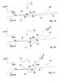
Anhand der
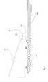
In
Die Punkte P2 und P6 sind im Bezug auf die Erfindung optional, als eine Möglichkeit der Anordnung eines Aktuators
Wird nun der Abstand zwischen den Punkten P2 und P6 verändert, so schiebt der Aktuator
Den Abschluss der Schwenkbewegung bildet die Situation, wie sie in
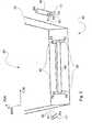
In
Beide Hebel der zweiten Hebelvorrichtung H2 weisen einen Punkt P4 und einen Punkt P5 auf, in welchem jeweils, in der
Die ausführlich zu den
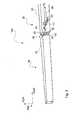
Wie in
In
Auch ist in
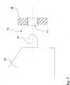
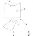
In
Mit einer Strichlinie gezeigt ist die Hauptachse der Nase
Folgt man der Hauptachse der Nase
Darüber hinaus kann es vorteilhaft sein, wenn die Flügelendstückstruktur
In
Im ausgeklappten Zustand des Flügelendstücks
In
In
Diese kann darüber hinaus derart ausgeführt sein, dass sie, wie in
In
BezugszeichenlisteLIST OF REFERENCE NUMBERS
- 2020
- Hauptflügelmain wing
- 2222
- HauptflügelstrukturThe main wing structure
- 4040
- FlügelendstückFlügelendstück
- 4242
- FlügelendstückstrukturFlügelendstückstruktur
- 4444
- Fortsatzextension
- 4646
- Abdeckungcover
- 6060
- Hebelkinematiklever kinematics
- 6262
- Gelenkjoint
- 7070
- Abstützmittelsupport means
- 7272
- Nasenose
- 7474
- Vertiefungdeepening
- 8080
- Aktuatoractuator
- 100100
- Flügelwing
- 102102
- Flügelachsewing axis
- 110110
- Flügelhautwing skin
- 112112
- Öffnungopening
- P1P1
- erster Punktfirst point
- P2P2
- zweiter Punktsecond point
- P3P3
- dritter Punktthird point
- P4P4
- vierter Punktfourth point
- P5P5
- fünfter Punktfifth point
- P6P6
- sechster Punktsixth point
- H1H1
- erster Hebel der Hebelkinematikfirst lever of the lever kinematics
- H2H2
- zweiter Hebel der Hebelkinematiksecond lever of the linkage kinematics
- FTRFTR
- FlügeltiefenrichtungChordwise
- FDRFDR
- FlügeldickenrichtungWing thickness direction
- SWRSWR
- FlügelspannweitenrichtungWingspan direction
- SWR-20SWR-20
- Spannweitenrichtung des HauptflügelsSpanwise direction of the main wing
- SWR-40SWR-40
- Spannweitenrichtung des FlügelendstücksSpan direction of the wing tail
Claims (15)
Translated fromGermanPriority Applications (5)
| Application Number | Priority Date | Filing Date | Title |
|---|---|---|---|
| DE102010018977ADE102010018977A1 (en) | 2010-05-03 | 2010-05-03 | Wing with retractable wing tail |
| EP11721427.0AEP2566754B1 (en) | 2010-05-03 | 2011-05-03 | Wing with retractable wing end piece |
| PCT/EP2011/002212WO2011144298A1 (en) | 2010-05-03 | 2011-05-03 | Wing with retractable wing end piece |
| CN201180034127.XACN102985321B (en) | 2010-05-03 | 2011-05-03 | Wings with retractable wing end pieces |
| US13/667,558US9139285B2 (en) | 2010-05-03 | 2012-11-02 | Wing with retractable wing end piece |
Applications Claiming Priority (1)
| Application Number | Priority Date | Filing Date | Title |
|---|---|---|---|
| DE102010018977ADE102010018977A1 (en) | 2010-05-03 | 2010-05-03 | Wing with retractable wing tail |
Publications (1)
| Publication Number | Publication Date |
|---|---|
| DE102010018977A1true DE102010018977A1 (en) | 2011-11-03 |
Family
ID=44786422
Family Applications (1)
| Application Number | Title | Priority Date | Filing Date |
|---|---|---|---|
| DE102010018977ACeasedDE102010018977A1 (en) | 2010-05-03 | 2010-05-03 | Wing with retractable wing tail |
Country Status (5)
| Country | Link |
|---|---|
| US (1) | US9139285B2 (en) |
| EP (1) | EP2566754B1 (en) |
| CN (1) | CN102985321B (en) |
| DE (1) | DE102010018977A1 (en) |
| WO (1) | WO2011144298A1 (en) |
Cited By (1)
| Publication number | Priority date | Publication date | Assignee | Title |
|---|---|---|---|---|
| WO2015150817A1 (en)* | 2014-04-04 | 2015-10-08 | Airbus Operations Limited | An aircraft wing with a wing tip device and a strut |
Families Citing this family (28)
| Publication number | Priority date | Publication date | Assignee | Title |
|---|---|---|---|---|
| DE102010018977A1 (en) | 2010-05-03 | 2011-11-03 | Airbus Operations Gmbh | Wing with retractable wing tail |
| US9908612B2 (en)* | 2011-10-01 | 2018-03-06 | The Boeing Company | Fold wing tip having stub spar |
| US9783284B2 (en) | 2014-05-20 | 2017-10-10 | The Boeing Company | Rotary drive assembly for wing tip |
| CN104627354B (en)* | 2015-01-16 | 2016-08-24 | 成都西可科技有限公司 | Outdoor aircraft wing folds device |
| GB2535489A (en)* | 2015-02-17 | 2016-08-24 | Airbus Operations Ltd | An arrangement for moving a wing tip device between a flight configuration and a ground configuration |
| GB2535580A (en) | 2015-02-17 | 2016-08-24 | Airbus Operations Ltd | Actuation assembly for moving a wing tip device on an aircraft wing |
| GB2535488A (en)* | 2015-02-17 | 2016-08-24 | Airbus Operations Ltd | An arrangement for effecting movement of a wing tip device between a flight configuration and a ground configuration |
| GB201520289D0 (en)* | 2015-11-18 | 2015-12-30 | Airbus Operations Ltd | An actuation assembly with a track and follower for use in moving a wing tip device on an aircraft wing |
| EP3170742B1 (en) | 2015-11-18 | 2018-02-21 | Airbus Operations GmbH | Foldable wing for an aircraft and aircraft having a foldable wing |
| WO2017136316A1 (en)* | 2016-02-01 | 2017-08-10 | Tudor Crossfelt, Llp | Folding beam for swinging wing |
| EP3246244B1 (en) | 2016-05-20 | 2019-03-20 | Airbus Operations GmbH | A system for locking a foldable wing tip on a wing end of an aircraft |
| GB2547957A (en) | 2016-05-24 | 2017-09-06 | Airbus Operations Ltd | Winglet |
| EP3263446B1 (en) | 2016-06-29 | 2019-06-05 | Goodrich Actuation Systems Limited | Folding wing |
| GB2557978A (en) | 2016-12-21 | 2018-07-04 | Airbus Operations Ltd | Locking device |
| US10370084B2 (en)* | 2017-07-21 | 2019-08-06 | The Boeing Company | Methods and apparatus to adjust folding wing tips |
| GB2573120A (en)* | 2018-04-24 | 2019-10-30 | Airbus Operations Ltd | Improved secondary locking mechanism |
| US11440638B2 (en)* | 2018-05-03 | 2022-09-13 | Airbus Operations Gmbh | Wing for an aircraft |
| CN110525635A (en)* | 2018-05-25 | 2019-12-03 | 空中客车德国运营有限责任公司 | Wing and aircraft for aircraft |
| US11370526B2 (en)* | 2018-05-31 | 2022-06-28 | Airbus Operations Gmbh | Latching device for a wing arrangement for an aircraft |
| US11319054B2 (en)* | 2018-05-31 | 2022-05-03 | Airbus Operations Gmbh | Wing arrangement for an aircraft |
| US11214353B2 (en)* | 2018-06-01 | 2022-01-04 | Airbus Operations Gmbh | Wing arrangement for an aircraft and aircraft |
| EP3587252A1 (en)* | 2018-06-28 | 2020-01-01 | Airbus Operations GmbH | Arresting system for arresting a first aircraft component relative to a second aircraft component |
| CN111284679B (en)* | 2020-02-18 | 2022-09-06 | 吉林大学 | A UAV Deformable Wing Structure Based on Negative Poisson's Ratio Units of Memory Alloy |
| CA3125400A1 (en)* | 2020-04-06 | 2021-10-06 | Workhorse Group Inc. | Flying vehicle systems and methods |
| CN111688911B (en)* | 2020-05-26 | 2023-02-17 | 哈尔滨工业大学 | A deformable wing device based on a four-pointed star-shaped scissors mechanism and variable-length ribs |
| US12179916B2 (en) | 2022-12-01 | 2024-12-31 | The Boeing Company | Shortening wingspan of an aircraft |
| US12157566B2 (en)* | 2022-12-01 | 2024-12-03 | The Boenig Company | Shortening wingspan of an aircraft |
| US12351307B2 (en) | 2023-03-28 | 2025-07-08 | The Boeing Company | Shortening wingspan of an aircraft |
Family Cites Families (10)
| Publication number | Priority date | Publication date | Assignee | Title |
|---|---|---|---|---|
| GB533900A (en) | 1939-12-13 | 1941-02-21 | Fairey Aviat Co Ltd | Improvements in or relating to folding-wing aircraft |
| US2289224A (en)* | 1940-02-19 | 1942-07-07 | Douglas Aircraft Co Inc | Folding wing aircraft |
| US2468425A (en) | 1945-07-20 | 1949-04-26 | Carpenter Joseph David | Airplane wing folding mechanism |
| GB686646A (en)* | 1951-05-15 | 1953-01-28 | Blackburn & Gen Aircraft Ltd | Improvements in and relating to the folding wings of aircraft |
| US5310138A (en) | 1991-12-30 | 1994-05-10 | Alliedsignal Inc. | Wing fold actuator system for aircraft |
| US5201479A (en)* | 1992-01-30 | 1993-04-13 | The Boeing Company | Self-monitoring latch pin lock for folding wing aircraft |
| US6260799B1 (en)* | 2000-04-24 | 2001-07-17 | Hamilton Sunstrand Corporation | Aircraft wing fold actuation system |
| US8210473B2 (en)* | 2008-07-22 | 2012-07-03 | Terrafugia, Inc. | Folding wing root mechanism |
| DE102010018977A1 (en) | 2010-05-03 | 2011-11-03 | Airbus Operations Gmbh | Wing with retractable wing tail |
| US8387913B2 (en)* | 2010-08-12 | 2013-03-05 | Abe Karem | Compact aircraft wing folding systems and methods |
- 2010
- 2010-05-03DEDE102010018977Apatent/DE102010018977A1/ennot_activeCeased
- 2011
- 2011-05-03CNCN201180034127.XApatent/CN102985321B/enactiveActive
- 2011-05-03EPEP11721427.0Apatent/EP2566754B1/ennot_activeNot-in-force
- 2011-05-03WOPCT/EP2011/002212patent/WO2011144298A1/enactiveApplication Filing
- 2012
- 2012-11-02USUS13/667,558patent/US9139285B2/enactiveActive
Cited By (2)
| Publication number | Priority date | Publication date | Assignee | Title |
|---|---|---|---|---|
| WO2015150817A1 (en)* | 2014-04-04 | 2015-10-08 | Airbus Operations Limited | An aircraft wing with a wing tip device and a strut |
| US10501170B2 (en) | 2014-04-04 | 2019-12-10 | Airbus Operations Limited | Aircraft wing with a wing tip device and a strut |
Also Published As
| Publication number | Publication date |
|---|---|
| CN102985321A (en) | 2013-03-20 |
| CN102985321B (en) | 2016-07-13 |
| WO2011144298A1 (en) | 2011-11-24 |
| US9139285B2 (en) | 2015-09-22 |
| US20130056579A1 (en) | 2013-03-07 |
| EP2566754A1 (en) | 2013-03-13 |
| EP2566754B1 (en) | 2018-07-18 |
Similar Documents
| Publication | Publication Date | Title |
|---|---|---|
| DE102010018977A1 (en) | Wing with retractable wing tail | |
| EP2208655B1 (en) | Flap arrangement for a railway vehicle, in particular for a high speed train | |
| DE102005016639B4 (en) | Wing with extendable aerodynamic wing flaps, in particular lift flaps | |
| EP2473403B1 (en) | Adjusting mechanism for kinematically adjusting a high-lift device and high-lift system comprising said type of adjusting mechanism | |
| DE60212303T2 (en) | Actuation system for an aerodynamic rudder | |
| EP2280866B1 (en) | Wing for an aircraft | |
| DE4107556C1 (en) | ||
| DE602005000760T2 (en) | Folding door for aircraft landing gear | |
| EP2467297B1 (en) | Adjustment mechanism of an adjustment device for coupling an adjustment flap to a main wing, and such an adjustment device | |
| DE102011105912A1 (en) | A wing with a main wing and a high-lift body and method for performing adjustment movements of a high-lift body relative to a main wing | |
| DE3013774C2 (en) | ||
| DE102008007469A1 (en) | Extension part for an inlet flap, inlet flap with such an extension part and engine with an inlet flap | |
| DE102009052641A1 (en) | Trailing edge flap system | |
| DE102009026092A1 (en) | Crimping Tool | |
| DE102008020654B4 (en) | Wing and aircraft with a lateral coupling device | |
| DE102010032225B4 (en) | Aerodynamic body with additional flap | |
| EP2362041B1 (en) | Mine safety lock for assembly on doors of military vehicles | |
| DE2825133A1 (en) | RETRACTABLE UNDERCARRIAGE | |
| DE102011108895A1 (en) | Carrying structure for movable storage compartment | |
| EP1491442A1 (en) | Aircraft flap actuation mechanism | |
| DE102011014687A1 (en) | A load introduction element for a movable surface of an aircraft, aircraft with at least one movable surface and at least one load introduction element and method for releasing a movable surface connected to a load introduction element | |
| DE112016005691T5 (en) | Device and method for a motor vehicle | |
| DE1946592B2 (en) | FLAP ARRANGEMENT FOR BEAM DEFLECTION IN AIRPLANE ENGINE THROTTLE NOZZLES | |
| DE102010047643A1 (en) | Apparatus and method for increasing aerodynamic lift on an aircraft | |
| DE102011084433A1 (en) | Component, reinforcing member, structure assembly, aircraft or spacecraft and method |
Legal Events
| Date | Code | Title | Description |
|---|---|---|---|
| R082 | Change of representative | Representative=s name:UEXKUELL & STOLBERG PARTNERSCHAFT VON PATENT- , DE Representative=s name:BIRD & BIRD LLP, DE Representative=s name:UEXKUELL & STOLBERG, DE | |
| R082 | Change of representative | Representative=s name:UEXKUELL & STOLBERG PARTNERSCHAFT VON PATENT- , DE Representative=s name:BIRD & BIRD LLP, DE Representative=s name:UEXKUELL & STOLBERG, DE | |
| R082 | Change of representative | Representative=s name:BIRD & BIRD LLP, DE | |
| R002 | Refusal decision in examination/registration proceedings | ||
| R003 | Refusal decision now final |