DE102010017747A1 - Method for limiting the generator voltage of a photovoltaic system in case of danger and photovoltaic system - Google Patents
Method for limiting the generator voltage of a photovoltaic system in case of danger and photovoltaic systemDownload PDFInfo
- Publication number
- DE102010017747A1 DE102010017747A1DE102010017747ADE102010017747ADE102010017747A1DE 102010017747 A1DE102010017747 A1DE 102010017747A1DE 102010017747 ADE102010017747 ADE 102010017747ADE 102010017747 ADE102010017747 ADE 102010017747ADE 102010017747 A1DE102010017747 A1DE 102010017747A1
- Authority
- DE
- Germany
- Prior art keywords
- photovoltaic system
- generator
- substrings
- danger
- switching device
- Prior art date
- Legal status (The legal status is an assumption and is not a legal conclusion. Google has not performed a legal analysis and makes no representation as to the accuracy of the status listed.)
- Ceased
Links
- 238000000034methodMethods0.000titleclaimsabstractdescription23
- 238000001514detection methodMethods0.000claimsdescription11
- 231100001261hazardousToxicity0.000claimsdescription4
- 230000004044responseEffects0.000claimsdescription4
- 239000004065semiconductorSubstances0.000claimsdescription3
- 238000004891communicationMethods0.000description5
- 238000012423maintenanceMethods0.000description3
- 239000000779smokeSubstances0.000description3
- 230000008901benefitEffects0.000description2
- 230000005540biological transmissionEffects0.000description2
- 238000013461designMethods0.000description2
- 230000000694effectsEffects0.000description2
- 238000005516engineering processMethods0.000description2
- 238000009434installationMethods0.000description2
- 230000009467reductionEffects0.000description2
- 238000000926separation methodMethods0.000description2
- 230000001960triggered effectEffects0.000description2
- BUHVIAUBTBOHAG-FOYDDCNASA-N(2r,3r,4s,5r)-2-[6-[[2-(3,5-dimethoxyphenyl)-2-(2-methylphenyl)ethyl]amino]purin-9-yl]-5-(hydroxymethyl)oxolane-3,4-diolChemical compoundCOC1=CC(OC)=CC(C(CNC=2C=3N=CN(C=3N=CN=2)[C@H]2[C@@H]([C@H](O)[C@@H](CO)O2)O)C=2C(=CC=CC=2)C)=C1BUHVIAUBTBOHAG-FOYDDCNASA-N0.000description1
- 230000009471actionEffects0.000description1
- 230000004913activationEffects0.000description1
- 238000004458analytical methodMethods0.000description1
- 238000010276constructionMethods0.000description1
- 230000001771impaired effectEffects0.000description1
- 238000004519manufacturing processMethods0.000description1
- 238000012544monitoring processMethods0.000description1
- 238000003825pressingMethods0.000description1
- 230000001681protective effectEffects0.000description1
- 230000001105regulatory effectEffects0.000description1
- 230000008054signal transmissionEffects0.000description1
- 239000002689soilSubstances0.000description1
- 238000002604ultrasonographyMethods0.000description1
Images


Classifications
- H—ELECTRICITY
- H10—SEMICONDUCTOR DEVICES; ELECTRIC SOLID-STATE DEVICES NOT OTHERWISE PROVIDED FOR
- H10F—INORGANIC SEMICONDUCTOR DEVICES SENSITIVE TO INFRARED RADIATION, LIGHT, ELECTROMAGNETIC RADIATION OF SHORTER WAVELENGTH OR CORPUSCULAR RADIATION
- H10F77/00—Constructional details of devices covered by this subclass
- H10F77/95—Circuit arrangements
- H10F77/953—Circuit arrangements for devices having potential barriers
- H10F77/955—Circuit arrangements for devices having potential barriers for photovoltaic devices
- H—ELECTRICITY
- H02—GENERATION; CONVERSION OR DISTRIBUTION OF ELECTRIC POWER
- H02J—CIRCUIT ARRANGEMENTS OR SYSTEMS FOR SUPPLYING OR DISTRIBUTING ELECTRIC POWER; SYSTEMS FOR STORING ELECTRIC ENERGY
- H02J3/00—Circuit arrangements for AC mains or AC distribution networks
- H02J3/38—Arrangements for parallely feeding a single network by two or more generators, converters or transformers
- H02J3/381—Dispersed generators
- H—ELECTRICITY
- H02—GENERATION; CONVERSION OR DISTRIBUTION OF ELECTRIC POWER
- H02J—CIRCUIT ARRANGEMENTS OR SYSTEMS FOR SUPPLYING OR DISTRIBUTING ELECTRIC POWER; SYSTEMS FOR STORING ELECTRIC ENERGY
- H02J3/00—Circuit arrangements for AC mains or AC distribution networks
- H02J3/38—Arrangements for parallely feeding a single network by two or more generators, converters or transformers
- H02J3/388—Islanding, i.e. disconnection of local power supply from the network
- H—ELECTRICITY
- H02—GENERATION; CONVERSION OR DISTRIBUTION OF ELECTRIC POWER
- H02J—CIRCUIT ARRANGEMENTS OR SYSTEMS FOR SUPPLYING OR DISTRIBUTING ELECTRIC POWER; SYSTEMS FOR STORING ELECTRIC ENERGY
- H02J3/00—Circuit arrangements for AC mains or AC distribution networks
- H02J3/38—Arrangements for parallely feeding a single network by two or more generators, converters or transformers
- H02J3/46—Controlling of the sharing of output between the generators, converters, or transformers
- H—ELECTRICITY
- H02—GENERATION; CONVERSION OR DISTRIBUTION OF ELECTRIC POWER
- H02H—EMERGENCY PROTECTIVE CIRCUIT ARRANGEMENTS
- H02H7/00—Emergency protective circuit arrangements specially adapted for specific types of electric machines or apparatus or for sectionalised protection of cable or line systems, and effecting automatic switching in the event of an undesired change from normal working conditions
- H02H7/20—Emergency protective circuit arrangements specially adapted for specific types of electric machines or apparatus or for sectionalised protection of cable or line systems, and effecting automatic switching in the event of an undesired change from normal working conditions for electronic equipment
- H—ELECTRICITY
- H02—GENERATION; CONVERSION OR DISTRIBUTION OF ELECTRIC POWER
- H02J—CIRCUIT ARRANGEMENTS OR SYSTEMS FOR SUPPLYING OR DISTRIBUTING ELECTRIC POWER; SYSTEMS FOR STORING ELECTRIC ENERGY
- H02J2300/00—Systems for supplying or distributing electric power characterised by decentralized, dispersed, or local generation
- H02J2300/20—The dispersed energy generation being of renewable origin
- H02J2300/22—The renewable source being solar energy
- H02J2300/24—The renewable source being solar energy of photovoltaic origin
- Y—GENERAL TAGGING OF NEW TECHNOLOGICAL DEVELOPMENTS; GENERAL TAGGING OF CROSS-SECTIONAL TECHNOLOGIES SPANNING OVER SEVERAL SECTIONS OF THE IPC; TECHNICAL SUBJECTS COVERED BY FORMER USPC CROSS-REFERENCE ART COLLECTIONS [XRACs] AND DIGESTS
- Y02—TECHNOLOGIES OR APPLICATIONS FOR MITIGATION OR ADAPTATION AGAINST CLIMATE CHANGE
- Y02E—REDUCTION OF GREENHOUSE GAS [GHG] EMISSIONS, RELATED TO ENERGY GENERATION, TRANSMISSION OR DISTRIBUTION
- Y02E10/00—Energy generation through renewable energy sources
- Y02E10/50—Photovoltaic [PV] energy
- Y02E10/56—Power conversion systems, e.g. maximum power point trackers
Landscapes
- Engineering & Computer Science (AREA)
- Power Engineering (AREA)
- Supply And Distribution Of Alternating Current (AREA)
- Inverter Devices (AREA)
- Photovoltaic Devices (AREA)
- Charge And Discharge Circuits For Batteries Or The Like (AREA)
- Life Sciences & Earth Sciences (AREA)
- Sustainable Development (AREA)
- Sustainable Energy (AREA)
Abstract
Translated fromGermanDescription
Translated fromGermanDie vorliegende Erfindung bezieht sich auf eine photovoltaische Anlage mit einer Vorrichtung zur Begrenzung der Spannung in einem Gefahrenfall. Insbesondere bezieht sich die Erfindung auf eine Vorrichtung, mit der sicher gestellt werden kann, dass Spannungen bzw. Spannungsdifferenzen in einer solchen Anlage einen Gefahrengrenzwert nicht übersteigen, wenn eine Gefahr für Menschen oder Sachwerte besteht oder bestehen kann. Weiterhin bezieht sich die Erfindung auf ein Verfahren, um eine Generatorspannung im Gefahrenfall zu begrenzen.The present invention relates to a photovoltaic system with a device for limiting the voltage in a hazardous situation. In particular, the invention relates to a device which can be used to ensure that voltages and / or voltage differences in such a system do not exceed a danger threshold when there is or may be danger to people or property. Furthermore, the invention relates to a method to limit a generator voltage in case of danger.
Mit der weiten Verbreitung von dezentralen Energieeinspeisern, insbesondere von Solaranlagen, die auf Hausdächern, Gewerbegebäuden oder im Freiland installiert sind, rückt das Problem immer mehr ins Bewusstsein, dass im Gefahrenfall wie Brand und Sturm oder bei Wartungsarbeiten eine zuverlässige Sicherung der spannungsführenden Teile dieser Anlagen jederzeit möglich sein muss. Dabei ist die Zugänglichkeit der Abschaltvorrichtungen sowie deren Wirksamkeit gerade im Gefahrenfall dadurch beeinträchtigt, dass bereits eingetretene Vorschäden wie Hitze- und Raucheinwirkung ein zuverlässiges und dauerhaftes Auslösen der Sicherungsmaßnahme oder ein Erreichen der Auslöseeinrichtungen unmöglich machen können. Als Folge können zum Beispiel Löschmaßnahmen am Dachstuhl eines brennenden Hauses nicht vorgenommen werden, wenn die Möglichkeit besteht, dass Feuerwehrmänner durch hohe Gleichspannungen einer möglicherweise noch betriebsfähigen photovoltaischen Anlage verletzt werden können.With the widespread use of decentralized energy feeders, in particular of solar systems installed on rooftops, commercial buildings or in the field, the problem is becoming more and more aware that in case of danger such as fire and storm or during maintenance, a reliable backup of the live parts of these systems at any time must be possible. In this case, the accessibility of the shutdown devices and their effectiveness is impaired, especially in the event of a hazard, in that previous damage such as the effects of heat and smoke can render a reliable and permanent triggering of the safety measure or the triggering devices impossible to achieve. As a result, for example, extinguishing measures on the roof of a burning house can not be made if there is a possibility that firefighters may be injured by high DC voltages of a possibly still operational photovoltaic system.
Zum Schutz von Menschen und zur Vermeidung von Sachschäden durch hohe Gleichspannungen einer photovoltaischen Anlage schlägt
Die Druckschrift
Es ist demzufolge eine Aufgabe der vorliegenden Erfindung, eine Vorrichtung bzw. ein Verfahren zur Verfügung zu stellen, das zuverlässig und mit vertretbarem Aufwand die Möglichkeit eröffnet, in einem potenziellen Gefahrenfall die durch Generatoren einer photovoltaischen Anlage entstehenden Spannungen bzw. Spannungsdifferenzen in den elektrischen Leitungen der Anlage auf ein Maß zu begrenzen, das Maßnahmen zur Bekämpfung der Gefahr ermöglicht, ohne für die im Einsatz befindlichen Rettungskräfte ein Schadensrisiko darzustellen. Dabei soll es möglich sein, bei reduzierter Spannung weiterhin Energie über einen an den Generator angeschlossenen Wechselrichter in ein Netz einspeisen zu können.It is accordingly an object of the present invention to provide a device or a method that reliably and with reasonable effort opens up the possibility, in a potential danger, of the resulting by generators of a photovoltaic system voltages or voltage differences in the electrical lines of the Limit the installation to a level that enables measures to be taken against the hazard without presenting a risk of damage to the rescue workers in action. It should be possible, with reduced voltage continue to be able to feed energy via a connected to the generator inverter in a network.
Diese Aufgabe wird durch den Vorrichtungsanspruch 1 und den Verfahrensanspruch 12 gelöst. In den auf diese Ansprüche zurück bezogenen Unteransprüchen sind weitere Ausführungsformen der Erfindung beschrieben.This object is achieved by the
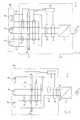
Die erfindungsgemäße photovoltaische Anlage weist einen Wechselrichter zum Einspeisen der von einem Generator der Anlage erzeugten elektrischen Energie in ein Netz, insbesondere ein Wechselstromnetz auf. Hierbei wird der Generator in eine Anzahl von Teilstrings aufgeteilt, die durch eine über eine Steuereinrichtung angesteuerte Reihenschalteinrichtung in Serie geschaltet werden können. Die Teilstrings weisen jeweils eine Anzahl von Modulen oder einzelnen Solarzellen auf, die so konfiguriert sind, dass die Leerlaufspannung eines jeden Teilstrings einen Wert aufweist, der einen zum Beispiel vom Gesetzgeber bestimmten Gefahrengrenzwert nicht übersteigt. Im Gefahrenfall bewirkt die Reihenschalteinrichtung, dass die elektrische Verbindung zwischen den Teilstrings aufgetrennt wird, so dass Spannungen bzw. Spannungsdifferenzen in den elektrischen Verbindungen zwischen dem Wechselrichter und den Teilstrings den Gefahrengrenzwert nicht mehr übersteigen können.The photovoltaic system according to the invention has an inverter for feeding the electrical energy generated by a generator of the system into a network, in particular an AC network. In this case, the generator is divided into a number of sub-strings, which can be connected in series by a controlled via a control device series switching device. The substrings each have a number of modules or individual solar cells that are configured so that the open circuit voltage of each substring has a value that does not exceed a, for example, legislator-defined hazard limit. In the case of danger, the series switching device causes the electrical connection between the substrings to be separated, so that voltages or voltage differences in the electrical connections between the inverter and the substrings can no longer exceed the danger limit.
Ein Teilstring besteht dabei üblicherweise aus in Reihe geschalteten Modulen, die wiederum in Reihe geschaltete Solarzellen umfassen. Je nach verwendetem Modultyp kann die Spannung des Moduls bereits so groß sein, dass bei einer Reihenschaltung zweier Module der Gefahrengrenzwert überschritten wird. In diesem Fall kann ein Teilstring auch aus einem einzelnen Modul bestehen. Ebenso kann ein Teilstring auch aus einer Parallelverschaltung mehrerer Strings bestehen, deren Spannung den Gefahrengrenzwert nicht überschreitet.A substring usually consists of series-connected modules, which in turn comprise series-connected solar cells. Depending on the module type used, the voltage of the module may already be so great that the danger threshold is exceeded when connecting two modules in series. In this case, a substring can also consist of a single module. Likewise, a substring can also consist of a parallel connection of several strings whose voltage does not exceed the danger threshold.
Der Gefahrengrenzwert kann regional einen unterschiedlichen, vorgeschriebenen Wert aufweisen, zum Beispiel eine Spannung von 120 V, es können aber auch abweichende Werte im Bereich zwischen 60 V und 150 V, also zum Beispiel 100 V, als Grenzwert vorgegeben werden.The hazard threshold may vary by region to a different, prescribed value For example, a voltage of 120 V, but also deviating values in the range between 60 V and 150 V, so for example 100 V, can be specified as a limit.
In einer bevorzugten Ausführung der Erfindung weist der an den Wechselrichter angeschlossene Generator mindestens drei durch die Reihenschalteinrichtung in Serie zu schaltende Teilstrings auf. Auf diese Weise kann erreicht werden, dass die gesamte Generatorspannung im optimalen Betriebspunkt des Generators einen Wert größer als die Scheitelspannung des Netzes aufweist (z. B. 350 V), wodurch die Einspeisung in das Netz ohne den Einsatz eines Hochsetzstellers im Wechselrichter möglich wird. Gleichzeitig kann die Leerlaufspannung der einzelnen Teilstrings unter dem oben angegebenen Gefahrengrenzwert verbleiben. Bei drei Teilstrings ist es allerdings häufig erforderlich, den Generator oberhalb einer Spannung zu betreiben, bei der die elektrische Leistung des Generators maximal ist, um die Scheitelspannung des Netzes zu überschreiten. Daher kann es vorteilhaft sein, mindestens vier Teilstrings in Serie zu schalten, wodurch es möglich ist, den Generator im Arbeitspunkt maximaler Leistung zu betreiben, wobei die Leerlaufspannung der einzelnen Teilstrings unterhalb eines Gefahrengrenzwertes von 120 V verbleiben kann. Bei anderen Gefahrengrenzwerten ergibt sich entsprechend eine andere Anzahl von Teilstrings, ab der dieser Effekt erreicht werden kann.In a preferred embodiment of the invention, the generator connected to the inverter has at least three partial strings to be switched in series by the series switching device. In this way it can be achieved that the entire generator voltage in the optimum operating point of the generator has a value greater than the peak voltage of the network (eg 350 V), whereby the supply to the grid is possible without the use of a boost converter in the inverter. At the same time, the no-load voltage of the individual partial strings can remain below the above-mentioned danger limit value. With three sub-strings, however, it is often necessary to operate the generator above a voltage at which the electrical power of the generator is maximum to exceed the peak voltage of the network. Therefore, it may be advantageous to connect at least four partial strings in series, whereby it is possible to operate the generator at the operating point maximum power, the open circuit voltage of the individual substrings may remain below a hazard threshold of 120 V. In the case of other hazard thresholds, a different number of partial strings results from which this effect can be achieved.
Die Reihenschalteinrichtung kann hierbei eine Anzahl von Schaltern aufweisen, die über eine Steuereinrichtung derart ansteuerbar sind, dass sie in einem Betriebszustand der photovoltaischen Anlage eine elektrische Verbindung zwischen benachbarten Teilstrings herstellen, und im potenziell gefährlichen Zustand diese Verbindung auftrennen. Die Schalter können hierbei mechanische Schalter, zum Beispiel Relais, oder Halbleiter, insbesondere Leistungs-Halbleiter wie MOSFETs, IGBTs oder Thyristoren sein.The series switching device may in this case have a number of switches which are controllable via a control device such that they produce an electrical connection between adjacent partial strings in an operating state of the photovoltaic system, and disconnect this connection in the potentially dangerous state. The switches may in this case be mechanical switches, for example relays, or semiconductors, in particular power semiconductors such as MOSFETs, IGBTs or thyristors.
Durch eine Integration der Reihenschalteinrichtung in ein Gehäuse des Wechselrichters wird zum einen eine besonders einfache Installation der Sicherungsmaßnahme erreicht. Gleichzeitig wird die Zuverlässigkeit der Auslösung der Sicherungsmaßnahme im Gefahrenfall deutlich erhöht, insbesondere wenn alle zugehörigen Komponenten im Gehäuse des Wechselrichters angeordnet sind, wo sie zumindest eine erhebliche Zeitdauer vor Beschädigung durch Rauch- und Hitzeeinwirkung, aber auch vor den in Generatornähe typischen Witterungseinflüssen geschützt sind. Ebensogut kann die Reihenschalteinrichtung am Generator angeordnet sein, wobei die Schaltelemente der Reihenschalteinrichtung entweder in einer gemeinsamen Einheit oder in separaten Einheiten an den Teilstrings oder auch zwischen den Teilstrings angeordnet sein können. Eine Anordnung am Generator bietet gegenüber der Anordnung im Wechselrichter den Vorteil, dass der Verkabelungsaufwand gegebenenfalls erheblich reduziert ist. Selbstverständlich kann die Reihenschalteinrichtung ebenso in einer separaten Box untergebracht sein, die sowohl wechselrichternah, als auch generatornah, als auch zwischen Generator und Wechselrichter platzierbar ist. Die Platzierung an geeigneter Stelle zwischen Generator und Wechselrichter ermöglicht dabei gegebenenfalls das Finden eines guten Kompromisses zwischen Schutz der Schalteinrichtung einerseits und Verkabelungsaufwand andererseits. Ferner wird hierdurch die Nach-, Auf- oder Umrüstung einer bestehenden Anlage ermöglicht.By integrating the series switching device into a housing of the inverter, on the one hand, a particularly simple installation of the safety measure is achieved. At the same time the reliability of the triggering of the safety measure in the event of danger is significantly increased, especially if all associated components are arranged in the housing of the inverter, where they are protected at least a considerable period of time from damage by smoke and heat, but also from the typical weather conditions near the generator. Just as well, the series switching device may be arranged on the generator, wherein the switching elements of the series switching device can be arranged either in a common unit or in separate units on the substrings or between the substrings. An arrangement on the generator offers over the arrangement in the inverter the advantage that the cabling effort is possibly considerably reduced. Of course, the series switching device can also be accommodated in a separate box, which is both near the inverter, as well as near the generator, as well as between the generator and inverter can be placed. The placement at a suitable location between the generator and the inverter makes it possible to find a good compromise between protection of the switching device on the one hand and cabling on the other hand, if necessary. Furthermore, this makes it possible to retrofit, upgrade or retrofit an existing system.
Da viele photovoltaische Anlagen bereits mit Kommunikationstechnologie wie Powerline-Communication oder Funktechniken wie Bluetooth, ZigBee o. ä. ausgestattet sind, die einen Datenaustausch mit entfernten Kommunikationseinheiten herstellen können, ist auch die Erreichbarkeit der Steuer- und Auslöseeinrichtung, sowie die Rückmeldung der erfolgreichen Auslösung der Sicherungsmaßnahme in vorteilhafter Weise gewährleistet. Gleichzeitig ist es so möglich, mit einem einzigen Auslösesignal eine Vielzahl von photovoltaischen Anlagen zu sichern, was eine erhebliche Zeiteinsparung im Gefahrenfall zur Folge hat.Since many photovoltaic systems are already equipped with communication technology such as powerline communication or wireless technologies such as Bluetooth, ZigBee o. Ä., Which can establish a data exchange with remote communication units, the accessibility of the control and triggering device, as well as the feedback of the successful release of the Safeguard ensured in an advantageous manner. At the same time it is possible to secure a large number of photovoltaic systems with a single trigger signal, which has a considerable time savings in the event of danger.
Optional kann die photovoltaische Anlage zusätzlich eine Parallelschalteinrichtung umfassen, die ebenso wie die Reihenschalteinrichtung eine Anzahl von Schaltern aufweist, die derart konfiguriert sind, dass sie im geschlossenen Zustand die einzelnen Teilstrings parallel zueinander schalten. Die Art der denkbaren Schalter sowie deren mögliche Anordnung in Einheiten im Wechselrichter, am Generator oder zwischen Generator und Wechselrichter entsprechen denen der Reihenschalteinrichtung.Optionally, the photovoltaic system can additionally comprise a parallel switching device which, like the series switching device, has a number of switches which are configured in such a way that they switch the individual partial strings parallel to one another in the closed state. The type of conceivable switches and their possible arrangement in units in the inverter, on the generator or between the generator and inverter correspond to those of the series switching device.
Die Parallelschalteinrichtung wird typischerweise betätigt, wenn die Reihenschalteinrichtung die elektrische Verbindung zwischen benachbarten Teilstrings aufgetrennt hat. In diesem Zustand ist ebenfalls sichergestellt, dass die in der Anlage auftretenden Spannungen bzw. Spannungsdifferenzen den Gefahrengrenzwert nicht übersteigen. Zusätzlich ist es in diesem Zustand möglich, auf einem niedrigeren Spannungsniveau des Generators weiterhin elektrische Leistung mittels des Wechselrichters in das Netz einzuspeisen. In diesem Fall ist es zur Einspeisung in das Netz notwendig, die Generatorspannung zunächst mittels eines Hochsetzstellers auf eine ausreichend hohe Gleichspannung umzusetzen. Beispielsweise kann auf diese Weise erreicht werden, dass die Einspeisung fortgesetzt werden kann, wenn längere Wartungsarbeiten im Bereich des Generators durchgeführt werden müssen, da ein Risiko für die die Wartung ausführenden Menschen durch die Reduktion der Generatorspannung ausreichend herabgesetzt werden kann. Die Fortführung der Einspeisung kann auch beim Auftreten von Fehlalarmen helfen, unnötige Einbußen der Energieausbeute der photovoltaischen Anlage zu vermeiden. Selbst im Brandfall würde eine erfindungsgemäße photovoltaische Anlage bei fortgeführter Einspeisung keine Gefahr für Rettungspersonal darstellen.The shunt device is typically actuated when the series shifter has disconnected the electrical connection between adjacent sub-strings. In this state, it is also ensured that the voltages or voltage differences occurring in the system do not exceed the danger threshold. In addition, in this state, it is possible to continue to supply electric power to the grid through the inverter at a lower voltage level of the generator. In this case, for feeding into the grid, it is necessary to first convert the generator voltage to a sufficiently high DC voltage by means of a boost converter. For example, it can be achieved in this way that the feed can be continued if longer maintenance work in the area of the generator has to be carried out, since there is a risk for the people carrying out the maintenance the reduction of the generator voltage can be sufficiently reduced. The continuation of the feed-in can also help in the event of false alarms to avoid unnecessary losses in the energy yield of the photovoltaic system. Even in the event of fire, a photovoltaic system according to the invention would not present any danger to rescue personnel if the feed were continued.
Es ist ebenfalls denkbar, die Schalter der Reihenschalteinrichtung und der Parallelschalteinrichtung gleichzeitig zu schließen, so dass die angeschlossenen Teilstrings in diesem Zustand kurzgeschlossen sind, wodurch ebenfalls eine Gefährdung durch die Generatorspannung ausgeschlossen ist.It is also conceivable to close the switches of the series switching device and the parallel switching device at the same time, so that the connected sub-strings are short-circuited in this state, which likewise precludes any danger from the generator voltage.
Alternativ kann die Kurzschlussfunktion auch durch eine zusätzliche Kurzschließeinrichtung, die zwischen den elektrischen Zuleitungen zwischen Reihenschalteinrichtung und Wechselrichter angeordnet ist, erreicht werden.Alternatively, the short-circuit function can also be achieved by an additional short-circuit device, which is arranged between the electrical supply lines between the series switching device and the inverter.
Zusätzlich können Wechselrichter und Generator durch eine DC-Trenneinrichtung voneinander getrennt werden. Die Kurzschließeinrichtung und die DC-Trenneinrichtung können hierbei ebenfalls Schalter von den im Rahmen der Reihenschalteinrichtung aufgezählten Typen aufweisen.In addition, the inverter and generator can be separated by a DC separator. The short-circuiting device and the DC disconnecting device can also have switches of the types enumerated in the context of the series switching device.
Weiterhin kann die photovoltaische Anlage optional zusätzlich eine Erdschließeinrichtung umfassen, die ebenso wie die Reihenschalteinrichtung und die Parallelschalteinrichtung eine Anzahl von Schaltern aufweist, die derart konfiguriert sind, dass sie im geschlossenen Zustand mindestens einen Anschluss mindestens eines der Teilstrings mit Erde verbinden. Die Erdschließeinrichtung kann hierbei Schalter von den im Rahmen der Reihenschalteinrichtung aufgezählten Typen aufweisen, deren mögliche Anordnung in Einheiten im Wechselrichter, am Generator oder zwischen Generator und Wechselrichter derjenigen der Reihenschalteinrichtung oder der Parallelschalteinrichtung entspricht.Furthermore, the photovoltaic system can optionally additionally comprise an earth-closing device which, like the series-connected device and the parallel-switching device, has a number of switches which are configured in such a way that they connect at least one connection of at least one of the substrings to ground in the closed state. The earth-closing device may in this case comprise switches of the types listed in the context of the series-switching device, whose possible arrangement in units in the inverter, at the generator or between the generator and the inverter corresponds to that of the series-switching device or the parallel-switching device.
Die Erdschließeinrichtung wird typischerweise betätigt, wenn die Reihenschalteinrichtung die elektrische Verbindung zwischen benachbarten Teilstrings aufgetrennt hat. In diesem Zustand könnten je nach Vorhandensein oder Fehlen einer Erdung von Teilen der photovoltaischen Anlage auftretende Spannungen an den Teilstrings gegenüber Erde den Gefahrengrenzwert übersteigen. Dies wird durch Herstellen eines definierten Potenzials an einem Anschluss der Teilstrings mittels der Erdschließeinrichtung verhindert. Die Erdschließeinrichtung kann auch in Verbindung mit der Parallelschließeinrichtung aktiviert sein.The earthing device is typically actuated when the series switching device has disconnected the electrical connection between adjacent substrings. In this condition, depending on the presence or absence of grounding of parts of the photovoltaic system, voltages on the substrings opposite ground could exceed the hazard threshold. This is prevented by establishing a defined potential at a connection of the substrings by means of the earth-closing device. The earth-closing device can also be activated in conjunction with the parallel-closing device.
Es ist ebenfalls denkbar, über die Schalter der Erdschließeinrichtung jeweils beide Anschlüsse der Teilstrings gleichzeitig mit Erde zu verbinden, so dass die angeschlossenen Teilstrings in diesem Zustand über Erde kurzgeschlossen sind, wodurch ebenfalls eine Gefährdung durch die Generatorspannung ausgeschlossen ist. Ebenso kann ein sicherer Zustand durch Herstellen einer Verbindung mit Erde zwischen allen Teilstrings erreicht werden.It is also conceivable, via the switches of Erdschließeinrichtung both connections of the substrings simultaneously to connect to earth, so that the connected substrings are shorted in this state over ground, which also a risk from the generator voltage is excluded. Likewise, a secure state can be achieved by establishing a connection with ground between all substrings.
Die Reihenschalteinrichtung, die Parallelschalteinrichtung, die Erdschließeinrichtung, die Kurzschließeinrichtung und die DC-Trenneinrichtung werden von einer zentralen Steuereinrichtung abhängig vom Vorliegen eines Betriebszustandes oder Signals, welche einer Gefahrensituation zugeordnet sind, gesteuert. Hierzu kann die Steuereinrichtung dazu eingerichtet sein, Betriebszustände der photovoltaischen Anlage, die einem Gafahrenfall zugeordnet sind, beispielsweise gefahrentypische Schwankungen in den elektrischen Kenngrößen der photovoltaischen Anlage, zu erkennen. Sie kann aber auch zum Empfang eines einem Gefahrenfall zugeordneten Signals eingerichtet sein, das beispielsweise vom Wechselrichter erzeugt wird, zum Beispiel wenn der Wechselrichter eine Inselnetz-Situation erkennt, oder auch von einer separaten Sensoreinrichtung oder durch eine manuelle Notabschalteinrichtung. Eine Übertragung des Signals zur Steuereinrichtung kann mittels einer elektrischen Steuerleitung, einer drahtlosen Verbindung oder auch mittels einer Übertragung über die vorhandenen Gleichspannungs- oder Wechselspannungsleitungen an die Steuereinrichtung erfolgen. Als drahtlose Verbindung kommen hier einerseits Funkverbindungen in Frage, aber auch andere Möglichkeiten drahtloser Signalübertragung wie beispielsweise Infrarot, Schall, Ultraschall, mechanische Wirkübertrager, hydraulische Wirkübertrager oder pneumatische Wirkübertrager.The series switching device, the parallel switching device, the earth-closing device, the short-circuiting device and the DC separating device are controlled by a central control device as a function of the presence of an operating state or signal associated with a dangerous situation. For this purpose, the control device can be set up to recognize operating states of the photovoltaic system which are associated with a parking case, for example, typical fluctuations in the electrical parameters of the photovoltaic system. However, it can also be set up to receive a signal associated with a danger, which is generated, for example, by the inverter, for example if the inverter detects an isolated grid situation, or else by a separate sensor device or by a manual emergency shutdown device. A transmission of the signal to the control device can take place by means of an electrical control line, a wireless connection or by means of a transmission over the existing DC or AC voltage lines to the control device. As a wireless connection come here on the one hand radio communications in question, but also other possibilities wireless signal transmission such as infrared, sound, ultrasound, mechanical repeaters, hydraulic impact or pneumatic Wirkübertrager.
In einem erfindungsgemäßen Verfahren wird die Anlage zunächst bei einer Spannung des Generators oberhalb des Gefahrengrenzwertes betrieben. In diesem Betriebszustand arbeitet die Anlage typischerweise besonders effizient. Sobald ein Gefahrenfall detektiert wird, wird die Anlage auf eine Generatorspannung reduziert, die unterhalb des Gefahrengrenzwertes liegt. Das Verlassen des Arbeitspunktes mit einer Generatorspannung oberhalb des Gefahrengrenzwertes und das Regeln auf einen neuen Arbeitspunkt mit einer Generatorspannung unterhalb des Gefahrengrenzwertes wird hierbei typischerweise durch die Spannungs- oder Stromregelung des Wechselrichters bewerkstelligt.In a method according to the invention, the system is initially operated at a voltage of the generator above the danger threshold. In this operating state, the system typically works very efficiently. As soon as a hazard is detected, the system is reduced to a generator voltage that is below the danger threshold. Leaving the operating point with a generator voltage above the danger threshold and the regulation to a new operating point with a generator voltage below the danger threshold is typically accomplished by the voltage or current control of the inverter.
Eine Gefahrensituation bzw. ein Gefahrenfall kann vorliegen, wenn eine Inselnetz-Situation eintritt, das heißt wenn der Wechselrichter vom Netz getrennt wird, oder das Netz abgeschaltet ist, wenn ein Lichtbogen oder ein Erdschluss in elektrischen Verbindungen der photovoltaischen Anlage erkannt wird oder wenn eine Generatortrenneinrichtung am Wechselrichter ausgelöst wird, z. B. ein sogenannter Electronic Solar Switch. Eine Gefahrensituation bzw. ein Gefahrenfall kann ebenfalls vorliegen, wenn eine manuelle Notabschalteinrichtung betätigt wird, wenn gefahrentypische Schwankungen in elektrischen Kenngrößen der photovoltaischen Anlage erkannt werden oder wenn externe Sensoren wie beispielsweise Temperaturfühler, Rauchmelder oder Infrarotdetektoren ansprechen. Sofern die photovoltaische Anlage in einer Datenverbindung zu benachbarten, weiteren photovoltaischen Anlagen oder Wechselrichtern oder zu anderen Kommunikationseinheiten steht, kann ein einer Gefahrensituation zugeordnetes Signal auch von einer Anlage zur nächsten übertragen werden, so dass die Anlagen gemeinsam auf die Gefahrensituation reagieren können.A hazardous situation or a dangerous situation may exist if an isolated grid situation occurs, that is, if the inverter is disconnected from the grid, or the grid is switched off, if an arc or a ground fault in electrical connections of the photovoltaic system is detected or if a generator disconnecting device at the Inverter is triggered, z. B. a so-called electronic solar switch. A dangerous situation or a dangerous situation can also be present if a manual emergency shutdown device is actuated, if typical fluctuations in electrical parameters of the photovoltaic system are detected or if external sensors such as temperature sensors, smoke detectors or infrared detectors respond. If the photovoltaic system is in a data connection to neighboring, further photovoltaic systems or inverters or to other communication units, a signal associated with a hazardous situation signal can also be transmitted from one system to another, so that the systems can respond together to the dangerous situation.
Eine Fortführung der Einspeisung elektrischer Leistung in ein Netz, an das die photovoltaische Anlage angeschlossen ist, kann trotz Reduktion der Generatorspannung erreicht werden, indem die auf einen Wert unterhalb eines Gefahrengrenzwertes reduzierte Generatorspannung mittels eines Hochsetzstellers zunächst auf einen ausreichend hohen Gleichspannungswert angehoben wird, mit dem eine Wechselrichterbrücke die Wechselspannung zur Einspeisung in das Netz erzeugt. Zum Beispiel kann der Hochsetzsteller eine Generatorspannung kleiner 120 V auf eine Zwischenkreisspannung größer 325 V anheben, so dass die direkte Einspeisung elektrischer Leistung in ein öffentliches Netz möglich ist.A continuation of the supply of electrical power in a network to which the photovoltaic system is connected, despite reduction of the generator voltage can be achieved by the reduced to a value below a danger threshold generator voltage is first raised by a boost converter to a sufficiently high DC voltage with the an inverter bridge generates the AC voltage for feeding into the grid. For example, the step-up converter can raise a generator voltage of less than 120 V to an intermediate circuit voltage of greater than 325 V, so that the direct supply of electrical power to a public grid is possible.
In einer bevorzugten Ausführungsform des erfindungsgemäßen Verfahrens werden die einzelnen Teilstrings des Generators beim Betrieb der photovoltaischen Anlage oberhalb des Gefahrengrenzwertes in einer Reihenschaltung betrieben, die beispielsweise durch die vorbeschriebene Reihenschalteinrichtung gewährleistet werden kann, während die reduzierte Generatorspannung dadurch erreicht wird, dass die Teilstrings in einer Parallelschaltung betrieben werden, die beispielsweise durch die vorbeschriebene Parallelschalteinrichtung gewährleistet werden kann. Hierbei wird bei Detektion des Gefahrenfalles zwischen Reihenschaltung und Parallelschaltung der Teilstrings gewechselt.In a preferred embodiment of the method according to the invention, the individual partial strings of the generator are operated during operation of the photovoltaic system above the danger threshold in a series circuit, which can be ensured for example by the above-described series switching device, while the reduced generator voltage is achieved in that the substrings in a parallel circuit operated, which can be ensured for example by the above-described parallel switching device. In this case, the detection of the danger case between series connection and parallel connection of the substrings is changed.
Optional kann das Verfahren zusätzlich um einen Verfahrensschritt erweitert sein, in dem in Reaktion auf die Detektion des Gefahrenfalles eine Herstellung einer elektrischen Verbindung mindestens eines Anschlusses mindestens eines der Teilstrings mit Erde erfolgt, wodurch ein definiertes Potenzial dieses Anschlusses gegenüber Erde hergestellt wird. Eine solche Verbindung mit Erde kann beispielsweise durch die vorbeschriebene Erdschließeinrichtung gewährleistet werden.Optionally, the method can additionally be extended by a method step in which, in response to the detection of the danger case, an electrical connection of at least one connection of at least one of the substrings to ground is established, whereby a defined potential of this connection with respect to ground is produced. Such a connection to earth can be ensured, for example, by the above-described earth-closing device.
In einer mit erwogenen Variante des erfindungsgemäßen Verfahrens wird die Regelung der Generatorspannung auf einen Wert unterhalb des Gefahrengrenzwertes dadurch erreicht, dass der gesamte Generator oder Teilstrings des Generators kurzgeschlossen werden, gegebenenfalls auch über Erde. Dieses Kurzschließen des Generators kann auch als zusätzliche Maßnahme erfolgen, nachdem die Generatorspannung zunächst auf einen Wert unterhalb des Gefahrengrenzwertes reduziert wurde, zum Beispiel wenn ein weiteres Einspeisen elektrischer Leistung in ein Netz nicht mehr möglich ist. In diesem Fall würde die Generatorspannung ohne ein Kurzschließen des Generators andernfalls möglicherweise auf Werte oberhalb des Gefahrengrenzwertes ansteigen. Das Kurzschließen des Generators kann hierbei zum Beispiel ausgelöst werden, wenn eine Inselnetz-Situation vom Wechselrichter detektiert wird.In a contemplated variant of the method according to the invention, the regulation of the generator voltage to a value below the danger threshold is achieved in that the entire generator or partial strings of the generator are short-circuited, possibly also over ground. This short-circuiting of the generator can also be done as an additional measure after the generator voltage has initially been reduced to a value below the hazard threshold, for example, when further feeding electric power into a network is no longer possible. Otherwise, without generator shorting, the generator voltage would otherwise rise to levels above the hazard threshold. The short-circuiting of the generator can in this case be triggered, for example, if an isolated grid situation is detected by the inverter.
Weitere Eigenschaften, Merkmale und Vorteile der Erfindung ergeben sich aus der nachfolgenden detaillierten Beschreibung von Ausführungsbeispielen der Erfindung anhand der beigefügten Zeichnungen.Further features, features and advantages of the invention will become apparent from the following detailed description of embodiments of the invention with reference to the accompanying drawings.
Optional kann zwischen den Verbindungsleitungen
Die Steuereinrichtung
Darüber hinaus sind viele weitere, hier nicht gezeigte Ausführungsvarianten der erfindungsgemäßen Vorrichtung möglich, von denen sich die meisten in einfacher Weise durch Variation und/oder Kombination der Anordnungen von Schaltern, Einheiten und Einrichtungen am Generator
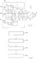
Wenn man die Teilstrings bei Detektion einer Gefahrensituation von einer Reihenschaltung in eine Parallelschaltung umkonfiguriert, ergibt sich eine zweite Leistungskennlinie
Sofern der Generator in Reihenschaltung verbleibt, das heißt im Gefahrenfall im Arbeitspunkt
BezugszeichenlisteLIST OF REFERENCE NUMBERS
- 11
- Photovoltaische AnlagePhotovoltaic system
- 2020
- Wechselrichterinverter
- 3030
- Netznetwork
- 4040
- Steuereinrichtungcontrol device
- 5050
- ReihenschalteinrichtungSeries switching device
- 6060
- ParallelschalteinrichtungParallel switching device
- 7070
- Generatorgenerator
- 70a–70c70a-70c
- Teilstringssubstring
- 8080
- DC-TrenneinrichtungDC disconnection
- 110110
- KurzschließeinrichtungShunt devices
- 120120
- Verbindungsleitungconnecting line
- 130130
- Verbindungsleitungconnecting line
- 140140
- ErdschließeinrichtungErdschließeinrichtung
- 150150
- WechselrichtergehäuseInverter case
- 160a, 160b160a, 160b
- Einheiten zur Anordnung zwischen TeilstringsUnits for arrangement between substrings
- 170a–170c170a-170c
- Einheiten zur Anordnung an TeilstringsUnits for arrangement on substrings
- 200, 210, 220200, 210, 220
- Verfahrensschrittesteps
- 230230
- Verfahrensschrittstep
- 300300
- Erster Arbeitspunkt maximaler LeistungFirst operating point of maximum power
- 310310
- Zweiter Arbeitspunkt maximaler LeistungSecond operating point of maximum power
- 320320
- KurzschlusspunktShort paragraph
- 330330
- Dritter ArbeitspunktThird working point
- 340340
- Erste LeistungskennlinieFirst performance characteristic
- 350350
- Zweite LeistungskennlinieSecond performance characteristic
ZITATE ENTHALTEN IN DER BESCHREIBUNG QUOTES INCLUDE IN THE DESCRIPTION
Diese Liste der vom Anmelder aufgeführten Dokumente wurde automatisiert erzeugt und ist ausschließlich zur besseren Information des Lesers aufgenommen. Die Liste ist nicht Bestandteil der deutschen Patent- bzw. Gebrauchsmusteranmeldung. Das DPMA übernimmt keinerlei Haftung für etwaige Fehler oder Auslassungen.This list of the documents listed by the applicant has been generated automatically and is included solely for the better information of the reader. The list is not part of the German patent or utility model application. The DPMA assumes no liability for any errors or omissions.
Zitierte PatentliteraturCited patent literature
- DE 102005018173[0003]DE 102005018173[0003]
- DE 102006060815[0004, 0004]DE 102006060815[0004, 0004]
Claims (22)
Translated fromGermanPriority Applications (6)
| Application Number | Priority Date | Filing Date | Title |
|---|---|---|---|
| DE102010017747ADE102010017747A1 (en) | 2010-05-03 | 2010-07-05 | Method for limiting the generator voltage of a photovoltaic system in case of danger and photovoltaic system |
| JP2013508474AJP2013534125A (en) | 2010-05-03 | 2011-05-03 | Method and photovoltaic installation for limiting the generator voltage of photovoltaic installations in hazardous situations |
| EP11718706.2AEP2567406B1 (en) | 2010-05-03 | 2011-05-03 | Method for limiting the generator voltage of a photovoltaic installation in case of danger and photovoltaic installation |
| CN201180029268.2ACN102939661B (en) | 2010-05-03 | 2011-05-03 | Method and photovoltaic system for limiting the generator voltage of a photovoltaic system in hazardous situations |
| PCT/EP2011/057043WO2011138319A1 (en) | 2010-05-03 | 2011-05-03 | Method for limiting the generator voltage of a photovoltaic installation in case of danger and photovoltaic installation |
| US13/667,607US8837098B2 (en) | 2010-05-03 | 2012-11-02 | Method for limiting the generator voltage of a photovoltaic installation in case of danger and photovoltaic installation |
Applications Claiming Priority (3)
| Application Number | Priority Date | Filing Date | Title |
|---|---|---|---|
| DE102010016753 | 2010-05-03 | ||
| DE102010016753.3 | 2010-05-03 | ||
| DE102010017747ADE102010017747A1 (en) | 2010-05-03 | 2010-07-05 | Method for limiting the generator voltage of a photovoltaic system in case of danger and photovoltaic system |
Publications (1)
| Publication Number | Publication Date |
|---|---|
| DE102010017747A1true DE102010017747A1 (en) | 2011-11-03 |
Family
ID=44786290
Family Applications (2)
| Application Number | Title | Priority Date | Filing Date |
|---|---|---|---|
| DE102010017747ACeasedDE102010017747A1 (en) | 2010-05-03 | 2010-07-05 | Method for limiting the generator voltage of a photovoltaic system in case of danger and photovoltaic system |
| DE102010017746ACeasedDE102010017746A1 (en) | 2010-05-03 | 2010-07-05 | Method for limiting the generator voltage of a photovoltaic system in case of danger and photovoltaic system |
Family Applications After (1)
| Application Number | Title | Priority Date | Filing Date |
|---|---|---|---|
| DE102010017746ACeasedDE102010017746A1 (en) | 2010-05-03 | 2010-07-05 | Method for limiting the generator voltage of a photovoltaic system in case of danger and photovoltaic system |
Country Status (6)
| Country | Link |
|---|---|
| US (2) | US8837098B2 (en) |
| EP (2) | EP2567406B1 (en) |
| JP (2) | JP2013534125A (en) |
| CN (2) | CN102939660B (en) |
| DE (2) | DE102010017747A1 (en) |
| WO (2) | WO2011138319A1 (en) |
Cited By (3)
| Publication number | Priority date | Publication date | Assignee | Title |
|---|---|---|---|---|
| DE102011015392A1 (en)* | 2011-03-29 | 2012-10-04 | Adensis Gmbh | Photovoltaic system for electric power generation, has control apparatus for triggering control signals for simultaneous or staggered closing of switching elements, if voltage across one element exceeds first prescribed limit value |
| DE102011017362A1 (en)* | 2011-04-16 | 2012-10-18 | Adensis Gmbh | Three-switch surge protection |
| DE102016115295A1 (en)* | 2016-08-17 | 2018-02-22 | Sma Solar Technology Ag | Separator for a photovoltaic string |
Families Citing this family (42)
| Publication number | Priority date | Publication date | Assignee | Title |
|---|---|---|---|---|
| DE102010017747A1 (en)* | 2010-05-03 | 2011-11-03 | Sma Solar Technology Ag | Method for limiting the generator voltage of a photovoltaic system in case of danger and photovoltaic system |
| DE102011109615A1 (en)* | 2010-12-02 | 2012-06-06 | Würth Solar Gmbh & Co. Kg | Photovoltaic module Combination of several photovoltaic modules |
| US9184594B2 (en) | 2011-06-03 | 2015-11-10 | Schneider Electric Solar Inverters Usa, Inc. | Photovoltaic voltage regulation |
| EP2587334A1 (en)* | 2011-10-24 | 2013-05-01 | Imec | Reconfigurable PV configuration |
| DE202011109688U1 (en) | 2011-12-31 | 2012-03-01 | Raik Stiebert | Safety-related design and activation of photovoltaic systems and safety-related grounding of extinguishing equipment |
| DE102012101340B4 (en)* | 2012-02-20 | 2015-11-19 | Sma Solar Technology Ag | Protection of photovoltaic modules of a photovoltaic generator against overvoltages to earth |
| US20130271888A1 (en)* | 2012-04-16 | 2013-10-17 | Sma Solar Technology Ag | Photovoltaic System and Apparatus for Operating a Photovoltaic System |
| DE102012104383B4 (en) | 2012-05-22 | 2014-03-13 | Solarworld Innovations Gmbh | Control for a photovoltaic module arrangement, photovoltaic module arrangement and inverter for a photovoltaic module arrangement |
| DE102012104384B4 (en) | 2012-05-22 | 2014-03-13 | Solarworld Innovations Gmbh | Single-pole switching unit for limiting the flow of energy in a series connection of photovoltaic modules, photovoltaic module arrangement and photovoltaic module |
| DE102012110110B4 (en)* | 2012-10-23 | 2016-12-08 | Sma Solar Technology Ag | Inverter, method for operating an inverter and power supply system with an inverter |
| EP2770539A1 (en)* | 2013-02-20 | 2014-08-27 | Total Marketing Services | Electronic management system for electricity generating cells, electricity generating system and method for electronically managing energy flow |
| US9680305B2 (en)* | 2013-03-14 | 2017-06-13 | Hiq Solar, Inc. | Implementation of fire safety shutdown for solar panels with high reliability |
| US9697961B2 (en)* | 2013-03-15 | 2017-07-04 | Solantro Semiconductor Corp. | Photovoltaic bypass switching |
| US9524832B2 (en) | 2013-03-15 | 2016-12-20 | Solantro Semiconductor Corp | Intelligent safety disconnect switching |
| US9780234B2 (en) | 2013-06-14 | 2017-10-03 | Solantro Semiconductor Corp. | Photovoltaic bypass and output switching |
| DE102013110240B4 (en)* | 2013-09-17 | 2017-09-07 | Sma Solar Technology Ag | Circuit arrangement for a photovoltaic inverter for off-load relief with short-circuit switches and uses of the circuit arrangement |
| DE102013221444B4 (en)* | 2013-10-22 | 2019-02-07 | Kaco New Energy Gmbh | Inverter system and power supply device |
| DE102013221446A1 (en)* | 2013-10-22 | 2015-04-23 | Kaco New Energy Gmbh | Inverter system and PV system |
| US9799779B2 (en)* | 2013-11-08 | 2017-10-24 | The Board Of Trustees Of The University Of Illinois | Systems and methods for photovoltaic string protection |
| JP3189106U (en) | 2013-12-12 | 2014-02-20 | ティー・エス・ビー株式会社 | Solar power system |
| US9843193B2 (en) | 2014-07-30 | 2017-12-12 | Robert Getsla | Safety shutdown system for photovoltaic power generators |
| US10992255B2 (en) | 2014-10-28 | 2021-04-27 | Sunpower Corporation | Photovoltaic module or array shutdown |
| AU2015364718B2 (en) | 2014-12-16 | 2019-11-28 | Marici Holdings The Netherlands B.V. | Energy panel arrangement power dissipation |
| WO2016123305A1 (en) | 2015-01-28 | 2016-08-04 | Abb Technology Ag | Energy panel arrangement shutdown |
| WO2016134356A1 (en) | 2015-02-22 | 2016-08-25 | Abb Technology Ag | Photovoltaic string reverse polarity detection |
| US9812869B2 (en)* | 2016-03-21 | 2017-11-07 | Solarcity Corporation | Rapid shutdown and safety disconnect for hybrid PV systems |
| KR101712823B1 (en)* | 2016-08-18 | 2017-03-22 | 주식회사 광명전기 | Photovoltaic solar connection board having bypass function for fire prevention |
| CN115473211A (en)* | 2016-09-12 | 2022-12-13 | 菲尼克斯电气公司 | DC Generator, DC Hybrid Switching Mechanism, Application and Method |
| CN106330090B (en)* | 2016-10-17 | 2018-05-22 | 中国葛洲坝集团电力有限责任公司 | A kind of intelligent temperature control photovoltaic array system |
| DE102016125219B4 (en)* | 2016-12-21 | 2019-01-17 | Sma Solar Technology Ag | Circuit for limiting voltage in a photovoltaic field, photovoltaic field and voltage limiting method |
| DE102017102771A1 (en)* | 2017-02-13 | 2018-08-16 | Sma Solar Technology Ag | Method for determining the maximum possible power of a PV system and PV system |
| US10672918B2 (en)* | 2017-07-19 | 2020-06-02 | Solantro Semiconductor Corp. | Photovoltaic panel rapid shutdown and recovery |
| DE102017007024A1 (en)* | 2017-07-25 | 2019-01-31 | Kostal Industrie Elektrik Gmbh | Photovoltaic inverter assembly and method of operating such |
| CN107505877A (en)* | 2017-09-25 | 2017-12-22 | 国网山东省电力公司莱阳市供电公司 | A kind of intelligent photovoltaic electricity generation system protector |
| DE102018108472A1 (en)* | 2018-04-10 | 2019-10-10 | Sma Solar Technology Ag | Photovoltaic power generation plant, supply line for a power plant, mating plug and inverter |
| DE102018219293A1 (en)* | 2018-11-12 | 2020-05-14 | Kaco New Energy Gmbh | Inverter |
| CN109245711B (en)* | 2018-11-26 | 2020-02-28 | 海宁昱能电子有限公司 | Photovoltaic system safety protection equipment |
| DE102020102399A1 (en)* | 2020-01-31 | 2021-08-05 | Eaton Intelligent Power Limited | CIRCUIT PROTECTION DEVICE AND SYSTEM WITH POWER SUPPLY CONVERSION AND CONTROL FOR DC LOADS |
| DE102020129918A1 (en) | 2020-11-12 | 2022-05-12 | Sma Solar Technology Ag | Device and method for grounding a DC voltage network |
| CN114006416A (en)* | 2021-12-28 | 2022-02-01 | 北京思凌科半导体技术有限公司 | Power supply output power configuration system |
| KR102688738B1 (en)* | 2022-07-25 | 2024-07-26 | (주)한빛이노텍 | Enhanced solar photovoltaic power generation system for blocking earth fault |
| ES2967960A1 (en)* | 2023-11-13 | 2024-05-06 | Energias Renovables Erin S L | Voltage control and disconnection device for photovoltaic modules for string (Machine-translation by Google Translate, not legally binding) |
Citations (5)
| Publication number | Priority date | Publication date | Assignee | Title |
|---|---|---|---|---|
| US6593520B2 (en)* | 2000-02-29 | 2003-07-15 | Canon Kabushiki Kaisha | Solar power generation apparatus and control method therefor |
| DE102005018173A1 (en) | 2005-04-19 | 2006-10-26 | Aixcon Elektrotechnik Gmbh | Photovoltaic device safe interruption method, involves attaching switching device in direct proximity to generator field within or outside structure, where device switches field on demand into low-energy operating point by control line |
| DE102006023563A1 (en)* | 2006-05-19 | 2007-11-22 | Kostal Industrie Elektrik Gmbh | Photovoltaic system for transforming of solar power into electricity, has strings with solar modules attached with transducers, where one of transducers is charged with output voltage of series connection of strings by using switching units |
| DE102006060815A1 (en) | 2006-09-21 | 2008-06-19 | Res Gmbh | Solar energy generation plant is made of one or multiple parallel strings made of photovoltaic modules and feed in to low voltage network by inverters |
| DE102007032605A1 (en)* | 2007-07-11 | 2009-02-05 | Robert Maier | Fotovoltaikanlage |
Family Cites Families (43)
| Publication number | Priority date | Publication date | Assignee | Title |
|---|---|---|---|---|
| US4333136A (en)* | 1979-11-26 | 1982-06-01 | Baker Richard H | Solar powered automatic turn-on control (SPA-TOC) unit and method |
| JPH07177652A (en)* | 1993-12-17 | 1995-07-14 | Canon Inc | Photovoltaic system and protection method for photovoltaic system |
| JP3271730B2 (en)* | 1994-04-28 | 2002-04-08 | キヤノン株式会社 | Power generation system charge control device |
| JPH09182279A (en)* | 1995-10-26 | 1997-07-11 | Nitto Kogyo Kk | Short-circuit detection device in solar power generation system |
| JP3700809B2 (en)* | 1997-09-29 | 2005-09-28 | 積水樹脂株式会社 | Solar cell device |
| JP2000269531A (en)* | 1999-01-14 | 2000-09-29 | Canon Inc | Solar cell module, building material with solar cell module, solar cell module enclosure, and solar power generation device |
| JP3469807B2 (en)* | 1999-03-24 | 2003-11-25 | 鐘淵化学工業株式会社 | Solar cell power generation device, wiring device for the device, and wiring structure |
| JP2001068706A (en)* | 1999-08-25 | 2001-03-16 | Sanyo Electric Co Ltd | Solar cell equipment |
| JP2004334704A (en)* | 2003-05-09 | 2004-11-25 | Canon Inc | Power conversion device and control method thereof, and solar power generation device |
| US7016793B2 (en)* | 2003-10-01 | 2006-03-21 | General Electric Company | Method and apparatus for anti-islanding protection of distributed generations |
| US7972437B2 (en)* | 2004-03-22 | 2011-07-05 | The Regents Of The University Of California | Hollow nanocrystals and method of making |
| JP4101212B2 (en)* | 2004-06-29 | 2008-06-18 | シャープ株式会社 | Power circuit |
| US8204709B2 (en)* | 2005-01-18 | 2012-06-19 | Solar Sentry Corporation | System and method for monitoring photovoltaic power generation systems |
| JP2008228558A (en)* | 2006-11-30 | 2008-09-25 | Beijing Hi-Tech Wealth Investment & Development Co Ltd | Method, apparatus and system for power supply using photovoltaic cell |
| US8816535B2 (en)* | 2007-10-10 | 2014-08-26 | Solaredge Technologies, Ltd. | System and method for protection during inverter shutdown in distributed power installations |
| US7772716B2 (en)* | 2007-03-27 | 2010-08-10 | Newdoll Enterprises Llc | Distributed maximum power point tracking system, structure and process |
| US7768751B2 (en)* | 2008-01-29 | 2010-08-03 | Advanced Energy Industries, Inc. | System and method for ground fault detection and interruption |
| FR2923653B1 (en)* | 2007-11-08 | 2009-11-27 | Harald Hauf | OPERATING METHOD AND DEVICE FOR CONTROLLING AN ENERGY PLANT WITH PHOTOVOLTAIC MODULES. |
| US8018748B2 (en)* | 2007-11-14 | 2011-09-13 | General Electric Company | Method and system to convert direct current (DC) to alternating current (AC) using a photovoltaic inverter |
| CN105244905B (en)* | 2007-12-05 | 2019-05-21 | 太阳能安吉有限公司 | Release mechanism in distributed power device is waken up and method for closing |
| DE102008014129B4 (en)* | 2008-03-13 | 2009-12-31 | Moeller Gmbh | Protection device for solar panels |
| EP2104200B1 (en)* | 2008-03-22 | 2019-02-27 | SMA Solar Technology AG | Method for controlling a multi-string inverter for photovoltaic systems |
| DE102008021654B3 (en)* | 2008-04-30 | 2009-12-10 | Insta Elektro Gmbh | Photovoltaic system operating method, involves analyzing temporal lapse of voltage value to determine operational voltage fluctuations and voltage modulations for data transfer from internal control unit to central control unit |
| EP2311163A4 (en)* | 2008-07-01 | 2013-08-21 | Satcon Technology Corp | PHOTOVOLTAIC CONTINUOUS / CONTINUOUS MICROCONVERTER |
| US9048353B2 (en)* | 2008-07-01 | 2015-06-02 | Perfect Galaxy International Limited | Photovoltaic DC/DC micro-converter |
| DE102008039205A1 (en) | 2008-08-22 | 2010-04-22 | EPROTECH Reimann e.K. Jürgen Reimann | Device and method for monitoring individual photovoltaic modules of a photovoltaic system |
| DE102008050402B4 (en)* | 2008-10-04 | 2025-03-20 | Sew-Eurodrive Gmbh & Co Kg | Circuit arrangement with a boost converter and inverter circuit with such a circuit arrangement |
| ES2338088B8 (en)* | 2008-10-30 | 2011-08-04 | Asea Brown Boveri, S.A | SYSTEM AND METHOD OF OPTIMIZATION OF ENERGY IN PHOTOVOLTAIC GENERATORS. |
| WO2010078303A2 (en)* | 2008-12-29 | 2010-07-08 | Atonometrics, Inc. | Electrical safety shutoff system and devices for photovoltaic modules |
| DE102009019831A1 (en)* | 2009-05-04 | 2010-11-11 | Voltwerk Electronics Gmbh | circuitry |
| DE102009032288A1 (en)* | 2009-07-09 | 2011-01-13 | Kostal Industrie Elektrik Gmbh | photovoltaic system |
| EP2296244B1 (en)* | 2009-08-06 | 2015-02-18 | SMA Solar Technology AG | Method and device for connecting at least one string of a photovoltaic assembly with an inverter |
| US20110090607A1 (en)* | 2009-10-20 | 2011-04-21 | Luebke Charles J | String and system employing direct current electrical generating modules and a number of string protectors |
| JP2011120449A (en)* | 2009-10-29 | 2011-06-16 | Sanyo Electric Co Ltd | Power generation system, control device, and switching circuit |
| KR101097260B1 (en)* | 2009-12-15 | 2011-12-22 | 삼성에스디아이 주식회사 | Grid-connected energy storage system and method for controlling grid-connected energy storage system |
| US9042145B2 (en)* | 2010-01-29 | 2015-05-26 | Platinum Gmbh | Circuit configuration with a step-up converter, and inverter circuit having such a circuit configuration |
| DE102010006124B4 (en)* | 2010-01-29 | 2015-04-09 | Platinum Gmbh | Circuit arrangement with a boost converter and inverter circuit with such a circuit arrangement |
| DE102010012294B4 (en)* | 2010-03-23 | 2012-04-26 | Adensis Gmbh | Photovoltaic system with potential reduction |
| DE102010017747A1 (en)* | 2010-05-03 | 2011-11-03 | Sma Solar Technology Ag | Method for limiting the generator voltage of a photovoltaic system in case of danger and photovoltaic system |
| US20120050924A1 (en)* | 2010-08-24 | 2012-03-01 | Sanyo Electric Co., Ltd. | Current collecting box for photovoltaic power generation |
| DE102010055550A1 (en)* | 2010-12-22 | 2012-06-28 | Sma Solar Technology Ag | Inverter, power plant and method of operating a power plant |
| US8547669B2 (en)* | 2011-01-12 | 2013-10-01 | Schneider Electric USA, Inc. | Arc fault mitigation for photovoltaic systems |
| US9350175B2 (en)* | 2012-04-17 | 2016-05-24 | General Electric Company | Input relay architecture for rectifying power converters and suitable for AC or DC source power |
- 2010
- 2010-07-05DEDE102010017747Apatent/DE102010017747A1/ennot_activeCeased
- 2010-07-05DEDE102010017746Apatent/DE102010017746A1/ennot_activeCeased
- 2011
- 2011-05-03WOPCT/EP2011/057043patent/WO2011138319A1/enactiveApplication Filing
- 2011-05-03JPJP2013508474Apatent/JP2013534125A/enactivePending
- 2011-05-03EPEP11718706.2Apatent/EP2567406B1/enactiveActive
- 2011-05-03JPJP2013508471Apatent/JP5830802B2/enactiveActive
- 2011-05-03EPEP11717637.0Apatent/EP2567405B1/enactiveActive
- 2011-05-03CNCN201180029266.3Apatent/CN102939660B/enactiveActive
- 2011-05-03WOPCT/EP2011/057035patent/WO2011138314A1/enactiveApplication Filing
- 2011-05-03CNCN201180029268.2Apatent/CN102939661B/enactiveActive
- 2012
- 2012-11-02USUS13/667,607patent/US8837098B2/enactiveActive
- 2012-11-02USUS13/667,532patent/US20130058140A1/ennot_activeAbandoned
Patent Citations (5)
| Publication number | Priority date | Publication date | Assignee | Title |
|---|---|---|---|---|
| US6593520B2 (en)* | 2000-02-29 | 2003-07-15 | Canon Kabushiki Kaisha | Solar power generation apparatus and control method therefor |
| DE102005018173A1 (en) | 2005-04-19 | 2006-10-26 | Aixcon Elektrotechnik Gmbh | Photovoltaic device safe interruption method, involves attaching switching device in direct proximity to generator field within or outside structure, where device switches field on demand into low-energy operating point by control line |
| DE102006023563A1 (en)* | 2006-05-19 | 2007-11-22 | Kostal Industrie Elektrik Gmbh | Photovoltaic system for transforming of solar power into electricity, has strings with solar modules attached with transducers, where one of transducers is charged with output voltage of series connection of strings by using switching units |
| DE102006060815A1 (en) | 2006-09-21 | 2008-06-19 | Res Gmbh | Solar energy generation plant is made of one or multiple parallel strings made of photovoltaic modules and feed in to low voltage network by inverters |
| DE102007032605A1 (en)* | 2007-07-11 | 2009-02-05 | Robert Maier | Fotovoltaikanlage |
Cited By (4)
| Publication number | Priority date | Publication date | Assignee | Title |
|---|---|---|---|---|
| DE102011015392A1 (en)* | 2011-03-29 | 2012-10-04 | Adensis Gmbh | Photovoltaic system for electric power generation, has control apparatus for triggering control signals for simultaneous or staggered closing of switching elements, if voltage across one element exceeds first prescribed limit value |
| DE102011017362A1 (en)* | 2011-04-16 | 2012-10-18 | Adensis Gmbh | Three-switch surge protection |
| US8743521B2 (en) | 2011-04-16 | 2014-06-03 | Adensis Gmbh | Photovoltaic system with overvoltage protection |
| DE102016115295A1 (en)* | 2016-08-17 | 2018-02-22 | Sma Solar Technology Ag | Separator for a photovoltaic string |
Also Published As
| Publication number | Publication date |
|---|---|
| WO2011138314A1 (en) | 2011-11-10 |
| EP2567406B1 (en) | 2015-07-29 |
| JP2013530664A (en) | 2013-07-25 |
| US20130057989A1 (en) | 2013-03-07 |
| JP5830802B2 (en) | 2015-12-09 |
| US20130058140A1 (en) | 2013-03-07 |
| DE102010017746A1 (en) | 2011-11-03 |
| EP2567405B1 (en) | 2015-09-16 |
| JP2013534125A (en) | 2013-08-29 |
| CN102939661A (en) | 2013-02-20 |
| EP2567406A1 (en) | 2013-03-13 |
| EP2567405A1 (en) | 2013-03-13 |
| CN102939660A (en) | 2013-02-20 |
| CN102939661B (en) | 2016-03-16 |
| US8837098B2 (en) | 2014-09-16 |
| WO2011138319A1 (en) | 2011-11-10 |
| CN102939660B (en) | 2016-10-05 |
Similar Documents
| Publication | Publication Date | Title |
|---|---|---|
| EP2567406B1 (en) | Method for limiting the generator voltage of a photovoltaic installation in case of danger and photovoltaic installation | |
| DE102008052037B3 (en) | solar module | |
| EP2920858B1 (en) | Method and device for protecting several strings of a photovoltaic generator from return currents | |
| WO2018046653A1 (en) | Photovoltaic system, direct current hybrid switching device, use and method for switching a photovoltaic string on and off | |
| WO2009006879A2 (en) | Photovoltaic system | |
| WO2013026539A1 (en) | Socket for a solar panel with a protective circuit | |
| DE102012104384A1 (en) | Single-pole switching unit for limiting the flow of energy in a series connection of photovoltaic modules, photovoltaic module arrangement and photovoltaic module | |
| DE102013101314A1 (en) | Safe photovoltaic system | |
| WO2012079742A1 (en) | Method for disconnecting a photovoltaic assembly and photovoltaic assembly | |
| DE102016117049A1 (en) | Multi-strand photovoltaic system, method for operating such and reverse current protection circuit for such | |
| EP2815434B1 (en) | Switching-off of solar modules | |
| DE102012109012A1 (en) | Circuit arrangement for a solar power plant with a DC voltage source for an offset voltage | |
| DE102010037760B4 (en) | Device and method for voltage isolation of electrical, running in a building or complex of buildings lines of a photovoltaic system, use of the device and system with the device and a photovoltaic system | |
| EP2717426A2 (en) | Method for operating a current source and device for separating a current source from a consumer | |
| DE112019006581T5 (en) | Solar power generation system | |
| EP2456034B1 (en) | Photovoltaic assembly and photovoltaic module | |
| DE102015115284B3 (en) | Protective device for an electrical power supply device and electrical power supply device with such a protective device | |
| DE102010023145A1 (en) | Photovoltaic system, has protection unit arranged close to electric line from photovoltaic module to inverter device when protection unit receives operating signal corresponding to active control | |
| DE102016100053A1 (en) | Solar cell module and a method for producing a solar cell module | |
| DE102016105930A1 (en) | Solar module, operating procedure For a solar module and photovoltaic system | |
| EP2367206A2 (en) | Protection circuit for a Photovoltaic device | |
| DE102011050468A1 (en) | Photovoltaic system installed in rooftop, has switching devices for interrupting electrical connection between adjacent photovoltaic modules | |
| EP2498300A1 (en) | Photovoltaic assembly, control device and switching device | |
| DE102017107800A1 (en) | Multi-strand photovoltaic system, method for operating such and strand shutdown device for such | |
| WO2024028442A1 (en) | Photovoltaic system with safety deactivation function |
Legal Events
| Date | Code | Title | Description |
|---|---|---|---|
| R079 | Amendment of ipc main class | Free format text:PREVIOUS MAIN CLASS: H02N0006000000 Ipc:H02S0040300000 | |
| R079 | Amendment of ipc main class | Free format text:PREVIOUS MAIN CLASS: H02N0006000000 Ipc:H02S0040300000 Effective date:20140207 | |
| R002 | Refusal decision in examination/registration proceedings | ||
| R003 | Refusal decision now final |