DE102010016854A1 - Retaining device for vertebral bodies of the spine - Google Patents
Retaining device for vertebral bodies of the spineDownload PDFInfo
- Publication number
- DE102010016854A1 DE102010016854A1DE201010016854DE102010016854ADE102010016854A1DE 102010016854 A1DE102010016854 A1DE 102010016854A1DE 201010016854DE201010016854DE 201010016854DE 102010016854 ADE102010016854 ADE 102010016854ADE 102010016854 A1DE102010016854 A1DE 102010016854A1
- Authority
- DE
- Germany
- Prior art keywords
- holding device
- implant
- vertebral bodies
- pedicle rod
- pedicle
- Prior art date
- Legal status (The legal status is an assumption and is not a legal conclusion. Google has not performed a legal analysis and makes no representation as to the accuracy of the status listed.)
- Withdrawn
Links
- 239000007943implantSubstances0.000claimsabstractdescription60
- 230000000903blocking effectEffects0.000claimsdescription4
- 239000007822coupling agentSubstances0.000claimsdescription4
- 229910045601alloyInorganic materials0.000claimsdescription3
- 239000000956alloySubstances0.000claimsdescription3
- 230000003247decreasing effectEffects0.000claimsdescription3
- 229910052751metalInorganic materials0.000claimsdescription3
- 239000002184metalSubstances0.000claimsdescription3
- 150000002739metalsChemical class0.000claimsdescription3
- 229910001000nickel titaniumInorganic materials0.000claimsdescription3
- 229910000684Cobalt-chromeInorganic materials0.000claimsdescription2
- 239000004696Poly ether ether ketoneSubstances0.000claimsdescription2
- 239000004698PolyethyleneSubstances0.000claimsdescription2
- 229910000831SteelInorganic materials0.000claimsdescription2
- RTAQQCXQSZGOHL-UHFFFAOYSA-NTitaniumChemical compound[Ti]RTAQQCXQSZGOHL-UHFFFAOYSA-N0.000claimsdescription2
- 239000004918carbon fiber reinforced polymerSubstances0.000claimsdescription2
- 239000010952cobalt-chromeSubstances0.000claimsdescription2
- 239000000463materialSubstances0.000claimsdescription2
- HLXZNVUGXRDIFK-UHFFFAOYSA-Nnickel titaniumChemical compound[Ti].[Ti].[Ti].[Ti].[Ti].[Ti].[Ti].[Ti].[Ti].[Ti].[Ti].[Ni].[Ni].[Ni].[Ni].[Ni].[Ni].[Ni].[Ni].[Ni].[Ni].[Ni].[Ni].[Ni].[Ni]HLXZNVUGXRDIFK-UHFFFAOYSA-N0.000claimsdescription2
- 239000004033plasticSubstances0.000claimsdescription2
- 229920003023plasticPolymers0.000claimsdescription2
- 229920002530polyetherether ketonePolymers0.000claimsdescription2
- -1polyethylenePolymers0.000claimsdescription2
- 229920000573polyethylenePolymers0.000claimsdescription2
- 229920002635polyurethanePolymers0.000claimsdescription2
- 239000004814polyurethaneSubstances0.000claimsdescription2
- 239000010959steelSubstances0.000claimsdescription2
- 239000010936titaniumSubstances0.000claimsdescription2
- 229910052719titaniumInorganic materials0.000claimsdescription2
- HZEWFHLRYVTOIW-UHFFFAOYSA-N[Ti].[Ni]Chemical compound[Ti].[Ni]HZEWFHLRYVTOIW-UHFFFAOYSA-N0.000claims1
- 230000006641stabilisationEffects0.000description12
- 238000011105stabilizationMethods0.000description12
- 238000004873anchoringMethods0.000description5
- 230000008878couplingEffects0.000description3
- 238000010168coupling processMethods0.000description3
- 238000005859coupling reactionMethods0.000description3
- 238000013016dampingMethods0.000description2
- 238000000034methodMethods0.000description2
- 229920001692polycarbonate urethanePolymers0.000description2
- 206010023509KyphosisDiseases0.000description1
- 230000003213activating effectEffects0.000description1
- 230000006978adaptationEffects0.000description1
- 238000005422blastingMethods0.000description1
- 210000000988bone and boneAnatomy0.000description1
- 239000011248coating agentSubstances0.000description1
- 238000000576coating methodMethods0.000description1
- 230000006835compressionEffects0.000description1
- 238000007906compressionMethods0.000description1
- 238000005520cutting processMethods0.000description1
- 230000007850degenerationEffects0.000description1
- 238000005304joiningMethods0.000description1
- 238000002690local anesthesiaMethods0.000description1
- 238000004519manufacturing processMethods0.000description1
- 238000004321preservationMethods0.000description1
- 230000002787reinforcementEffects0.000description1
- 238000000926separation methodMethods0.000description1
- 238000003892spreadingMethods0.000description1
- 238000003466weldingMethods0.000description1
- 210000002517zygapophyseal jointAnatomy0.000description1
Images


Classifications
- A—HUMAN NECESSITIES
- A61—MEDICAL OR VETERINARY SCIENCE; HYGIENE
- A61B—DIAGNOSIS; SURGERY; IDENTIFICATION
- A61B17/00—Surgical instruments, devices or methods
- A61B17/56—Surgical instruments or methods for treatment of bones or joints; Devices specially adapted therefor
- A61B17/58—Surgical instruments or methods for treatment of bones or joints; Devices specially adapted therefor for osteosynthesis, e.g. bone plates, screws or setting implements
- A61B17/68—Internal fixation devices, including fasteners and spinal fixators, even if a part thereof projects from the skin
- A61B17/70—Spinal positioners or stabilisers, e.g. stabilisers comprising fluid filler in an implant
- A61B17/7001—Screws or hooks combined with longitudinal elements which do not contact vertebrae
- A61B17/7002—Longitudinal elements, e.g. rods
- A61B17/7019—Longitudinal elements having flexible parts, or parts connected together, such that after implantation the elements can move relative to each other
- A61B17/7025—Longitudinal elements having flexible parts, or parts connected together, such that after implantation the elements can move relative to each other with a sliding joint
- A—HUMAN NECESSITIES
- A61—MEDICAL OR VETERINARY SCIENCE; HYGIENE
- A61B—DIAGNOSIS; SURGERY; IDENTIFICATION
- A61B17/00—Surgical instruments, devices or methods
- A61B17/56—Surgical instruments or methods for treatment of bones or joints; Devices specially adapted therefor
- A61B17/58—Surgical instruments or methods for treatment of bones or joints; Devices specially adapted therefor for osteosynthesis, e.g. bone plates, screws or setting implements
- A61B17/68—Internal fixation devices, including fasteners and spinal fixators, even if a part thereof projects from the skin
- A61B17/70—Spinal positioners or stabilisers, e.g. stabilisers comprising fluid filler in an implant
- A61B17/7001—Screws or hooks combined with longitudinal elements which do not contact vertebrae
- A61B17/7002—Longitudinal elements, e.g. rods
- A61B17/7019—Longitudinal elements having flexible parts, or parts connected together, such that after implantation the elements can move relative to each other
- A61B17/7026—Longitudinal elements having flexible parts, or parts connected together, such that after implantation the elements can move relative to each other with a part that is flexible due to its form
- A—HUMAN NECESSITIES
- A61—MEDICAL OR VETERINARY SCIENCE; HYGIENE
- A61B—DIAGNOSIS; SURGERY; IDENTIFICATION
- A61B17/00—Surgical instruments, devices or methods
- A61B17/56—Surgical instruments or methods for treatment of bones or joints; Devices specially adapted therefor
- A61B17/58—Surgical instruments or methods for treatment of bones or joints; Devices specially adapted therefor for osteosynthesis, e.g. bone plates, screws or setting implements
- A61B17/68—Internal fixation devices, including fasteners and spinal fixators, even if a part thereof projects from the skin
- A61B17/70—Spinal positioners or stabilisers, e.g. stabilisers comprising fluid filler in an implant
- A61B17/7001—Screws or hooks combined with longitudinal elements which do not contact vertebrae
- A61B17/7046—Screws or hooks combined with longitudinal elements which do not contact vertebrae the screws or hooks being mobile in use relative to the longitudinal element
- A—HUMAN NECESSITIES
- A61—MEDICAL OR VETERINARY SCIENCE; HYGIENE
- A61B—DIAGNOSIS; SURGERY; IDENTIFICATION
- A61B17/00—Surgical instruments, devices or methods
- A61B17/56—Surgical instruments or methods for treatment of bones or joints; Devices specially adapted therefor
- A61B17/58—Surgical instruments or methods for treatment of bones or joints; Devices specially adapted therefor for osteosynthesis, e.g. bone plates, screws or setting implements
- A61B17/68—Internal fixation devices, including fasteners and spinal fixators, even if a part thereof projects from the skin
- A61B17/70—Spinal positioners or stabilisers, e.g. stabilisers comprising fluid filler in an implant
- A61B17/7001—Screws or hooks combined with longitudinal elements which do not contact vertebrae
- A61B17/7002—Longitudinal elements, e.g. rods
- A61B17/7014—Longitudinal elements, e.g. rods with means for adjusting the distance between two screws or hooks
- A—HUMAN NECESSITIES
- A61—MEDICAL OR VETERINARY SCIENCE; HYGIENE
- A61B—DIAGNOSIS; SURGERY; IDENTIFICATION
- A61B17/00—Surgical instruments, devices or methods
- A61B17/56—Surgical instruments or methods for treatment of bones or joints; Devices specially adapted therefor
- A61B17/58—Surgical instruments or methods for treatment of bones or joints; Devices specially adapted therefor for osteosynthesis, e.g. bone plates, screws or setting implements
- A61B17/68—Internal fixation devices, including fasteners and spinal fixators, even if a part thereof projects from the skin
- A61B17/70—Spinal positioners or stabilisers, e.g. stabilisers comprising fluid filler in an implant
- A61B17/7001—Screws or hooks combined with longitudinal elements which do not contact vertebrae
- A61B17/7032—Screws or hooks with U-shaped head or back through which longitudinal rods pass
- A—HUMAN NECESSITIES
- A61—MEDICAL OR VETERINARY SCIENCE; HYGIENE
- A61B—DIAGNOSIS; SURGERY; IDENTIFICATION
- A61B17/00—Surgical instruments, devices or methods
- A61B17/56—Surgical instruments or methods for treatment of bones or joints; Devices specially adapted therefor
- A61B17/58—Surgical instruments or methods for treatment of bones or joints; Devices specially adapted therefor for osteosynthesis, e.g. bone plates, screws or setting implements
- A61B17/68—Internal fixation devices, including fasteners and spinal fixators, even if a part thereof projects from the skin
- A61B17/70—Spinal positioners or stabilisers, e.g. stabilisers comprising fluid filler in an implant
- A61B17/7001—Screws or hooks combined with longitudinal elements which do not contact vertebrae
- A61B17/7035—Screws or hooks, wherein a rod-clamping part and a bone-anchoring part can pivot relative to each other
Landscapes
- Health & Medical Sciences (AREA)
- Orthopedic Medicine & Surgery (AREA)
- Life Sciences & Earth Sciences (AREA)
- Neurology (AREA)
- Surgery (AREA)
- Heart & Thoracic Surgery (AREA)
- Engineering & Computer Science (AREA)
- Biomedical Technology (AREA)
- Nuclear Medicine, Radiotherapy & Molecular Imaging (AREA)
- Medical Informatics (AREA)
- Molecular Biology (AREA)
- Animal Behavior & Ethology (AREA)
- General Health & Medical Sciences (AREA)
- Public Health (AREA)
- Veterinary Medicine (AREA)
- Prostheses (AREA)
- Surgical Instruments (AREA)
Abstract
Translated fromGermanDescription
Translated fromGermanDie Erfindung betrifft eine Haltevorrichtung für Wirbelkörper der Wirbelsäule und insbesondere betrifft sie eine Haltevorrichtung für Wirbelkörper der Wirbelsäule mit einem in den Wirbelkörper einzubringenden Implantat und einem Pedikelstab.The invention relates to a holding device for the vertebral body of the spine and in particular relates to a holding device for vertebral bodies of the spine with an implant to be introduced into the vertebral body and a pedicle rod.
Bei einer herkömmlichen Haltevorrichtung für Wirbelkörper der Wirbelsäule ist der Pedikelstab starr in dem Implantat angeordnet, wobei über Fixiervorrichtungen an einen Verbindungstab zwischen zwei Pedikelstäben deren Ausrichtung festgestellt werden kann. Diese Ausgestaltung weist den Nachteil auf, dass die Stabilisierung der Wirbelkörper starr ist, wodurch der Bewegungsumfang eingeschränkt wird.In a conventional vertebral body support device, the pedicle rod is rigidly disposed in the implant, and its orientation can be determined via fixation devices on a connection rod between two pedicle rods. This embodiment has the disadvantage that the stabilization of the vertebral bodies is rigid, whereby the range of motion is limited.
Der Erfindung liegt daher die Aufgabe zugrunde, eine Haltevorrichtung für Wirbelkörper der Wirbelsäule der eingangs genannten Art so auszubilden, dass die Nachteile der herkömmlichen Haltevorrichtungen hinsichtlich des Bewegungsumfanges überwunden werden können.The invention is therefore based on the object, a holding device for the vertebral body of the spine of the type mentioned in such a way that the disadvantages of conventional holding devices can be overcome in terms of the scope of movement.
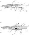
Nach einem ersten Gesichtspunkt der vorliegenden Erfindung wird diese Aufgabe bei der eingangs genannten Haltevorrichtung dadurch gelöst, dass das Implantat für die Beweglichkeit des Pedikelstabes einen Hohlraum aufweist und dass der Pedikelstab in dem Hohlraum für eine permanente Beweglichkeit des Pedikelstabes in Bezug auf das Implantat angeordnet ist. Diese Ausgestaltung weist den Vorteil auf, dass eine dynamische segmentale Stabilisierung mit einem Rotationszentrum im Bereich des physiologischen Drehzentrums ventral von der Pedikelebene erreicht werden kann. Dadurch wird ein weitgehend physiologisches Bewegungsmuster bewirkt. Ein zusätzlicher Vorteil liegt darin, dass ein effektiver Schutz der Anschlussdegeneration und die Erhaltung eines größeren Bewegungsumfanges erreicht werden kann.According to a first aspect of the present invention, this object is achieved in the aforementioned holding device in that the implant for the mobility of the pedicle rod has a cavity and that the pedicle rod is disposed in the cavity for permanent mobility of the pedicle rod with respect to the implant. This embodiment has the advantage that a dynamic segmental stabilization with a center of rotation in the region of the physiological center of rotation can be achieved ventrally from the pedicle plane. This causes a largely physiological movement pattern. An additional advantage is that effective protection of terminal degeneration and preservation of greater range of motion can be achieved.
Als vorteilhaft hat es sich erwiesen, wenn das Implantat eine hülsenförmige Ausgestaltung aufweist, wodurch die Einbringung des Implantates in den Wirbelkörper erleichtert wird.It has proven to be advantageous if the implant has a sleeve-shaped configuration, whereby the introduction of the implant is facilitated in the vertebral body.
Bevorzugt weist der Pedikelstab einen elastischen Bereich auf. Besonders bevorzugt ist der elastische Bereich aus einem Material gebildet, das aus einer Gruppe ausgewählt worden ist, die umfasst: Metalle und insbesondere Titan und dessen Legierungen, Stahl oder CoCr oder Kunststoffe und insbesondere Polyethylen, Polyurethan, Polyetheretherketon, kohlenstofffaserverstärkten Kunststoff oder superelastischen Nitinol. Diese Ausgestaltung weist den Vorteil auf, dass die Beweglichkeit des Pedikelstabes zu dem Implantat einfach bewirkt werden kann.The pedicle rod preferably has an elastic region. More preferably, the elastic region is formed from a material selected from a group comprising: metals and in particular titanium and its alloys, steel or CoCr or plastics and in particular polyethylene, polyurethane, polyetheretherketone, carbon fiber reinforced plastic or superelastic nitinol. This embodiment has the advantage that the mobility of the pedicle rod to the implant can be easily effected.
Weiterhin kann das Implantat ein elastisches Element aufweisen, das an einem Verbindungsbereich zwischen dem Implantat und dem Pedikelstab angeordnet ist. Diese Ausführung weist den Vorteil auf, dass durch die Verwendung eines dämpfenden Elementes eine zusätzliche Stabilisierung erreicht werden kann. Hierfür kann z. B. ein Hohlzylinder aus Polycarbonaturethan (PCU) in dem Hohlraum zwischen Implantat und Pedikelstab angebracht werden, wobei die Form und die Geometrie variiert werden kann, um das Ausmaß der Dämpfung und der Stabilisierung gezielt zu bestimmen.Furthermore, the implant may have an elastic element which is arranged at a connection region between the implant and the pedicle rod. This embodiment has the advantage that an additional stabilization can be achieved by the use of a damping element. For this purpose, z. For example, a hollow cylinder of polycarbonate urethane (PCU) may be placed in the cavity between the implant and pedicle rod, the shape and geometry of which may be varied to selectively determine the extent of damping and stabilization.
Bei einem bevorzugten Ausführungsbeispiel weist das Implantat eine Gewindeverankerung in dem Hohlraum und der Pedikelstab einen Gewindeabschnitt auf, wodurch eine feste, aber lösbare Verbindung zwischen Implantat und Pedikelstab erreicht werden kann. Weiterhin sind auch andere Fügetechniken wie z. B. Kleben, Klemmen, Schweißen, Schnappen oder Rasten möglich.In a preferred embodiment, the implant has a threaded anchor in the lumen and the pedicle rod has a threaded portion whereby a firm but releasable connection between the implant and pedicle rod can be achieved. Furthermore, other joining techniques such. As bonding, clamping, welding, snapping or locking possible.
Außerdem kann eine einachsige, eine zweiachsige oder eine polyaxiale Gelenkverbindung zwischen dem Implantat und dem Pedikelstab vorgesehen sein, wodurch die Beweglichkeit, insbesondere die Flexion und die Extension, des Pedikelstabes zu dem Implantat einfach bewirkt werden kann.In addition, a uniaxial, a biaxial or a polyaxial articulation between the implant and the pedicle rod may be provided, whereby the mobility, in particular the flexion and extension of the pedicle rod to the implant can be easily effected.
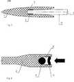
Bei der Haltevorrichtung für Wirbelkörper hat es sich als vorteilhaft erwiesen, wenn in dem posterioren Bereich das Implantat eine Anschlagfläche und der Pedikelstab eine Anschlagsgegenfläche zur Begrenzung der Beweglichkeit zwischen dem Implantat und dem Pedikelstab aufweisen.In the case of the holding device for vertebral bodies, it has proved to be advantageous if, in the posterior region, the implant has a stop surface and the pedicle rod has an abutment counter surface for limiting the mobility between the implant and the pedicle rod.
Bevorzugt weist der Pedikelstab posterior eine sekundär schließbare Stabaufnahme auf. In diesem Zusammenhang hat es sich als besonders günstig erwiesen, wenn die Stabaufnahme ein verstellbares Sperrelement umfasst. Diese Ausgestaltung weist den Vorteil auf, dass die Herstellung einer winkelstabilen Verbindung sekundär über einen perkutanen Eingriff möglich wird und z. B. bei kritischen Knochenverhältnissen ein Einwachsen der Implantate ohne Belastung ermöglicht wird. Wenn das Einwachsen erfolgt ist, kann z. B. perkutan in Lokalanästhesie die dorsale Verbindung geschlossen werden, wodurch die dynamische oder auch rigide segmentale Stabilisierung aktiviert wird.The pedicle rod preferably has a secondarily closable rod receptacle in the posterior direction. In this context, it has proven to be particularly advantageous if the rod holder comprises an adjustable blocking element. This embodiment has the advantage that the production of a stable-angle connection is possible secondarily via a percutaneous procedure and z. B. in critical bone conditions, an ingrowth of the implants is made possible without load. If the ingrowth is done, z. B. percutaneously closed in local anesthesia dorsal connection, whereby the dynamic or rigid segmental stabilization is activated.
Bei einer Haltevorrichtung für Wirbelkörper nach der vorliegenden Erfindung ist es vorteilhaft, wenn der Pedikelstab einen ovalen Querschnitt aufweist. Durch den ovalen Querschnitt kann der Bewegungsumfang für Flexionen und/oder Extensionen bei gleichbleibender Stabilität erhöht werden. Aufgrund des ovalen Querschnittes kann das Widerstandsmoment in unterschiedliche Ebenen unterschiedlich groß sein, so dass z. B. die Flexion leichter möglich ist als die Seitbiegung. Weiterhin wird hierdurch die Stabilität bei Rotationen erhöht.In a vertebral body retainer according to the present invention, it is advantageous if the pedicle rod has an oval cross-section. Due to the oval cross section, the range of motion for flexions and / or extensions can be increased while maintaining stability. Due to the oval cross-section, the moment of resistance can be different in different levels, so that z. B. the inflection easier possible as the lateral bend. Furthermore, this increases the stability during rotations.
Besonders vorteilhaft ist es, wenn das Implantat mit einer posterior abnehmenden Wandstärke ausgebildet ist.It is particularly advantageous if the implant is designed with a posteriorly decreasing wall thickness.
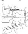
Bevorzugt weist bei der Haltevorrichtung für Wirbelkörper das Implantat posterior auf einer Seite einen Verlängerungsabschnitt auf, der für eine dauerhafte Anbringung eines mit einer zweiten Haltevorrichtung verbundenen Verbindungselements mit einem Kopplungsmittel, insbesondere mit einer Verbindungselementaufnahme ausgestaltet ist. Diese Ausgestaltung ist für mehrsegmentale dynamische Anwendungen besonders geeignet. Zum Erreichen einer vollen Dynamik, insbesondere bei Flexion/Extension, über mehrere Segmente ist es erforderlich, die hierbei im Bereich der dorsalen Verbindungselemente auftretenden Längenänderungen zu kompensieren, so dass sich die Beweglichkeiten der einzelnen Segmente summieren können. Die Verbindung zwischen den einzelnen dynamischen Haltevorrichtungen erfolgt so, dass jeweils der Pedikelstab der einen Haltevorrichtung mit dem nächst kranialeren Implantat (Hülse) an dem Verlängerungsabschnitt über das Kopplungsmittel verbunden wird. Dadurch kann eine beliebig lange Stabilisierung erreicht werden. Dieser Vorteil kann nach der vorliegenden Erfindung für ein dorsales Fixationssystem mit einer Anzahl an derartigen Haltevorrichtungen dadurch erreicht werden, dass mindestens die erste Haltevorrichtung ein Verbindungselement aufweist, das über ein Befestigungsteil der ersten Haltevorrichtung mit dem Pedikelstab der ersten Haltevorrichtung und über das Kopplungsmittel der zweiten Haltevorrichtung mit der zweiten Haltevorrichtung verbunden ist.Preferably, in the vertebral body retainer, the implant has an extension portion posteriorly on one side which is configured for permanent attachment of a connector connected to a second retainer to a coupling means, in particular to a connector retainer. This embodiment is particularly suitable for multi-segment dynamic applications. In order to achieve full dynamics, in particular in the case of flexion / extension, over several segments, it is necessary to compensate for the length changes which occur in the area of the dorsal connecting elements, so that the movabilities of the individual segments can add up. The connection between the individual dynamic holding devices is such that in each case the pedicle rod of a holding device with the next cranial implant (sleeve) is connected to the extension portion via the coupling means. This allows an arbitrarily long stabilization can be achieved. This advantage can be achieved according to the present invention for a dorsal fixation system with a number of such holding devices, characterized in that at least the first holding device comprises a connecting element via a fixing part of the first holding device with the pedicle bar of the first holding device and the coupling means of the second holding device is connected to the second holding device.
Nach einem zweiten Gesichtspunkt der vorliegenden Erfindung wird diese Aufgabe bei einem dorsalem Fixationssystem dadurch gelöst, dass eine erste Haltevorrichtung für Wirbelkörper nach einem der oben genannten Ausführungsbeispiele und eine zweite Haltevorrichtung für Wirbelkörper mit einem Verbindungselement vorgesehen ist, das ein erstes Befestigungsteil mit dem ersten Pedikelstab der ersten Haltevorrichtung und ein zweites Befestigungsteil mit dem zweiten Pedikelstab der zweiten Haltevorrichtung aufweist. Diese Ausgestaltung weist den Vorteil auf, dass durch das physiologischer platzierte Drehzentrum im dorsalen Anteil des Wirbelkörpers eine bessere Segmentbeweglichkeit bewirkt wird. Dadurch kann das System z. B. auch als eine Bandscheibenprothese verwendet werden. Darüber hinaus ist in einem späteren Stadium auch eine Kombination mit einem Facettengelenkersatz möglich.According to a second aspect of the present invention, this object is achieved in a dorsal fixation system in that a first holding device for vertebral bodies according to one of the above embodiments and a second holding device for vertebral bodies is provided with a connecting element having a first attachment part with the first Pedikelstab the Having the first holding device and a second fastening part with the second pedicle rod of the second holding device. This embodiment has the advantage that a better segment mobility is effected by the physiologically placed center of rotation in the dorsal portion of the vertebral body. This allows the system z. B. also be used as a disc prosthesis. In addition, a combination with a facet joint replacement is possible at a later stage.
Bevorzugt sind bei dem dorsalen Fixationssystem das erste Befestigungsteil und/oder das zweite Befestigungsteil ausgestaltet, einen ersten Winkel zwischen dem Verbindungselement und dem ersten Pedikelstab der ersten Haltevorrichtung bzw. einen zweiten Winkel zwischen dem Verbindungselement und dem zweiten Pedikelstab der zweiten Haltevorrichtung stabil zu halten.Preferably, in the dorsal fixation system, the first attachment member and / or the second attachment member are configured to stably maintain a first angle between the connector and the first pedicle rod of the first holder and a second angle between the connector and the second pedicle rod of the second holder.
Alternativ kann bei dem dorsalen Fixationssystem das erste Befestigungsteil und/oder das zweite Befestigungsteil ausgestaltet sein, einen ersten Winkel zwischen dem Verbindungselement und dem ersten Pedikelstab der ersten Haltevorrichtung bzw. einen zweiten Winkel zwischen dem Verbindungselement und dem zweiten Pedikelstab der zweiten Haltevorrichtung variabel zu halten.Alternatively, in the dorsal fixation system, the first attachment member and / or the second attachment member may be configured to variably hold a first angle between the connector and the first pedicle rod of the first holder and a second angle between the connector and the second pedicle rod of the second holder.
Bei dem dorsalen Fixationssystem hat es sich als vorteilhaft erwiesen, wenn das Verbindungselement einen teleskopischen Bereich und/oder einen flexiblen Bereich aufweist, um die im Bereich der dorsalen Verbindungselemente auftretenden Längenänderungen zu kompensieren.In the case of the dorsal fixation system, it has proved to be advantageous if the connecting element has a telescopic area and / or a flexible area in order to compensate for the length changes occurring in the region of the dorsal connecting elements.
Bevorzugt weist das dorsale Fixationssystem eine dritte Haltevorrichtung für Wirbelkörper auf und ist das Verbindungselement über ein drittes Befestigungsteil an der dritten Haltevorrichtung mit einem dritten Pedikelstab der dritten Haltevorrichtung verbunden ist. Auf diese Weise kann eine mehrsegmentale dynamische Stabilisierung erreicht werden.The dorsal fixation system preferably has a third holding device for vertebral bodies, and the connecting element is connected to a third pedicle rod of the third holding device via a third fastening part on the third holding device. In this way, a multi-segment dynamic stabilization can be achieved.
Ein weiterer Vorteil des erfindungsgemäßen Fixationssystems liegt darin, dass über das dorsale Verbindungselement eine Segmentdistraktion möglich ist, um z. B. die Bandscheibe kontinuierlich zu entlasten.Another advantage of the fixation system according to the invention is that a segment distraction is possible via the dorsal connecting element in order, for. B. continuously relieve the intervertebral disc.
Im Folgenden wird die Erfindung an in den Zeichnungen dargestellten Ausführungsbeispielen näher erläutert; es zeigen:In the following the invention is explained in more detail in exemplary embodiments illustrated in the drawings; show it:
Der Pedikelstab
Um das Ausmaß der Dynamik und das Drehzentrum besser an patientenspezifische Anforderungen anpassen zu können, kann der Pedikelstab
Durch unterschiedliche Ausgestaltungen des dynamischen Bereiches kann somit eine optimale Adaption an die speziellen Bedürfnisse der jeweiligen Patienten erfolgen. Weiterhin kann ein rigider Pedikelstab in dem System enthalten sein, um einen sekundären Wechsel von einer dynamischen Stabilisierung zu einer rigiden Stabilisierung zu ermöglichen oder um einen sekundären Wechsel von einer rigiden Stabilisierung zu einer dynamischen Stabilisierung zu ermöglichen.By means of different embodiments of the dynamic range, an optimal adaptation to the special needs of the respective patients can thus take place. Furthermore, a rigid pedicle rod may be included in the system to allow for secondary change from dynamic stabilization to rigid stabilization or to allow a secondary change from rigid stabilization to dynamic stabilization.
Zum besseren Verständnis der vorliegenden Erfindung ist in der
Weiterhin weist bei dem in der
Weiterhin ist es bei dem dorsalen Fixationssystem nach der vorliegenden Erfindung die Anzahl der Haltevorrichtungen für Wirbelkörper der Wirbelsäule nicht auf zwei begrenzt, sondern es können auch mehr Haltevorrichtungen eingesetzt werden.Further, in the dorsal fixation system according to the present invention, the number of spinal vertebral body retainers is not limited to two, but more retainer devices may be used.
In der
BezugszeichenlisteLIST OF REFERENCE NUMBERS
- 11
- Implantatimplant
- 1a1a
- erstes Implantatfirst implant
- 1b1b
- zweites Implantatsecond implant
- 1c1c
- drittes Implantatthird implant
- 22
- PedikelstabPedikelstab
- 2a2a
- erster Pedikelstabfirst pedicle stick
- 2b2 B
- zweiter Pedikelstabsecond pedicle rod
- 2c2c
- dritter Pedikelstabthird pedicle rod
- 33
- Hohlraumcavity
- 44
- Gewindeverankerung im ImplantatThread anchoring in the implant
- 55
- Gewindeabschnitt des PedikelstabesThread section of the pedicle rod
- 66
- Anschlagfläche des ImplantatesStop surface of the implant
- 77
- Anschlagsgegenfläche des PedikelstabesAbutment surface of the pedicle rod
- 88th
- schließbare Stabaufnahmelockable rod holder
- 99
- Sperrelementblocking element
- 1010
- elastisches Elementelastic element
- 1111
- Verbindungselementconnecting element
- 11a11a
- erstes Verbindungselementfirst connecting element
- 11b11b
- zweites Verbindungselementsecond connecting element
- 11c11c
- drittes Verbindungselementthird connecting element
- 1212
- dynamischer Bereichdynamic range
- 1313
- BewegungslimitierungsbereichRLD area
- 1414
- Verankerungsbereichanchoring area
- 15a15a
- erstes Befestigungsteilfirst fastening part
- 15b15b
- zweites Befestigungsteilsecond fastening part
- 15c15c
- drittes Befestigungsteilthird fastening part
- 16a16a
- erstes mechanisches Drehzentrumfirst mechanical turning center
- 16b16b
- zweites mechanisches Drehzentrumsecond mechanical turning center
- 16c16c
- drittes mechanisches Drehzentrumthird mechanical turning center
- 17a17a
- erster posteriorer Verlängerungsabschnittfirst posterior extension section
- 17b17b
- zweiter posteriorer Verlängerungsabschnittsecond posterior extension section
- 17c17c
- dritter posteriorer Verlängerungsabschnittthird posterior extension section
- 1818
- Kopplungsmittelcoupling agent
- 1919
- teleskopischer Bereich des Verbindungselementestelescopic area of the connecting element
- 20a20a
- Haltevorrichtung nach erstem AusführungsbeispielHolding device according to the first embodiment
- 20b20b
- Haltevorrichtung nach zweitem AusführungsbeispielHolding device according to the second embodiment
- 20c20c
- Haltevorrichtung nach drittem AusführungsbeispielHolding device according to the third embodiment
- 20d20d
- Haltevorrichtung nach viertem AusführungsbeispielHolding device according to the fourth embodiment
- 2121
- erste Haltevorrichtungfirst holding device
- 2222
- zweite Haltevorrichtungsecond holding device
- 2323
- dritte Haltevorrichtungthird holding device
- 3131
- physiologisches Drehzentrumphysiological center of rotation
- 3030
- flexibler Bereich des Verbindungselementesflexible area of the connecting element
- 31a31a
- erstes physiologisches Drehzentrumfirst physiological center of rotation
- 31b31b
- zweites physiologisches Drehzentrumsecond physiological center of rotation
- 31c31c
- drittes physiologisches Drehzentrumthird physiological center of rotation
- 50a50a
- dorsales Fixationssystem nach einem ersten Ausführungsbeispieldorsal fixation system according to a first embodiment
- 50b50b
- dorsales Fixationssystem nach einem zweiten Ausführungsbeispieldorsal fixation system according to a second embodiment
- 50c50c
- dorsales Fixationssystem nach einem dritten Ausführungsbeispieldorsal fixation system according to a third embodiment
- 50d50d
- dorsales Fixationssystem nach einem vierten Ausführungsbeispieldorsal fixation system according to a fourth embodiment
- 50e50e
- dorsales Fixationssystem nach einem fünften Ausführungsbeispieldorsal fixation system according to a fifth embodiment
- 50f50f
- dorsales Fixationssystem nach einem sechsten Ausführungsbeispieldorsal fixation system according to a sixth embodiment
- 200200
- herkömmliche Haltevorrichtungconventional holding device
- αα
- erster Winkel zwischen dem Verbindungselement und dem ersten Pedikelstabfirst angle between the connecting element and the first Pedikelstab
- ββ
- zweiter Winkel zwischen dem Verbindungselement und dem zweiten Pedikelstabsecond angle between the connecting element and the second Pedikelstab
Claims (19)
Translated fromGermanPriority Applications (10)
| Application Number | Priority Date | Filing Date | Title |
|---|---|---|---|
| DE201010016854DE102010016854A1 (en) | 2010-05-10 | 2010-05-10 | Retaining device for vertebral bodies of the spine |
| US12/869,977US9119671B2 (en) | 2010-05-10 | 2010-08-27 | Fixation assembly for spinal vertebrae |
| TW100108209ATWI544895B (en) | 2010-05-10 | 2011-03-11 | Fixation assembly for spinal vertebrae |
| EP11161088.7AEP2386258B1 (en) | 2010-05-10 | 2011-04-05 | Holding device for spine vertebrae |
| ES11161088.7TES2584037T3 (en) | 2010-05-10 | 2011-04-05 | Retention device for vertebral bodies of the spine |
| MX2011004699AMX2011004699A (en) | 2010-05-10 | 2011-05-04 | Holding device for spine vertebrae. |
| RU2011118235/14ARU2549529C2 (en) | 2010-05-10 | 2011-05-05 | Fixing device for body of vertebral column vertebra |
| BRPI1102461-5ABRPI1102461A2 (en) | 2010-05-10 | 2011-05-10 | spinal body fixation device |
| JP2011105558AJP5705017B2 (en) | 2010-05-10 | 2011-05-10 | Retention brace for spine vertebral body |
| CN201110131406.XACN102240222B (en) | 2010-05-10 | 2011-05-10 | Holding means for spinal vertebral |
Applications Claiming Priority (1)
| Application Number | Priority Date | Filing Date | Title |
|---|---|---|---|
| DE201010016854DE102010016854A1 (en) | 2010-05-10 | 2010-05-10 | Retaining device for vertebral bodies of the spine |
Publications (1)
| Publication Number | Publication Date |
|---|---|
| DE102010016854A1true DE102010016854A1 (en) | 2011-11-10 |
Family
ID=44315006
Family Applications (1)
| Application Number | Title | Priority Date | Filing Date |
|---|---|---|---|
| DE201010016854WithdrawnDE102010016854A1 (en) | 2010-05-10 | 2010-05-10 | Retaining device for vertebral bodies of the spine |
Country Status (10)
| Country | Link |
|---|---|
| US (1) | US9119671B2 (en) |
| EP (1) | EP2386258B1 (en) |
| JP (1) | JP5705017B2 (en) |
| CN (1) | CN102240222B (en) |
| BR (1) | BRPI1102461A2 (en) |
| DE (1) | DE102010016854A1 (en) |
| ES (1) | ES2584037T3 (en) |
| MX (1) | MX2011004699A (en) |
| RU (1) | RU2549529C2 (en) |
| TW (1) | TWI544895B (en) |
Families Citing this family (14)
| Publication number | Priority date | Publication date | Assignee | Title |
|---|---|---|---|---|
| EP2740427B1 (en) | 2012-12-05 | 2020-03-11 | Biedermann Technologies GmbH & Co. KG | Dynamic bone anchor and method of manufacturing the same |
| FR3010628B1 (en) | 2013-09-18 | 2015-10-16 | Medicrea International | METHOD FOR REALIZING THE IDEAL CURVATURE OF A ROD OF A VERTEBRAL OSTEOSYNTHESIS EQUIPMENT FOR STRENGTHENING THE VERTEBRAL COLUMN OF A PATIENT |
| FR3012030B1 (en) | 2013-10-18 | 2015-12-25 | Medicrea International | METHOD FOR REALIZING THE IDEAL CURVATURE OF A ROD OF A VERTEBRAL OSTEOSYNTHESIS EQUIPMENT FOR STRENGTHENING THE VERTEBRAL COLUMN OF A PATIENT |
| US10456211B2 (en) | 2015-11-04 | 2019-10-29 | Medicrea International | Methods and apparatus for spinal reconstructive surgery and measuring spinal length and intervertebral spacing, tension and rotation |
| EP3376987B1 (en)* | 2015-11-19 | 2020-10-28 | EOS Imaging | Method of preoperative planning to correct spine misalignment of a patient |
| WO2018109556A1 (en) | 2016-12-12 | 2018-06-21 | Medicrea International | Systems and methods for patient-specific spinal implants |
| EP3612122B1 (en) | 2017-04-21 | 2023-12-20 | Medicrea International | A system for developing one or more patient-specific spinal implants |
| US10918422B2 (en) | 2017-12-01 | 2021-02-16 | Medicrea International | Method and apparatus for inhibiting proximal junctional failure |
| TWI677056B (en) | 2018-04-16 | 2019-11-11 | 華邦電子股份有限公司 | Semiconductor devices and methods for manufacturing the same |
| US11925417B2 (en) | 2019-04-02 | 2024-03-12 | Medicrea International | Systems, methods, and devices for developing patient-specific spinal implants, treatments, operations, and/or procedures |
| US11944385B2 (en) | 2019-04-02 | 2024-04-02 | Medicrea International | Systems and methods for medical image analysis |
| US11877801B2 (en) | 2019-04-02 | 2024-01-23 | Medicrea International | Systems, methods, and devices for developing patient-specific spinal implants, treatments, operations, and/or procedures |
| US11769251B2 (en) | 2019-12-26 | 2023-09-26 | Medicrea International | Systems and methods for medical image analysis |
| US12318144B2 (en) | 2021-06-23 | 2025-06-03 | Medicrea International SA | Systems and methods for planning a patient-specific spinal correction |
Family Cites Families (15)
| Publication number | Priority date | Publication date | Assignee | Title |
|---|---|---|---|---|
| FR2694182B1 (en) | 1992-07-31 | 1994-10-21 | Psi | Attachment for prosthesis, especially interpedicular. |
| US6273914B1 (en) | 1995-09-28 | 2001-08-14 | Sparta, Inc. | Spinal implant |
| RU2218122C1 (en)* | 2002-03-21 | 2003-12-10 | Научно-исследовательский центр Татарстана "Восстановительная травматология и ортопедия" | Device for treating posterior spondylodesis |
| US20050171543A1 (en)* | 2003-05-02 | 2005-08-04 | Timm Jens P. | Spine stabilization systems and associated devices, assemblies and methods |
| CA2524145A1 (en) | 2003-05-02 | 2004-11-18 | Yale University | Dynamic spine stabilizer |
| DE10348329B3 (en) | 2003-10-17 | 2005-02-17 | Biedermann Motech Gmbh | Rod-shaped element used in spinal column and accident surgery for connecting two bone-anchoring elements comprises a rigid section and an elastic section that are made in one piece |
| US20050085814A1 (en)* | 2003-10-21 | 2005-04-21 | Sherman Michael C. | Dynamizable orthopedic implants and their use in treating bone defects |
| US8632570B2 (en)* | 2003-11-07 | 2014-01-21 | Biedermann Technologies Gmbh & Co. Kg | Stabilization device for bones comprising a spring element and manufacturing method for said spring element |
| RU2321371C1 (en)* | 2006-07-14 | 2008-04-10 | Научно-исследовательский центр Татарстана "Восстановительная травматология и ортопедия" | Reposition spinal column lock |
| US8048128B2 (en) | 2007-06-05 | 2011-11-01 | Spartek Medical, Inc. | Revision system and method for a dynamic stabilization and motion preservation spinal implantation system and method |
| US8052722B2 (en) | 2007-06-05 | 2011-11-08 | Spartek Medical, Inc. | Dual deflection rod system for a dynamic stabilization and motion preservation spinal implantation system and method |
| US8048115B2 (en)* | 2007-06-05 | 2011-11-01 | Spartek Medical, Inc. | Surgical tool and method for implantation of a dynamic bone anchor |
| US8048123B2 (en)* | 2007-06-05 | 2011-11-01 | Spartek Medical, Inc. | Spine implant with a deflection rod system and connecting linkages and method |
| FR2924014B1 (en)* | 2007-11-22 | 2010-01-22 | Henry Graf | DEVICE FOR CONNECTING AT LEAST THREE VERTEBRATES BETWEEN THEM |
| US8057517B2 (en)* | 2008-02-26 | 2011-11-15 | Spartek Medical, Inc. | Load-sharing component having a deflectable post and centering spring and method for dynamic stabilization of the spine |
- 2010
- 2010-05-10DEDE201010016854patent/DE102010016854A1/ennot_activeWithdrawn
- 2010-08-27USUS12/869,977patent/US9119671B2/ennot_activeExpired - Fee Related
- 2011
- 2011-03-11TWTW100108209Apatent/TWI544895B/ennot_activeIP Right Cessation
- 2011-04-05EPEP11161088.7Apatent/EP2386258B1/ennot_activeNot-in-force
- 2011-04-05ESES11161088.7Tpatent/ES2584037T3/enactiveActive
- 2011-05-04MXMX2011004699Apatent/MX2011004699A/enactiveIP Right Grant
- 2011-05-05RURU2011118235/14Apatent/RU2549529C2/ennot_activeIP Right Cessation
- 2011-05-10JPJP2011105558Apatent/JP5705017B2/ennot_activeExpired - Fee Related
- 2011-05-10CNCN201110131406.XApatent/CN102240222B/ennot_activeExpired - Fee Related
- 2011-05-10BRBRPI1102461-5Apatent/BRPI1102461A2/ennot_activeIP Right Cessation
Also Published As
| Publication number | Publication date |
|---|---|
| BRPI1102461A2 (en) | 2012-10-16 |
| JP5705017B2 (en) | 2015-04-22 |
| MX2011004699A (en) | 2011-11-18 |
| CN102240222B (en) | 2016-11-16 |
| CN102240222A (en) | 2011-11-16 |
| RU2549529C2 (en) | 2015-04-27 |
| ES2584037T3 (en) | 2016-09-23 |
| EP2386258A1 (en) | 2011-11-16 |
| US9119671B2 (en) | 2015-09-01 |
| EP2386258B1 (en) | 2016-06-22 |
| TW201138711A (en) | 2011-11-16 |
| TWI544895B (en) | 2016-08-11 |
| US20110276094A1 (en) | 2011-11-10 |
| RU2011118235A (en) | 2012-11-10 |
| JP2011235104A (en) | 2011-11-24 |
Similar Documents
| Publication | Publication Date | Title |
|---|---|---|
| EP2386258B1 (en) | Holding device for spine vertebrae | |
| DE102004048938B4 (en) | Device for the dynamic stabilization of vertebral bodies | |
| DE60203159T2 (en) | Spinal implant inserted between vertebral spinous processes | |
| DE69919912T2 (en) | Arrangement for stabilizing two adjacent vertebrae of the spine | |
| DE60210502T2 (en) | BONE IMPLANT WITH POLYAXIAL HEAD | |
| DE60124871T2 (en) | SYSTEM FOR SUPERELASTIC STABILIZATION OF THE BACKGRATE | |
| EP1570795B1 (en) | Apparatus for dynamic stabilisation of the spine or bones and rod-like element for same | |
| EP2226039B1 (en) | Implant for the thoracic and lumbar spine | |
| EP0792127B1 (en) | Joint prosthesis | |
| DE10324319A1 (en) | Implant and instrument for placement and distraction of the implant | |
| WO2004110287A1 (en) | Device for dynamically stabilizing bones or bone fragments, especially thoracic vertebral bodies | |
| EP2457541A1 (en) | Implant between vertebrae | |
| EP2645950B1 (en) | Fusion implant for facet joints | |
| DE202005020876U1 (en) | Endoprosthesis comprises a shaft, which extends along a primary axis, a distal end piece and a proximal end piece | |
| EP2116211A1 (en) | Intervertebral prosthesis | |
| EP2460492B1 (en) | Wrist prosthesis | |
| DE102012203256A1 (en) | Implant structure for supporting spine in inter vertebral space, has anterior support element and posterior support element that are connected with adjusting mechanism where support elements are spaced apart at a distance | |
| EP2505156B1 (en) | Facet joint implant | |
| DE20115281U1 (en) | Implant | |
| DE102010041264A1 (en) | Dynamic stabilization device for the spine | |
| DE102012202749A1 (en) | Dynamic stabilization device for bone e.g. spinal column, has deformable regions that are arranged in form of loop, so that sides of loop surround bone in bone quiescent state | |
| DE102019005374A1 (en) | SPINE IMPLANT CONNECTION DEVICE | |
| DE102014000293B4 (en) | Surgical implant for the stabilization of the spine and the trunk for use in human medicine | |
| DE102010040236A1 (en) | Dynamic stabilization device for joints or spinal column segments, having head region that is connected to fixing block via joint kinematics | |
| WO2008141633A2 (en) | Intervertebral prosthesis, and instrument combination comprising an intervertebral prosthesis |
Legal Events
| Date | Code | Title | Description |
|---|---|---|---|
| R016 | Response to examination communication | ||
| R119 | Application deemed withdrawn, or ip right lapsed, due to non-payment of renewal fee |