Movatterモバイル変換


[0]ホーム

URL:


DE102010016818A1 - Method and apparatus for performing multipoint FCS - Google Patents

Method and apparatus for performing multipoint FCS
Download PDF

Info

Publication number
DE102010016818A1
DE102010016818A1DE102010016818ADE102010016818ADE102010016818A1DE 102010016818 A1DE102010016818 A1DE 102010016818A1DE 102010016818 ADE102010016818 ADE 102010016818ADE 102010016818 ADE102010016818 ADE 102010016818ADE 102010016818 A1DE102010016818 A1DE 102010016818A1
Authority
DE
Germany
Prior art keywords
sample
illumination
dye particles
detector
light beam
Prior art date
Legal status (The legal status is an assumption and is not a legal conclusion. Google has not performed a legal analysis and makes no representation as to the accuracy of the status listed.)
Withdrawn
Application number
DE102010016818A
Other languages
German (de)
Inventor
Dr. Knebel Werner
Current Assignee (The listed assignees may be inaccurate. Google has not performed a legal analysis and makes no representation or warranty as to the accuracy of the list.)
Leica Microsystems CMS GmbH
Original Assignee
Leica Microsystems CMS GmbH
Priority date (The priority date is an assumption and is not a legal conclusion. Google has not performed a legal analysis and makes no representation as to the accuracy of the date listed.)
Filing date
Publication date
Application filed by Leica Microsystems CMS GmbHfiledCriticalLeica Microsystems CMS GmbH
Priority to DE102010016818ApriorityCriticalpatent/DE102010016818A1/en
Priority to US13/048,068prioritypatent/US20110226963A1/en
Priority to EP11158204Aprioritypatent/EP2366990A3/en
Publication of DE102010016818A1publicationCriticalpatent/DE102010016818A1/en
Withdrawnlegal-statusCriticalCurrent

Links

Images

Classifications

Landscapes

Abstract

Translated fromGerman

Zur Durchführung einer Fluoreszenz-Korrelations-Spektroskopie mit einem Fluoreszenz-Mikroskop (29) wird ein Bild einer Probe (40) aufgenommen. Anhand des Bildes wird mindestens ein zu untersuchender Beleuchtungsbereich (43) der Probe (40) ausgewählt. Zu jedem ausgewählten Beleuchtungsbereich (43) wird mindestens ein Beleuchtungsfokus (42) eines Beleuchtungslichtstrahls (24) in dem entsprechenden Beleuchtungsbereich (43) der Probe (40) erzeugt, wodurch fluoreszierende Farbstoffpartikel, die mit Probenmolekülen der Probe (40) gekoppelt sind, innerhalb des entsprechenden Beleuchtungsbereichs (43) zum Fluoreszieren angeregt werden. Das von den Farbstoffpartikeln emittierte Fluoreszenzlicht (44) wird detektiert und abhängig von dem detektierten Fluoreszenzlicht (44) wird mindestens ein Diffusionskoeffizient ermittelt, der repräsentativ für eine Diffusionsfähigkeit der fluoreszierenden Farbstoffpartikel und der mit den Farbstoffpartikeln gekoppelten Probenmolekülen ist.To carry out fluorescence correlation spectroscopy with a fluorescence microscope (29), an image of a sample (40) is recorded. At least one illumination area (43) of the sample (40) to be examined is selected on the basis of the image. For each selected illumination area (43), at least one illumination focus (42) of an illumination light beam (24) is generated in the corresponding illumination area (43) of the sample (40), as a result of which fluorescent dye particles, which are coupled to sample molecules of the sample (40), within the corresponding lighting area (43) can be excited to fluoresce. The fluorescent light (44) emitted by the dye particles is detected and, depending on the detected fluorescent light (44), at least one diffusion coefficient is determined, which is representative of a diffusibility of the fluorescent dye particles and of the sample molecules coupled to the dye particles.

Description

Translated fromGerman

Die Erfindung betrifft ein Verfahren zur Durchführung von Fluoreszenz-Korrelations-Spektroskopie mit einem Fluoreszenzmikroskop. Ferner betrifft die Erfindung eine Vorrichtung zur Durchführung von Fluoreszenz-Korrelations-Spektroskopie, die ein Fluoreszenzmikroskop umfasst.The invention relates to a method for performing fluorescence correlation spectroscopy with a fluorescence microscope. Furthermore, the invention relates to a device for performing fluorescence correlation spectroscopy, which comprises a fluorescence microscope.

Die Fluoreszenz-Korrelations-Spektroskopie (fluorescence correlation spectroscopy, FCS) ist eine optische Messmethode, mit der Diffusionskoeffizienten und Konzentrationen von Probenmolekülen einer Probe und Interaktionen zwischen den Probenmolekülen gemessen werden (siehe„Two-Focus Fluorescene Correlation Spectroscopy, Dissertation von Thomas Dertinger an der Universität Köln, 2007). Dazu werden fluoreszierende Farbstoffe in die Probe so eingebracht, dass die Farbstoffpartikel mit den Probenmolekülen Verbindungen eingehen. Insbesondere können fluoreszierende Proteine durch Fusion mit Proteinen einer Zelle der Probe diese Proteine der Zelle markieren. Zur Herstellung derartiger Fusionsproteine wird die DNA des zu untersuchenden Proteins mit der DNA des fluoreszierenden Proteins verbunden und in eine Form gebracht, die von der Zelle aufgenommen werden kann, so dass sie das Fusionsprotein selbstständig herstellt. In vielen Anwendungs-Fällen wird das zu untersuchend Protein noch an die korrekte Stelle in der Zelle transportiert. Das fluoreszierende Protein kann mit Hilfe der Fluoreszenzmikroskopie Aufschluss über die zeitliche und räumliche Lokalisation des Zielproteins in der Zelle geben. Als fluoreszierende Proteine sind beispielhaft GFP, PA-GFP, Kaede, Kindling, Dronpa oder PS-CFP genannt.Fluorescence correlation spectroscopy (FCS) is an optical measurement method used to measure the diffusion coefficients and concentrations of sample molecules in a sample and interactions between sample molecules (see "Two-Focus Fluorescene Correlation Spectroscopy, Dissertation by Thomas Dertinger at the University of Cologne, 2007 ). For this purpose, fluorescent dyes are introduced into the sample so that the dye particles enter into compounds with the sample molecules. In particular, fluorescent proteins can label these proteins of the cell by fusion with proteins of a cell of the sample. To prepare such fusion proteins, the DNA of the protein to be examined is linked to the DNA of the fluorescent protein and brought into a form which can be taken up by the cell so that it independently produces the fusion protein. In many cases of application, the protein to be examined is still transported to the correct location in the cell. The fluorescent protein can provide information on the temporal and spatial localization of the target protein in the cell by means of fluorescence microscopy. Examples of fluorescent proteins are GFP, PA-GFP, Kaede, Kindling, Dronpa or PS-CFP.

Durch die Fluoreszenz des fluoreszierenden Proteins kann die räumliche und zeitliche Verteilung des anderen Proteins in lebenden Zellen, Geweben oder Organismen direkt beobachtet werden. Dies ermöglicht das Ermitteln des Diffusionskoeffizienten der fluoreszierenden Farbstoffpartikel und damit die Diffusionsfähigkeit der an die fluoreszierenden Farbstoffpartikel gebundenen Proteine und Probenmoleküle. Darüber hinaus ist es möglich, die Konzentration der an die fluoreszierenden Farbstoffpartikel gebundenen Probenmoleküle zu ermitteln. Anhand der Diffusionskoeffizienten kann dann überprüft werden, ob die Probenmoleküle miteinander interagieren, da sich die Diffusionsfähigkeit der Probenmoleküle bei einer Interaktion verringert. Ähnliche Mikroskopieverfahren, bei denen zum Ermitteln von Diffusionskoeffizienten ein Scan-Mikroskop verwendet wird sind beispielsweise ICS oder RICS.The fluorescence of the fluorescent protein allows direct observation of the spatial and temporal distribution of the other protein in living cells, tissues or organisms. This makes it possible to determine the diffusion coefficient of the fluorescent dye particles and thus the diffusibility of the proteins and sample molecules bound to the fluorescent dye particles. In addition, it is possible to determine the concentration of the sample molecules bound to the fluorescent dye particles. The diffusion coefficients can then be used to check whether the sample molecules interact with one another, since the diffusion capacity of the sample molecules decreases during an interaction. Similar microscopy methods in which a scanning microscope is used to determine diffusion coefficients are, for example, ICS or RICS.

Es ist Aufgabe der Erfindung, ein Verfahren und eine Vorrichtung zur Durchführung einer Fluoreszenz-Korrelations-Spektroskopie zu schaffen, das bzw. die auf einfache und flexible Weise ein Untersuchen einer Probe, insbesondere ein Ermitteln von Diffusionskoeffizienten von Probenmolekülen der Probe, ermöglicht.It is the object of the invention to provide a method and a device for carrying out a fluorescence correlation spectroscopy, which enables a simple and flexible examination of a sample, in particular a determination of diffusion coefficients of sample molecules of the sample.

Die Aufgabe wird gelöst durch die Merkmale der unabhängigen Ansprüche. Vorteilhafte Ausgestaltungen sind in den Unteransprüchen angegeben.The object is solved by the features of the independent claims. Advantageous embodiments are specified in the subclaims.

Die Erfindung zeichnet sich gemäß einem ersten Aspekt durch ein Verfahren zur Durchführung einer Fluoreszenz-Korrelations-Spektroskopie mit einem Fluoreszenzmikroskop aus. Dabei wird ein Beleuchtungslichtstrahl erzeugt und es wird mindestens ein Beleuchtungsbereich der Probe ausgewählt. Der Beleuchtungslichtstrahl wird in mindestens drei Teilstrahlen so aufgespaltet, dass die Teilstrahlen über eine Mikroskopoptik des Fluoreszenzmikroskops auf den ausgewählten Beleuchtungsbereich fokussiert werden, wodurch Farbstoffpartikel in dem Beleuchtungsbereich der Probe zum Fluoreszieren angeregt werden. Das von den Farbstoffpartikeln emittierte Fluoreszenzlicht wird detektiert und abhängig von dem detektierten Fluoreszenzlicht wird mindestens ein Diffusionskoeffizient ermittelt, der repräsentativ für eine Diffusionsfähigkeit der fluoreszierenden Farbstoffpartikel ist.The invention is characterized in a first aspect by a method for performing a fluorescence correlation spectroscopy with a fluorescence microscope. In this case, an illumination light beam is generated and at least one illumination region of the sample is selected. The illumination light beam is split into at least three partial beams so that the partial beams are focused on the selected illumination area via a microscope optics of the fluorescence microscope, whereby fluorescent particles are excited in the illumination area of the sample. The fluorescent light emitted by the dye particles is detected and, depending on the detected fluorescent light, at least one diffusion coefficient which is representative of a diffusibility of the fluorescent dye particles is determined.

Das Auswählen des oder der Beleuchtungsbereiche, der bzw. die völlig beliebig ausgestaltet sein können und deren Anzahl beliebig gewählt werden kann, ermöglicht auf einfache Weise ein besonders flexibles Untersuchen der Probe. Insbesondere können gleichzeitig in den unterschiedlichen Beleuchtungsbereichen Diffusionskoeffizienten gleicher oder unterschiedlicher Farbstoffpartikel und damit gleicher oder unterschiedlicher Probenmoleküle ermittelt und miteinander verglichen werden. Das Ermitteln der Diffusionskoeffizienten ermöglicht, detaillierte Informationen darüber zu erhalten, ob und gegebenenfalls welche Probenmoleküle miteinander interagieren, da bei Interaktionen die Diffusionskoeffizienten der beteiligten Probenmoleküle abnehmen. Die Probenmoleküle umfassen auch Proteine der Probe.The selection of the illumination area (s), which can be configured completely arbitrarily and the number of which can be chosen as desired, makes it possible in a simple way to examine the sample in a particularly flexible manner. In particular, diffusion coefficients of identical or different dye particles and thus identical or different sample molecules can be determined and compared with one another simultaneously in the different illumination regions. The determination of the diffusion coefficients makes it possible to obtain detailed information as to whether and, if appropriate, which sample molecules interact with one another, since the diffusion coefficients of the participating sample molecules decrease during interactions. The sample molecules also include proteins of the sample.

Das Ausleuchten des oder der Beleuchtungsbereiche der Probe mit Hilfe von mindestens drei Teilstrahlen trägt besonders wirkungsvoll dazu bei, dass die Beleuchtungsbereiche beliebig gewählt und gleichzeitig vorteilhaft ausgeleuchtet werden können. Das erfindungsgemäße Verfahren kann auch als Multipoint-FCS bezeichnet werden, wodurch zum Ausdruck kommt, dass das Verfahren eine Fluoreszenz-Korrelations-Spektroskopie mit mehreren, insbesondere mindestens drei Beleuchtungsfoki ist.The illumination of the illumination area or areas of the sample with the aid of at least three partial beams contributes particularly effectively to the fact that the illumination areas can be chosen as desired and at the same time advantageously illuminated. The method according to the invention can also be referred to as multipoint FCS, which indicates that the method is a fluorescence correlation spectroscopy with several, in particular at least three, illumination foci.

In einer vorteilhaften Ausgestaltung wird zunächst ein Bild der Probe aufgenommen und auf einer Anzeigeeinheit dargestellt. Anhand des Bildes wird von einem Benutzer mindestens ein beliebiger oder vorgegebener Teilbereich des Bildes ausgewählt. Abhängig von dem bzw. den ausgewählten Teilbereichen wird ermittelt, wie der Beleuchtungslichtstrahl aufgespaltet werden muss, damit die Teilstrahlen des Beleuchtungslichtstrahls auf Beleuchtungsbereiche der Probe fokussiert werden, die zu den Teilbereichen des Bildes der Probe korrespondieren. Anschließend wird der Beleuchtungslichtstrahl entsprechend aufgespaltet und die Probe entsprechend beleuchtet. Das Auswählen beliebiger Teilbereiche anhand des Bildes der Probe ermöglicht ein besonders intuitives und flexibles Untersuchen der Probe.In an advantageous embodiment, an image of the sample is first taken and displayed on a display unit. On the basis of the image, at least one arbitrary or predetermined subregion of the image is provided by a user selected. Depending on the selected partial area (s), it is determined how the illumination light beam has to be split so that the partial beams of the illumination light beam are focused on illumination areas of the sample which correspond to the partial areas of the image of the sample. Subsequently, the illumination light beam is split accordingly and the sample is illuminated accordingly. Selecting any partitions based on the image of the sample allows for a particularly intuitive and flexible examination of the sample.

Das Fluoreszenzlicht wird auf eine Detektorvorrichtung gelenkt, die mehrere Detektorelemente umfasst. Auf einer sensitiven Fläche der Detektorvorrichtung entstehen aufgrund des Fluoreszenzlichts mehrere Detektionsfoki. Abhängig von dem bzw. den ausgewählten Beleuchtungsbereichen auf oder in der Probe werden Positionen der entsprechenden Detektionsfoki auf der sensitiven Fläche der Detektorvorrichtung ermittelt. Nachfolgend werden selektiv genau die Detektorelemente ausgelesen und/oder deren Signale ausgewertet, auf denen die Detektionsfoki positioniert sind. Dies trägt zu einem besonders effektiven und besonders schnellen Ermitteln der Diffusionskoeffizienten und der Konzentrationen bei.The fluorescent light is directed to a detector device comprising a plurality of detector elements. On a sensitive surface of the detector device, a plurality of detection foci arise due to the fluorescent light. Depending on the selected illumination area (s) on or in the sample, positions of the corresponding detection foci on the sensitive area of the detector device are determined. Subsequently, precisely the detector elements are selectively read out and / or their signals are evaluated, on which the detection foci are positioned. This contributes to a particularly effective and particularly rapid determination of the diffusion coefficients and the concentrations.

Die Konfokalität des Fluoreszenzmikroskops kann einfach eingestellt werden, indem die Anzahl der Detektorelemente, die je Detektionsfokus ausgelesen und/oder ausgewertet werden, eingestellt wird. Dadurch wird ausgenutzt, dass die Detektionsfoki eine Lichtverteilung aufweisen, die regelmäßig ihr Maximum in der Mitte des Detektionsfokus hat. Eine maximale Konfokalität kann nun erreicht werden, wenn lediglich eines der Detektorelemente, das vorzugsweise in der Mitte des Detektionsfokus liegt, ausgelesen bzw. ausgewertet wird. Mit zunehmender Anzahl der Detektorelemente pro Detektionsfokus nimmt dann die Konfokalität ab. Dies entspricht einer Lochblende mit variablem Lochdurchmesser. Im Extremfall werden alle Detektorelemente ausgelesen und ausgewertet, was einer Widefield-Aufnahme der Probe entspricht. Die Widefield-Aufnahme kann beispielsweise zum Aufnehmen des Bildes der Probe genutzt werden.The confocality of the fluorescence microscope can be easily adjusted by adjusting the number of detector elements which are read out and / or evaluated per detection focus. This makes use of the fact that the detection foci have a light distribution which regularly has its maximum in the middle of the detection focus. Maximum confocality can now be achieved if only one of the detector elements, which is preferably located in the middle of the detection focus, is read out or evaluated. As the number of detector elements per detection focus increases, confocality decreases. This corresponds to a pinhole with variable hole diameter. In extreme cases, all detector elements are read out and evaluated, which corresponds to a widefield recording of the sample. For example, the widefield recording can be used to capture the image of the sample.

Die Erfindung zeichnet sich gemäß einem zweiten Aspekt durch eine Vorrichtung zur Durchführung der Fluoreszenz-Korrelations-Spektroskopie aus. Die Vorrichtung umfasst das Fluoreszenzmikroskop, das eine Lichtquelle hat, die den Beleuchtungslichtstrahl erzeugt. Der Beleuchtungslichtstrahl ist auf eine erste Spiegelvorrichtung gerichtet, die eine Vielzahl von optischen Elementen aufweist. Eine Steuereinheit ist mit der ersten Spiegelvorrichtung gekoppelt und steuert die optischen Elemente so an, dass die optischen Elemente den Beleuchtungslichtstrahl in mindestens drei Teilstrahlen aufspalten. Eine Mikroskopoptik fokussiert die Teilstrahlen auf die Beleuchtungsbereiche der Probe. Die Teilstrahlen regen die Farbstoffpartikel der Probe zum Fluoreszieren an. Eine Detektorvorrichtung detektiert die von der Probe emittierten Fluoreszenzlichtstrahlen. Die Detektorvorrichtung umfasst mehrere Detektorelemente, wobei die Steuereinheit steuert, welche Detektorelemente ausgelesen und/oder ausgewertet werden.The invention is characterized in a second aspect by an apparatus for performing the fluorescence correlation spectroscopy. The device comprises the fluorescence microscope which has a light source which generates the illumination light beam. The illuminating light beam is directed to a first mirror device having a plurality of optical elements. A control unit is coupled to the first mirror device and controls the optical elements in such a way that the optical elements split the illumination light beam into at least three partial beams. A microscope optics focuses the partial beams on the illumination areas of the sample. The partial beams excite the dye particles of the sample for fluorescence. A detector device detects the fluorescent light rays emitted by the sample. The detector device comprises a plurality of detector elements, wherein the control unit controls which detector elements are read out and / or evaluated.

Bei der Erzeugung mehrerer Beleuchtungsfoki innerhalb eines oder mehrerer Beleuchtungsbereiche kann aufgrund von Überschneidungen unterschiedlicher Beleuchtungslichtkegel oder Detektionslichtkegel ein unerwünschtes Hintergrundsignal erzeugt werden. Eine Reduktion dieses Hintergrundsignals kann bei einem herkömmlichen konfokalen Mikroskop mit einem einzigen Beleuchtungsfokus mit Hilfe einer Lochblende im Detektionsstrahlengang erreicht werden. Bei Multipoint-FCS mit mehreren Beleuchtungsfoki ist zur Reduktion des Hintergrundsignals vorzugweise eine zweite Spiegelvorrichtung angeordnet, auf die von der Probe emittierte Fluoreszenzlichtlichtstrahlen gerichtet sind und über die die Fluoreszenzlichtstrahlen hin zu der Detektorvorrichtung verlaufen. Die zweite Spiegelvorrichtung weist entsprechend der ersten Spiegelvorrichtung eine Vielzahl von optischen Elementen auf. Bevorzugt erfolgt eine Ansteuerung der optischen Elemente der zweiten Spiegelvorrichtung korrespondierend zu der Ansteuerung der optischen Elemente der ersten Spiegelvorrichtung. Die zweite Spiegelvorrichtung kann wie mehrere Lochblenden verwendet werden, wobei sowohl deren Anzahl als auch deren Lochform abhängig von der Ansteuerung der optischen Elemente variabel ist.When generating a plurality of illumination foci within one or more illumination areas, an undesirable background signal can be generated due to overlaps of different illumination light cones or detection light cones. A reduction of this background signal can be achieved in a conventional confocal microscope with a single illumination focus using a pinhole in the detection beam path. In the case of multipoint FCS with a plurality of illumination foci, a second mirror device is preferably arranged to reduce the background signal, to which fluorescent light beams emitted by the sample are directed and over which the fluorescent light beams pass to the detector device. The second mirror device has a plurality of optical elements corresponding to the first mirror device. Preferably, a control of the optical elements of the second mirror device takes place corresponding to the control of the optical elements of the first mirror device. The second mirror device can be used like a plurality of pinhole diaphragms, wherein both their number and their hole shape is variable depending on the control of the optical elements.

Bei fluoreszierenden Proben ist die Emissionswellenlänge des Fluoreszenzlichts grundsätzlich länger als die Anregungswellenlänge. Somit ist auch der auf die zweite Spiegelvorrichtung projizierte Fokus des Fluoreszenzlichts größer als der entsprechende Beleuchtungsfokus in der Probe. Daher ist es vorteilhaft, um kein Licht zu verlieren, die Lochblendengröße vor der Detektorvorrichtung zu vergrößern. Die Vergrößerung der Lochblende kann man bei der zweiten Spiegelvorrichtung erreichen, indem man außen um die aktiven optischen Elemente der zweiten Spiegelvorrichtung herum, die zu den aktiven optischen Elementen der ersten Spiegelvorrichtung korrespondieren, noch weitere optische Elemente der zweiten Spiegelvorrichtung aktiviert. Will man eine geringe Konfokalität erzielen, können entsprechend mehr optische Elemente der zweiten Spiegelvorrichtung dazugeschaltet werden.For fluorescent samples, the emission wavelength of the fluorescent light is generally longer than the excitation wavelength. Thus, the focus of the fluorescent light projected onto the second mirror device is also greater than the corresponding illumination focus in the sample. Therefore, it is advantageous to lose no light to increase the pinhole size in front of the detector device. The enlargement of the pinhole can be achieved in the second mirror device by activating further optical elements of the second mirror device outside the active optical elements of the second mirror device, which correspond to the active optical elements of the first mirror device. If one wants to achieve a low confocality, correspondingly more optical elements of the second mirror device can be added.

Alternativ dazu kann das von der Probe emittierte Fluoreszenzlicht über die erste Spiegelvorrichtung zu der Detektorvorrichtung geführt werden, jedoch kann die Lochblendengröße dann nicht mehr variiert werden, da mit Hilfe der ersten Spiegelvorrichtung auch die Teilstrahlen des Anregungslicht erzeugt werden.Alternatively, the fluorescent light emitted by the sample may be guided to the detector device via the first mirror device, however, the pinhole size may then no longer be can be varied, since with the help of the first mirror device and the partial beams of the excitation light are generated.

Ausführungsbeispiele der Erfindung sind nachfolgend anhand von schematischen Zeichnungen näher erläutert.Embodiments of the invention are explained in more detail with reference to schematic drawings.

Es zeigen:Show it:

1 eine erste Ausführungsform eines Fluoreszenzmikroskops, 1 a first embodiment of a fluorescence microscope,

2 eine Darstellung einer Probe, 2 a representation of a sample,

3 eine erste Spiegelvorrichtung, 3 a first mirror device,

4 ein erstes Ausführungsbeispiel eines Probenhalters mit der Probe, 4 A first embodiment of a sample holder with the sample,

5 eine Detektorvorrichtung, 5 a detector device,

6 ein Ablaufdiagramm eines Programms zur Durchführung von Multipoint-FCS, 6 a flow diagram of a program for performing multipoint FCS,

7 ein zweites Ausführungsbeispiel des Probenhalters mit der Probe, 7 A second embodiment of the sample holder with the sample,

8 ein Ablaufdiagramm eines Programms zum Einstellen einer Konfokalität des Fluoreszenzmikroskops, 8th a flow chart of a program for setting a confocality of the fluorescence microscope,

9 eine zweite Ausführungsform des Fluoreszenzmikroskops. 9 a second embodiment of the fluorescence microscope.

Elemente gleicher Konstruktion oder Funktion sind figurenübergreifend mit den gleichen Bezugszeichen gekennzeichnet.Elements of the same construction or function are identified across the figures with the same reference numerals.
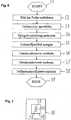
1 zeigt ein Fluoreszenzmikroskop20, das eine Lichtquelle22 umfasst, die einen Beleuchtungslichtstrahl24 erzeugt. Ein erster Strahlteiler28 lenkt den Beleuchtungslichtstrahl24 hin zu einer ersten Spiegelvorrichtung26. Die erste Spiegelvorrichtung26 lenkt Teilstrahlen30 des Beleuchtungslichtstrahls24 hin zu dem ersten Strahlteiler28, wobei dieser die Teilstrahlen30 hin zu einem ersten Linsensystem32 durchlässt. Das erste Linsensystem32 bildet die Teilstrahlen30 auf einen zweiten Strahlteiler34 ab, der die Teilstrahlen30 hin zu einem Objektiv36 ablenkt. Das Objektiv36 fokussiert die Teilstrahlen30 auf oder in einer Probe40, die von einem Probenhalter38 gehalten ist. Jeder fokussierte Teilstrahl30 ruft je einen Beleuchtungsfokus42 auf bzw. in der Probe40 hervor. Die übrigen Anteile des Beleuchtungslichtstrahls24 außer den Teilstrahlen30 werden von der ersten Spiegelvorrichtung26 kompensiert oder so abgelenkt, dass sie nicht hin zu der Probe40 weitergeführt werden. 1 shows afluorescence microscope 20 that is alight source 22 comprising an illuminatinglight beam 24 generated. Afirst beam splitter 28 directs theillumination light beam 24 towards afirst mirror device 26 , Thefirst mirror device 26 directspartial beams 30 of theillumination light beam 24 towards thefirst beam splitter 28 where this is the sub-beams 30 towards afirst lens system 32 pass through. Thefirst lens system 32 forms thepartial beams 30 to asecond beam splitter 34 from which the sub-beams 30 towards alens 36 distracting. The objective 36 focuses thepartial beams 30 on or in asample 40 taken from asample holder 38 is held. Each focused sub-beam 30 ever gets alighting focus 42 on or in thesample 40 out. The remaining portions of theillumination light beam 24 except for the sub-beams 30 be from thefirst mirror device 26 compensated or so distracted that they did not go to thesample 40 be continued.

Die Probe40 umfasst Farbstoffpartikel, die an Probenmoleküle, beispielsweise Proteine, der Probe40 gekoppelt sind und die zum Fluoreszieren anregbar sind. Die Farbstoffpartikel können zum Fluoreszieren angeregt werden und umfassen beispielsweise fluoreszierende Proteine, wie zum Beispiel GFP, PA-GFP, Kaede, Kindling, Dronpa, PS-CFP oder viele andere. Die Farbstoffpartikel, die sich in den Beleuchtungsfoki42 befinden, emittieren Fluoreszenzlicht44, das über das Objektiv36 und den Strahlteiler34 auf ein zweites Linsensystem46 gerichtet ist. Das zweite Linsensystem46 bildet das Fluoreszenzlicht44 auf einen dritten Strahlteiler47 ab, der das Fluoreszenzlicht44 in einen ersten Detektionsteilstrahl48 und einen zweiten Detektionsteilstrahl54 aufteilt und der den ersten Detektionsteilstrahl48 über einen ersten Sperrfilter50 hin zu einer ersten Detektorvorrichtung52 durchlässt und der den zweiten Detektionsteilstrahl54 über einen zweiten Sperrfilter56 hin zu einer zweiten Detektorvorrichtung58 reflektiert.Thesample 40 includes dye particles attached to sample molecules, such as proteins, of thesample 40 are coupled and which can be excited to fluoresce. The dye particles can be made to fluoresce and include, for example, fluorescent proteins such as GFP, PA-GFP, Kaede, Kindling, Dronpa, PS-CFP or many others. The dye particles that are in theBeleuchtungsfoki 42 are located, emit fluorescent light 44 That's about thelens 36 and thebeam splitter 34 on asecond lens system 46 is directed. Thesecond lens system 46 forms thefluorescent light 44 on a third beam splitter 47 off, thefluorescent light 44 in afirst detection sub-beam 48 and asecond detection sub-beam 54 divides and thefirst detection sub-beam 48 via a first blockingfilter 50 towards afirst detector device 52 lets through and thesecond detection sub-beam 54 via asecond blocking filter 56 towards asecond detector device 58 reflected.

2 zeigt eine Anzeigeeinheit59, beispielsweise einen Bildschirm, auf dem ein Bild61 der Probe40 dargestellt ist. Auf der Anzeigeeinheit59 sind Teilbereiche63 der Anzeigeeinheit59 gekennzeichnet. Die Teilbereiche63 sind von einem Benutzer beliebig ausgewählt. Das heißt, dass der Benutzer mit Hilfe einer Benutzereingabe in eine nicht dargestellte Auswahlvorrichtung die Anzahl und die Form der Teilbereiche63 beliebig oder nach einer beliebigen Vorgabe auswählen kann. Insbesondere wählt der Benutzer mindestens einen Teilbereich63 aus. Die Auswahlvorrichtung ist beispielsweise von einem Computer umfasst und weist eine Eingabevorrichtung auf, die mit einer Recheneinheit gekoppelt ist, beispielsweise eine Maus oder einen digitalen Computerstift, wobei die Recheneinheit mit der Anzeigeeinheit59 gekoppelt ist. Der Benutzer kann somit individuell und flexibel einstellen, welchen Bereich oder welche Bereiche der Probe40 untersucht werden sollen. Beispielsweise kann der Benutzer die Teilbereiche63 so auswählen, dass Änderungen der Diffusionsfähigkeit einzelner Farbstoffpartikel und der Probenmoleküle, mit denen sie verbunden sind, beim Übergang von einer Probenstruktur in eine andere Probenstruktur beobachtbar sind, beispielsweise bei Diffusion durch eine Zellmembran der Probe. Die Änderung der Diffusionsfähigkeit der Probenmoleküle kann ein Nachweis von Wechselwirkungen der Probenmoleküle untereinander sein, da sich deren Diffusionsfähigkeit bei einer Interaktion verringert. 2 shows adisplay unit 59 For example, a screen on which apicture 61 thesample 40 is shown. On thedisplay unit 59 are subareas 63 thedisplay unit 59 characterized. The subareas 63 are arbitrarily selected by a user. That is, the user with the help of a user input to a selection device, not shown, the number and shape of the sub-areas 63 can select any or according to any specification. In particular, the user selects at least asubarea 63 out. The selection device is, for example, comprised by a computer and has an input device which is coupled to a computing unit, for example a mouse or a digital computer pen, the computing unit having thedisplay unit 59 is coupled. The user can thus individually and flexibly adjust which area or which areas of thesample 40 to be examined. For example, the user may select the subareas 63 so that changes in the diffusivity of individual dye particles and the sample molecules to which they are attached are observable in the transition from one sample structure to another sample structure, for example when diffused through a cell membrane of the sample. The change in the diffusivity of the sample molecules can be evidence of interactions of the sample molecules with each other, as their diffusibility decreases in an interaction.

3 zeigt die erste Spiegelvorrichtung26, die eine Vielzahl optischer Elemente60 umfasst. Die erste Spiegelvorrichtung26 umfasst einen Mikrospiegelaktor, der als optische Elemente60 einzelne bewegliche Spiegel umfasst. Die optischen Elemente60 umfassen mehrere aktive optische Elemente62, die in3 als geschwärzte Bereiche gekennzeichnet sind. Die aktiven optischen Elemente62 sind dadurch charakterisiert, dass sie mindestens drei vorzugsweise mehr Teilstrahlen30 des Beleuchtungslichtstrahls24 so reflektieren, dass die Teilstrahlen30 über das erste Linsensystem32 und das Objektiv36 auf die Probe40 gerichtet sind. Die übrigen optischen Elemente60 sind so eingestellt, insbesondere sind die beweglichen Spiegel so verkippt, dass die dadurch reflektierten Teilstrahlen30 nicht über das Objektiv36 auf die Probe40 fokussiert sind oder dass diese Anteile des Beleuchtungslichtstrahls24 überhaupt nicht von den entsprechenden Spiegeln reflektiert sondern vielmehr absorbiert werden. Die erste Spiegelvorrichtung26 umfasst vorzugsweise ein Mikrospiegel-Array (Digital Mirror Device) mit einzeln ansteuerbaren beweglichen Spiegeln. Alternativ dazu kann die erste Spiegelvorrichtung einen LCOS-Aktor mit mehreren LCOS-Chips (Liquid Crystal an Silicon) umfassen, wobei die LCOS's im ersten Schaltzustand Licht zu einem verspiegelten Bereich hinter den entsprechenden LCOS's und zurück durchlassen und wobei die LCOS's im zweiten Schaltzustand das Licht zu dem verspiegelten Bereich hinter den entsprechenden LCOS's nicht durchlassen. Beispielsweise können die LCOS's als Polarisationsfilter genutzt werden und das Beleuchtungslicht kann derart polarisiert erzeugt werden oder mit Hilfe des ersten Strahlteilers28 derart polarisiert werden, dass dann abhängig von dem Schaltzustand der LCOS's das Beleuchtungslicht selektiv absorbiert und nicht reflektiert oder reflektiert wird. 3 shows thefirst mirror device 26 containing a variety ofoptical elements 60 includes. Thefirst mirror device 26 comprises a micro-mirror actuator serving asoptical elements 60 includes single movable mirror. Theoptical elements 60 comprise several activeoptical elements 62 , in the 3 are marked as blackened areas. The activeoptical elements 62 are characterized in that they have at least three, preferably more sub-beams 30 of theillumination light beam 24 so reflect that the sub-beams 30 over thefirst lens system 32 and thelens 36 to thetest 40 are directed. The remainingoptical elements 60 are set so, in particular, the movable mirrors are tilted so that the partial beams reflected thereby 30 not over thelens 36 to thetest 40 are focused or that these portions of theillumination light beam 24 not at all reflected by the corresponding mirrors but rather absorbed. Thefirst mirror device 26 preferably comprises a micromirror array (Digital Mirror Device) with individually controllable movable mirrors. Alternatively, the first mirror device may comprise a LCOS actuator having a plurality of LCOS (liquid crystal on silicon) chips, wherein the LCOSs in the first switching state transmit light to a mirrored area behind the corresponding LCOSs and back and the LCOSs in the second switching state Do not allow the mirrored area behind the corresponding LCOS's. For example, the LCOSs can be used as a polarization filter and the illumination light can be generated in such a polarized manner or with the aid of thefirst beam splitter 28 be polarized such that then depending on the switching state of the LCOS's, the illumination light is selectively absorbed and not reflected or reflected.

4 zeigt den Probenhalter38 aus Sicht des Objektivs36. Der Probenhalter38 hält die Probe40, welche eine Probenstruktur65 aufweist. Die Probenstruktur65 umfasst beispielsweise ein Zellmembran oder eine Kernhülle eines Zellkerns der Probe40. Beleuchtungsbereiche43 auf der Probe40 korrespondieren zu den ausgewählten Teilbereichen63 auf der Anzeigeeinheit59. Die Beleuchtungsbereiche43 werden mit mehreren Beleuchtungsfoki42 ausgeleuchtet, die durch die Teilstrahlen30 hervorgerufen werden, die von den aktiven optischen Elementen62 hin zu der Probe40 gelenkt werden. Die einzelnen Beleuchtungsfoki42, aus denen sich die Beleuchtungsbereiche43 zusammensetzen, sind aus Gründen der Übersichtlichkeit in4 nicht eingezeichnet. Alternativ dazu können die Beleuchtungsbereiche43 auch so klein gewählt werden, dass sie mit lediglich einem Beleuchtungsfokus42 ausgeleuchtet werden können. 4 shows thesample holder 38 from the perspective of thelens 36 , Thesample holder 38 holds thesample 40 which is asample structure 65 having. Thesample structure 65 For example, it includes a cell membrane or a nuclear envelope of a nucleus of thesample 40 ,lighting areas 43 on thetest 40 correspond to the selectedsubareas 63 on thedisplay unit 59 , Thelighting areas 43 be withseveral lighting foci 42 illuminated by thepartial beams 30 caused by the activeoptical elements 62 to thesample 40 be steered. Theindividual lighting foci 42 that make up thelighting areas 43 for clarity, are in 4 not shown. Alternatively, thelighting areas 43 also be chosen so small that they have only oneillumination focus 42 can be illuminated.

5 zeigt eine Oberfläche der Detektorvorrichtungen52,58. Die jeweilige Detektorvorrichtung52,58 weist an ihrer Oberfläche eine sensitive Fläche auf, die durch eine Vielzahl von Detektorelementen64 ausgebildet ist. Die Detektionsteilstrahlen48,54 sind so auf die sensitive Fläche der Detektorvorrichtungen52,58 gerichtet, dass mehrere Detektionsfoki in je einem Detektionsbereich68 auf der sensitiven Fläche entstehen. Die Detektionsfoki korrespondieren zu den Beleuchtungsfoki42 auf der Probe40 und zu den aktiven optischen Elementen62 der ersten Spiegelvorrichtung26 und die beleuchteten Detektionsbereiche68 korrespondieren zu den Beleuchtungsbereichen43 auf der Probe40 und zu den Teilbereichen63 auf der Anzeigeeinheit59. Die Detektorelemente64 sind vorzugsweise CMOS-Detektoren oder alternativ dazu APD's oder DEPFET-Detektoren. 5 shows a surface of thedetector devices 52 . 58 , Therespective detector device 52 . 58 has on its surface on a sensitive surface, which by a plurality ofdetector elements 64 is trained. Thedetection sub-beams 48 . 54 are so on the sensitive surface of thedetector devices 52 . 58 directed that multiple detection foci in eachdetection area 68 arise on the sensitive surface. The detection foci correspond to theillumination foci 42 on thetest 40 and to the activeoptical elements 62 thefirst mirror device 26 and the illuminateddetection areas 68 correspond to thelighting areas 43 on thetest 40 and to the subareas 63 on thedisplay unit 59 , Thedetector elements 64 are preferably CMOS detectors or alternatively APD's or DEPFET detectors.

6 zeigt ein Ablaufdiagramm eines Programms zum Durchführen einer Multipoint-FCS mit dem Fluoreszenzmikroskop20. Bei der bekannten Fluoreszenz-Korrelations-Spektroskopie (FCS) werden Diffusionskonstanten einzelner Probenmoleküle mit Hilfe eines oder zwei Beleuchtungsfoki42 ermittelt. Bei der Multipoint-FCS werden Diffusionskonstanten einzelner Probenmoleküle mit Hilfe von drei oder mehr Beleuchtungsfoki42 ermittelt, wobei die Beleuchtungsfoki42 auf die Beleuchtungsbereiche43 der Probe40 gerichtet sind und diese ausleuchten. Abhängig von den Diffusionskonstanten können dann die Konzentration der Probenmoleküle ermittelt werden und Interaktionen zwischen den Probenmolekülen nachgewiesen werden. Das Programm dient dazu, zumindest den Diffusionskoeffizienten von einer Sorte von Probenmolekülen der Probe40 zu ermitteln. Das Programm wird vorzugsweise in einem Schritt S1 gestartet, beispielsweise zeitnah zu einer Inbetriebnahme des Fluoreszenzmikroskops20. 6 Fig. 10 is a flow chart of a program for performing a multipoint FCS with thefluorescence microscope 20 , In the known fluorescence correlation spectroscopy (FCS) diffusion constants of individual sample molecules with the help of one or twoBeleuchtungsfoki 42 determined. In multipoint FCS, diffusion constants of individual sample molecules are determined using three ormore illumination factors 42 determined, theBeleuchtungsfoki 42 on thelighting areas 43 thesample 40 are directed and illuminate them. Depending on the diffusion constants, the concentration of the sample molecules can then be determined and interactions between the sample molecules can be detected. The program serves at least the diffusion coefficient of one sort of sample molecules of thesample 40 to investigate. The program is preferably started in a step S1, for example, in a timely manner when the fluorescence microscope is put intooperation 20 ,

In einem Schritt S2 wird das Bild61 der Probe40 aufgenommen. Das Bild61 kann beispielsweise mit Hilfe der Widefield-Aufnahme aufgenommen werden, bei der alle optischen Elemente60 der ersten Spiegelvorrichtung26 aktiv sind und so nahezu der gesamte Beleuchtungslichtstrahl24 hin zu der Probe40 gelenkt wird und bei der alle Detektorelemente64 der beiden Detektorvorrichtungen52,58 ausgelesen und ausgewertet werden.In a step S2, the image becomes 61 thesample 40 added. Thepicture 61 can be recorded, for example, using the Widefield recording, in which all theoptical elements 60 thefirst mirror device 26 are active and so almost the entireillumination light beam 24 to thesample 40 is steered and at the alldetector elements 64 the twodetector devices 52 . 58 be read out and evaluated.

In einem Schritt S3 wählt ein Benutzer des Fluoreszenzmikroskops20 mit Hilfe der Auswahlvorrichtung anhand des Bildes61 der Probe40 auf der Anzeigeeinheit59 einen oder mehrere der Teilbereiche63 aus, wobei sowohl die Anzahl als auch die Form der Teilbereiche63 von dem Benutzer beliebig gewählt werden kann.In a step S3, a user of the fluorescence microscope selects 20 using the selection device based on theimage 61 thesample 40 on thedisplay unit 59 one or more of the subareas 63 with both the number and the shape of thesubregions 63 can be chosen arbitrarily by the user.

In einem Schritt S4 wird mit Hilfe der Steuereinheit abhängig von den durch den Benutzer vorgegebenen Teilbereichen63 auf der Anzeigeeinheit59 die erste Spiegelvorrichtung26 so angesteuert, dass genau die optischen Elementen60 der ersten Spiegelvorrichtung26 aktiviert werden, die den Beleuchtungslichtstrahl24 so aufteilen und die entsprechenden Teilstrahlen30 so reflektieren, dass diese Teilstrahlen30 Beleuchtungsfoki42 auf der Probe40 derart bewirken, dass die zu den Teilbereichen63 korrespondierenden Beleuchtungsbereiche43 der Probe40 ausgeleuchtet sind.In a step S4, with the aid of the control unit, it is dependent on the subregions predetermined by theuser 63 on thedisplay unit 59 thefirst mirror device 26 so driven that exactly theoptical elements 60 thefirst mirror device 26 be activated, the illuminatinglight beam 24 divide so and the corresponding sub-beams 30 so reflect that these sub-beams 30illumination foci 42 on thetest 40 cause such that thesubregions 63 correspondingillumination areas 43 thesample 40 are lit up.

In einem Schritt S5 werden die Farbstoffpartikel in den Beleuchtungsfoki42 zum Fluoreszieren angeregt. Falls Farbstoffpartikel verwendet werden, die einen ersten Zustand haben, in dem die Farbstoffpartikel zum Fluoreszieren anregbar sind, und die einen zweiten Zustand haben, in dem die Farbstoffpartikel nicht zum Fluoreszieren anregbar sind, so wird vor dem Schritt S5 eine Untermenge der Farbstoffpartikel im ersten Zustand erzeugt. Bekannte Mikroskopieverfahren, die dies ausnutzen sind beispielsweise PALM, STORM, FPALM, DSTORM, GSDIM und weitere. Bekannte Farbstoffpartikel die dabei verwendet werden sind beispielsweise PA-GFP, PS-CFP etc.In a step S5, the dye particles in theBeleuchtungsfoki 42 excited to fluoresce. If dye particles are used which have a first state in which the dye particles are excitable for fluorescence and which have a second state in which the dye particles are not excitable for fluorescence, a subset of the dye particles becomes in the first state before step S5 generated. Known microscopy methods that exploit this are, for example, PALM, STORM, FPALM, DSTORM, GSDIM and others. Known dye particles which are used are, for example, PA-GFP, PS-CFP, etc.

In einem Schritt S6 werden abhängig von den ausgewählten Teilbereichen63 die Detektorelemente64 ermittelt, auf die die Detektionsteilstrahlen48,54 in Form der Detektionsfoki fokussiert sind.In a step S6, depending on the selectedsubregions 63 thedetector elements 64 determined on the detectionpartial beams 48 . 54 are focused in the form of Detektionsfoki.

In einem Schritt S7 werden die in dem Schritt S6 ermittelten Detektorelemente64 ausgelesen und deren Daten werden ausgewertet. Alternativ dazu können alle Detektorelemente64 ausgelesen werden, aber nur die Daten der in dem Schritt S6 ermittelten Detektorelemente64 ausgewertet werden. Dieses selektive Auslesen und/oder Auswerten der Detektionsbereiche68 trägt zu einem besonders Schnellen Ermitteln der Diffusionskoeffizienten bei.In a step S7, the detector elements determined in step S6 become 64 read out and their data are evaluated. Alternatively, alldetector elements 64 but only the data of the detector elements determined instep S6 64 be evaluated. This selective reading and / or evaluation of thedetection areas 68 contributes to a particularly fast determination of the diffusion coefficients.

Abhängig von den ausgewerteten Daten wird zumindest ein Diffusionskoeffizient von Probenmolekülen der Probe40 ermittelt. Alternativ oder zusätzlich kann die Probenmolekülkonzentration einzelner Probenmoleküle in den ausgewählten Teilbereichen63 ermittelt werden. Anhand der Diffusionskoeffizienten können Interaktionen der Probenmoleküle untereinander beobachtet werden, da in der Regel die Diffusionsfähigkeit der Probenmoleküle abnimmt, sobald diese eine Interaktion mit anderen Probenmolekülen eingehen.Depending on the evaluated data at least one diffusion coefficient of sample molecules of thesample 40 determined. Alternatively or additionally, the sample molecule concentration of individual sample molecules in the selectedsubregions 63 be determined. Interaction of the sample molecules with each other can be observed on the basis of the diffusion coefficients since, as a rule, the diffusibility of the sample molecules decreases as soon as they interact with other sample molecules.

In einem Schritt S9 kann das Programm beendet werden. Vorzugsweise wird das Programm jedoch fortlaufend während des Betriebs des Fluoreszenzmikroskops20 abgearbeitet, insbesondere jedes Mal dann, wenn der Benutzer neue Teilbereiche63 anhand der Darstellung des Bildes61 auf der Anzeigeeinheit59 auswählt.In a step S9, the program can be ended. Preferably, however, the program will continue to run during operation of thefluorescence microscope 20 processed, in particular, every time the usernew subareas 63 based on the representation of thepicture 61 on thedisplay unit 59 selects.

7 zeigt ein zweites Ausführungsbeispiel, bei dem die Beleuchtungsfoki42 derart aneinander gereiht sind, dass sich bewegende Probenmoleküle in der Probe40 über eine größere Strecke beobachtet werden können. Das Erzeugen mehrerer aneinandergereihter Beleuchtungsfoki42 ermöglicht besonders gut, Nachbarschaftsbeziehungen der Probenmoleküle zueinander zu untersuchen. 7 shows a second embodiment in which theBeleuchtungsfoki 42 are strung together so that moving sample molecules in thesample 40 can be observed over a longer distance. Creating multiple juxtaposedillumination foci 42 makes it particularly easy to study neighborhood relationships of the sample molecules to each other.

8 zeigt ein Ablaufdiagramm eines Programms zum Einstellen einer Konfokalität des Fluoreszenzmikroskops20. Das Programm wird vorzugsweise in einem Schritt S10 gestartet, in dem gegebenenfalls Variablen initialisiert werden. In einem Schritt S11 wird die gewünschte Konfokalität von dem Benutzer vorgegeben. Abhängig von der eingegebenen Konfokalität wird in einem Schritt S12 die Anzahl der Detektorelemente64 ermittelt, die je Beleuchtungsfokus42 und entsprechendem Detektionsfokus ausgelesen bzw. ausgewertet werden. Je größer die Konfokalität ist, desto weniger Detektorelemente64 je Detektionsfokus werden ausgelesen. Je kleiner die Konfokalität vorgegeben wird, desto mehr Detektorelemente64 je Detektionsfokus können ausgelesen werden. In einem Schritt S13 kann das Programm beendet werden. Vorzugsweise wird jedoch nach dem Schritt S13 das Programm zum Durchführen der Multipoint-FCS abgearbeitet. 8th FIG. 12 is a flow chart of a program for setting confocality of the fluorescence microscope. FIG 20 , The program is preferably started in a step S10, in which variables are initialized if necessary. In a step S11, the desired confocality is specified by the user. Depending on the confocality entered, the number of detector elements is determined in astep S12 64 determines theever lighting focus 42 and corresponding detection focus can be read out or evaluated. The greater the confocality, thefewer detector elements 64 each detection focus is read out. The smaller the confocality is given, themore detector elements 64 each detection focus can be read out. In a step S13, the program can be ended. Preferably, however, after the step S13, the program for executing the multipoint FCS is executed.

Aufgrund der mehreren Beleuchtungsfoki42 innerhalb eines oder mehrerer der Beleuchtungsbereiche43 kann es zu einem optischen Crosstalk, insbesondere zu einem Überlappen mehrerer Beleuchtungslichtkegel oder Detektionslichtkegel kommen. Dies führt zu Streulicht und einem unerwünschten Hintergrundsignal, welches mit zunehmender Probendicke stärker wird.Due to themultiple lighting foci 42 within one or more of thelighting areas 43 This can lead to an optical crosstalk, in particular to an overlap of several illumination light cones or detection light cones. This leads to stray light and an undesirable background signal, which becomes stronger with increasing sample thickness.

9 zeigt eine zweite Ausführungsform des Fluoreszenzmikroskops20, bei der die Fluoreszenzlichtstrahlen44 vor der Detektion auf eine zweite Spiegelvorrichtung70 treffen, die zu einem Verringern und/oder Vermeiden des unerwünschten Hintergrundsignals dient. Die zweite Spiegelvorrichtung70 kann entsprechend der ersten Spiegelvorrichtung26 ausgebildet sein und einen Mikrospiegelaktor, insbesondere mehrere ansteuerbare optische Elemente, aufweisen. Die optischen Elemente der zweiten Spiegelvorrichtung70 sind abhängig von ihrem Schaltzustand aktiv oder passiv. Die aktiven optischen Elemente der zweiten Spiegelvorrichtung70 lenken die auf sie gerichteten Fluoreszenzlichtstrahlen44 über einen Spiegel72 hin zu der ersten Detektorvorrichtung52. Die räumliche Anordnung und Ausrichtung der zweiten Spiegelvorrichtung70 ist präzise an die räumliche Anordnung und Ausrichtung der ersten Spiegelvorrichtung26 angepasst. Da sich die beiden Spiegelvorrichtungen26,70 in zur Probe40 konjugierten Ebenen befinden, ist es wichtig, dass der optische Weg von der ersten Spiegelvorrichtung26 zur Probe dem optischen Weg von der Probe40 zur zweiten Spiegelvorrichtung70 entspricht. Daher ist bei diesem Ausführungsbeispiel das erste Linsensystem32 zwischen dem zweiten Strahlteiler34 und dem Objektiv36 angeordnet, so dass sowohl das Beleuchtungslicht als auch das Detektionslicht das erste Linsenssystem32 durchlaufen. Ferner sollte der Abstand von der Probe40 zu der ersten Spiegelvorrichtung26 genau so lang sein wie der Abstand von der Probe40 zu der zweiten Spiegelvorrichtung70. 9 shows a second embodiment of thefluorescence microscope 20 in which the fluorescent light rays 44 before detection on asecond mirror device 70 meeting, which serves to reduce and / or avoid the unwanted background signal. Thesecond mirror device 70 can according to thefirst mirror device 26 be formed and a micro-mirror actuator, in particular a plurality of controllable optical elements have. The optical elements of thesecond mirror device 70 are active or passive depending on their switching state. The active optical elements of thesecond mirror device 70 direct the fluorescent light rays directed at them 44 over amirror 72 towards thefirst detector device 52 , The spatial arrangement and orientation of thesecond mirror device 70 is precise to the spatial arrangement and orientation of thefirst mirror device 26 customized. Because the twomirror devices 26 . 70 in to therehearsal 40 It is important that the optical path from thefirst mirror device 26 to sample the optical path from thesample 40 to thesecond mirror device 70 equivalent. Therefore, in this embodiment, thefirst lens system 32 between thesecond beam splitter 34 and thelens 36 arranged so that both the illumination light and the detection light, thefirst lens system 32 run through. Further, the distance from the sample should be 40 to thefirst mirror device 26 be as long as the distance from thesample 40 to thesecond mirror device 70 ,

Die zweite Spiegelvorrichtung70 ist vorzugsweise mit der Steuereinheit gekoppelt, die die optischen Elemente der zweiten Spiegelvorrichtung70 korrespondierend zu den optischen Elementen60 der ersten Spiegelvorrichtung26 steuert. Das bedeutet, dass ein durch die aktiven optischen Elemente auf der zweiten Spiegelvorrichtung70 repräsentiertes Muster genau dem Muster entspricht, das die aktiven optischen Elemente62 auf der ersten Spiegelvorrichtung26 repräsentieren. Bei einem Umschalten der optischen Elemente60 der ersten Spiegelvorrichtung26 erfolgt dazu korrespondierend auch ein Umschalten der optischen Elemente der zweiten Spiegelvorrichtung70.Thesecond mirror device 70 is preferably coupled to the control unit which comprises the optical elements of thesecond mirror device 70 corresponding to theoptical elements 60 thefirst mirror device 26 controls. This means that one through the active optical elements on thesecond mirror device 70 represented pattern corresponds exactly to the pattern that the activeoptical elements 62 on thefirst mirror device 26 represent. When switching theoptical elements 60 thefirst mirror device 26 Correspondingly, a switching of the optical elements of the second mirror device takes place in acorresponding manner 70 ,

Die Funktionsweise der zweiten Spiegelvorrichtung70 entspricht der einer variablen Lochblende, wobei mit Hilfe der optischen Elemente der zweiten Spiegelvorrichtungen70 sowohl die Position, als auch die Form, als auch die Anzahl der Lochblenden variiert werden kann. Vorzugsweise sind die optischen Elemente60 der ersten Spiegelvorrichtung26 parallel zu den optischen Elementen der zweiten Spiegelvorrichtung70 geschaltet und so zeitlich mit diesen synchronisiert. Somit kann für jeden Teillichtstrahl30 und jeden dazu korrespondierenden Fluoreszenzlichtstrahl44 eine eigene Lochblende erzeugt werden, indem die entsprechenden optischen Elemente der zweiten Spiegelvorrichtung70 aktiviert werden. Dadurch gelangt weniger Streulicht zu der ersten Detektorvorrichtung52 als ohne die zweite Spiegelvorrichtung70.The operation of thesecond mirror device 70 corresponds to that of a variable pinhole, wherein by means of the optical elements of thesecond mirror devices 70 Both the position, as well as the shape, as well as the number of pinholes can be varied. Preferably, theoptical elements 60 thefirst mirror device 26 parallel to the optical elements of thesecond mirror device 70 switched and synchronized with them in time. Thus, for eachpartial light beam 30 and each corresponding fluorescent light beam 44 a separate pinhole can be generated by the corresponding optical elements of thesecond mirror device 70 to be activated. As a result, less stray light reaches thefirst detector device 52 as without thesecond mirror device 70 ,

Vorzugsweise werden um die aktiven optischen Elemente der zweiten Spiegelvorrichtung70 herum, die zu den aktiven optischen Elementen26 der ersten Spiegelvorrichtung26 korrespondieren, weitere optische Elemente der zweiten Spiegelvorrichtung70 aktiviert, da bei fluoreszierenden Proben40 die Emissionswellenlänge in der Regel länger ist als die Anregungswellenlänge, wodurch auch der auf die zweite Spiegelvorrichtung70 projizierte Fokus des Fluoreszenzlichts44 größer als der Beleuchtungsfokus42 ist. Dies entspricht einer Vergrößerung der Lochblende und trägt dazu bei, dass möglichst wenig Fluoreszenzlicht44 verloren geht. Will man eine geringe Konfokalität erzielen, können entsprechend mehr optische Elemente der zweiten Spiegelvorrichtung70 aktiviert werden.Preferably, around the active optical elements of thesecond mirror device 70 around, leading to the activeoptical elements 26 thefirst mirror device 26 correspond, further optical elements of thesecond mirror device 70 activated, as influorescent samples 40 the emission wavelength is usually longer than the excitation wavelength, which also affects thesecond mirror device 70 projected focus of thefluorescent light 44 greater than theillumination focus 42 is. This corresponds to an enlargement of the pinhole and helps to minimize thefluorescent light 44 get lost. If you want to achieve a low confocality, correspondingly more optical elements of thesecond mirror device 70 to be activated.

Bei FCS Messungen ist es auch von Vorteil unterschiedliche Detektionsvolumina einstellen zu können, um bessere Aussagen über die Diffusionsgeschwindigkeit zu erhalten, dies kann über die Größe der Lochblenden vor der Detektorvorrichtung52 bestimmt werden.In FCS measurements, it is also advantageous to be able to set different detection volumes in order to obtain better information about the diffusion rate, this can be determined by the size of the pinhole diaphragms in front of thedetector device 52 be determined.

Die Erfindung ist nicht auf die angegebenen Ausführungsbeispiele beschränkt. Beispielsweise können mehr oder weniger Detektorvorrichtungen52,58 angeordnet sein. Ferner können mehr oder weniger Linsensysteme32,46 angeordnet sein. Ferner kann die Lichtquelle22 einen oder mehrere Laser umfassen, der bzw. die Beleuchtungslicht unterschiedlicher Wellenlänge erzeugen. Dies ermöglicht, unterschiedliche Farbstoffpartikel zum Fluoreszieren anzuregen, und so unterschiedliche Probenmoleküle gleichzeitig zu beobachten. Beim Ausleuchten der Beleuchtungsbereiche43 können die Abstände der Beleuchtungsfoki zueinander variiert werden, indem innerhalb der Beleuchtungsbereiche43 einzelne mögliche Beleuchtungsfoki42 nicht erzeugt und somit ausgelassen werden. Der Beleuchtungslichtstrahl kann Licht unterschiedlicher Wellenlängen umfassen, so dass gleichzeitig Farbstoffpartikel unterschiedlicher Farbe zum Fluoreszieren angeregt werden können, wodurch gleichzeitig mehrere unterschiedliche Sorten von Probenmolekülen beobachtet werden können und deren Diffusionskoeffizienten gleichzeitig bestimmt werden können. Bei der zweiten Ausführungsform des Fluoreszenzmikroskops20 kann auch die zweite Detektorvorrichtung58 angeordnet sein. Ferner kann das Fluoreszenzmikroskop20 weit mehr optische Komponenten, beispielsweise Linsen umfassen. Insbesondere können Linsen zwischen der Lichtquelle22 und dem ersten Strahlteiler28 und/oder zwischen der zweiten Spiegelvorrichtung70 und der ersten Detektorvorrichtung52 angeordnet sein. Alternativ zu der zweiten Spiegelvorrichtung70 kann das Fluoreszenzlicht44 auch über die erste Spiegelvorrichtung26 zu der Detektorvorrichtung52 geführt werden, wobei dann ein Variieren der Lochblendengröße nicht mehr möglich ist, da mit Hilfe der ersten Spiegelvorrichtung26 die Teilstrahlen30 erzeugt werden.The invention is not limited to the specified embodiments. For example, more orless detector devices 52 . 58 be arranged. Furthermore, more or less lens systems may be used 32 . 46 be arranged. Furthermore, thelight source 22 comprise one or more lasers that generate illumination light of different wavelengths. This makes it possible to stimulate different dye particles to fluoresce, and thus to observe different sample molecules simultaneously. When illuminating thelighting areas 43 For example, the distances of the illumination foci from each other can be varied by within theillumination areas 43 singlepossible lighting foci 42 not generated and thus omitted. The illumination light beam may comprise light of different wavelengths, so that at the same time dye particles of different colors can be excited to fluoresce, whereby simultaneously several different types of sample molecules can be observed and their diffusion coefficients can be determined simultaneously. In the second embodiment of thefluorescence microscope 20 can also be thesecond detector device 58 be arranged. Furthermore, thefluorescence microscope 20 far more optical components, such as lenses include. In particular, lenses can be placed between thelight source 22 and thefirst beam splitter 28 and / or between thesecond mirror device 70 and thefirst detector device 52 be arranged. Alternative to thesecond mirror device 70 can thefluorescent light 44 also on thefirst mirror device 26 to thedetector device 52 be guided, in which case a variation of the pinhole size is no longer possible because with the aid of thefirst mirror device 26 thepartial beams 30 be generated.

BezugszeichenlisteLIST OF REFERENCE NUMBERS

2020
Fluoreszenz-MikroskopFluorescence microscope
2222
Lichtquellelight source
2424
BeleuchtungslichtstrahlIlluminating light beam
2626
erste Spiegelvorrichtungfirst mirror device
2828
erster Strahlteilerfirst beam splitter
3030
Teilstrahlenpartial beams
3232
erstes Linsensystemfirst lens system
3434
zweiter Strahlteilersecond beam splitter
3636
Objektivlens
3838
Probenhaltersample holder
4040
Probesample
4242
Beleuchtungsfokusfocus lighting
4343
Beleuchtungsbereichlighting area
4444
Fluoreszenzlichtfluorescent light
4646
zweites Linsensystemsecond lens system
4747
dritter Strahlteilerthird beam splitter
4848
erster Detektionsteilstrahlfirst detection sub-beam
5050
erster Sperrfilterfirst barrier filter
5252
erste Detektorvorrichtungfirst detector device
54 54
zweiter Detektionsteilstrahlsecond detection sub-beam
5656
zweiter Sperrfiltersecond barrier filter
5858
zweite Detektorvorrichtungsecond detector device
5959
Anzeigeeinheitdisplay unit
6060
optische Elementeoptical elements
6161
Bildimage
6262
aktive optische Elementeactive optical elements
6363
Teilbereichesubregions
6464
Detektorelementedetector elements
6565
Probenstruktursample structure
6868
Detektionsbereichdetection range
7070
zweite Spiegelvorrichtungsecond mirror device
7272
Spiegelmirror

ZITATE ENTHALTEN IN DER BESCHREIBUNG QUOTES INCLUDE IN THE DESCRIPTION

Diese Liste der vom Anmelder aufgeführten Dokumente wurde automatisiert erzeugt und ist ausschließlich zur besseren Information des Lesers aufgenommen. Die Liste ist nicht Bestandteil der deutschen Patent- bzw. Gebrauchsmusteranmeldung. Das DPMA übernimmt keinerlei Haftung für etwaige Fehler oder Auslassungen.This list of the documents listed by the applicant has been generated automatically and is included solely for the better information of the reader. The list is not part of the German patent or utility model application. The DPMA assumes no liability for any errors or omissions.

Zitierte Nicht-PatentliteraturCited non-patent literature

  • „Two-Focus Fluorescene Correlation Spectroscopy, Dissertation von Thomas Dertinger an der Universität Köln, 2007[0002]"Two-Focus Fluorescene Correlation Spectroscopy, Dissertation by Thomas Dertinger at the University of Cologne, 2007[0002]

Claims (17)

Translated fromGerman
Verfahren zur Durchführung einer Fluoreszenz-Korrelations-Spektroskopie mit einem Fluoreszenz-Mikroskop (29), bei dem ein Beleuchtungslichtstrahl (24) erzeugt wird, mindestens ein Beleuchtungsbereich (43) einer Probe (40) ausgewählt wird, der Beleuchtungslichtstrahl (24) in mindestens drei Teilstrahlen (30) so aufgespaltet wird, dass die Teilstrahlen (30) über eine Mikroskopoptik des Fluoreszenz-Mikroskops (29) auf den ausgewählten Beleuchtungsbereich (43) fokussiert werden, so dass fluoreszierende Farbstoffpartikel in dem Beleuchtungsbereich (43) der Probe (40) zum Fluoreszieren angeregt werden, das von den Farbstoffpartikeln emittierte Fluoreszenzlicht (44) detektiert wird und bei dem abhängig von dem detektierten Fluoreszenzlicht (44) mindestens ein Diffusionskoeffizient ermittelt wird, der repräsentativ für eine Diffusionsfähigkeit der fluoreszierenden Farbstoffpartikel ist.Method for carrying out fluorescence correlation spectroscopy with a fluorescence microscope ( 29 ), in which an illumination light beam ( 24 ), at least one lighting area ( 43 ) of a sample ( 40 ), the illuminating light beam ( 24 ) into at least three partial beams ( 30 ) is split so that the partial beams ( 30 ) via a microscope optics of the fluorescence microscope ( 29 ) to the selected lighting area ( 43 ) are focused so that fluorescent dye particles in the illumination area ( 43 ) of the sample ( 40 ) are excited to fluoresce, the fluorescent light emitted by the dye particles ( 44 ) is detected and in which, depending on the detected fluorescent light ( 44 ) at least one diffusion coefficient is determined, which is representative of a diffusibility of the fluorescent dye particles.Verfahren nach Anspruch 1, bei dem ein Bild (61) der Probe (40) auf einer Anzeigeeinheit (59) angezeigt wird, mindestens ein Teilbereich (63) des Bildes (61) der Probe (40) ausgewählt wird, ermittelt wird, wie der Beleuchtungslichtstrahl (24) aufgespaltet werden muss, damit die Teilstrahlen (30) auf den Beleuchtungsbereich (43) der Probe (40) fokussiert werden, wobei der Beleuchtungsbereich (43) der Probe (30) abhängig von dem ausgewählten Teilbereich (63) des Bildes (61) der Probe (30) ausgewählt wird und zu diesem korrespondiert, und bei dem der Beleuchtungslichtstrahl (24) so in die Teilstrahlen (30) aufgespaltet wird, dass fluoreszierende Farbstoffpartikel in dem Beleuchtungsbereich (43) der Probe (40) zum Fluoreszieren angeregt werden.Method according to Claim 1, in which an image ( 61 ) of the sample ( 40 ) on a display unit ( 59 ), at least one subarea ( 63 ) of the picture ( 61 ) of the sample ( 40 ), it is determined how the illumination light beam ( 24 ) must be split so that the partial beams ( 30 ) to the lighting area ( 43 ) of the sample ( 40 ), the illumination area ( 43 ) of the sample ( 30 ) depending on the selected subarea ( 63 ) of the picture ( 61 ) of the sample ( 30 ) and corresponds to it, and in which the illumination light beam ( 24 ) so in the partial beams ( 30 ) is split that fluorescent dye particles in the illumination area ( 43 ) of the sample ( 40 ) are excited to fluoresce.Verfahren nach einem der vorstehenden Ansprüche, bei dem abhängig von dem oder den Diffusionskoeffizienten eine Interaktion zwischen Probenmolekülen erkannt wird, die mit den Farbstoffpartikeln gekoppelt sind, deren Diffusionskoeffizienten ermittelt wurden.Method according to one of the preceding claims, in which, depending on the diffusion coefficient or coefficients, an interaction between sample molecules is detected, which are coupled to the dye particles whose diffusion coefficients were determined.Verfahren nach einem der vorstehenden Ansprüche, bei dem das Fluoreszenzlicht auf eine sensitive Fläche einer Detektorvorrichtung (52,58), die mehrere Detektorelemente (64) umfasst, gelenkt wird und dort entsprechend zu den auf den Beleuchtungsbereich (43) der Probe (40) fokussierten Teilstrahlen (30) mindestens drei Detektionsfoki entstehen, abhängig von dem Beleuchtungsbereich (43) der Probe (40) Positionen der Detektionsfoki auf der sensitiven Fläche der Detektorvorrichtung (52,58) ermittelt werden und bei dem selektiv nur die Detektorelemente (64) ausgelesen und/oder deren Signale ausgewertet werden, auf denen die Detektionsfoki positioniert sind.Method according to one of the preceding claims, in which the fluorescent light is irradiated onto a sensitive surface of a detector device ( 52 . 58 ) comprising a plurality of detector elements ( 64 ) is guided and there corresponding to the on the illumination area ( 43 ) of the sample ( 40 ) focused partial beams ( 30 ) arise at least three detection foci, depending on the illumination area ( 43 ) of the sample ( 40 ) Positions of the detection foci on the sensitive surface of the detector device ( 52 . 58 ) and in which only the detector elements ( 64 ) and / or whose signals are evaluated on which the detection foci are positioned.Verfahren nach Anspruch 4, bei dem eine Konfokalität des Fluoreszenz-Mikroskops (20) eingestellt wird, indem eine Anzahl der Detektorelemente (64), die je Detektionsfokus ausgelesen und/oder ausgewertet werden, eingestellt wird.Method according to Claim 4, in which a confocality of the fluorescence microscope ( 20 ) is adjusted by a number of detector elements ( 64 ), which are read out and / or evaluated per detection focus.Verfahren nach einem der vorstehenden Ansprüche, bei dem Farbstoffpartikel verwendet werden, die einen ersten Zustand haben, in dem die Farbstoffpartikel zum Fluoreszieren anregbar sind, und die einen zweiten Zustand haben, in dem die Farbstoffpartikel nicht zum Fluoreszieren anregbar sind und bei dem eine Untermenge der Farbstoffpartikel im ersten Zustand erzeugt und dann angeregt wird.A method according to any one of the preceding claims, wherein dye particles are used which have a first state in which the dye particles are excitable to fluoresce, and which have a second state in which the dye particles are not excitable to fluoresce and in which a subset of the Dye particles produced in the first state and then excited.Verfahren nach einem der vorstehenden Ansprüche, bei dem mindestens zwei Beleuchtungsbereiche (43) der Probe (40) aneinander gereiht ausgewählt werden, eine Bewegung eines einzelnen Farbstoffpartikels über mehrere der Beleuchtungsbereiche (43) hinweg beobachtet wird und bei dem der oder die Diffusionskoeffizienten des entsprechenden Farbstoffpartikels ermittelt werden.Method according to one of the preceding claims, in which at least two illumination areas ( 43 ) of the sample ( 40 ), a movement of a single dye particle over several of the illumination areas ( 43 ) and in which the diffusion coefficient or coefficients of the corresponding dye particle are determined.Verfahren nach einem der vorstehenden Ansprüche, bei dem der Beleuchtungslichtstrahl (24) gepulst erzeugt wird, abhängig von den Pulsen des Beleuchtungslichtstrahls (24) die Detektorelemente (64) ausgelesen und/oder ausgewertet werden, abhängig von dem detektierten Fluoreszenzlicht Leucht-Lebensdauern der Farbstoffpartikel ermittelt werden und bei dem abhängig von den ermittelten Leucht-Lebensdauern Verbindungen und/oder Interaktionen der Probenmoleküle untersucht werden, die mit den entsprechenden Farbstoffpartikeln gekoppelt sind.Method according to one of the preceding claims, in which the illuminating light beam ( 24 ) is pulsed, depending on the pulses of the illumination light beam ( 24 ) the detector elements ( 64 ) are read out and / or evaluated, depending on the detected fluorescent light luminous lifetimes of the dye particles are determined and examined in the dependent on the determined luminous lifetimes compounds and / or interactions of the sample molecules, which are coupled with the corresponding dye particles.Vorrichtung zur Durchführung einer Fluoreszenz-Korrelations-Spektroskopie umfassend ein Fluoreszenz-Mikroskop (20), mit einer Lichtquelle (22), die einen Beleuchtungslichtstrahl (24) erzeugt, einer ersten Spiegelvorrichtung (26), auf die der Beleuchtungslichtstrahl (24) gerichtet ist und die eine Vielzahl von optischen Elementen (60) aufweist, einer Steuereinheit, die mit der ersten Spiegelvorrichtung (26) gekoppelt ist und die die optischen Elemente (60) so ansteuert, dass die optischen Elemente (60) den Beleuchtungslichtstrahl (24) in mindestens drei Teilstrahlen (30) aufspalten, einer Mikroskopoptik, die die Teilstrahlen (30) des Beleuchtungslichtstrahls (24) auf mindestens einen Beleuchtungsbereich (43) auf oder in einer Probe (40) fokussiert, wobei die Teilstrahlen (30) Farbstoffpartikel in der Probe (40) zum Fluoreszieren anregen, und mit einer Detektorvorrichtung (52,58), die von der Probe (40) emittierte Fluoreszenzlichtlichtstrahlen (44) detektiert und die mehrere Detektorelemente (60) umfasst, wobei die Steuereinheit steuert, welche Detektorelemente (60) ausgelesen und/oder ausgewertet werden.Device for carrying out a fluorescence correlation spectroscopy comprising a fluorescence microscope ( 20 ), with a light source ( 22 ), which emit an illuminating light beam ( 24 ), a first mirror device ( 26 ) to which the illuminating light beam ( 24 ) and a plurality of optical elements ( 60 ), a control unit connected to the first mirror device ( 26 ) and the optical elements ( 60 ) controls so that the optical elements ( 60 ) the illumination light beam ( 24 ) into at least three partial beams ( 30 ), a microscope optics, which the partial beams ( 30 ) of the illumination light beam ( 24 ) to at least one lighting area ( 43 ) on or in a sample ( 40 ), wherein the partial beams ( 30 ) Dye particles in the sample ( 40 ) to fluoresce, and with a detector device ( 52 . 58 ), of the sample ( 40 ) emitted fluorescent light beams ( 44 ) and the plurality of detector elements ( 60 ), wherein the control unit controls which detector elements ( 60 ) and / or evaluated.Vorrichtung nach Anspruch 9, mit einer Anzeigeeinheit (59), die ein Bild (61) der Probe (40) zeigt, und mit einer Auswahlvorrichtung, die abhängig von einer Benutzereingabe mindestens einen Teilbereich (63) des Bildes (61) auswählt, wobei die Steuereinheit die optischen Elemente (60) so ansteuert, dass der Beleuchtungslichtstrahl (24) so aufgespaltet wird, dass die entstehenden Teilstrahlen (30) Beleuchtungsfoki (42) an entsprechenden Positionen auf oder in der Probe (40), die zu dem ausgewählten Teilbereich (63) korrespondieren, bewirken.Apparatus according to claim 9, comprising a display unit ( 59 ), which is a picture ( 61 ) of the sample ( 40 ) and with a selection device which, depending on a user input, has at least one subregion ( 63 ) of the picture ( 61 ), wherein the control unit controls the optical elements ( 60 ) so that the illumination light beam ( 24 ) is split so that the resulting partial beams ( 30 ) Lighting Focus ( 42 ) at corresponding positions on or in the sample ( 40 ) belonging to the selected subarea ( 63 ) correspond, cause.Vorrichtung nach einem der Ansprüche 8 oder 9, bei der die Steuereinheit genau die Detektorelemente (64) ausließt und/oder auswertet, auf die die Fluoreszenzlichtstrahlen (44) fokussiert sind.Device according to one of claims 8 or 9, in which the control unit precisely controls the detector elements ( 64 ) and / or evaluates to which the fluorescent light beams ( 44 ) are focused.Vorrichtung nach einem der Ansprüche 9 bis 11, bei der eine Konfokalität des Fluoreszenz-Mikroskops (20) über die Anzahl der je Detektionsfokus ausgelesenen und/oder ausgewerteten Detektorelemente (64) eingestellt ist.Device according to one of Claims 9 to 11, in which a confocality of the fluorescence microscope ( 20 ) on the number of detector elements read and / or evaluated per detection focus ( 64 ) is set.Vorrichtung nach einem der Ansprüche 9 bis 12, bei der die erste Spiegelvorrichtung (26) einen Mikrospiegelaktor umfasst und bei der die optischen Elemente (60) bewegliche Spiegel umfassen.Device according to one of Claims 9 to 12, in which the first mirror device ( 26 ) comprises a micro-mirror actuator and wherein the optical elements ( 60 ) include movable mirrors.Vorrichtung nach einem der Ansprüche 9 bis 12, bei der die erste Spiegelvorrichtung (26) einen LCOS-Aktor umfasst und bei der die optischen Elemente (60) je ein Polarisationselement und einen Mikrospiegel umfassen.Device according to one of Claims 9 to 12, in which the first mirror device ( 26 ) comprises an LCOS actuator and wherein the optical elements ( 60 ) each comprise a polarization element and a micromirror.Vorrichtung nach einem der Ansprüche 9 bis 14, bei der die Detektorelemente (64) der Detektorvorrichtung (52,58) CMOS-Detektoren, APD-Detektoren, vollverarmte Silizium-Detektoren und/oder DEPFET-Detektoren umfassen.Device according to one of Claims 9 to 14, in which the detector elements ( 64 ) of the detector device ( 52 . 58 ) CMOS detectors, APD detectors, fully depleted silicon detectors and / or DEPFET detectors.Vorrichtung nach einem der Ansprüche 9 bis 15, mit einer zweiten Spiegelvorrichtung (70), auf die von der Probe (40) emittierte Fluoreszenzlichtlichtstrahlen (44) gerichtet sind, über die die Fluoreszenzlichtstrahlen (44) hin zu der ersten Detektorvorrichtung (52) und/oder zu der zweiten Detektorvorrichtung (58) verlaufen und die eine Vielzahl von optischen Elementen aufweist.Device according to one of Claims 9 to 15, with a second mirror device ( 70 ) to which the sample ( 40 ) emitted fluorescent light beams ( 44 ), over which the fluorescent light beams ( 44 ) to the first detector device ( 52 ) and / or to the second detector device ( 58 ) and having a plurality of optical elements.Vorrichtung nach Anspruch 16, bei der die zweite Spiegelvorrichtung (70) mit der Steuereinheit gekoppelt ist und bei der die Steuereinheit die optischen Elemente der zweiten Spiegelvorrichtung (70) korrespondierend zu den optischen Elementen (60) der ersten Spiegelvorrichtung (26) ansteuert.Device according to Claim 16, in which the second mirror device ( 70 ) is coupled to the control unit and in which the control unit controls the optical elements of the second mirror device ( 70 ) corresponding to the optical elements ( 60 ) of the first mirror device ( 26 ).
DE102010016818A2010-03-162010-05-06 Method and apparatus for performing multipoint FCSWithdrawnDE102010016818A1 (en)

Priority Applications (3)

Application NumberPriority DateFiling DateTitle
DE102010016818ADE102010016818A1 (en)2010-03-162010-05-06 Method and apparatus for performing multipoint FCS
US13/048,068US20110226963A1 (en)2010-03-162011-03-15Method and apparatus for performing multipoint fcs
EP11158204AEP2366990A3 (en)2010-03-162011-03-15Method and device for performing multipoint FCS

Applications Claiming Priority (3)

Application NumberPriority DateFiling DateTitle
DE102010015982.42010-03-16
DE1020100159822010-03-16
DE102010016818ADE102010016818A1 (en)2010-03-162010-05-06 Method and apparatus for performing multipoint FCS

Publications (1)

Publication NumberPublication Date
DE102010016818A1true DE102010016818A1 (en)2011-09-22

Family

ID=44227657

Family Applications (1)

Application NumberTitlePriority DateFiling Date
DE102010016818AWithdrawnDE102010016818A1 (en)2010-03-162010-05-06 Method and apparatus for performing multipoint FCS

Country Status (3)

CountryLink
US (1)US20110226963A1 (en)
EP (1)EP2366990A3 (en)
DE (1)DE102010016818A1 (en)

Cited By (3)

* Cited by examiner, † Cited by third party
Publication numberPriority datePublication dateAssigneeTitle
DE102014204994A1 (en)*2014-03-182015-09-24Carl Zeiss Microscopy Gmbh Method for fluorescence microscopy of a sample
DE102018126183A1 (en)*2018-10-222020-04-23Fraunhofer-Gesellschaft zur Förderung der angewandten Forschung e.V. Method for determining the concentration of a fluorescent and / or fluorescence-labeled analyte and calibration method for preparing this determination
DE102021206433A1 (en)2021-06-232022-12-29Carl Zeiss Microscopy Gmbh Method and device for acquiring brightness information of a sample

Families Citing this family (2)

* Cited by examiner, † Cited by third party
Publication numberPriority datePublication dateAssigneeTitle
WO2014093980A1 (en)*2012-12-142014-06-19Vala Sciences, Inc.Analysis of action potentials, transients, and ion flux in excitable cells
CN110763341B (en)*2019-11-042021-07-16北京理工大学 A Stokes-Mueller spectral imaging system and detection method

Citations (7)

* Cited by examiner, † Cited by third party
Publication numberPriority datePublication dateAssigneeTitle
DE10126083A1 (en)*2001-05-292002-12-05Gnothis Holding Sa Ecublens Use of optical diffraction elements in detection methods
DE10210737A1 (en)*2001-08-282003-03-20Gnothis Holding Sa Ecublens Single-channel multi-color correlation analysis
DE10211321A1 (en)*2002-03-142003-09-25Gnothis Holding Sa Ecublens Use of capture probes for the detection of nucleic acids
US20060146325A1 (en)*2005-01-062006-07-06Leica Microsystems Cms GmbhDevice for multifocal confocal microscopic determination of spatial distribution and for multifocal fluctuation analysis of fluorescent molecules and structures with flexible spectral detection
DE60214561T2 (en)*2002-10-172007-05-16Direvo Biotech Ag Fluorimetric multi-parameter analysis in a parallel multi-focus arrangement
DE20321480U1 (en)*2003-08-062007-07-26Gnothis Holding SaSample e.g. fluid droplet, luminescent molecules determining device, has detection device that contains matrix integrated into sensor chip in Geiger-mode wiring, and processing and evaluation unit that processes signals provided by matrix
DE60224312T2 (en)*2001-02-102008-11-06Molecular Devices Corp., Sunnyvale Integrated system for fluid delivery and analysis

Family Cites Families (11)

* Cited by examiner, † Cited by third party
Publication numberPriority datePublication dateAssigneeTitle
US5587832A (en)*1993-10-201996-12-24Biophysica Technologies, Inc.Spatially light modulated confocal microscope and method
DE19533092A1 (en)*1995-09-071997-03-13Basf Ag Device for parallelized two-photon fluorescence correlation spectroscopy (TPA-FCS) and its use for drug screening
DE19649605A1 (en)*1996-11-291998-06-04Deutsches Krebsforsch Fluorescence correlation spectroscopy module for a microscope
US20020176801A1 (en)*1999-03-232002-11-28Giebeler Robert H.Fluid delivery and analysis systems
JP3902925B2 (en)*2001-07-312007-04-11エスアイアイ・ナノテクノロジー株式会社 Scanning atom probe
EP2332651A3 (en)*2001-10-252011-08-31Bar Ilan UniversityInteractive transparent individual cells biochip processor
AU2003285157A1 (en)*2002-10-222004-05-13Vivek BansalRandom access high-speed confocal microscope
US7400396B2 (en)*2003-02-132008-07-15Hamanatsu Photonics K.K.Fluorescent correalated spectrometric analysis device
WO2005017598A1 (en)*2003-08-062005-02-24Gnothis Holding S.A.Method and device for identifying luminescent molecules according to the fluorescence correlation spectroscopy method
JP4425098B2 (en)*2004-09-062010-03-03浜松ホトニクス株式会社 Fluorescence microscope and fluorescence correlation spectroscopy analyzer
JPWO2006049180A1 (en)*2004-11-012008-05-29オリンパス株式会社 Luminescence measuring device and luminescence measuring method

Patent Citations (7)

* Cited by examiner, † Cited by third party
Publication numberPriority datePublication dateAssigneeTitle
DE60224312T2 (en)*2001-02-102008-11-06Molecular Devices Corp., Sunnyvale Integrated system for fluid delivery and analysis
DE10126083A1 (en)*2001-05-292002-12-05Gnothis Holding Sa Ecublens Use of optical diffraction elements in detection methods
DE10210737A1 (en)*2001-08-282003-03-20Gnothis Holding Sa Ecublens Single-channel multi-color correlation analysis
DE10211321A1 (en)*2002-03-142003-09-25Gnothis Holding Sa Ecublens Use of capture probes for the detection of nucleic acids
DE60214561T2 (en)*2002-10-172007-05-16Direvo Biotech Ag Fluorimetric multi-parameter analysis in a parallel multi-focus arrangement
DE20321480U1 (en)*2003-08-062007-07-26Gnothis Holding SaSample e.g. fluid droplet, luminescent molecules determining device, has detection device that contains matrix integrated into sensor chip in Geiger-mode wiring, and processing and evaluation unit that processes signals provided by matrix
US20060146325A1 (en)*2005-01-062006-07-06Leica Microsystems Cms GmbhDevice for multifocal confocal microscopic determination of spatial distribution and for multifocal fluctuation analysis of fluorescent molecules and structures with flexible spectral detection

Non-Patent Citations (2)

* Cited by examiner, † Cited by third party
Title
"Two-Focus Fluorescene Correlation Spectroscopy, Dissertation von Thomas Dertinger an der Universität Köln, 2007
Dertinger, T.: Two-Focus Fluorescence Correlation Spectroscopy. Dissertation, Univ. Köln, 2007*

Cited By (5)

* Cited by examiner, † Cited by third party
Publication numberPriority datePublication dateAssigneeTitle
DE102014204994A1 (en)*2014-03-182015-09-24Carl Zeiss Microscopy Gmbh Method for fluorescence microscopy of a sample
DE102018126183A1 (en)*2018-10-222020-04-23Fraunhofer-Gesellschaft zur Förderung der angewandten Forschung e.V. Method for determining the concentration of a fluorescent and / or fluorescence-labeled analyte and calibration method for preparing this determination
DE102018126183B4 (en)2018-10-222020-08-06Fraunhofer-Gesellschaft zur Förderung der angewandten Forschung e.V. Method for determining the concentration of a fluorescent and / or fluorescence-labeled analyte and calibration method for preparing this determination
US11255784B2 (en)2018-10-222022-02-22Fraunhofer-Gesellschaft zur Förderung der angewandten Forschung e. V.Method for determining the concentration of a fluorescent and/or fluorescence-labeled analyte, and calibration method for preparing such determination
DE102021206433A1 (en)2021-06-232022-12-29Carl Zeiss Microscopy Gmbh Method and device for acquiring brightness information of a sample

Also Published As

Publication numberPublication date
EP2366990A3 (en)2012-10-10
US20110226963A1 (en)2011-09-22
EP2366990A2 (en)2011-09-21

Similar Documents

PublicationPublication DateTitle
EP3864454B1 (en)Method and device for high-resolution fluorescence microscopy
EP1396739B1 (en)Method and arrangement for adjustable modulation of spectral composition and/or intensity of pump light and/or probe light
DE10151217B4 (en) Method for operating a laser scanning microscope
EP2446314B1 (en)Method for evaluating fluorescence results in a microscope image
DE102008054317A1 (en) combining microscopy
DE102010044013A1 (en) Depth resolution enhanced microscopy
DE102010035104A1 (en) Automatic focusing apparatus and method for low luminance microscopy microscopy
EP1720052A1 (en)Device for controlling light radiation
EP1720054A2 (en)Method and device for adjustable modification of light
EP1302804A2 (en)Method for the optical determination of characteristical parameters of a sample
DE10038526A1 (en) Method and arrangement for recording the wavelength-dependent behavior of an illuminated sample
DE102021123130A1 (en) DEVICE AND METHOD FOR LIGHT FIELD MICROSCOPY
WO2009132811A1 (en)Resolution-enhanced luminescence microscopy
DE102010016818A1 (en) Method and apparatus for performing multipoint FCS
EP2803978A1 (en)Method for high resolution 3D locating microscopy
WO2020114930A1 (en)Method and apparatus for detecting fluorescence signals in a three-dimensional region of a sample
EP1678547B1 (en)Device and method for measuring the optical properties of an object
DE10056384C2 (en) Device for measuring the lifespan of an excited state in a sample and use of the device
DE60214561T2 (en) Fluorimetric multi-parameter analysis in a parallel multi-focus arrangement
DE102012214932B4 (en) Test sample apparatus and test method for a sub-wavelength optical microscope
DE102013022026A1 (en) Multi-Color scanning microscope
DE102021134427A1 (en) MICROSCOPE AND METHODS OF MICROSCOPY
DE102014116174A1 (en) Method for generating an image of a sample
DE102004032952A1 (en) Scanning microscope and method for examining biological samples with a scanning microscope
DE102020108117A1 (en) TIRFM-capable microscope and method for operating a TIRFM-capable microscope

Legal Events

DateCodeTitleDescription
R082Change of representative

Representative=s name:SCHAUMBURG & PARTNER PATENTANWAELTE GBR, DE

Representative=s name:SCHAUMBURG UND PARTNER PATENTANWAELTE MBB, DE

Representative=s name:SCHAUMBURG & PARTNER PATENTANWAELTE MBB, DE

R119Application deemed withdrawn, or ip right lapsed, due to non-payment of renewal fee

[8]ページ先頭

©2009-2025 Movatter.jp