DE102010014910A1 - Mixing device for turbofan engine for mixing cold air stream with hot-air stream, has engine pod and exhaust cone that defines cold air stream with hot-air stream - Google Patents
Mixing device for turbofan engine for mixing cold air stream with hot-air stream, has engine pod and exhaust cone that defines cold air stream with hot-air streamDownload PDFInfo
- Publication number
- DE102010014910A1 DE102010014910A1DE102010014910ADE102010014910ADE102010014910A1DE 102010014910 A1DE102010014910 A1DE 102010014910A1DE 102010014910 ADE102010014910 ADE 102010014910ADE 102010014910 ADE102010014910 ADE 102010014910ADE 102010014910 A1DE102010014910 A1DE 102010014910A1
- Authority
- DE
- Germany
- Prior art keywords
- air stream
- mixing device
- hot
- mixing
- cold
- Prior art date
- Legal status (The legal status is an assumption and is not a legal conclusion. Google has not performed a legal analysis and makes no representation as to the accuracy of the status listed.)
- Withdrawn
Links
- 239000013013elastic materialSubstances0.000claims1
- 230000008859changeEffects0.000description6
- 230000000694effectsEffects0.000description4
- 230000009467reductionEffects0.000description2
- BUHVIAUBTBOHAG-FOYDDCNASA-N(2r,3r,4s,5r)-2-[6-[[2-(3,5-dimethoxyphenyl)-2-(2-methylphenyl)ethyl]amino]purin-9-yl]-5-(hydroxymethyl)oxolane-3,4-diolChemical compoundCOC1=CC(OC)=CC(C(CNC=2C=3N=CN(C=3N=CN=2)[C@H]2[C@@H]([C@H](O)[C@@H](CO)O2)O)C=2C(=CC=CC=2)C)=C1BUHVIAUBTBOHAG-FOYDDCNASA-N0.000description1
- 230000009471actionEffects0.000description1
- 230000008901benefitEffects0.000description1
- 230000015572biosynthetic processEffects0.000description1
- 230000003247decreasing effectEffects0.000description1
- 230000001419dependent effectEffects0.000description1
- 238000012423maintenanceMethods0.000description1
- 230000007246mechanismEffects0.000description1
- 239000002184metalSubstances0.000description1
- 239000000203mixtureSubstances0.000description1
Images

Classifications
- F—MECHANICAL ENGINEERING; LIGHTING; HEATING; WEAPONS; BLASTING
- F01—MACHINES OR ENGINES IN GENERAL; ENGINE PLANTS IN GENERAL; STEAM ENGINES
- F01D—NON-POSITIVE DISPLACEMENT MACHINES OR ENGINES, e.g. STEAM TURBINES
- F01D25/00—Component parts, details, or accessories, not provided for in, or of interest apart from, other groups
- F01D25/30—Exhaust heads, chambers, or the like
- F—MECHANICAL ENGINEERING; LIGHTING; HEATING; WEAPONS; BLASTING
- F02—COMBUSTION ENGINES; HOT-GAS OR COMBUSTION-PRODUCT ENGINE PLANTS
- F02K—JET-PROPULSION PLANTS
- F02K1/00—Plants characterised by the form or arrangement of the jet pipe or nozzle; Jet pipes or nozzles peculiar thereto
- F02K1/38—Introducing air inside the jet
- F02K1/383—Introducing air inside the jet with retractable elements
- F—MECHANICAL ENGINEERING; LIGHTING; HEATING; WEAPONS; BLASTING
- F02—COMBUSTION ENGINES; HOT-GAS OR COMBUSTION-PRODUCT ENGINE PLANTS
- F02K—JET-PROPULSION PLANTS
- F02K1/00—Plants characterised by the form or arrangement of the jet pipe or nozzle; Jet pipes or nozzles peculiar thereto
- F02K1/46—Nozzles having means for adding air to the jet or for augmenting the mixing region between the jet and the ambient air, e.g. for silencing
- F02K1/48—Corrugated nozzles
- F—MECHANICAL ENGINEERING; LIGHTING; HEATING; WEAPONS; BLASTING
- F02—COMBUSTION ENGINES; HOT-GAS OR COMBUSTION-PRODUCT ENGINE PLANTS
- F02K—JET-PROPULSION PLANTS
- F02K1/00—Plants characterised by the form or arrangement of the jet pipe or nozzle; Jet pipes or nozzles peculiar thereto
- F02K1/78—Other construction of jet pipes
- F02K1/80—Couplings or connections
Landscapes
- Engineering & Computer Science (AREA)
- Mechanical Engineering (AREA)
- General Engineering & Computer Science (AREA)
- Chemical & Material Sciences (AREA)
- Combustion & Propulsion (AREA)
- Structures Of Non-Positive Displacement Pumps (AREA)
Abstract
Description
Translated fromGermanDie Erfindung betrifft eine Mischvorrichtung für ein Turbofantriebwerk zum Mischen des Kaltluftstroms mit dem Heißluftstrom in einer durch eine Triebwerksgondel und einen Abgaskonus definierten und durch die Mischvorrichtung geteilten Mischebene mit einem variablen Verhältnis der Kaltstromfläche zur Heißstromfläche.The invention relates to a mixing device for a turbofan engine for mixing the cold air flow with the hot air flow in a mixing plane defined by an engine nacelle and an exhaust cone and divided by the mixing device with a variable ratio of the cold flow surface to the hot flow surface.
Die Effizienz von Turbofantriebwerken kann bekanntermaßen dadurch verbessert werden, dass der Heißgasstrom des Kerntriebwerks mit dem kalten Massenfluss des Nebenstroms vermischt wird und erst danach der gemischte Gasstrom durch eine Düse entspannt wird. Ein weiterer Vorteil der Mischung der beiden Gasströme liegt in der damit verbundenen Verringerung des Strahllärms, was insbesondere beim Start eines mit einem derartigen Triebwerk angetriebenen Flugzeugs von Bedeutung ist.The efficiency of turbofan engines can be known to be improved by mixing the hot gas stream of the core engine with the cold mass flow of the secondary stream and only then relieving the mixed gas stream through a nozzle. Another advantage of the mixture of the two gas streams is the associated reduction in jet noise, which is particularly important when starting an aircraft powered by such an engine.
Zur Erzielung eines möglichst großen Mischungseffekts werden üblicherweise sogenannte Blütenmischer eingesetzt, die in einen umlaufenden Blechmantel eingeformte, abwechselnd radial nach innen und nach außen aufgewölbte, sich in Längsrichtung rinnenartig erstreckende Ausbauchungen, das heißt Kanäle, aufweisen. Die regelmäßig in Umfangsrichtung ausgebildeten Kanäle können eine unterschiedliche Form und Länge haben. Durch die jeweilige Form und Länge und Anzahl der rinnenförmigen Kanäle des Blütenmischers kann die Kontaktfläche zwischen dem kalten Nebenluftstrom und dem heißen Kernstrom und die Ausbildung von im Mischungsbereich erzeugten Strömungswirbeln und somit letztlich die Mischungswirkung des Blütenmischers in der in eine Nebenstromfläche (Kaltstromfläche) und eine Kernstromfläche (Heißstromfläche) geteilten Mischebene beeinflusst werden.To achieve the greatest possible mixing effect, so-called flower mixers are usually used, which are formed in a circumferential metal jacket, alternately radially inwardly and outwardly bulging, in the longitudinal direction trough-like bulges, that is, channels have. The regularly formed in the circumferential direction channels can have a different shape and length. Due to the particular shape and length and number of channel-shaped channels of the flower mixer, the contact surface between the cold secondary air stream and the hot core stream and the formation of flow vortex generated in the mixing area and thus ultimately the mixing effect of the flower mixer in the in a side flow area (cold flow area) and a core flow area (Hot flow surface) divided mixing level can be influenced.
Da jedes Hindernis in dem vom Fan erzeugten Luftstrom direkten Einfluss auf die Flattergröße des Fans hat, beeinflusst das Verhältnis zwischen der Kaltstrom- und der Heißstromfläche auch das Flattern des Fans bei bestimmten Flugzuständen. Bei einer größeren Kaltstromfläche wird der Fan geringer belastet, so dass das Flattern verringert wird. Eine dementsprechende Veränderung des Verhältnisses zwischen der Kalt- und der Heißstromfläche, das heißt eine Verringerung der Kaltstromfläche zugunsten einer größeren Heißstromfläche, beeinflusst jedoch die Mischwirkung derart, dass der Schub verringert und der Lärmpegel erhöht wird. Andererseits kann unter bestimmten Flugbedingungen ein gegenteiliges Verhältnis vorteilhaft sein, um ohne in einen kritischen Flatterbereich zu gelangen, die Schubwirkung zu verbessern. Insofern ist das bei den bekannten Blütenmischern vorgesehene Verhältnis zwischen der Kalt- und der Heißstromfläche nur ein Kompromiss für alle auftretenden Flugzustände.Since any obstruction in the air flow generated by the fan has a direct impact on the fan bounce, the ratio between the cold flow and hot flow surfaces also affects the fan's flutter in certain flight conditions. With a larger cold flow area, the fan is loaded less, so that the flutter is reduced. A corresponding change in the ratio between the cold and the hot flow area, that is, a reduction of the cold flow area in favor of a larger hot flow area, but affects the mixing effect such that the thrust is reduced and the noise level is increased. On the other hand, under certain flight conditions an opposite ratio may be advantageous to get into a critical flapping area to improve the thrust. In this respect, provided in the known flower mixers ratio between the cold and the hot flow surface is only a compromise for all occurring flight conditions.
Aus der
Der Erfindung liegt die Aufgabe zugrunde, eine Mischvorrichtung für ein Turbofantriebwerk anzugeben, die auf einfache Art eine variable Einstellung des Mischungsverhältnisses zwischen dem Heiß- und dem Kaltluftstrom ermöglicht.The invention has for its object to provide a mixing device for a turbofan engine, which allows a simple way a variable adjustment of the mixing ratio between the hot and the cold air flow.
Erfindungsgemäß wird die Aufgabe mit einer gemäß den Merkmalen des Patentanspruchs 1 ausgebildeten Mischvorrichtung gelöst.According to the invention the object is achieved with a trained according to the features of
Zweckmäßige Ausgestaltungen der Erfindung sind Gegenstand der Unteransprüche.Advantageous embodiments of the invention are the subject of the dependent claims.
Der Grundgedanke der Erfindung besteht darin, dass zur Änderung der Kaltstrom- und der Heißstromfläche auf die elastischen rinnenförmigen Kanäle eines Blütenmischers eine radial gerichtete Kraftwirkung ausgeübt wird. Ein konzentrisch zum Blütenmischer gelagertes, in einem Drehwinkel α drehbares und mit einem Antriebsmittel verbundenes Stellelement ist gelenkig mit Stellstangen verbunden, deren anderes Ende jeweils an den am Blütenmischer ausgebildeten rinnenförmigen Kanälen angelenkt ist. Durch die Drehbewegung des Stellelements in einem bestimmten Drehwinkel und die dabei auf die rinnenförmigen Kanäle ausgeübte Zug- oder Druckwirkung wird die Größe der Kalt- und Heißstromflächen und somit das Mischungsverhältnis geändert. Die so ausgebildete verstellbare Mischvorrichtung zeichnet sich durch einen geringen baulichen Aufwand und einen geringen Kostenaufwand aus.The basic idea of the invention is that a radially directed force effect is exerted on the elastic trough-shaped channels of a flower mixer in order to change the cold-flow and hot-flow surfaces. A concentric to the flower mixer mounted, rotatable in a rotation angle α and connected to a drive means actuator is pivotally connected to adjusting rods, the other end is articulated in each case on the formed on the flower mixer channel-shaped channels. By the rotational movement of the actuating element in a certain angle of rotation and thereby exerted on the channel-shaped channels tensile or compressive action, the size of the cold and hot flow surfaces and thus the mixing ratio is changed. The thus formed adjustable mixing device is characterized by a low structural complexity and a low cost.
In weiterer Ausbildung der Erfindung ist das mit der Antriebsvorrichtung verbundene Stellelement eine in den Abgaskonus integrierte kreisförmige Drehscheibe, an deren Außenrand in regelmäßigem Abstand die Stellstangen angelenkt sind.In a further embodiment of the invention, the adjusting element connected to the drive device is an integrated into the exhaust cone circular hub, at the outer edge at regular intervals, the adjusting rods are articulated.
In Ausgestaltung der Erfindung sind die Drehscheibe und das mit dieser verbundene Antriebsmittel innerhalb des Abgaskonus angeordnet und die Stellstangen sind durch im Abgaskonus vorgesehene Öffnungen hindurch geführt.In an embodiment of the invention, the hub and the drive means connected thereto are arranged within the exhaust cone and the Adjusting rods are guided through openings provided in the exhaust cone.
In weiterer Ausbildung der Erfindung umfasst das Antriebsmittel einen Druckzylinder mit einem beidseitig mit einem Druckmedium beaufschlagbaren Kolben sowie eine mit diesem verbundene Steuerstange mit an deren freiem Ende angebrachtem Steuerstift, der in einen Steuerschlitz eines mit der Drehscheibe verbundenen Steuerrohres eingreift.In a further embodiment of the invention, the drive means comprises a pressure cylinder with a piston acted upon on both sides by a pressure medium and a control rod connected thereto with a control pin attached to its free end, which engages in a control slot of a control tube connected to the turntable.
Ein Ausführungsbeispiel der Erfindung wird anhand der Zeichnung näher erläutert. Es zeigen:An embodiment of the invention will be explained in more detail with reference to the drawing. Show it:
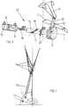
Der vom Fan
Die Größe der Kaltstromfläche
BezugszeichenlisteLIST OF REFERENCE NUMBERS
- 11
- Fanfan
- 22
- Strömungsteilerflow divider
- 33
- Abgaskonusexhaust cone
- 44
- BlütenmischerBloom mixer
- 55
- MischebeneLayers,
- 66
- KaltstromflächeCold flow area
- 77
- HeißstromflächeHot flow area
- 88th
- TriebwerksgondelEngine nacelle
- 99
- rinnenförmige Kanäle von
4 channel-shaped channels of4 - 1010
- Stellstangecontrol rod
- 1111
- Drehscheibeturntable
- 1212
- Öffnung in
3 Opening in3 - 1313
- Steuerstiftcontrol pin
- 14 14
- Druckstangepushrod
- 1515
- Druckzylinderpressure cylinder
- 1616
- Kolbenpiston
- 1717
- Steuerohrhead tube
- 1818
- Steuerschlitzcontrol slot
- 1919
- Führungselementguide element
- 2020
- Haltemittelholding means
- 2121
- Antriebsmitteldrive means
- KK
- KaltluftstromCold air flow
- HH
- Heißluftstrom Drehwinkel von
11 Hot air flow rotation angle of11
ZITATE ENTHALTEN IN DER BESCHREIBUNG QUOTES INCLUDE IN THE DESCRIPTION
Diese Liste der vom Anmelder aufgeführten Dokumente wurde automatisiert erzeugt und ist ausschließlich zur besseren Information des Lesers aufgenommen. Die Liste ist nicht Bestandteil der deutschen Patent- bzw. Gebrauchsmusteranmeldung. Das DPMA übernimmt keinerlei Haftung für etwaige Fehler oder Auslassungen.This list of the documents listed by the applicant has been generated automatically and is included solely for the better information of the reader. The list is not part of the German patent or utility model application. The DPMA assumes no liability for any errors or omissions.
Zitierte PatentliteraturCited patent literature
- US 5771681[0005]US 5771681[0005]
Claims (5)
Translated fromGermanPriority Applications (1)
| Application Number | Priority Date | Filing Date | Title |
|---|---|---|---|
| DE102010014910ADE102010014910A1 (en) | 2010-04-14 | 2010-04-14 | Mixing device for turbofan engine for mixing cold air stream with hot-air stream, has engine pod and exhaust cone that defines cold air stream with hot-air stream |
Applications Claiming Priority (1)
| Application Number | Priority Date | Filing Date | Title |
|---|---|---|---|
| DE102010014910ADE102010014910A1 (en) | 2010-04-14 | 2010-04-14 | Mixing device for turbofan engine for mixing cold air stream with hot-air stream, has engine pod and exhaust cone that defines cold air stream with hot-air stream |
Publications (1)
| Publication Number | Publication Date |
|---|---|
| DE102010014910A1true DE102010014910A1 (en) | 2011-10-20 |
Family
ID=44730493
Family Applications (1)
| Application Number | Title | Priority Date | Filing Date |
|---|---|---|---|
| DE102010014910AWithdrawnDE102010014910A1 (en) | 2010-04-14 | 2010-04-14 | Mixing device for turbofan engine for mixing cold air stream with hot-air stream, has engine pod and exhaust cone that defines cold air stream with hot-air stream |
Country Status (1)
| Country | Link |
|---|---|
| DE (1) | DE102010014910A1 (en) |
Cited By (4)
| Publication number | Priority date | Publication date | Assignee | Title |
|---|---|---|---|---|
| FR2996258A1 (en)* | 2012-10-01 | 2014-04-04 | Snecma | ALTERNATIVE ROTATION MIXER FOR A TURBOMACHINE CONFLUENT FLUX TUBE AND ITS STEERING PROCESS |
| EP2787210A1 (en) | 2013-04-04 | 2014-10-08 | MTU Aero Engines GmbH | Mixing device and turbofan engine with such a mixing device |
| CN113006963A (en)* | 2021-04-01 | 2021-06-22 | 南昌航空大学 | Blocking cone for sword-shaped deep trough alternating lobe spray pipe and connection of blocking cone |
| CN115962062A (en)* | 2023-01-09 | 2023-04-14 | 中国航发湖南动力机械研究所 | A lobe mixing nozzle with adjustable bypass ratio and its application method |
Citations (5)
| Publication number | Priority date | Publication date | Assignee | Title |
|---|---|---|---|---|
| US5771681A (en) | 1996-09-17 | 1998-06-30 | The Boeing Company | Aircraft turbofan engine mixing apparatus |
| US5884472A (en)* | 1995-10-11 | 1999-03-23 | Stage Iii Technologies, L.C. | Alternating lobed mixer/ejector concept suppressor |
| US6082635A (en)* | 1996-06-12 | 2000-07-04 | The United States Of America As Represented By The Administrator Of The National Aeronautics And Space Administration | Undulated nozzle for enhanced exit area mixing |
| DE19909792A1 (en)* | 1999-03-05 | 2000-09-07 | Rolls Royce Deutschland | Mixer for twin circuit jet engine, with outward radial channels offset alternately from each other in flow direction |
| US7581384B2 (en)* | 2006-06-26 | 2009-09-01 | Snecma | Turbomachine nozzle cover provided with triangular patterns having a point of inflexion for reducing jet noise |
- 2010
- 2010-04-14DEDE102010014910Apatent/DE102010014910A1/ennot_activeWithdrawn
Patent Citations (5)
| Publication number | Priority date | Publication date | Assignee | Title |
|---|---|---|---|---|
| US5884472A (en)* | 1995-10-11 | 1999-03-23 | Stage Iii Technologies, L.C. | Alternating lobed mixer/ejector concept suppressor |
| US6082635A (en)* | 1996-06-12 | 2000-07-04 | The United States Of America As Represented By The Administrator Of The National Aeronautics And Space Administration | Undulated nozzle for enhanced exit area mixing |
| US5771681A (en) | 1996-09-17 | 1998-06-30 | The Boeing Company | Aircraft turbofan engine mixing apparatus |
| DE19909792A1 (en)* | 1999-03-05 | 2000-09-07 | Rolls Royce Deutschland | Mixer for twin circuit jet engine, with outward radial channels offset alternately from each other in flow direction |
| US7581384B2 (en)* | 2006-06-26 | 2009-09-01 | Snecma | Turbomachine nozzle cover provided with triangular patterns having a point of inflexion for reducing jet noise |
Cited By (10)
| Publication number | Priority date | Publication date | Assignee | Title |
|---|---|---|---|---|
| FR2996258A1 (en)* | 2012-10-01 | 2014-04-04 | Snecma | ALTERNATIVE ROTATION MIXER FOR A TURBOMACHINE CONFLUENT FLUX TUBE AND ITS STEERING PROCESS |
| GB2508699A (en)* | 2012-10-01 | 2014-06-11 | Snecma | Reciprocating nozzle of a gas turbine engine |
| US8881502B2 (en) | 2012-10-01 | 2014-11-11 | Snecma | Mixer that performs reciprocating rotary motion for a confluent-flow nozzle of a turbine engine, and a method of controlling it |
| GB2508699B (en)* | 2012-10-01 | 2019-11-06 | Snecma | A mixer that performs reciprocating rotary motion for a confluent-flow nozzle of a turbine engine, and a method of controlling it |
| EP2787210A1 (en) | 2013-04-04 | 2014-10-08 | MTU Aero Engines GmbH | Mixing device and turbofan engine with such a mixing device |
| DE102013205911A1 (en) | 2013-04-04 | 2014-10-09 | MTU Aero Engines AG | Mixing device and turbofan engine with such a mixing device |
| US9771896B2 (en) | 2013-04-04 | 2017-09-26 | MTU Aero Engines AG | Mixing device and turbofan engine having such mixing device |
| CN113006963A (en)* | 2021-04-01 | 2021-06-22 | 南昌航空大学 | Blocking cone for sword-shaped deep trough alternating lobe spray pipe and connection of blocking cone |
| CN113006963B (en)* | 2021-04-01 | 2022-08-12 | 南昌航空大学 | A plugging cone for sword-shaped deep trough alternating lobe nozzle and its connection |
| CN115962062A (en)* | 2023-01-09 | 2023-04-14 | 中国航发湖南动力机械研究所 | A lobe mixing nozzle with adjustable bypass ratio and its application method |
Similar Documents
| Publication | Publication Date | Title |
|---|---|---|
| EP3388649B1 (en) | Nacelle for a turbofan engine | |
| EP3306066B1 (en) | Turbofan engine for a civil supersonic aircraft | |
| EP2835522B1 (en) | Device and method for letting off compressor air in an engine | |
| EP2167793B1 (en) | Exhaust gas turbocharger for an internal combustion engine | |
| DE2042026A1 (en) | Drive nozzle with sound dampening device | |
| DE2206728A1 (en) | Exhaust nozzle of a power turbine engine | |
| EP2989298B1 (en) | Exhaust gas turbocharger | |
| DE1285328B (en) | Jet engine with jet deflection | |
| EP2824284A1 (en) | Turbofan engine | |
| DE102015209892A1 (en) | Adaptive aircraft engine and aircraft with an adaptive engine | |
| DE866145C (en) | Method and device for starting two-circuit jet engines, in particular for aircraft | |
| EP3366907B1 (en) | Convergent-divergent nozzle for a turbofan engine of a supersonic aircraft and method for adjusting the nozzle throat surface in a nozzle of a turbofan engine | |
| DE102010014910A1 (en) | Mixing device for turbofan engine for mixing cold air stream with hot-air stream, has engine pod and exhaust cone that defines cold air stream with hot-air stream | |
| EP2431599B1 (en) | Lobe mixer for a turbofan engine | |
| DE1601625A1 (en) | Blade actuation mechanism, especially for stator blades in gas turbine jet engines | |
| EP1530671A1 (en) | Exhaust gas turbocharger for an internal combustion engine | |
| EP1964774A2 (en) | Flying device with rotating cylinders for generating lift and/or thrust | |
| DE2617039A1 (en) | REVERSIBLE OR EMPLOYMENT VARIABLES FAN WITH DIVIDED FLOW DIVIDER | |
| EP3075661B1 (en) | Engine cowl of an aircraft gas turbine | |
| DE1119126B (en) | Jet engine with a jet deflector | |
| DE102010014909A1 (en) | Variable mixer i.e. variable bloom mixer, for mixing cool and hot air streams of fan of turbofan engine of aircraft, has traction cable for obtaining original position by compensating traction force using resilient material properties | |
| DE102019125038A1 (en) | Jet engine | |
| DE2114916B2 (en) | ROTATING DEVICE FOR A BLADE RUNNER OF A FLOW MACHINE | |
| DE102022004743A1 (en) | Gas expansion device with flow control device | |
| DE102023129272A1 (en) | Gas turbine for an aircraft |
Legal Events
| Date | Code | Title | Description |
|---|---|---|---|
| R163 | Identified publications notified | ||
| R012 | Request for examination validly filed | ||
| R016 | Response to examination communication | ||
| R082 | Change of representative | ||
| R119 | Application deemed withdrawn, or ip right lapsed, due to non-payment of renewal fee |