DE102010014277A1 - Filter device and main filter element for a filter device - Google Patents
Filter device and main filter element for a filter deviceDownload PDFInfo
- Publication number
- DE102010014277A1 DE102010014277A1DE102010014277ADE102010014277ADE102010014277A1DE 102010014277 A1DE102010014277 A1DE 102010014277A1DE 102010014277 ADE102010014277 ADE 102010014277ADE 102010014277 ADE102010014277 ADE 102010014277ADE 102010014277 A1DE102010014277 A1DE 102010014277A1
- Authority
- DE
- Germany
- Prior art keywords
- filter
- main
- filter element
- filter housing
- housing
- Prior art date
- Legal status (The legal status is an assumption and is not a legal conclusion. Google has not performed a legal analysis and makes no representation as to the accuracy of the status listed.)
- Granted
Links
- 239000002245particleSubstances0.000claimsabstractdescription12
- 239000007788liquidSubstances0.000claimsabstractdescription3
- 239000007787solidSubstances0.000claimsabstractdescription3
- 229920002635polyurethanePolymers0.000claimsdescription13
- 239000004814polyurethaneSubstances0.000claimsdescription13
- 230000002093peripheral effectEffects0.000claimsdescription10
- 238000007789sealingMethods0.000claimsdescription8
- 238000002485combustion reactionMethods0.000claimsdescription6
- 238000011144upstream manufacturingMethods0.000claimsdescription5
- 239000013013elastic materialSubstances0.000claimsdescription4
- 230000001681protective effectEffects0.000claimsdescription2
- 230000000087stabilizing effectEffects0.000claims2
- 238000009434installationMethods0.000claims1
- 230000006641stabilisationEffects0.000abstractdescription2
- 238000011105stabilizationMethods0.000abstractdescription2
- 238000011045prefiltrationMethods0.000abstract1
- 206010000496acneDiseases0.000description5
- 125000006850spacer groupChemical group0.000description2
- BUHVIAUBTBOHAG-FOYDDCNASA-N(2r,3r,4s,5r)-2-[6-[[2-(3,5-dimethoxyphenyl)-2-(2-methylphenyl)ethyl]amino]purin-9-yl]-5-(hydroxymethyl)oxolane-3,4-diolChemical compoundCOC1=CC(OC)=CC(C(CNC=2C=3N=CN(C=3N=CN=2)[C@H]2[C@@H]([C@H](O)[C@@H](CO)O2)O)C=2C(=CC=CC=2)C)=C1BUHVIAUBTBOHAG-FOYDDCNASA-N0.000description1
- 238000004026adhesive bondingMethods0.000description1
- 238000011161developmentMethods0.000description1
- 230000018109developmental processEffects0.000description1
- 238000005516engineering processMethods0.000description1
- 239000012530fluidSubstances0.000description1
- JTJMJGYZQZDUJJ-UHFFFAOYSA-NphencyclidineChemical classC1CCCCN1C1(C=2C=CC=CC=2)CCCCC1JTJMJGYZQZDUJJ-UHFFFAOYSA-N0.000description1
- 230000000284resting effectEffects0.000description1
Images


Classifications
- B—PERFORMING OPERATIONS; TRANSPORTING
- B01—PHYSICAL OR CHEMICAL PROCESSES OR APPARATUS IN GENERAL
- B01D—SEPARATION
- B01D50/00—Combinations of methods or devices for separating particles from gases or vapours
- B—PERFORMING OPERATIONS; TRANSPORTING
- B01—PHYSICAL OR CHEMICAL PROCESSES OR APPARATUS IN GENERAL
- B01D—SEPARATION
- B01D46/00—Filters or filtering processes specially modified for separating dispersed particles from gases or vapours
- B01D46/0002—Casings; Housings; Frame constructions
- B01D46/0005—Mounting of filtering elements within casings, housings or frames
- B—PERFORMING OPERATIONS; TRANSPORTING
- B01—PHYSICAL OR CHEMICAL PROCESSES OR APPARATUS IN GENERAL
- B01D—SEPARATION
- B01D45/00—Separating dispersed particles from gases or vapours by gravity, inertia, or centrifugal forces
- B01D45/12—Separating dispersed particles from gases or vapours by gravity, inertia, or centrifugal forces by centrifugal forces
- B01D45/16—Separating dispersed particles from gases or vapours by gravity, inertia, or centrifugal forces by centrifugal forces generated by the winding course of the gas stream, the centrifugal forces being generated solely or partly by mechanical means, e.g. fixed swirl vanes
- B—PERFORMING OPERATIONS; TRANSPORTING
- B01—PHYSICAL OR CHEMICAL PROCESSES OR APPARATUS IN GENERAL
- B01D—SEPARATION
- B01D46/00—Filters or filtering processes specially modified for separating dispersed particles from gases or vapours
- B—PERFORMING OPERATIONS; TRANSPORTING
- B01—PHYSICAL OR CHEMICAL PROCESSES OR APPARATUS IN GENERAL
- B01D—SEPARATION
- B01D46/00—Filters or filtering processes specially modified for separating dispersed particles from gases or vapours
- B01D46/0002—Casings; Housings; Frame constructions
- B01D46/0004—Details of removable closures, lids, caps or filter heads
- B—PERFORMING OPERATIONS; TRANSPORTING
- B01—PHYSICAL OR CHEMICAL PROCESSES OR APPARATUS IN GENERAL
- B01D—SEPARATION
- B01D46/00—Filters or filtering processes specially modified for separating dispersed particles from gases or vapours
- B01D46/0002—Casings; Housings; Frame constructions
- B01D46/0005—Mounting of filtering elements within casings, housings or frames
- B01D46/0006—Filter elements or cartridges installed in a drawer-like manner
- B—PERFORMING OPERATIONS; TRANSPORTING
- B01—PHYSICAL OR CHEMICAL PROCESSES OR APPARATUS IN GENERAL
- B01D—SEPARATION
- B01D46/00—Filters or filtering processes specially modified for separating dispersed particles from gases or vapours
- B01D46/0002—Casings; Housings; Frame constructions
- B01D46/0013—Modules
- B—PERFORMING OPERATIONS; TRANSPORTING
- B01—PHYSICAL OR CHEMICAL PROCESSES OR APPARATUS IN GENERAL
- B01D—SEPARATION
- B01D46/00—Filters or filtering processes specially modified for separating dispersed particles from gases or vapours
- B01D46/0084—Filters or filtering processes specially modified for separating dispersed particles from gases or vapours provided with safety means
- B01D46/009—Identification of filter type or position thereof, e.g. by transponders or bar codes
- B—PERFORMING OPERATIONS; TRANSPORTING
- B01—PHYSICAL OR CHEMICAL PROCESSES OR APPARATUS IN GENERAL
- B01D—SEPARATION
- B01D46/00—Filters or filtering processes specially modified for separating dispersed particles from gases or vapours
- B01D46/24—Particle separators, e.g. dust precipitators, using rigid hollow filter bodies
- B01D46/2403—Particle separators, e.g. dust precipitators, using rigid hollow filter bodies characterised by the physical shape or structure of the filtering element
- B01D46/2411—Filter cartridges
- B01D46/2414—End caps including additional functions or special forms
- B—PERFORMING OPERATIONS; TRANSPORTING
- B01—PHYSICAL OR CHEMICAL PROCESSES OR APPARATUS IN GENERAL
- B01D—SEPARATION
- B01D46/00—Filters or filtering processes specially modified for separating dispersed particles from gases or vapours
- B01D46/24—Particle separators, e.g. dust precipitators, using rigid hollow filter bodies
- B01D46/2403—Particle separators, e.g. dust precipitators, using rigid hollow filter bodies characterised by the physical shape or structure of the filtering element
- B01D46/2418—Honeycomb filters
- B—PERFORMING OPERATIONS; TRANSPORTING
- B01—PHYSICAL OR CHEMICAL PROCESSES OR APPARATUS IN GENERAL
- B01D—SEPARATION
- B01D46/00—Filters or filtering processes specially modified for separating dispersed particles from gases or vapours
- B01D46/42—Auxiliary equipment or operation thereof
- B—PERFORMING OPERATIONS; TRANSPORTING
- B01—PHYSICAL OR CHEMICAL PROCESSES OR APPARATUS IN GENERAL
- B01D—SEPARATION
- B01D46/00—Filters or filtering processes specially modified for separating dispersed particles from gases or vapours
- B01D46/52—Particle separators, e.g. dust precipitators, using filters embodying folded corrugated or wound sheet material
- B01D46/521—Particle separators, e.g. dust precipitators, using filters embodying folded corrugated or wound sheet material using folded, pleated material
- B01D46/525—Particle separators, e.g. dust precipitators, using filters embodying folded corrugated or wound sheet material using folded, pleated material which comprises flutes
- B—PERFORMING OPERATIONS; TRANSPORTING
- B01—PHYSICAL OR CHEMICAL PROCESSES OR APPARATUS IN GENERAL
- B01D—SEPARATION
- B01D46/00—Filters or filtering processes specially modified for separating dispersed particles from gases or vapours
- B01D46/56—Filters or filtering processes specially modified for separating dispersed particles from gases or vapours with multiple filtering elements, characterised by their mutual disposition
- B01D46/62—Filters or filtering processes specially modified for separating dispersed particles from gases or vapours with multiple filtering elements, characterised by their mutual disposition connected in series
- B—PERFORMING OPERATIONS; TRANSPORTING
- B01—PHYSICAL OR CHEMICAL PROCESSES OR APPARATUS IN GENERAL
- B01D—SEPARATION
- B01D50/00—Combinations of methods or devices for separating particles from gases or vapours
- B01D50/20—Combinations of devices covered by groups B01D45/00 and B01D46/00
- F—MECHANICAL ENGINEERING; LIGHTING; HEATING; WEAPONS; BLASTING
- F02—COMBUSTION ENGINES; HOT-GAS OR COMBUSTION-PRODUCT ENGINE PLANTS
- F02M—SUPPLYING COMBUSTION ENGINES IN GENERAL WITH COMBUSTIBLE MIXTURES OR CONSTITUENTS THEREOF
- F02M35/00—Combustion-air cleaners, air intakes, intake silencers, or induction systems specially adapted for, or arranged on, internal-combustion engines
- F02M35/02—Air cleaners
- F02M35/0201—Housings; Casings; Frame constructions; Lids; Manufacturing or assembling thereof
- F02M35/0202—Manufacturing or assembling; Materials for air cleaner housings
- F02M35/0203—Manufacturing or assembling; Materials for air cleaner housings by using clamps, catches, locks or the like, e.g. for disposable plug-in filter cartridges
- F—MECHANICAL ENGINEERING; LIGHTING; HEATING; WEAPONS; BLASTING
- F02—COMBUSTION ENGINES; HOT-GAS OR COMBUSTION-PRODUCT ENGINE PLANTS
- F02M—SUPPLYING COMBUSTION ENGINES IN GENERAL WITH COMBUSTIBLE MIXTURES OR CONSTITUENTS THEREOF
- F02M35/00—Combustion-air cleaners, air intakes, intake silencers, or induction systems specially adapted for, or arranged on, internal-combustion engines
- F02M35/02—Air cleaners
- F02M35/024—Air cleaners using filters, e.g. moistened
- B—PERFORMING OPERATIONS; TRANSPORTING
- B01—PHYSICAL OR CHEMICAL PROCESSES OR APPARATUS IN GENERAL
- B01D—SEPARATION
- B01D2265/00—Casings, housings or mounting for filters specially adapted for separating dispersed particles from gases or vapours
- B01D2265/02—Non-permanent measures for connecting different parts of the filter
- B01D2265/024—Mounting aids
- B01D2265/025—Mounting aids making use of ramps or cams
- B—PERFORMING OPERATIONS; TRANSPORTING
- B01—PHYSICAL OR CHEMICAL PROCESSES OR APPARATUS IN GENERAL
- B01D—SEPARATION
- B01D2271/00—Sealings for filters specially adapted for separating dispersed particles from gases or vapours
- B01D2271/02—Gaskets, sealings
- B—PERFORMING OPERATIONS; TRANSPORTING
- B01—PHYSICAL OR CHEMICAL PROCESSES OR APPARATUS IN GENERAL
- B01D—SEPARATION
- B01D2271/00—Sealings for filters specially adapted for separating dispersed particles from gases or vapours
- B01D2271/02—Gaskets, sealings
- B01D2271/022—Axial sealings
- B—PERFORMING OPERATIONS; TRANSPORTING
- B01—PHYSICAL OR CHEMICAL PROCESSES OR APPARATUS IN GENERAL
- B01D—SEPARATION
- B01D2275/00—Filter media structures for filters specially adapted for separating dispersed particles from gases or vapours
- B01D2275/20—Shape of filtering material
- B01D2275/208—Oval shape
- B—PERFORMING OPERATIONS; TRANSPORTING
- B01—PHYSICAL OR CHEMICAL PROCESSES OR APPARATUS IN GENERAL
- B01D—SEPARATION
- B01D2279/00—Filters adapted for separating dispersed particles from gases or vapours specially modified for specific uses
- B01D2279/60—Filters adapted for separating dispersed particles from gases or vapours specially modified for specific uses for the intake of internal combustion engines or turbines
- B—PERFORMING OPERATIONS; TRANSPORTING
- B01—PHYSICAL OR CHEMICAL PROCESSES OR APPARATUS IN GENERAL
- B01D—SEPARATION
- B01D46/00—Filters or filtering processes specially modified for separating dispersed particles from gases or vapours
- B01D46/24—Particle separators, e.g. dust precipitators, using rigid hollow filter bodies
- B01D46/2403—Particle separators, e.g. dust precipitators, using rigid hollow filter bodies characterised by the physical shape or structure of the filtering element
- B01D46/2418—Honeycomb filters
- B01D46/2422—Mounting of the body within a housing
Landscapes
- Chemical & Material Sciences (AREA)
- Chemical Kinetics & Catalysis (AREA)
- Engineering & Computer Science (AREA)
- Physics & Mathematics (AREA)
- Geometry (AREA)
- Manufacturing & Machinery (AREA)
- Combustion & Propulsion (AREA)
- Mechanical Engineering (AREA)
- General Engineering & Computer Science (AREA)
- Filtering Of Dispersed Particles In Gases (AREA)
- Lubrication Details And Ventilation Of Internal Combustion Engines (AREA)
Abstract
Translated fromGermanDescription
Translated fromGermanTechnisches GebietTechnical area
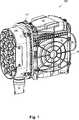
Die Erfindung betrifft eine insbesondere zweistufige Filtervorrichtung zum Abscheiden von flüssigen und/oder festen Partikeln aus einem zu reinigenden Gasstrom, insbesondere einen zweistufigen Luftfilter für eine Brennkraftmaschine, gemäß dem Oberbegriff des Anspruchs 1.The invention relates to a particularly two-stage filter device for separating liquid and / or solid particles from a gas stream to be cleaned, in particular a two-stage air filter for an internal combustion engine, according to the preamble of claim 1.
Stad der TechnikCity of technology
Eine Filtervorrichtung gemäß dem Oberbegriff des Anspruchs 1 ist aus der Druckschrift
Der Erfindung liegt die Aufgabe zugrunde, ein Filterelement der eingangs genannten Art so weiterzubilden, dass das Hauptfilterelement bewegungsfrei im Filtergehäuse angeordnet ist und dass insbesondere ein Herausfallen des Filterelements aus der Filtervorrichtung bei Überkopfmontage verhindert wird.The invention has the object of developing a filter element of the type mentioned so that the main filter element is arranged motionless in the filter housing and that in particular falling out of the filter element is prevented from the filter device in overhead mounting.
Offenbarung der ErfindungDisclosure of the invention
Diese Aufgabe wird durch eine Filtervorrichtung mit den im Anspruch 1 angegebenen Merkmalen gelöst. Vorteilhafte Ausgestaltungen und zweckmäßige Weiterbildungen der vorliegenden Erfindung sind in den Unteransprüchen gekennzeichnet.This object is achieved by a filter device having the features specified in claim 1. Advantageous embodiments and expedient developments of the present invention are characterized in the subclaims.
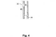
Mithin basiert die vorliegende Erfindung darauf, dass das Hauptfilterelement bzw. Primärelement mindestens ein Halteelement aufweist, das die Lage des Hauptfilterelements im Filtergehäuse stabilisiert. Dieses Halteelement verläuft ausgehend von einer Umfangsseite des Hauptfilterelements in Richtung zum Filtergehäuse und ist dazu ausgebildet, das Hauptfilterelement in definiertem Abstand zum Filtergehäuse anzuordnen. Das Halteelement verhindert somit, dass sich das Hauptfilterelement im Filtergehäuse bewegt.Thus, the present invention is based on the fact that the main filter element or primary element has at least one holding element which stabilizes the position of the main filter element in the filter housing. This holding element extends from a peripheral side of the main filter element in the direction of the filter housing and is adapted to arrange the main filter element at a defined distance from the filter housing. The holding element thus prevents the main filter element from moving in the filter housing.
Vorzugsweise weist das Hauptfilterelement vier an seinen jeweiligen Umfangsseiten angeordnete Halteelemente auf, wobei jeweils zwei dieser Halteelemente sich im Wesentlichen einander gegenüberliegen oder einander schräg gegenüberliegen.Preferably, the main filter element has four holding elements arranged on its respective circumferential sides, wherein in each case two of these holding elements are substantially opposite one another or opposite one another at an angle.
Neben der Stabilisierung des Hauptfilterelements im Filtergehäuse kann das Halteelement auch dazu dienen, ein unerwünschtes Herausfallen des Hauptfilterelements aus dem Filtergehäuse, beispielsweise beim Öffnen des Filtergehäuses, zu verhindern. Zu diesem Zweck weist das Filtergehäuse mindestens eine ausgehend von der Umfangsseite des Filtergehäuses in Richtung zum Hauptfilterelement verlaufende Erhöhung auf, die das Halteelement abstützt und ein selbständiges Herausfallen des Hauptfilterelements aus dem Filtergehäuse verhindert.In addition to the stabilization of the main filter element in the filter housing, the retaining element can also serve to prevent unwanted falling out of the main filter element from the filter housing, for example, when opening the filter housing. For this purpose, the filter housing has at least one extending from the peripheral side of the filter housing in the direction of the main filter element increase, which supports the holding element and prevents an independent falling out of the main filter element from the filter housing.
Damit das Hauptfilterelement auf einfache Weise in das Filtergehäuse eingesetzt bzw. aus diesem entnommen werden kann, ist das Halteelement vorzugsweise aus elastischem Material, beispielsweise aus Polyurethan, gebildet. So kann das Halteelement beispielsweise mit etwas erhöhtem Kraftaufwand über die Erhöhung des Filtergehäuses hinweg bewegt werden.So that the main filter element can be inserted into or removed from the filter housing in a simple manner, the retaining element is preferably formed of elastic material, for example of polyurethane. For example, the holding element can be moved over the increase in the filter housing with a little increased effort.
In einer Ausführungsform ist das Filtergehäuse anströmseitig mit einem Vorbauteil versehen, wobei das Vorbauteil als Zyklonvorabscheider, Schutzgitter, Ansaugkrümmer oder Rohluftleitung ausgebildet ist.In one embodiment, the filter housing is provided on the inflow side with a Vorbauteil, wherein the Vorbauteil is designed as Zyklonvorabscheider, protective grille, intake manifold or blank air line.
In einer vorteilhaften Ausführungsform weist der Zyklonvorabscheider mehrere kleine Einzelzyklone auf. Ein derartiger Vielzellenzyklon oder Multizyklon, der zum Vorreinigen des Gasstroms eine Vielzahl von Leitschaufeln aufweist, die den Gasstrom in Rotation versetzen, ist beispielsweise in der Druckschrift
Als Hauptfilterelement bzw. Primärelement, welches im Filtergehäuse aufgenommen ist, kommt beispielsweise ein Kompaktluftfilter mit einer Vielzahl von im Bereich der einlassseitigen und auslassseitigen Endflächen wechselseitig verschlossenen Kanälen, die durch das Aneinanderlegen einer Glatt- und einer Weltlage gebildet werden, in Betracht, bei dem der Gasstrom linear durch die Filterkanäle geführt wird. Alternativ kann ein Ein- oder Mehrfachbalgfilter mit ringförmig geschlossenen, zick-zack-förmig gefalteten Filterbälgen, vorzugsweise ein Doppelbalgluftfilter mit einem um ein kleineres Ringfilterelement angeordneten, größeren Ringfilterelement, oder ein zick-zack-förmig gefaltetes, ebenes Filterelement verwendet werden.As a main filter element or primary element, which is accommodated in the filter housing, comes for example a compact air filter with a plurality of in the region of the inlet side and outlet end surfaces mutually closed channels, which are formed by the juxtaposition of a smooth and a world situation into consideration, in which the Gas flow is guided linearly through the filter channels. Alternatively, a single or Mehrfachbalgfilter with annularly closed, zig-zag folded filter bellows, preferably a Doppelbalfluftfilter with a arranged around a smaller ring filter element, larger ring filter element, or a zig-zag folded, flat filter element can be used.
Das Filtermedium ist vorzugsweise im Wesentlichen ringförmig oder oval. Beispielsweise kann, wie in der Druckschrift
Kurze Beschreibung der Zeichnungen Brief description of the drawings
Wie bereits vorstehend erörtert, gibt es verschiedene Möglichkeiten, die Lehre der vorliegenden Erfindung in vorteilhafter Weise auszugestalten und weiterzubilden. Hierzu wird einerseits auf die dem Anspruch 1 nachgeordneten Ansprüche verwiesen, andererseits werden weitere Ausgestaltungen, Merkmale und Vorteile der vorliegenden Erfindung nachstehend unter anderem anhand des durch die
Es zeigt:It shows:
Gleiche oder ähnliche Ausgestaltungen, Elemente oder Merkmale sind in den
Ausführungsform(en) der ErfindungEmbodiment (s) of the invention
Bei der in
Das Filtergehäuse
Der Zyklonvorabscheider
In den
ZITATE ENTHALTEN IN DER BESCHREIBUNG QUOTES INCLUDE IN THE DESCRIPTION
Diese Liste der vom Anmelder aufgeführten Dokumente wurde automatisiert erzeugt und ist ausschließlich zur besseren Information des Lesers aufgenommen. Die Liste ist nicht Bestandteil der deutschen Patent- bzw. Gebrauchsmusteranmeldung. Das DPMA übernimmt keinerlei Haftung für etwaige Fehler oder Auslassungen.This list of the documents listed by the applicant has been generated automatically and is included solely for the better information of the reader. The list is not part of the German patent or utility model application. The DPMA assumes no liability for any errors or omissions.
Zitierte PatentliteraturCited patent literature
- DE 102008011186 A1[0002, 0010, 0012]DE 102008011186 A1[0002, 0010, 0012]
- DE 29819335 U1[0002]DE 29819335 U1[0002]
- DE 10330296 A1[0010]DE 10330296 A1[0010]
Claims (12)
Translated fromGermanPriority Applications (8)
| Application Number | Priority Date | Filing Date | Title |
|---|---|---|---|
| DE102010014277.8ADE102010014277B4 (en) | 2009-10-12 | 2010-04-08 | Filter device and main filter element for a filter device |
| JP2012533576AJP5690831B2 (en) | 2009-10-12 | 2010-10-07 | Filter device and main filter element for filter device |
| PCT/EP2010/064980WO2011045225A1 (en) | 2009-10-12 | 2010-10-07 | Filter device and main filter element for a filter device |
| BR112012008479ABR112012008479A2 (en) | 2009-10-12 | 2010-10-07 | filter device and main filter element for a filter device |
| EP10768902AEP2488275A1 (en) | 2009-10-12 | 2010-10-07 | Filter device and main filter element for a filter device |
| CN201080046019.XACN102548634B (en) | 2009-10-12 | 2010-10-07 | Filter device and main filter part for filter device |
| KR1020127008793AKR20120066649A (en) | 2009-10-12 | 2010-10-07 | Filter device and main filter element for a filter device |
| US13/445,835US8657900B2 (en) | 2009-10-12 | 2012-04-12 | Filter device and main filter element for a filter device |
Applications Claiming Priority (3)
| Application Number | Priority Date | Filing Date | Title |
|---|---|---|---|
| DE102009049170.8 | 2009-10-12 | ||
| DE102009049170 | 2009-10-12 | ||
| DE102010014277.8ADE102010014277B4 (en) | 2009-10-12 | 2010-04-08 | Filter device and main filter element for a filter device |
Publications (2)
| Publication Number | Publication Date |
|---|---|
| DE102010014277A1true DE102010014277A1 (en) | 2011-05-05 |
| DE102010014277B4 DE102010014277B4 (en) | 2020-03-12 |
Family
ID=43712254
Family Applications (2)
| Application Number | Title | Priority Date | Filing Date |
|---|---|---|---|
| DE102010014277.8AActiveDE102010014277B4 (en) | 2009-10-12 | 2010-04-08 | Filter device and main filter element for a filter device |
| DE102010047491.6AActiveDE102010047491B4 (en) | 2009-10-12 | 2010-10-06 | Filter insert and filter device |
Family Applications After (1)
| Application Number | Title | Priority Date | Filing Date |
|---|---|---|---|
| DE102010047491.6AActiveDE102010047491B4 (en) | 2009-10-12 | 2010-10-06 | Filter insert and filter device |
Country Status (8)
| Country | Link |
|---|---|
| US (3) | US20110099960A1 (en) |
| EP (2) | EP2488274B1 (en) |
| JP (2) | JP5751719B2 (en) |
| KR (2) | KR101491226B1 (en) |
| CN (2) | CN102574041B (en) |
| BR (2) | BR112012008651B1 (en) |
| DE (2) | DE102010014277B4 (en) |
| WO (2) | WO2011045220A2 (en) |
Cited By (4)
| Publication number | Priority date | Publication date | Assignee | Title |
|---|---|---|---|---|
| DE102012006426A1 (en)* | 2012-03-30 | 2013-10-02 | Mann + Hummel Gmbh | Filter device, in particular air filter |
| DE102015006713A1 (en) | 2015-05-29 | 2016-03-31 | Mann + Hummel Gmbh | Clamping device for bracing a fluid filter element, in particular air filter element in a filter housing and fluid filter |
| WO2016165907A1 (en) | 2015-04-15 | 2016-10-20 | Mann+Hummel Gmbh | Filter element, in particular for gas filtration |
| DE102016001134A1 (en)* | 2016-02-03 | 2017-08-03 | Mann + Hummel Gmbh | Filter housing and filter |
Families Citing this family (46)
| Publication number | Priority date | Publication date | Assignee | Title |
|---|---|---|---|---|
| US8926724B2 (en) | 2008-02-26 | 2015-01-06 | Mann + Hummel Gmbh | Filtering device, in particular air filter |
| DE102010014277B4 (en)* | 2009-10-12 | 2020-03-12 | Mann+Hummel Gmbh | Filter device and main filter element for a filter device |
| EP2726171B1 (en) | 2011-06-30 | 2017-05-17 | Donaldson Company, Inc. | Air/oil separator assemblies |
| USD749641S1 (en)* | 2012-02-08 | 2016-02-16 | Joerg Menssen | Air filter |
| DE102012005731B4 (en) | 2012-03-23 | 2017-07-06 | Mann + Hummel Gmbh | Air filter and filter element of an air filter |
| CN104540573B (en) | 2012-08-22 | 2017-10-24 | 曼·胡默尔有限公司 | Particularly for the filter of gas filtration |
| CN104540571B (en) | 2012-08-22 | 2017-10-24 | 曼·胡默尔有限公司 | Particularly for the filter of gas filtration |
| US9726123B2 (en)* | 2013-06-20 | 2017-08-08 | Mann+Hummel Gmbh | Air filter, filter element and filter housing of an air filter |
| US10753321B2 (en)* | 2013-06-20 | 2020-08-25 | Mann+Hummel Gmbh | Hollow filter element, filter housing, and filter |
| US10239005B2 (en)* | 2013-06-20 | 2019-03-26 | Mann+Hummel Gmbh | Filter housing, hollow filter element and filter |
| EP3013456B1 (en)* | 2013-06-28 | 2020-04-08 | Donaldson Company, Inc. | Filter cartridge for an air cleaner assembly |
| DE102014009706A1 (en)* | 2013-07-12 | 2015-01-15 | Mann + Hummel Gmbh | Filter element with holding surfaces, filter with a filter element and filter housing of a filter |
| DE102014011444A1 (en)* | 2013-09-02 | 2015-03-05 | Mann + Hummel Gmbh | Filter element and filter system with a filter element |
| DE102013014494A1 (en)* | 2013-09-02 | 2015-03-05 | Mann + Hummel Gmbh | Filter system with seal |
| US10226727B2 (en) | 2014-06-03 | 2019-03-12 | Cummins Filtration Ip, Inc. | Filter assembly with cam-lock filter interface |
| EP2962758B1 (en) | 2014-07-01 | 2017-07-19 | ThinXXS Microtechnology AG | Flow cell having a storage space and a transport channel that can be opened at a predetermined breaking point |
| WO2016078787A1 (en) | 2014-11-22 | 2016-05-26 | Mann+Hummel Gmbh | Air filter cartridge and air filter |
| US10532310B2 (en)* | 2014-12-27 | 2020-01-14 | Donaldson Company, Inc. | Filter cartridges; air cleaner assemblies; housings; features; components; and, methods |
| WO2016141097A2 (en)* | 2015-03-02 | 2016-09-09 | Donaldson Company, Inc. | Filter cartridges; air cleaner assemblies; housings; features; components; and, methods |
| KR20160119327A (en)* | 2015-04-02 | 2016-10-13 | (주)라도 | Joining jig for filter module of air cleaning |
| DE102016003454A1 (en)* | 2015-04-10 | 2016-10-13 | Mann + Hummel Gmbh | Filter holder and filter assembly |
| DE102016003456A1 (en)* | 2015-04-10 | 2016-10-13 | Mann + Hummel Gmbh | Filter holder, filter element and filter assembly |
| ES2788505T3 (en)* | 2015-04-10 | 2020-10-21 | Mann & Hummel Gmbh | Filter element and filter arrangement |
| DE102016003455B4 (en) | 2015-04-10 | 2020-08-06 | Mann+Hummel Gmbh | Filter holder and filter arrangement |
| DE102015011662A1 (en)* | 2015-09-11 | 2016-06-30 | Mann + Hummel Gmbh | Clamping device for fluid-tight clamping of a fluid filter element, fluid filter element and fluid filter with such a bracing device |
| JP6434924B2 (en)* | 2016-01-25 | 2018-12-05 | 本田技研工業株式会社 | Air cleaner |
| DE102016001132A1 (en)* | 2016-02-03 | 2017-08-03 | Mann + Hummel Gmbh | Filter element, element frame of a filter element, filter bellows of a filter element, filter housing and filter |
| DE102017001268A1 (en) | 2016-03-03 | 2017-09-07 | Mann + Hummel Gmbh | A filter assembly |
| DE102017001269A1 (en) | 2016-03-03 | 2017-09-07 | Mann + Hummel Gmbh | Filter element and filter assembly |
| DE102016005353A1 (en) | 2016-05-03 | 2017-11-09 | Mann+Hummel Gmbh | Hollow filter element, in particular for gas filtration |
| USD810786S1 (en)* | 2016-06-03 | 2018-02-20 | S&B Filters, Inc. | Particle separator for motor vehicle engine intake |
| EP3548160B1 (en) | 2016-12-01 | 2021-10-06 | Donaldson Company, Inc. | Filter elements, air cleaner assemblies, and methods of use and assembly |
| DE102017005958B3 (en)* | 2017-04-06 | 2018-10-11 | Mann+Hummel Gmbh | filtering device |
| MX2020002137A (en) | 2017-08-31 | 2020-07-20 | Donaldson Co Inc | Filter cartridges; air cleaner assemblies; housings; features; components; and, methods. |
| TWI655026B (en)* | 2018-01-25 | 2019-04-01 | 淳靖股份有限公司 | Axial flow filter with side cover |
| USD884866S1 (en)* | 2018-05-08 | 2020-05-19 | Cummins Filtration Ip, Inc. | Filter element |
| DE102018004041A1 (en) | 2018-05-18 | 2019-11-21 | Mann+Hummel Gmbh | Air filter element with circumferentially protruding clean air seal, filter housing and air filter |
| WO2019219657A1 (en) | 2018-05-18 | 2019-11-21 | Mann+Hummel Gmbh | Cover for a filter system, seal for a cover, and filter system comprising a cover |
| WO2019219646A1 (en) | 2018-05-18 | 2019-11-21 | Mann+Hummel Gmbh | Filter element and filter system having a filter element |
| MA52620A (en) | 2018-05-18 | 2021-05-26 | Mann & Hummel Gmbh | FILTER ELEMENT, FILTRATION SYSTEM EQUIPPED WITH A FILTER ELEMENT AND PROCESS |
| EP3793711B1 (en) | 2018-05-18 | 2022-12-21 | MANN+HUMMEL GmbH | Filter element, and filter system comprising a filter element and a housing |
| WO2019219654A1 (en) | 2018-05-18 | 2019-11-21 | Mann+Hummel Gmbh | Support tube for a filter element, filter element comprising a support tube, and method for producing such a filter element |
| DE102018117995A1 (en) | 2018-07-25 | 2020-01-30 | Mann+Hummel Gmbh | Filter insert for interchangeable installation in a filter housing of a filter for fluid and filter |
| CN109296478B (en)* | 2018-12-11 | 2024-01-09 | 上海弗列加滤清器有限公司 | Air filter |
| CN114251207B (en)* | 2020-09-23 | 2025-08-22 | 上海欧菲滤清器有限公司 | Air filter assembly |
| DE102022119073A1 (en) | 2022-07-29 | 2024-02-01 | Mann+Hummel Gmbh | Filter and clamping wedge for a filter |
Citations (3)
| Publication number | Priority date | Publication date | Assignee | Title |
|---|---|---|---|---|
| DE29819335U1 (en) | 1998-10-30 | 1999-04-15 | Filterwerk Mann & Hummel Gmbh, 71638 Ludwigsburg | Filters for gaseous media with cyclone for pre-separation |
| DE10330296A1 (en) | 2003-07-04 | 2005-02-03 | Mann + Hummel Gmbh | separating |
| DE102008011186A1 (en) | 2008-02-26 | 2009-09-03 | Mann + Hummel Gmbh | Filter device, in particular air filter for an internal combustion engine |
Family Cites Families (30)
| Publication number | Priority date | Publication date | Assignee | Title |
|---|---|---|---|---|
| US4158449A (en) | 1976-12-07 | 1979-06-19 | Pall Corporation | Inlet air cleaner assembly for turbine engines |
| DE19638790A1 (en)* | 1996-09-21 | 1998-03-26 | Mann & Hummel Filter | Air filter |
| US5740774A (en)* | 1996-12-18 | 1998-04-21 | Siemens Electric Limited | Engine induction air system having improved air filter accessibility |
| JPH11132117A (en)* | 1997-08-26 | 1999-05-18 | Tokyo Roki Co Ltd | Air cleaner |
| DE19849089A1 (en) | 1998-10-24 | 2000-04-27 | Mann & Hummel Filter | Filter, especially for combustion engine air, comprises a three-part housing with an air inlet and a clean air outlet, and an inner filter element |
| JP2001329921A (en)* | 2000-03-17 | 2001-11-30 | Toyo Roki Mfg Co Ltd | Air cleaner |
| US7396375B2 (en)* | 2002-05-09 | 2008-07-08 | Donaldson Company, Inc. | Air filter having fluted filter media |
| DE10222800B4 (en) | 2002-05-23 | 2013-06-27 | Mann + Hummel Gmbh | Filter in a filter housing |
| JP2004060600A (en)* | 2002-07-31 | 2004-02-26 | Toyo Roki Mfg Co Ltd | Air cleaner |
| JP4112937B2 (en)* | 2002-10-09 | 2008-07-02 | ダイハツ工業株式会社 | Air cleaner for internal combustion engine |
| KR20050098922A (en)* | 2003-02-11 | 2005-10-12 | 도널드선 컴파니 인코포레이티드 | Air cleaner arrangements; serviceable filter elements;and,method |
| WO2005079954A1 (en)* | 2004-02-17 | 2005-09-01 | Donaldson Company, Inc. | Air cleaner arrangements; serviceable filter elements; and, methods |
| US7905936B2 (en)* | 2004-04-30 | 2011-03-15 | Donaldson Company, Inc. | Filter arrangements; housing; assemblies; and, methods |
| WO2006009766A1 (en)* | 2004-06-18 | 2006-01-26 | Donaldson Company, Inc. | Air cleaner arrangements; serviceable filter cartridge; and, methods |
| EP1986761A2 (en)* | 2006-01-20 | 2008-11-05 | Donaldson Company, Inc. | Air cleaner configured for receipt of various sized filter cartridges; components thereof; and, methods |
| JP4572870B2 (en)* | 2006-05-23 | 2010-11-04 | トヨタ紡織株式会社 | Air cleaner |
| DE102006025232A1 (en)* | 2006-05-29 | 2008-01-10 | Mann + Hummel Gmbh | filter housing |
| US7713321B2 (en)* | 2006-06-22 | 2010-05-11 | Donaldson Company, Inc. | Air cleaner arrangements; components thereof; and, methods |
| EP2444139B1 (en)* | 2006-06-22 | 2019-04-10 | Donaldson Company, Inc. | Air cleaner assembly |
| US7597735B2 (en)* | 2006-12-21 | 2009-10-06 | Cummins Filtration Ip Inc. | Apparatus and system for uniform sealing force in an air filter assembly |
| JP2008248848A (en)* | 2007-03-30 | 2008-10-16 | Denso Corp | Air cleaner for internal combustion engine |
| DE202007013822U1 (en)* | 2007-10-02 | 2009-02-19 | Mann+Hummel Gmbh | Filter element and filter system |
| DE102008062955A1 (en)* | 2008-12-23 | 2010-07-01 | Mann + Hummel Gmbh | Air filter for internal combustion engine of vehicle, has prefractionator with cyclones comprising flow path, where part of cyclones is aligned with flow path on line corresponding to inflow channel of filter element |
| BRPI0908535A2 (en)* | 2008-02-26 | 2019-09-24 | Mann & Hummel Gmbh | seal configuration |
| WO2009106588A1 (en)* | 2008-02-26 | 2009-09-03 | Mann+Hummel Gmbh | Filter device, in particular air filter for an internal combustion engine |
| WO2009106592A2 (en)* | 2008-02-26 | 2009-09-03 | Mann+Hummel Gmbh | Filter element comprising an optimised bellow-type arrangement |
| EP2829309A1 (en)* | 2008-02-26 | 2015-01-28 | Mann + Hummel Gmbh | Multiple bellows filter with increased efficiency |
| EP2247362B1 (en)* | 2008-02-26 | 2014-04-23 | Mann + Hummel GmbH | Air filter comprising a prefractionator |
| DE102010014277B4 (en)* | 2009-10-12 | 2020-03-12 | Mann+Hummel Gmbh | Filter device and main filter element for a filter device |
| US8409317B2 (en)* | 2009-10-13 | 2013-04-02 | Cummins Filtration Ip Inc. | Filter assembly with housing structure |
- 2010
- 2010-04-08DEDE102010014277.8Apatent/DE102010014277B4/enactiveActive
- 2010-10-06EPEP10768899.6Apatent/EP2488274B1/enactiveActive
- 2010-10-06JPJP2012533575Apatent/JP5751719B2/enactiveActive
- 2010-10-06BRBR112012008651-0Apatent/BR112012008651B1/enactiveIP Right Grant
- 2010-10-06DEDE102010047491.6Apatent/DE102010047491B4/enactiveActive
- 2010-10-06KRKR1020127008600Apatent/KR101491226B1/ennot_activeExpired - Fee Related
- 2010-10-06WOPCT/EP2010/064930patent/WO2011045220A2/enactiveApplication Filing
- 2010-10-06CNCN201080046863.2Apatent/CN102574041B/enactiveActive
- 2010-10-07CNCN201080046019.XApatent/CN102548634B/enactiveActive
- 2010-10-07EPEP10768902Apatent/EP2488275A1/ennot_activeWithdrawn
- 2010-10-07KRKR1020127008793Apatent/KR20120066649A/ennot_activeCeased
- 2010-10-07JPJP2012533576Apatent/JP5690831B2/ennot_activeExpired - Fee Related
- 2010-10-07BRBR112012008479Apatent/BR112012008479A2/ennot_activeIP Right Cessation
- 2010-10-07WOPCT/EP2010/064980patent/WO2011045225A1/enactiveApplication Filing
- 2010-10-12USUS12/902,806patent/US20110099960A1/ennot_activeAbandoned
- 2012
- 2012-04-12USUS13/445,325patent/US9108132B2/enactiveActive
- 2012-04-12USUS13/445,835patent/US8657900B2/ennot_activeExpired - Fee Related
Patent Citations (3)
| Publication number | Priority date | Publication date | Assignee | Title |
|---|---|---|---|---|
| DE29819335U1 (en) | 1998-10-30 | 1999-04-15 | Filterwerk Mann & Hummel Gmbh, 71638 Ludwigsburg | Filters for gaseous media with cyclone for pre-separation |
| DE10330296A1 (en) | 2003-07-04 | 2005-02-03 | Mann + Hummel Gmbh | separating |
| DE102008011186A1 (en) | 2008-02-26 | 2009-09-03 | Mann + Hummel Gmbh | Filter device, in particular air filter for an internal combustion engine |
Cited By (8)
| Publication number | Priority date | Publication date | Assignee | Title |
|---|---|---|---|---|
| DE102012006426A1 (en)* | 2012-03-30 | 2013-10-02 | Mann + Hummel Gmbh | Filter device, in particular air filter |
| WO2016165907A1 (en) | 2015-04-15 | 2016-10-20 | Mann+Hummel Gmbh | Filter element, in particular for gas filtration |
| DE102015004645A1 (en) | 2015-04-15 | 2016-10-20 | Mann + Hummel Gmbh | Filter element, in particular for gas filtration |
| DE102015006713A1 (en) | 2015-05-29 | 2016-03-31 | Mann + Hummel Gmbh | Clamping device for bracing a fluid filter element, in particular air filter element in a filter housing and fluid filter |
| DE102016001134A1 (en)* | 2016-02-03 | 2017-08-03 | Mann + Hummel Gmbh | Filter housing and filter |
| WO2017133798A1 (en)* | 2016-02-03 | 2017-08-10 | Mann+Hummel Gmbh | Filter housing and filter |
| CN108602004A (en)* | 2016-02-03 | 2018-09-28 | 曼·胡默尔有限公司 | Filter housing and filter |
| CN108602004B (en)* | 2016-02-03 | 2021-04-20 | 曼·胡默尔有限公司 | Filter housing and filter |
Also Published As
| Publication number | Publication date |
|---|---|
| KR20120066649A (en) | 2012-06-22 |
| DE102010014277B4 (en) | 2020-03-12 |
| US20110099960A1 (en) | 2011-05-05 |
| CN102548634B (en) | 2015-09-30 |
| JP5751719B2 (en) | 2015-07-22 |
| JP2013507569A (en) | 2013-03-04 |
| BR112012008651A2 (en) | 2017-06-13 |
| WO2011045220A3 (en) | 2011-07-21 |
| EP2488275A1 (en) | 2012-08-22 |
| EP2488274A2 (en) | 2012-08-22 |
| US20130152526A1 (en) | 2013-06-20 |
| US20120198802A1 (en) | 2012-08-09 |
| KR101491226B1 (en) | 2015-02-06 |
| WO2011045225A1 (en) | 2011-04-21 |
| CN102548634A (en) | 2012-07-04 |
| EP2488274B1 (en) | 2016-11-30 |
| DE102010047491A1 (en) | 2011-04-21 |
| KR20120062868A (en) | 2012-06-14 |
| WO2011045220A2 (en) | 2011-04-21 |
| DE102010047491B4 (en) | 2015-10-08 |
| US8657900B2 (en) | 2014-02-25 |
| JP2013507570A (en) | 2013-03-04 |
| US9108132B2 (en) | 2015-08-18 |
| BR112012008479A2 (en) | 2017-06-13 |
| CN102574041B (en) | 2015-01-14 |
| BR112012008651B1 (en) | 2019-06-11 |
| CN102574041A (en) | 2012-07-11 |
| JP5690831B2 (en) | 2015-03-25 |
Similar Documents
| Publication | Publication Date | Title |
|---|---|---|
| DE102010014277A1 (en) | Filter device and main filter element for a filter device | |
| EP2675547B1 (en) | Air filter element, air filter housing, and air filter system | |
| EP2254680B1 (en) | Filter device, in particular air filter for an internal combustion engine | |
| EP2532408B1 (en) | Air filter comprising a prefractionator | |
| EP2878354A1 (en) | Filter device, especially air filter for an internal combustion engine | |
| WO2009106589A1 (en) | Multiple bellow-type filter with increased efficiency | |
| EP2555848A1 (en) | Cyclone separator | |
| DE102016003455A1 (en) | Filter holder, filter element and filter assembly | |
| DE102016003454A1 (en) | Filter holder and filter assembly | |
| DE102014000914A1 (en) | filter element | |
| DE102013018201A1 (en) | Filter insert and air filter | |
| DE102014008704B3 (en) | Filter with an obliquely flowed through filter element | |
| WO2025108671A1 (en) | Filter element, in particular for gas filtration | |
| DE102008062954B4 (en) | Filter device, in particular air filter for an internal combustion engine | |
| DE102014008699B4 (en) | Filter element with prismatic basic shape and filter | |
| DE102014008701B4 (en) | Filter with variable outflow direction | |
| DE202014004897U1 (en) | Filter with variable outflow direction | |
| DE102022129489A1 (en) | Filter device | |
| DE102021118700B4 (en) | Secondary filter element and filter system | |
| DE202018000744U1 (en) | Air filter with low pressure loss | |
| DE10309660A1 (en) | Fluted media air filter separating solids from airflow, includes channels decreasing from maximum opening area at one end, to near-zero at other end | |
| DE102024101713A1 (en) | Flat filter element with an inner and outer filter medium body arrangement | |
| DE102015007653A1 (en) | Filter element with prismatic basic shape | |
| DE102015003754A1 (en) | cyclone | |
| EP3743190A1 (en) | Filter element, in particular for gas filtration |
Legal Events
| Date | Code | Title | Description |
|---|---|---|---|
| OP8 | Request for examination as to paragraph 44 patent law | ||
| R016 | Response to examination communication | ||
| R016 | Response to examination communication | ||
| R081 | Change of applicant/patentee | Owner name:MANN+HUMMEL GMBH, DE Free format text:FORMER OWNER: MANN + HUMMEL GMBH, 71638 LUDWIGSBURG, DE | |
| R016 | Response to examination communication | ||
| R018 | Grant decision by examination section/examining division | ||
| R020 | Patent grant now final |