DE102010009268A1 - Filter element and filter device - Google Patents
Filter element and filter deviceDownload PDFInfo
- Publication number
- DE102010009268A1 DE102010009268A1DE102010009268ADE102010009268ADE102010009268A1DE 102010009268 A1DE102010009268 A1DE 102010009268A1DE 102010009268 ADE102010009268 ADE 102010009268ADE 102010009268 ADE102010009268 ADE 102010009268ADE 102010009268 A1DE102010009268 A1DE 102010009268A1
- Authority
- DE
- Germany
- Prior art keywords
- filter
- filter element
- inner frame
- end plate
- radial
- Prior art date
- Legal status (The legal status is an assumption and is not a legal conclusion. Google has not performed a legal analysis and makes no representation as to the accuracy of the status listed.)
- Withdrawn
Links
- 239000000463materialSubstances0.000claimsabstractdescription20
- 238000002485combustion reactionMethods0.000claimsabstractdescription6
- 238000007789sealingMethods0.000claimsdescription22
- 230000037431insertionEffects0.000claimsdescription4
- 238000003780insertionMethods0.000claimsdescription4
- 230000000694effectsEffects0.000description6
- 239000003566sealing materialSubstances0.000description6
- 238000010276constructionMethods0.000description2
- 230000001419dependent effectEffects0.000description2
- 238000005187foamingMethods0.000description2
- BUHVIAUBTBOHAG-FOYDDCNASA-N(2r,3r,4s,5r)-2-[6-[[2-(3,5-dimethoxyphenyl)-2-(2-methylphenyl)ethyl]amino]purin-9-yl]-5-(hydroxymethyl)oxolane-3,4-diolChemical compoundCOC1=CC(OC)=CC(C(CNC=2C=3N=CN(C=3N=CN=2)[C@H]2[C@@H]([C@H](O)[C@@H](CO)O2)O)C=2C(=CC=CC=2)C)=C1BUHVIAUBTBOHAG-FOYDDCNASA-N0.000description1
- TVEXGJYMHHTVKP-UHFFFAOYSA-N6-oxabicyclo[3.2.1]oct-3-en-7-oneChemical compoundC1C2C(=O)OC1C=CC2TVEXGJYMHHTVKP-UHFFFAOYSA-N0.000description1
- 229920005830Polyurethane FoamPolymers0.000description1
- 230000009471actionEffects0.000description1
- 239000006261foam materialSubstances0.000description1
- 238000001746injection mouldingMethods0.000description1
- 230000010354integrationEffects0.000description1
- 238000002955isolationMethods0.000description1
- 238000004519manufacturing processMethods0.000description1
- 230000009467reductionEffects0.000description1
- 238000000926separation methodMethods0.000description1
- 230000007704transitionEffects0.000description1
Images
Classifications
- B—PERFORMING OPERATIONS; TRANSPORTING
- B01—PHYSICAL OR CHEMICAL PROCESSES OR APPARATUS IN GENERAL
- B01D—SEPARATION
- B01D46/00—Filters or filtering processes specially modified for separating dispersed particles from gases or vapours
- B01D46/24—Particle separators, e.g. dust precipitators, using rigid hollow filter bodies
- B01D46/2403—Particle separators, e.g. dust precipitators, using rigid hollow filter bodies characterised by the physical shape or structure of the filtering element
- B01D46/2411—Filter cartridges
- B01D46/2414—End caps including additional functions or special forms
- F—MECHANICAL ENGINEERING; LIGHTING; HEATING; WEAPONS; BLASTING
- F02—COMBUSTION ENGINES; HOT-GAS OR COMBUSTION-PRODUCT ENGINE PLANTS
- F02M—SUPPLYING COMBUSTION ENGINES IN GENERAL WITH COMBUSTIBLE MIXTURES OR CONSTITUENTS THEREOF
- F02M35/00—Combustion-air cleaners, air intakes, intake silencers, or induction systems specially adapted for, or arranged on, internal-combustion engines
- F02M35/02—Air cleaners
- F02M35/0201—Housings; Casings; Frame constructions; Lids; Manufacturing or assembling thereof
- F02M35/0202—Manufacturing or assembling; Materials for air cleaner housings
- F02M35/0203—Manufacturing or assembling; Materials for air cleaner housings by using clamps, catches, locks or the like, e.g. for disposable plug-in filter cartridges
- F—MECHANICAL ENGINEERING; LIGHTING; HEATING; WEAPONS; BLASTING
- F02—COMBUSTION ENGINES; HOT-GAS OR COMBUSTION-PRODUCT ENGINE PLANTS
- F02M—SUPPLYING COMBUSTION ENGINES IN GENERAL WITH COMBUSTIBLE MIXTURES OR CONSTITUENTS THEREOF
- F02M35/00—Combustion-air cleaners, air intakes, intake silencers, or induction systems specially adapted for, or arranged on, internal-combustion engines
- F02M35/02—Air cleaners
- F02M35/024—Air cleaners using filters, e.g. moistened
- B—PERFORMING OPERATIONS; TRANSPORTING
- B01—PHYSICAL OR CHEMICAL PROCESSES OR APPARATUS IN GENERAL
- B01D—SEPARATION
- B01D2265/00—Casings, housings or mounting for filters specially adapted for separating dispersed particles from gases or vapours
- B01D2265/06—Details of supporting structures for filtering material, e.g. cores
- B—PERFORMING OPERATIONS; TRANSPORTING
- B01—PHYSICAL OR CHEMICAL PROCESSES OR APPARATUS IN GENERAL
- B01D—SEPARATION
- B01D2271/00—Sealings for filters specially adapted for separating dispersed particles from gases or vapours
- B01D2271/02—Gaskets, sealings
- B01D2271/027—Radial sealings
Landscapes
- Engineering & Computer Science (AREA)
- Chemical & Material Sciences (AREA)
- Manufacturing & Machinery (AREA)
- Combustion & Propulsion (AREA)
- Mechanical Engineering (AREA)
- General Engineering & Computer Science (AREA)
- Physics & Mathematics (AREA)
- Geometry (AREA)
- Chemical Kinetics & Catalysis (AREA)
- Filtering Of Dispersed Particles In Gases (AREA)
Abstract
Translated fromGermanDescription
Translated fromGermanDie vorliegende Erfindung betrifft ein Filterelement, insbesondere für ein Luftfilter einer Frischluftanlage eines Fahrzeugs bzw. einer Brennkraftmaschine. Die Erfindung betrifft außerdem eine Filtereinrichtung, insbesondere ein Luftfilter einer Frischluftanlage eines Kraftfahrzeugs bzw. einer Brennkraftmaschine, die mit wenigstens einem solchen Filterelement ausgestattet ist.The present invention relates to a filter element, in particular for an air filter of a fresh air system of a vehicle or an internal combustion engine. The invention also relates to a filter device, in particular an air filter of a fresh air system of a motor vehicle or an internal combustion engine, which is equipped with at least one such filter element.
Aus der
Aus der
Aus der
Problematisch bei derartigen Filterelementen bzw. Filtereinrichtungen ist die gasdichte Verbindung zwischen dem vom Filterkörper umschlossenen Innenraum und einem gehäuseseitigen Anschluss durch bzw. über die jeweilige Endscheibe. Sofern ein Stutzen durch die Scheibenöffnung der jeweiligen Endscheibe eingesteckt wird, kann sich ein die Scheibenöffnung einfassender Öffnungsrand an den jeweiligen Stutzen radial dichtend anlegen. Gleichzeitig wird dadurch auch eine Positionierung des Filterelements am Filtergehäuse erreicht. Es hat sich jedoch gezeigt, dass im Betrieb, insbesondere im Fahrzeugbetrieb, Erschütterungen bzw. Schwingungen auftreten, die zu Relativbewegungen zwischen Filterelement und Filtergehäuse führen, wodurch die Verbindung zwischen Filterelement und Filtergehäuse hohen Belastungen ausgesetzt ist. Dies kann zu einem erhöhten Verschleiß des Filterelements im Bereich der Endscheibe führen. Insbesondere kann die Dichtungswirkung zwischen Endscheibe und Stutzen nachlassen.The problem with such filter elements or filter devices is the gas-tight connection between the enclosed by the filter body interior and a housing-side connection through or over the respective end plate. If a connecting piece is inserted through the disk opening of the respective end disk, an opening edge enclosing the disk opening can be applied in a radially sealing manner to the respective connecting piece. At the same time, this also achieves positioning of the filter element on the filter housing. However, it has been found that during operation, especially in vehicle operation, vibrations or vibrations occur, which lead to relative movements between the filter element and filter housing, whereby the connection between the filter element and the filter housing is exposed to high loads. This can lead to increased wear of the filter element in the region of the end plate. In particular, the sealing effect between the end plate and the neck can be reduced.
Die vorliegende Erfindung beschäftigt sich mit dem Problem, für ein Filterelement bzw. für eine damit ausgestattete Filtereinrichtung eine verbesserte Ausführungsform anzugeben, die sich insbesondere dadurch auszeichnet, dass die Positionierung des Filterelements im Filtergehäuse verbessert ist und/oder dass die Gefahr eines Verschleißes des Filterelements reduziert ist und/oder dass die Dichtungswirkung zwischen der jeweiligen Endscheibe des Filterelements und dem jeweiligen Stutzen des Filtergehäuses verbessert ist.The present invention is concerned with the problem of providing for a filter element or for a filter device equipped therewith an improved embodiment, which is particularly characterized in that the positioning of the filter element is improved in the filter housing and / or reduces the risk of wear of the filter element is and / or that the sealing effect between the respective end plate of the filter element and the respective neck of the filter housing is improved.
Dieses Problem wird erfindungsgemäß durch die Gegenstände der unabhängigen Ansprüche gelöst. Vorteilhafte Ausführungsformen sind Gegenstand der abhängigen Ansprüche.This problem is solved according to the invention by the subject matters of the independent claims. Advantageous embodiments are the subject of the dependent claims.
Die Erfindung beruht auf dem allgemeinen Gedanken, zum einen die Endscheibe mit einer koaxial zur Scheibenöffnung angeordneten Radialdichtung auszustatten und zum anderen die Innenzarge mit mehreren nach innen abstehenden, in Umfangsrichtung verteilt angeordneten radialen Zentrierelementen zu versehen. Diese Zentrierelemente enden radial innen an einer die Scheibenöffnung umschließenden Innenwand der Endscheibe. Folglich sind die radialen Zentrierelemente radial innen bündig in die Innenwand der Endscheibe eingebettet. Die hier vorgeschlagene Bauweise führt zu einer funktionellen Trennung der mit Hilfe der Radialdichtung realisierbaren Dichtungswirkung von der mit Hilfe der radialen Zentrierelemente realisierbaren Zentrierwirkung. Hierdurch werden diese Funktionen voneinander entkoppelt, wodurch die Effektivität der einzelnen Funktionalität verbessert werden kann. Die Zentrierung des Filterelements im Bereich seiner Endscheibe am gehäuseseitigen Stutzen erfolgt über die radialen Zentrierelemente, also über die Innenzarge, die üblicherweise aus einem Zargenmaterial besteht, dessen Steifigkeit größer ist als die Steifigkeit des Scheibenmaterials oder des Filtermaterials. Hierdurch ergibt sich eine stabile, zentrierte Abstützung der Innenzarge über deren radiale Zentrierelemente und somit des Filterelements im Bereich der zugehörigen Endscheibe am jeweiligen, in die Scheibenöffnung besagter Endscheibe eingesteckten, gehäuseseitigen Stutzen. Im Unterschied dazu besteht die Radialdichtung zweckmäßig aus einem Dichtungsmaterial bzw. aus dem Scheibenmaterial, falls die Radialdichtung integral an der Endscheibe ausgeformt ist. Das Dichtungsmaterial bzw. das Scheibenmaterial ist vergleichsweise elastisch bzw. biegeweich, jedenfalls weicher als das Zargenmaterial und kann somit die gewünschte Dichtungsfunktion realisieren. Insbesondere kann die Radialdichtung beim Einstecken des jeweiligen Stutzens elastisch gedehnt werden, so dass die Radialdichtung schließlich unter radialer Vorspannung radial dichtend am jeweiligen Stutzen zur Anlage kommt.The invention is based on the general idea, on the one hand to equip the end plate with a coaxial with the disc opening arranged radial seal and on the other hand to provide the inner frame with a plurality of inwardly projecting, distributed in the circumferential direction arranged radially centering. These centering elements end radially inward on an inner wall of the end disk enclosing the disk opening. Consequently, the radial centering elements are embedded radially flush inside the inner wall of the end plate. The construction proposed here leads to a functional separation of the sealing effect which can be realized with the aid of the radial seal from the centering effect which can be achieved with the aid of the radial centering elements. As a result, these functions are decoupled from each other, whereby the effectiveness of each functionality can be improved. The centering of the filter element in the region of its end plate on the housing-side nozzle via the radial centering, ie via the inner frame, which usually consists of a Zargenmaterial whose rigidity is greater than the stiffness of the disc material or the filter material. This results in a stable, centered support of the inner frame via the radial centering and thus of the filter element in the region of the associated end plate at the respective, inserted into the disc opening end plate, housing-side nozzle. In contrast, the radial seal expediently consists of a sealing material or of the disc material, if the Radial seal is integrally formed on the end plate. The sealing material or the disc material is comparatively elastic or flexible, in any case softer than the frame material and can thus realize the desired sealing function. In particular, the radial seal can be stretched elastically upon insertion of the respective nozzle, so that the radial seal finally comes under radial prestress radial sealing at the respective nozzle to the plant.
Die vorgeschlagene Bauweise führt zu einer signifikanten Reduzierung der Bauteilbelastung, was die Gefahr einer Beschädigung reduziert. Gleichzeitig wird die Dichtungswirkung verbessert.The proposed construction leads to a significant reduction of the component load, which reduces the risk of damage. At the same time the sealing effect is improved.
Entsprechend einer bevorzugten Ausführungsform weist die Innenzarge eine koaxial zur Scheibenöffnung angeordnete Zargenöffnung auf, wobei die radialen Zentrierelemente im Bereich dieser Zargenöffnung ausgehen können. Besonders zweckmäßig ist dabei eine Ausführungsform, bei der die Innenzarge einen Innenrand besitzt, der die zuvor genannte Zargenöffnung umschließt und von dem die radialen Zentrierelemente ausgehen. Hierdurch wird eine sternförmige Anordnung der radialen Zentrierelemente vereinfacht.According to a preferred embodiment, the inner frame has a frame opening arranged coaxially with the disk opening, wherein the radial centering elements can extend in the region of this frame opening. Particularly useful is an embodiment in which the inner frame has an inner edge which encloses the aforementioned Zargenöffnung and emanating from the radial centering. As a result, a star-shaped arrangement of the radial centering is simplified.
Besonders vorteilhaft ist nun eine Ausführungsform, bei welcher die Innenzarge einen scheibenförmigen, axialen Endabschnitt aufweist, der zentral die Zargenöffnung enthält. Durch den scheibenförmigen axialen Endabschnitt erhält die Innenzarge im Bereich der Endscheibe eine signifikant vergrößerte Stabilität, wodurch es insbesondere möglich ist, eine Tragfunktion von der Endscheibe auf die Innenzarge zu verlagern. Hierdurch wird die Herstellung der Endscheibe aus einem Dichtungsmaterial, insbesondere aus einem Schaummaterial, vereinfacht, was die Dichtungsfunktion der Endscheibe verbessert. Die Dichtungsfunktion der Endscheibe betrifft zum einen die axiale Abdichtung des Filtermaterials des Filterkörpers. Sie kann zum anderen optional auch die Realisierung der Radialdichtung betreffen.Particularly advantageous is now an embodiment in which the inner frame has a disc-shaped, axial end portion which centrally contains the frame opening. Due to the disc-shaped axial end section, the inner frame receives in the region of the end plate a significantly increased stability, whereby it is particularly possible to shift a supporting function of the end plate on the inner frame. As a result, the production of the end plate of a sealing material, in particular of a foam material, simplified, which improves the sealing function of the end plate. The sealing function of the end plate relates firstly to the axial sealing of the filter material of the filter body. On the other hand, it can optionally also relate to the realization of the radial seal.
Bei einer anderen vorteilhaften Ausführungsform kann an der Endscheibe eine Stutzenaufnahme zum axialen Einführen eines Stutzens ausgebildet sein. Diese Stutzenaufnahme kann die Scheibenöffnung bilden und die Innenwand sowie die Radialdichtung aufweisen. Zweckmäßig kann besagte Stutzenaufnahme integral an der Endscheibe ausgeformt sein.In another advantageous embodiment, a nozzle receptacle for the axial insertion of a nozzle can be formed on the end plate. This nozzle holder can form the disc opening and have the inner wall and the radial seal. Appropriately, said nozzle receptacle can be integrally formed on the end plate.
Um die Positionierung des Filterelements im Filtergehäuse weiter verbessern bzw. stabilisieren zu können, kann die Innenzarge optional mehrere in Umfangsrichtung verteilt angeordnete, nach außen abstehende axiale Zentrierelemente aufweisen, die axial außen an einer Außenseite der Endscheibe enden.In order to be able to further improve or stabilize the positioning of the filter element in the filter housing, the inner frame can optionally have a plurality of circumferentially distributed, outwardly projecting axial centering elements which terminate axially outwardly on an outer side of the end plate.
Die radialen Zentrierelemente und/oder die axialen Zentrierelemente können bevorzugt weitgehend in die Endscheibe eingebettet sein. Zweckmäßig sind sie im Wesentlichen vollständig in die Endscheibe eingebettet. Besonders vorteilhaft ist eine Ausführungsform, bei der das jeweilige Zentrierelement nur noch mit seinem mit Bezug auf die übrige Innenzarge distalen stirnseitigen Ende sichtbar ist bzw. nicht vom Scheibenmaterial bedeckt ist und dort insbesondere bündig zur Endscheibe verläuft bzw. endet.The radial centering elements and / or the axial centering elements may preferably be largely embedded in the end plate. Suitably, they are substantially completely embedded in the end plate. Particularly advantageous is an embodiment in which the respective centering is visible only with its with respect to the rest of the inner frame distal end face or is not covered by the disc material and runs there in particular flush with the end plate and ends.
Die radialen Zentrierelemente besitzen bezogen auf eine Längsmittelachse des Filterelements eine radiale Dimension. Besonders vorteilhaft ist eine Ausführungsform, bei der sich die radialen Zentrierelemente bezüglich der Längsmittelachse des Filterelements radial nach innen erstrecken. Entsprechendes gilt auch für die axialen Zentrierelemente, die eine parallel zur Längsachse des Filterelements verlaufende axiale Dimension besitzen. Bevorzugt ist jedoch hier eine Ausführungsform, bei welcher sich die axialen Zentrierelemente axial erstrecken, so dass sie parallel zur Längsachse des Filterelements verlaufen.The radial centering elements have a radial dimension relative to a longitudinal central axis of the filter element. Particularly advantageous is an embodiment in which the radial centering elements extend radially inwardly with respect to the longitudinal central axis of the filter element. The same applies to the axial centering elements, which have a parallel to the longitudinal axis of the filter element extending axial dimension. However, an embodiment in which the axial centering elements extend axially so that they run parallel to the longitudinal axis of the filter element is preferred.
Mit Hilfe eines Deckels zum Verschließen des Aufnahmeraums, der einen ebenfalls mit einer Endscheibe des Filterelements zusammenwirkenden Stutzen aufweist, kann eine Montagehilfe und Zentrierhilfe für das Filterelement bereitgestellt werden.With the help of a lid for closing the receiving space, which also has a cooperating with an end plate of the filter element nozzle, an assembly aid and centering aid for the filter element can be provided.
Weitere wichtige Merkmale und Vorteile der Erfindung ergeben sich aus den Unteransprüchen, aus den Zeichnungen und aus der zugehörigen Figurenbeschreibung anhand der Zeichnungen.Other important features and advantages of the invention will become apparent from the dependent claims, from the drawings and from the associated figure description with reference to the drawings.
Es versteht sich, dass die vorstehend genannten und die nachstehend noch zu erläuternden Merkmale nicht nur in der jeweils angegebenen Kombination, sondern auch in anderen Kombinationen oder in Alleinstellung verwendbar sind, ohne den Rahmen der vorliegenden Erfindung zu verlassen.It is understood that the features mentioned above and those yet to be explained below can be used not only in the particular combination given, but also in other combinations or in isolation, without departing from the scope of the present invention.
Bevorzugte Ausführungsbeispiele der Erfindung sind in den Zeichnungen dargestellt und werden in der nachfolgenden Beschreibung näher erläutert, wobei sich gleiche Bezugszeichen auf gleiche oder ähnliche oder funktional gleiche Bauteile beziehen.Preferred embodiments of the invention are illustrated in the drawings and will be described in more detail in the following description, wherein like reference numerals refer to the same or similar or functionally identical components.
Es zeigen, jeweils schematisch,Show, in each case schematically,
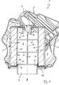
Entsprechend
Das Filtergehäuse
Der Sekundärauslass
Das Filterelement
Das Filterelement
Ferner weist das Filterelement
Die dem Sekundärauslass
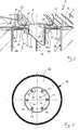
Die Innenzarge
Die Zargenöffnung
Zweckmäßig besitzt die Innenzarge
An der dem Sekundärauslass
Gemäß
Auch für die axialen Zentrierelemente
Bei den hier gezeigten Ausführungsformen sind die Zentrierelemente
Die inneren axialen Zentrierelemente
Entsprechend
Die Radialdichtung
Die Endscheibe
Entsprechend
Durch die Positionierung des Filterelements
ZITATE ENTHALTEN IN DER BESCHREIBUNG QUOTES INCLUDE IN THE DESCRIPTION
Diese Liste der vom Anmelder aufgeführten Dokumente wurde automatisiert erzeugt und ist ausschließlich zur besseren Information des Lesers aufgenommen. Die Liste ist nicht Bestandteil der deutschen Patent- bzw. Gebrauchsmusteranmeldung. Das DPMA übernimmt keinerlei Haftung für etwaige Fehler oder Auslassungen.This list of the documents listed by the applicant has been generated automatically and is included solely for the better information of the reader. The list is not part of the German patent or utility model application. The DPMA assumes no liability for any errors or omissions.
Zitierte PatentliteraturCited patent literature
- DE 10159097 A1[0002]DE 10159097 A1[0002]
- DE 102007017091 A1[0003]DE 102007017091 A1[0003]
- DE 8129527 U1[0004]DE 8129527 U1[0004]
Claims (12)
Translated fromGermanPriority Applications (5)
| Application Number | Priority Date | Filing Date | Title |
|---|---|---|---|
| DE102010009268ADE102010009268A1 (en) | 2010-02-25 | 2010-02-25 | Filter element and filter device |
| EP11153155.4AEP2364763B1 (en) | 2010-02-25 | 2011-02-03 | Filter element and filter device |
| PL11153155TPL2364763T3 (en) | 2010-02-25 | 2011-02-03 | Filter element and filter device |
| CN201110044456.4ACN102166461B (en) | 2010-02-25 | 2011-02-24 | Filter cell and filter for installation |
| US13/034,300US8673042B2 (en) | 2010-02-25 | 2011-02-24 | Filter element and filter device |
Applications Claiming Priority (1)
| Application Number | Priority Date | Filing Date | Title |
|---|---|---|---|
| DE102010009268ADE102010009268A1 (en) | 2010-02-25 | 2010-02-25 | Filter element and filter device |
Publications (1)
| Publication Number | Publication Date |
|---|---|
| DE102010009268A1true DE102010009268A1 (en) | 2011-08-25 |
Family
ID=43896626
Family Applications (1)
| Application Number | Title | Priority Date | Filing Date |
|---|---|---|---|
| DE102010009268AWithdrawnDE102010009268A1 (en) | 2010-02-25 | 2010-02-25 | Filter element and filter device |
Country Status (5)
| Country | Link |
|---|---|
| US (1) | US8673042B2 (en) |
| EP (1) | EP2364763B1 (en) |
| CN (1) | CN102166461B (en) |
| DE (1) | DE102010009268A1 (en) |
| PL (1) | PL2364763T3 (en) |
Cited By (2)
| Publication number | Priority date | Publication date | Assignee | Title |
|---|---|---|---|---|
| WO2017103048A1 (en)* | 2015-12-18 | 2017-06-22 | Volvo Truck Corporation | Filter element comprising two offset outlets in communication with filter inner space, as well| as corresponding housing |
| DE102014006853B4 (en) | 2013-06-20 | 2022-10-27 | Mann+Hummel Gmbh | Hollow filter element, filter housing and filter |
Families Citing this family (11)
| Publication number | Priority date | Publication date | Assignee | Title |
|---|---|---|---|---|
| IN2014KN01044A (en)* | 2011-10-26 | 2015-10-09 | Donaldson Co Inc | |
| WO2013139992A1 (en)* | 2012-03-23 | 2013-09-26 | Mann+Hummel Gmbh | Filter element and air filter |
| US8734555B2 (en)* | 2012-06-12 | 2014-05-27 | Bha Altair, Llc | Device for filtering fluid in a power generating system |
| DE102013200511A1 (en)* | 2013-01-15 | 2014-07-17 | Mahle International Gmbh | filter device |
| US9726123B2 (en) | 2013-06-20 | 2017-08-08 | Mann+Hummel Gmbh | Air filter, filter element and filter housing of an air filter |
| DE102017222526A1 (en) | 2017-12-12 | 2019-06-13 | Mahle International Gmbh | Filter element and associated filter device |
| WO2021164886A1 (en)* | 2020-02-21 | 2021-08-26 | Volvo Truck Corporation | An air filter element |
| DE102020116398B4 (en) | 2020-06-22 | 2025-09-04 | Mann+Hummel Gmbh | Filter element, housing for a filter system and filter system with a filter element and a housing |
| WO2022002417A1 (en)* | 2020-07-03 | 2022-01-06 | Volvo Truck Corporation | A filter housing and an air filter system |
| DE102020122027B4 (en) | 2020-08-24 | 2023-05-04 | Mann+Hummel Gmbh | Silencer and filter system |
| DE102020122024A1 (en) | 2020-08-24 | 2022-02-24 | Mann+Hummel Gmbh | Filter element and filter system |
Citations (4)
| Publication number | Priority date | Publication date | Assignee | Title |
|---|---|---|---|---|
| DE8129527U1 (en) | 1981-10-09 | 1985-04-11 | Filterwerk Mann & Hummel Gmbh, 7140 Ludwigsburg | SUCTION AIR FILTER FOR INTERNAL COMBUSTION ENGINES, COMPRESSORS AND OTHER AIR SUCTION MACHINES |
| US5484466A (en)* | 1994-02-14 | 1996-01-16 | Baldwin Filters, Inc. | Air filter element with radial seal sealing gasket |
| DE10159097A1 (en) | 2001-12-01 | 2003-06-12 | Mahle Filtersysteme Gmbh | Intake air filter for an internal combustion engine |
| DE102007017091A1 (en) | 2007-04-10 | 2008-10-16 | Mahle International Gmbh | Ring filter element |
Family Cites Families (11)
| Publication number | Priority date | Publication date | Assignee | Title |
|---|---|---|---|---|
| US5211846A (en)* | 1990-07-30 | 1993-05-18 | Pleatco Electronic & Filter Corp. | Replacement filter cartridge assembly |
| DE4409970A1 (en)* | 1994-03-23 | 1995-09-28 | Hydac Filtertechnik Gmbh | Support body for filter elements |
| US5725621A (en)* | 1995-07-07 | 1998-03-10 | Flair Corporation | Filter end cap attachment |
| US5961678A (en)* | 1995-07-07 | 1999-10-05 | Flair Corporation | Filter drainage layer attachment |
| DE19930614A1 (en)* | 1999-07-02 | 2001-01-04 | Mann & Hummel Filter | Filter insert |
| DE10152552A1 (en)* | 2001-10-24 | 2003-05-08 | Mann & Hummel Filter | Filter element, in particular for the filtration of liquids |
| JP2005523144A (en)* | 2002-04-19 | 2005-08-04 | キュノ、インコーポレーテッド | Enclosed filter cartridge |
| CN1711123B (en)* | 2002-10-08 | 2012-04-25 | 唐纳森公司 | Fluid filter and method |
| DE10354401A1 (en)* | 2003-03-14 | 2004-09-23 | Mann + Hummel Gmbh | Air filter for IC engine comprises cylindrical filter insert, filter medium being held at one end by plate with axial gripping components and at opposite end by hollow cylindrical collar with concentric sealing ring |
| SE0401404L (en)* | 2004-06-02 | 2005-04-05 | Scania Cv Abp | Pre-cleaner for a filter device in an air intake for an internal combustion engine |
| US7531090B1 (en)* | 2005-04-25 | 2009-05-12 | Wix Filtration Corp Llc | Fluid filter element |
- 2010
- 2010-02-25DEDE102010009268Apatent/DE102010009268A1/ennot_activeWithdrawn
- 2011
- 2011-02-03EPEP11153155.4Apatent/EP2364763B1/ennot_activeNot-in-force
- 2011-02-03PLPL11153155Tpatent/PL2364763T3/enunknown
- 2011-02-24USUS13/034,300patent/US8673042B2/ennot_activeExpired - Fee Related
- 2011-02-24CNCN201110044456.4Apatent/CN102166461B/ennot_activeExpired - Fee Related
Patent Citations (4)
| Publication number | Priority date | Publication date | Assignee | Title |
|---|---|---|---|---|
| DE8129527U1 (en) | 1981-10-09 | 1985-04-11 | Filterwerk Mann & Hummel Gmbh, 7140 Ludwigsburg | SUCTION AIR FILTER FOR INTERNAL COMBUSTION ENGINES, COMPRESSORS AND OTHER AIR SUCTION MACHINES |
| US5484466A (en)* | 1994-02-14 | 1996-01-16 | Baldwin Filters, Inc. | Air filter element with radial seal sealing gasket |
| DE10159097A1 (en) | 2001-12-01 | 2003-06-12 | Mahle Filtersysteme Gmbh | Intake air filter for an internal combustion engine |
| DE102007017091A1 (en) | 2007-04-10 | 2008-10-16 | Mahle International Gmbh | Ring filter element |
Cited By (4)
| Publication number | Priority date | Publication date | Assignee | Title |
|---|---|---|---|---|
| DE102014006853B4 (en) | 2013-06-20 | 2022-10-27 | Mann+Hummel Gmbh | Hollow filter element, filter housing and filter |
| WO2017103048A1 (en)* | 2015-12-18 | 2017-06-22 | Volvo Truck Corporation | Filter element comprising two offset outlets in communication with filter inner space, as well| as corresponding housing |
| WO2017102027A1 (en)* | 2015-12-18 | 2017-06-22 | Volvo Truck Corporation | Filter element comprising two offset outlets in communication with filter inner space, as well as corresponding housing |
| US11090594B2 (en) | 2015-12-18 | 2021-08-17 | Volvo Truck Corporation | Filter element comprising two offset outlets in communication with filter inner space, as well| as corresponding housing |
Also Published As
| Publication number | Publication date |
|---|---|
| CN102166461B (en) | 2016-04-20 |
| EP2364763A1 (en) | 2011-09-14 |
| CN102166461A (en) | 2011-08-31 |
| US20110203240A1 (en) | 2011-08-25 |
| EP2364763B1 (en) | 2013-07-03 |
| PL2364763T3 (en) | 2013-11-29 |
| US8673042B2 (en) | 2014-03-18 |
Similar Documents
| Publication | Publication Date | Title |
|---|---|---|
| EP2364763B1 (en) | Filter element and filter device | |
| EP3525913B1 (en) | Round filter element, in particular for gas filtration | |
| DE102021106524A1 (en) | Filter element and filter system | |
| DE202014104029U1 (en) | Filter attachable to a connection flange and filter element | |
| EP2620203A1 (en) | Intake air filter for internal combustion engines | |
| DE102009060517A1 (en) | Filter mechanism i.e. air cleaner element, for filtering intake air of internal combustion engine of e.g. agricultural tractor, has main filter element, where sealing force acting on element is produced and maintained during closing cover | |
| DE102010063822A1 (en) | Liquid filter with a filter bypass valve | |
| EP3285909A1 (en) | Secondary element for a filter system and filter system with a secondary element | |
| DE102016005356A1 (en) | Filter element, in particular for gas filtration, and filter device | |
| EP3525910A1 (en) | Filter device and round filter element, in particular for gas filtration | |
| DE202006014784U1 (en) | Ring filter insert for a filter | |
| DE112016007227T5 (en) | air filter | |
| DE102016002954A1 (en) | Filter system and filter element for a filter system | |
| DE112016007226T5 (en) | air filter | |
| DE112015004116T5 (en) | Axial flow air filter element | |
| EP2853305A1 (en) | Filter element and filter system with a filter element | |
| DE202007002786U1 (en) | Fluid filter with a filter element which can be inserted into a filter housing | |
| DE102008062954B4 (en) | Filter device, in particular air filter for an internal combustion engine | |
| EP3341105B1 (en) | Fluid filter and filter insert for the same | |
| DE102020116398A1 (en) | Filter element, housing for a filter system and filter system with a filter element and a housing | |
| DE102013015053B4 (en) | filter element and air filter | |
| DE102010042426A1 (en) | Filter element and air filter | |
| EP3452201B1 (en) | Filter device, in particular gas filter | |
| DE102005007021A1 (en) | filter system | |
| DE102021112122A1 (en) | Filter element for a filter system with a resonator structure and filter system with a resonator structure |
Legal Events
| Date | Code | Title | Description |
|---|---|---|---|
| R005 | Application deemed withdrawn due to failure to request examination |