DE102010008922A1 - Device for observing and / or manipulating objects arranged in a cavity accessible through a narrow opening - Google Patents
Device for observing and / or manipulating objects arranged in a cavity accessible through a narrow openingDownload PDFInfo
- Publication number
- DE102010008922A1 DE102010008922A1DE201010008922DE102010008922ADE102010008922A1DE 102010008922 A1DE102010008922 A1DE 102010008922A1DE 201010008922DE201010008922DE 201010008922DE 102010008922 ADE102010008922 ADE 102010008922ADE 102010008922 A1DE102010008922 A1DE 102010008922A1
- Authority
- DE
- Germany
- Prior art keywords
- joint
- actuating element
- introductory part
- contraption
- actuator
- Prior art date
- Legal status (The legal status is an assumption and is not a legal conclusion. Google has not performed a legal analysis and makes no representation as to the accuracy of the status listed.)
- Withdrawn
Links
- 238000003780insertionMethods0.000claimsabstractdescription34
- 230000037431insertionEffects0.000claimsabstractdescription34
- 238000010168coupling processMethods0.000claimsdescription25
- 238000005859coupling reactionMethods0.000claimsdescription25
- 230000008878couplingEffects0.000claimsdescription11
- 230000003287optical effectEffects0.000claimsdescription8
- 230000013011matingEffects0.000claimsdescription6
- 239000003814drugSubstances0.000claimsdescription3
- 150000001875compoundsChemical class0.000description2
- 230000002349favourable effectEffects0.000description2
- 238000005452bendingMethods0.000description1
- 230000009286beneficial effectEffects0.000description1
- 238000006243chemical reactionMethods0.000description1
- 230000000295complement effectEffects0.000description1
- 238000010276constructionMethods0.000description1
- 230000006735deficitEffects0.000description1
- 239000000463materialSubstances0.000description1
- 230000000007visual effectEffects0.000description1
Images


Classifications
- A—HUMAN NECESSITIES
- A61—MEDICAL OR VETERINARY SCIENCE; HYGIENE
- A61M—DEVICES FOR INTRODUCING MEDIA INTO, OR ONTO, THE BODY; DEVICES FOR TRANSDUCING BODY MEDIA OR FOR TAKING MEDIA FROM THE BODY; DEVICES FOR PRODUCING OR ENDING SLEEP OR STUPOR
- A61M25/00—Catheters; Hollow probes
- A61M25/01—Introducing, guiding, advancing, emplacing or holding catheters
- A61M25/0105—Steering means as part of the catheter or advancing means; Markers for positioning
- A61M25/0133—Tip steering devices
- A61M25/0136—Handles therefor
- A—HUMAN NECESSITIES
- A61—MEDICAL OR VETERINARY SCIENCE; HYGIENE
- A61B—DIAGNOSIS; SURGERY; IDENTIFICATION
- A61B1/00—Instruments for performing medical examinations of the interior of cavities or tubes of the body by visual or photographical inspection, e.g. endoscopes; Illuminating arrangements therefor
- A61B1/005—Flexible endoscopes
- A61B1/0051—Flexible endoscopes with controlled bending of insertion part
- A61B1/0052—Constructional details of control elements, e.g. handles
- A—HUMAN NECESSITIES
- A61—MEDICAL OR VETERINARY SCIENCE; HYGIENE
- A61B—DIAGNOSIS; SURGERY; IDENTIFICATION
- A61B1/00—Instruments for performing medical examinations of the interior of cavities or tubes of the body by visual or photographical inspection, e.g. endoscopes; Illuminating arrangements therefor
- A61B1/005—Flexible endoscopes
- A61B1/0051—Flexible endoscopes with controlled bending of insertion part
- A61B1/0057—Constructional details of force transmission elements, e.g. control wires
- A—HUMAN NECESSITIES
- A61—MEDICAL OR VETERINARY SCIENCE; HYGIENE
- A61B—DIAGNOSIS; SURGERY; IDENTIFICATION
- A61B1/00—Instruments for performing medical examinations of the interior of cavities or tubes of the body by visual or photographical inspection, e.g. endoscopes; Illuminating arrangements therefor
- A61B1/005—Flexible endoscopes
- A61B1/0051—Flexible endoscopes with controlled bending of insertion part
- A61B1/0055—Constructional details of insertion parts, e.g. vertebral elements
- A—HUMAN NECESSITIES
- A61—MEDICAL OR VETERINARY SCIENCE; HYGIENE
- A61B—DIAGNOSIS; SURGERY; IDENTIFICATION
- A61B1/00—Instruments for performing medical examinations of the interior of cavities or tubes of the body by visual or photographical inspection, e.g. endoscopes; Illuminating arrangements therefor
- A61B1/005—Flexible endoscopes
- A61B1/008—Articulations
- A—HUMAN NECESSITIES
- A61—MEDICAL OR VETERINARY SCIENCE; HYGIENE
- A61M—DEVICES FOR INTRODUCING MEDIA INTO, OR ONTO, THE BODY; DEVICES FOR TRANSDUCING BODY MEDIA OR FOR TAKING MEDIA FROM THE BODY; DEVICES FOR PRODUCING OR ENDING SLEEP OR STUPOR
- A61M25/00—Catheters; Hollow probes
- A61M25/01—Introducing, guiding, advancing, emplacing or holding catheters
- A61M25/0105—Steering means as part of the catheter or advancing means; Markers for positioning
- A61M25/0133—Tip steering devices
- G—PHYSICS
- G02—OPTICS
- G02B—OPTICAL ELEMENTS, SYSTEMS OR APPARATUS
- G02B23/00—Telescopes, e.g. binoculars; Periscopes; Instruments for viewing the inside of hollow bodies; Viewfinders; Optical aiming or sighting devices
- G02B23/24—Instruments or systems for viewing the inside of hollow bodies, e.g. fibrescopes
- G02B23/2476—Non-optical details, e.g. housings, mountings, supports
Landscapes
- Health & Medical Sciences (AREA)
- Life Sciences & Earth Sciences (AREA)
- Surgery (AREA)
- Public Health (AREA)
- Biophysics (AREA)
- Engineering & Computer Science (AREA)
- Biomedical Technology (AREA)
- Heart & Thoracic Surgery (AREA)
- Veterinary Medicine (AREA)
- Animal Behavior & Ethology (AREA)
- General Health & Medical Sciences (AREA)
- Optics & Photonics (AREA)
- Physics & Mathematics (AREA)
- Nuclear Medicine, Radiotherapy & Molecular Imaging (AREA)
- Pathology (AREA)
- Radiology & Medical Imaging (AREA)
- Medical Informatics (AREA)
- Molecular Biology (AREA)
- Hematology (AREA)
- Anesthesiology (AREA)
- Pulmonology (AREA)
- Instruments For Viewing The Inside Of Hollow Bodies (AREA)
- Endoscopes (AREA)
Abstract
Translated fromGermanDescription
Translated fromGermanDie Erfindung betrifft eine Vorrichtung zum Beobachten und/oder Manipulieren von in einem durch eine enge Öffnung zugänglichen Hohlraum angeordneten Objekten, insbesondere für den Einsatz in der minimalinvasiven Medizin, mit einem rohr- oder schlauchförmigen Einführungsteil, wobei an dem Einführungsteil ein flexibler Abschnitt ausgebildet ist und in dem Einführungsteil wenigstens ein Bowdenzug zur Ansteuerung des flexiblen Abschnitts angeordnet ist, wobei in dem Einführungsteil ein Führungskanal ausgebildet ist, welcher zur Aufnahme optischer, mechanischer und/oder elektrischer Verbindungsmittel für die Beobachtung und/oder Manipulation eingerichtet ist, und wobei ein Stellelement ausgebildet ist, welches zur Ansteuerung des flexiblen Abschnitts mit dem Bowdenzug verbunden ist. Hierbei ist das distale Ende dasjenige Ende, welches in Gebrauchsstellung entfernt von einem Benutzer angeordnet ist, während das proximale Ende dasjenige Ende ist, welches in Gebrauchsstellung nahe zu dem Benutzer angeordnet ist.The invention relates to a device for observing and / or manipulating objects accessible in a cavity accessible through a narrow opening, in particular for use in minimally invasive medicine, with a tubular or tubular insertion part, wherein a flexible section is formed on the insertion part and in the insertion part at least one Bowden cable for controlling the flexible section is arranged, wherein in the insertion part a guide channel is formed, which is adapted to receive optical, mechanical and / or electrical connection means for observation and / or manipulation, and wherein an actuating element is formed which is connected to the control of the flexible portion with the Bowden cable. Here, the distal end is that end which is located away from a user in the position of use, while the proximal end is that end which is located in the position of use close to the user.
Derartige Vorrichtungen sind bekannt und haben sich bewährt.Such devices are known and have proven themselves.
Der Erfindung liegt die Aufgabe zugrunde, eine Vorrichtung der eingangs genannten Art zu schaffen, welche am proximalen Ende des Einführungsteils ein möglichst geringes Baumaß aufweist.The invention has for its object to provide a device of the type mentioned, which has the smallest possible dimensions at the proximal end of the introduction part.
Zur Lösung der Aufgabe ist erfindungsgemäß bei einer Vorrichtung der eingangs genannten Art vorgesehen, dass das Stellelement an einem proximalen Ende des Einführungsteils angeordnet ist, dass am proximalen Ende des Einführungsteils ein Gelenk mit einer Gelenkpfanne und einem korrespondierenden Gelenkhöcker ausgebildet ist, dass das Stellelement in dem Gelenk gelagert ist und dass das Stellelement eine Durchführung aufweist, welche Durchführung zur Aufnahme der optischen, mechanischen und/oder elektrischen Verbindungsmittel eingerichtet ist und welche Durchführung in Gebrauchsstellung des Stellelements in das proximale Ende des Führungskanals mündet. Das Einführungsteil ist hierbei durch die Öffnung des Hohlraums einführbar, und an dem distalen Ende des Einführungsteils können Beobachtungs- und/oder Manipulationseinrichtungen vorgesehen sein, welche mit den Verbindungsmitteln verbunden sind. Die Erfindung macht sich die überraschende Erkenntnis zunutze, dass durch die Ausbildung eines Gelenks mit Gelenkpfanne und Gelenkhöcker anstatt der bekannten Drehgelenke das Innere des Stellelements zur Durchführung der Verbindungsleitungen nutzbar wird. Somit muss die Verbindungsleitung nicht um das Stellelement herum geführt werden, wodurch Baumraum eingespart wird. Von Vorteil ist weiter, dass die Durchführung, insbesondere wenn sie durch einen Drehpunkt des Gelenks verläuft, bei einer Betätigungs- oder Verstellbewegung des Stellelements ihre Ausrichtung und Position nur geringfügig ändert. Somit wird zusätzlich erreicht, dass die in der Durchführung und dem Führungskanal angeordneten Verbindungsmitteln, also mechanische, optische und/oder elektrische Verbindungsleitungen, durch die Verstellbewegungen des Stellelements möglichst wenig beeinträchtigt werden. Die Verbindungsleitungen werden somit entlastet.To achieve the object according to the invention is provided in a device of the type mentioned in that the adjusting element is arranged at a proximal end of the insertion part, that at the proximal end of the insertion part a joint is formed with a joint socket and a corresponding joint bump, that the adjusting element in the Is mounted joint and that the actuating element has a passage, which passage is adapted to receive the optical, mechanical and / or electrical connection means and which passage opens in the position of use of the actuating element in the proximal end of the guide channel. In this case, the insertion part can be introduced through the opening of the cavity, and observation and / or manipulation devices can be provided at the distal end of the insertion part, which are connected to the connection means. The invention makes use of the surprising finding that by forming a joint with a joint socket and joint bump instead of the known rotary joints, the interior of the adjusting element for the passage of the connecting lines is available. Thus, the connecting line does not have to be guided around the adjusting element, whereby tree space is saved. A further advantage is that the implementation, especially if it passes through a pivot point of the joint, changes its orientation and position only slightly during an actuation or adjustment movement of the actuating element. Thus, it is additionally achieved that the connecting means, ie mechanical, optical and / or electrical connecting lines arranged in the bushing and the guide channel, are affected as little as possible by the adjusting movements of the actuating element. The connecting lines are thus relieved.
Die Durchführung kann als Loch, Bohrung, Kanal oder auf sonstige Weise ausgeführt sein.The implementation may be designed as a hole, bore, channel or otherwise.
Vorzugsweise weist die Durchführung an ihren beiden Enden jeweils eine Mündung auf und verlängert somit den Führungskanal. Hierbei kann vorgesehen sein, dass die vom Führungskanal abgewandte Mündung in Gebrauchsstellung in einen sekundären Führungskanal mündet.Preferably, the passage at each of its two ends to an orifice and thus extends the guide channel. It can be provided that the mouth facing away from the guide channel opens in the use position in a secondary guide channel.
Eine Lösung von eigenständiger Bedeutung kann bei einer Vorrichtung der eingangs genannten Art vorsehen, dass an einem proximalen Ende des Einführungsteils eine Handhabe für das Einführungsteil angeordnet ist, dass eine Betätigungseinrichtung zur manuellen Betätigung des Stellelements vorgesehen ist und dass die Betätigungseinrichtung mit der Handhabe über eine flexible Ansteuerungsleitung verbunden ist. Hierbei kann zusätzlich vorgesehen sein, dass am proximalen Ende des Einführungsteils ein Gelenk mit einer Gelenkpfanne und einem korrespondierenden Gelenkhöcker ausgebildet ist, dass das Stellelement in dem Gelenk gelagert ist und dass das Stellelement eine Durchführung aufweist, welche Durchführung zur Aufnahme der optischen, mechanischen und/oder elektrischen Verbindungsmittel eingerichtet ist und welche Durchführung in Gebrauchsstellung des Stellelements in das proximale Ende des Führungskanals mündet. Von Vorteil ist dabei, dass durch die flexible Ansteuerungsleitung die Betätigungseinrichtung entfernt von dem proximalen Ende des Einführungsteils angeordnet werden kann. Somit ist das erforderliche Baumaß direkt am proximalen Ende des Einführungsteils verringert. Zusätzlich wird das Einführungsteil bei Betätigung des flexiblen Abschnitts am Betätigungsteil entlastet, weil die flexible Ansteuerungsleitung eine mechanische Entkopplung zwischen Betätigungseinrichtung und Einführungsteil gegenüber ungewollten Reaktionsbewegungen während der Betätigung bewirkt.A solution of independent importance can provide in a device of the type mentioned that a handle for the insertion part is arranged at a proximal end of the insertion part, that an actuating device for manual actuation of the actuating element is provided and that the actuating device with the handle via a flexible Control line is connected. In this case, it may additionally be provided that a joint with a joint socket and a corresponding joint bump is formed at the proximal end of the insertion part, that the adjustment element is mounted in the joint and that the adjustment element has a passage, which passage for receiving the optical, mechanical and / or electrical connection means is set up and which passage opens in the position of use of the adjusting element in the proximal end of the guide channel. The advantage here is that the actuator can be arranged away from the proximal end of the insertion part by the flexible drive line. Thus, the required construction dimension is reduced directly at the proximal end of the insertion part. In addition, the insertion part is relieved on actuation of the flexible portion on the actuating part, because the flexible drive line causes a mechanical decoupling between the actuating device and the insertion part against unwanted reaction movements during actuation.
Zur Bildung des Gelenks kann vorgesehen sein, dass die Gelenkpfanne an dem Stellelement und der Gelenkhöcker an dem proximalen Ende des Einführungsteils ausgebildet sind. Alternativ kann umgekehrt vorgesehen sein, dass die Gelenkpfanne an dem proximalen Ende des Einführungsteils und der Gelenkhöcker an dem Stellelement ausgebildet ist.To form the joint, it may be provided that the joint socket is formed on the adjusting element and the joint bump is formed on the proximal end of the insertion part. Alternatively, conversely, it may be provided that the joint socket is formed on the proximal end of the insertion part and the joint bump on the adjusting element.
Hierbei können die Gelenkpfanne beziehungsweise der Gelenkhöcker eine Berührfläche aufweisen, welche einen Abschnitt einer zylindrischen Fläche beschreibt. Somit kann das Stellelement für eine Zwei-Wege-Ansteuerung ausgeführt werden. Es kann auch vorgesehen sein, dass die Berührfläche eine sphärische oder ellipsoidale Fläche beschreibt. Hierdurch wird eine Vier-Wege-Ansteuerung des Stellelements ermöglicht. In this case, the joint socket or the joint bump can have a contact surface which describes a section of a cylindrical surface. Thus, the actuator for a two-way control can be performed. It can also be provided that the contact surface describes a spherical or ellipsoidal surface. As a result, a four-way control of the actuating element is made possible.
Zur manuellen Betätigung des Stellelements kann eine Betätigungseinrichtung vorgesehen sein.For manual actuation of the actuating element, an actuating device may be provided.
Um eine Entlastung des Einführungsteils während der manuellen Betätigung des Stellelements zu erreichen, kann vorgesehen sein, dass die Betätigungseinrichtung über eine flexible Ansteuerungsleitung mit dem Stellelement verbunden ist. Die Verbindung kann direkt oder indirekt über eine Kupplung hergestellt sein. Somit kann vermieden werden, dass Gegenkräfte, die bei der manuellen Betätigung der Betätigungseinrichtung ungewollt erzeugt werden, auf das in die enge Öffnung bei Gebrauch eingeführte Einführungsteil übertragen werden.In order to achieve a relief of the insertion part during the manual actuation of the actuating element, it can be provided that the actuating device is connected via a flexible control line with the actuating element. The compound can be made directly or indirectly via a coupling. Thus, it can be avoided that opposing forces, which are generated unintentionally in the manual operation of the actuator, are transmitted to the inserted into the narrow opening in use insertion part.
Es kann vorgesehen sein, dass an dem Stellelement eine Kupplungsstelle zur formschlüssigen, vorzugsweise lösbaren, Verbindung mit einem Gegenkupplungsstück ausgebildet ist. Somit kann das Einführungsteil zum Gebrauch auf einfache Weise mit der übrigen Vorrichtung verbunden und sogar nach Gebrauch von dieser entfernt werden, was besonders dann günstig ist, wenn ein steriles bzw. sterilisiertes Einführungsteil im Gebrauch erforderlich ist.It may be provided that a coupling point for the positive, preferably releasable, connection with a mating coupling piece is formed on the adjusting element. Thus, the insertion member can be easily connected to the rest of the device for use and even removed therefrom after use, which is particularly beneficial when a sterile or sterilized insertion member is required in use.
Eine in Gebrauchsstellung im Bereich der Öffnung besonders platzsparende Vorrichtung kann vorsehen, dass das Stellelement in einer an dem proximalen Ende des Einführungsteils ausgebildeten Handhabe angeordnete ist.A particularly space-saving device in the use position in the region of the opening can provide that the adjusting element is arranged in a handle formed on the proximal end of the insertion part.
Günstige Gebrauchseigenschaften ergeben sich, wenn der wenigstens eine Bowdenzug und das Stellelement und/oder die Betätigungseinrichtung zur Zwei-Wege- oder Vier-Wege-Ansteuerung des flexiblen Abschnitts eingerichtet sind. Hierzu sind in dem Einführungsteil zwei bzw. vier Bowdenzüge in an sich bekannter Weise angeordnet, und die Betätigungseinrichtung kann die erforderliche Anzahl von Hebeln und dergleichen aufweisen.Favorable usage properties arise when the at least one Bowden cable and the actuating element and / or the actuating device for the two-way or four-way control of the flexible portion are set up. For this purpose, two or four Bowden cables are arranged in a manner known per se in the insertion part, and the actuating device can have the required number of levers and the like.
Um eine definierte Ausgangslage des flexiblen Abschnitts und/oder eine einfache Verbindbarkeit mit einem Gegenkupplungsstück zu erreichen, kann eine Rückstelleinrichtung vorgesehen sein, welche das Stellelement bei fehlender Betätigung in eine Normallage bringt. Beispielsweise kann die Rückstelleinrichtung durch eine Feder oder ein elastisches Element gebildet sein.In order to achieve a defined initial position of the flexible portion and / or a simple connectivity with a mating coupling piece, a return device may be provided, which brings the actuator in the absence of actuation in a normal position. For example, the restoring device may be formed by a spring or an elastic element.
Bei einer Ausgestaltung der Erfindung kann vorgesehen sein, dass die Handhabe mit einer Markierung versehen ist, welche die Orientierung des Einführungsteils in Bezug auf Drehungen um dessen Verlaufsrichtung anzeigt. Somit kann ein Benutzer der Vorrichtung auf einfache Weise ohne Sichtkontrolle auf den flexiblen Abschnitt die Ausrichtung des distalen Endes des Einführungsteils im Hohlraum kontrollieren und manipulieren.In one embodiment of the invention can be provided that the handle is provided with a mark indicating the orientation of the insertion part with respect to rotations about the direction of extension. Thus, a user of the device can easily control and manipulate the orientation of the distal end of the introducer in the lumen without visual control of the flexible section.
Zur Bildung einer flexiblen Ansteuerungsleitung kann vorgesehen sein, dass die Betätigungseinrichtung mit dem Stellelement über wenigstens einen sekundären Bowdenzug verbunden ist. Die Verbindung kann indirekt über eine Kupplung oder direkt hergestellt sein. Vorzugsweise sind diese sekundären Bowdenzüge ebenfalls zur Zwei-Wege- oder Vier-Wege-Ansteuerung eingerichtet.To form a flexible control line can be provided that the actuating device is connected to the actuating element via at least one secondary Bowden cable. The compound may be indirectly via a coupling or directly made. Preferably, these secondary Bowden cables are also set up for two-way or four-way control.
Hierbei kann vorgesehen sein, dass der wenigstens eine sekundäre Bowdenzug der Betätigungseinrichtung an dem Stellelement oder an einem Gegenkupplungsstück in wenigstens einem sekundären Angriffspunkt angreift, dessen radialer Abstand von einem Drehpunkt des Gelenks verschieden ist von dem radialen Abstand eines primären Angriffspunkts von dem Drehpunkt des Gelenks, an welchem primären Angriffspunkt der in dem Einführungsteil angeordnete wenigstens eine Bowdenzug an dem Stellelement angreift. Von Vorteil ist dabei, dass durch die unterschiedlichen radialen Abstände Übersetzungsverhältnisse zwischen den Stellwegen der primären und sekundären Bowdenzüge ausgebildet werden können.In this case, it can be provided that the at least one secondary Bowden cable of the actuating device acts on the actuating element or on a counter-coupling piece in at least one secondary engagement point whose radial distance from a pivot point of the joint is different from the radial distance of a primary attack point from the pivot point of the joint. at which primary point of attack arranged in the insertion part at least one Bowden cable acts on the actuating element. The advantage here is that can be formed by the different radial distances ratios between the control paths of the primary and secondary Bowden cables.
Besonders günstig ist es, wenn das Gegenkupplungsstück in einem zweiten Gelenk gelagert ist, welches eine Gelenkpfanne und einen korrespondierenden Gelenkhöcker aufweist. Von Vorteil ist dabei, dass das Gegenkupplungsstück auf einfache Weise die Stellbewegungen des Stellelements mitvollziehen kann, wenn es in das Stellelement eingekuppelt ist.It is particularly favorable when the counter-coupling piece is mounted in a second joint which has a joint socket and a corresponding joint hump. The advantage here is that the counter-coupling piece can easily follow the actuating movements of the actuating element when it is engaged in the actuator.
Hierbei kann vorgesehen sein, dass die sekundären Bowdenzüge mit dem Gegenkupplungsstück fest verbunden sind. Somit können die sekundären Bowdenzüge durch Einkuppeln des Gegenkupplungsstücks in das Stellelement auf einfache Weise mit dem Stellelement verbunden werden.It can be provided that the secondary Bowden cables are firmly connected to the counter-coupling piece. Thus, the secondary Bowden cables can be connected by engaging the mating coupling piece in the actuator in a simple manner with the actuator.
Es kann vorgesehen sein, dass die Gelenkpfanne und/oder der Gelenkhöcker des zweiten Gelenks eine sekundäre Berührfläche aufweist/aufweisen, welche sekundäre Berührfläche einen Abschnitt einer zylindrischen, sphärischen oder ellipsoidalen Fläche beschreibt. Hierbei kann vorgesehen sein, dass ein Krümmungsradius dieser sekundären Berührfläche gleich ist dem entsprechenden Krümmungsradius der Berührfläche des ersten Gelenks, oder es kann zur Erreichung eines Übersetzungsverhältnisses der Stellwege vorgesehen sein, dass ein Krümmungsradius dieser Fläche verschieden von einem Krümmungsradius der Berührfläche des ersten Gelenks ist.It can be provided that the joint socket and / or the joint bump of the second joint has / have a secondary contact surface, which secondary contact surface describes a section of a cylindrical, spherical or ellipsoidal surface. It can be provided that a radius of curvature of this secondary contact surface is equal to the corresponding radius of curvature of the contact surface of the first joint, or it may be to achieve a Translation ratio of the travel may be provided that a radius of curvature of this surface is different from a radius of curvature of the contact surface of the first joint.
Eine möglichst geringfügige Beeinträchtigung von in dem Führungskanal und der Durchführung angeordneten Verbindungsleitungen bei Stellbewegungen des Stellelements kann erreicht werden, wenn die Durchführung durch einen Gelenkdrehpunkt des ersten Gelenkes geführt ist.A possible slight impairment of arranged in the guide channel and the implementation of connecting lines in adjusting movements of the actuating element can be achieved when the implementation is performed by a pivot point of the first joint.
Gegebenenfalls kann vorgesehen sein, dass das Gegenkupplungsstück ebenfalls eine Durchführung aufweist, welche in gekuppelter Position die Durchführung des Stellelements in proximaler Richtung fortsetzt und gegebenenfalls ebenfalls in einen Führungskanal mündet.Optionally, it can be provided that the counter-coupling piece also has a passage which continues in the coupled position, the implementation of the actuating element in the proximal direction and optionally also opens into a guide channel.
Die Erfindung wird nun anhand von Ausführungsbeispielen beschrieben, ist jedoch nicht auf diese Ausführungsbeispiele beschränkt. Weitere Ausführungsbeispiele ergeben sich durch Kombination einzelner oder mehrerer Merkmale der Ansprüche untereinander und/oder mit einzelnen oder mehreren Merkmalen der Ausführungsbeispiele.The invention will now be described by means of embodiments, but is not limited to these embodiments. Further exemplary embodiments result from combination of one or more features of the claims with one another and / or with one or more features of the exemplary embodiments.
Es zeigt in teilweise schematisierter DarstellungIt shows in a partially schematic representation
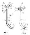
Die Vorrichtung
Im Bereich des distalen Endes
Die Form, insbesondere Biegung, des flexiblen Abschnitts
Hierbei bewirkt das in
Im Inneren des Einführungsteils
Durch den Führungskanal
An dem proximalen Ende
Im Inneren der Handhabe
Das Stellelement
In dem Stellelement
Um eine gleitende Lagerung des Stellelements
Da die Bowdenzüge
Zur manuellen Betätigung des Stellelements
Hierbei kann das Einführungsteil
Zur Übertragung der Steuerungsbewegung von der Betätigungseinrichtung
Somit wird eine Verstellbewegung des Gegenkupplungsstücks
Wie in
Durch die formschlüssige Verbindung zwischen Stellelement
Durch die kugelige oder sphärische Ausbildung der Berührungsfläche
Die primären Bowdenzüge
Bei dem Ausführungsbeispiel sind die Angriffspunkte
Durch die gleichen radialen Abstände werden die Stellbewegungen der sekundären Bowdenzüge
Das Gegenkupplungsstück
Die Berührfläche
In dem Gegenkupplungsstück
Die gemeinsame Durchführung
Der sekundäre Führungskanal
Das aus der Handhabe
Bei diesem Einführungsteil
Das Einführungsteil
Hierdurch umgreift das Stellelement
Das Einführungsteil
An der Handhabe
Bei der Vorrichtung
Claims (11)
Translated fromGermanPriority Applications (5)
| Application Number | Priority Date | Filing Date | Title |
|---|---|---|---|
| DE201010008922DE102010008922A1 (en) | 2010-02-23 | 2010-02-23 | Device for observing and / or manipulating objects arranged in a cavity accessible through a narrow opening |
| PCT/EP2010/007710WO2011103903A1 (en) | 2010-02-23 | 2010-12-16 | Device for monitoring and/or manipulating objects arranged in a cavity that can be accessed through a narrow opening |
| JP2012553190AJP5511991B2 (en) | 2010-02-23 | 2010-12-16 | Device for observing and / or treating an object placed in a hollow chamber that can be reached through a narrow opening |
| EP10798734.9AEP2539007B1 (en) | 2010-02-23 | 2010-12-16 | Device for monitoring and/or manipulating objects arranged in a cavity that can be accessed through a narrow opening |
| US13/579,963US8864716B2 (en) | 2010-02-23 | 2010-12-16 | Device for monitoring and/or manipulating objects arranged in a cavity that can be accessed through a narrow opening |
Applications Claiming Priority (1)
| Application Number | Priority Date | Filing Date | Title |
|---|---|---|---|
| DE201010008922DE102010008922A1 (en) | 2010-02-23 | 2010-02-23 | Device for observing and / or manipulating objects arranged in a cavity accessible through a narrow opening |
Publications (1)
| Publication Number | Publication Date |
|---|---|
| DE102010008922A1true DE102010008922A1 (en) | 2011-08-25 |
Family
ID=43662265
Family Applications (1)
| Application Number | Title | Priority Date | Filing Date |
|---|---|---|---|
| DE201010008922WithdrawnDE102010008922A1 (en) | 2010-02-23 | 2010-02-23 | Device for observing and / or manipulating objects arranged in a cavity accessible through a narrow opening |
Country Status (5)
| Country | Link |
|---|---|
| US (1) | US8864716B2 (en) |
| EP (1) | EP2539007B1 (en) |
| JP (1) | JP5511991B2 (en) |
| DE (1) | DE102010008922A1 (en) |
| WO (1) | WO2011103903A1 (en) |
Cited By (1)
| Publication number | Priority date | Publication date | Assignee | Title |
|---|---|---|---|---|
| CN114994904A (en)* | 2022-05-24 | 2022-09-02 | 青岛百年康健医疗科技有限公司 | Endoscope head bending structure for hard tube optical fiber |
Families Citing this family (3)
| Publication number | Priority date | Publication date | Assignee | Title |
|---|---|---|---|---|
| DE102010008922A1 (en)* | 2010-02-23 | 2011-08-25 | Schölly Fiberoptic GmbH, 79211 | Device for observing and / or manipulating objects arranged in a cavity accessible through a narrow opening |
| DE102014008187B4 (en)* | 2014-06-04 | 2017-04-06 | Schölly Fiberoptic GmbH | High pressure cleaning instrument and cleaning process |
| US10799675B2 (en)* | 2016-03-21 | 2020-10-13 | Edwards Lifesciences Corporation | Cam controlled multi-direction steerable handles |
Citations (3)
| Publication number | Priority date | Publication date | Assignee | Title |
|---|---|---|---|---|
| US4688554A (en)* | 1986-04-10 | 1987-08-25 | American Hospital Supply Corp. | Directing cannula for an optical diagnostic system |
| DE4340707A1 (en)* | 1993-11-30 | 1995-06-01 | Wolf Gmbh Richard | manipulator |
| WO2006040466A1 (en)* | 2004-10-11 | 2006-04-20 | Sas Geyser | Device for guiding and manipulating a surgical instrument |
Family Cites Families (13)
| Publication number | Priority date | Publication date | Assignee | Title |
|---|---|---|---|---|
| US5478318A (en)* | 1990-07-26 | 1995-12-26 | Yoon; Inbae | Multiluminal endoscopic portal |
| US5395342A (en)* | 1990-07-26 | 1995-03-07 | Yoon; Inbae | Endoscopic portal |
| JP3730674B2 (en)* | 1994-12-16 | 2006-01-05 | オリンパス株式会社 | How to insert an endoscope |
| US6858005B2 (en)* | 2000-04-03 | 2005-02-22 | Neo Guide Systems, Inc. | Tendon-driven endoscope and methods of insertion |
| US6569105B1 (en) | 2000-09-14 | 2003-05-27 | Syntheon, Llc | Rotatable and deflectable biopsy forceps |
| US7165568B2 (en)* | 2003-05-29 | 2007-01-23 | Axial Technologies Limited | Rotating valve assembly |
| US7582071B2 (en)* | 2005-03-28 | 2009-09-01 | Tyco Healthcare Group Lp | Introducer seal assembly |
| US7615067B2 (en)* | 2006-06-05 | 2009-11-10 | Cambridge Endoscopic Devices, Inc. | Surgical instrument |
| US7658305B2 (en) | 2006-10-25 | 2010-02-09 | Ethicon Endo-Surgery, Inc. | Adhesive applier with articulating tip |
| US20080249536A1 (en)* | 2007-02-15 | 2008-10-09 | Hansen Medical, Inc. | Interface assembly for controlling orientation of robotically controlled medical instrument |
| US7731072B2 (en) | 2007-06-18 | 2010-06-08 | Ethicon Endo-Surgery, Inc. | Surgical stapling and cutting instrument with improved anvil opening features |
| US8118783B2 (en)* | 2008-01-30 | 2012-02-21 | Tyco Healthcare Group Lp | Access assembly with spherical valve |
| DE102010008922A1 (en)* | 2010-02-23 | 2011-08-25 | Schölly Fiberoptic GmbH, 79211 | Device for observing and / or manipulating objects arranged in a cavity accessible through a narrow opening |
- 2010
- 2010-02-23DEDE201010008922patent/DE102010008922A1/ennot_activeWithdrawn
- 2010-12-16JPJP2012553190Apatent/JP5511991B2/enactiveActive
- 2010-12-16EPEP10798734.9Apatent/EP2539007B1/ennot_activeNot-in-force
- 2010-12-16USUS13/579,963patent/US8864716B2/ennot_activeExpired - Fee Related
- 2010-12-16WOPCT/EP2010/007710patent/WO2011103903A1/enactiveApplication Filing
Patent Citations (3)
| Publication number | Priority date | Publication date | Assignee | Title |
|---|---|---|---|---|
| US4688554A (en)* | 1986-04-10 | 1987-08-25 | American Hospital Supply Corp. | Directing cannula for an optical diagnostic system |
| DE4340707A1 (en)* | 1993-11-30 | 1995-06-01 | Wolf Gmbh Richard | manipulator |
| WO2006040466A1 (en)* | 2004-10-11 | 2006-04-20 | Sas Geyser | Device for guiding and manipulating a surgical instrument |
Cited By (1)
| Publication number | Priority date | Publication date | Assignee | Title |
|---|---|---|---|---|
| CN114994904A (en)* | 2022-05-24 | 2022-09-02 | 青岛百年康健医疗科技有限公司 | Endoscope head bending structure for hard tube optical fiber |
Also Published As
| Publication number | Publication date |
|---|---|
| EP2539007A1 (en) | 2013-01-02 |
| JP2013520212A (en) | 2013-06-06 |
| JP5511991B2 (en) | 2014-06-04 |
| US20120316494A1 (en) | 2012-12-13 |
| US8864716B2 (en) | 2014-10-21 |
| WO2011103903A1 (en) | 2011-09-01 |
| EP2539007B1 (en) | 2013-10-09 |
Similar Documents
| Publication | Publication Date | Title |
|---|---|---|
| EP2653120B1 (en) | Handle for a medical instrument | |
| EP3351191B1 (en) | Surgical instrument, in particular for neurosurgery | |
| EP2612609A2 (en) | Medical instrument | |
| DE102010008922A1 (en) | Device for observing and / or manipulating objects arranged in a cavity accessible through a narrow opening | |
| DE102011011244A1 (en) | Medical instrument | |
| DE4425705C2 (en) | Endoscopic instrument | |
| DE20110921U1 (en) | Uterine manipulator | |
| DE102004030030A1 (en) | Handle for a surgical instrument | |
| DE202011000828U1 (en) | Surgical instrument shaft and surgical instrument | |
| DE102012022573A1 (en) | Medical instrument | |
| WO2005079679A2 (en) | Medical cutting and/or holding instrument | |
| BE1030843B1 (en) | Crimp adapter, crimp assembly and connector | |
| DE102013222525B4 (en) | Valve device for at least one suction and/or rinsing channel of a surgical instrument | |
| EP2792319B1 (en) | Actuating element and rocker pair for an actuating element | |
| DE202010002642U1 (en) | Device for observing and / or manipulating objects arranged in a cavity accessible through a narrow opening | |
| DE102010033424A1 (en) | Endoscopic instrument e.g. laparoscopic surgical endoscopic instrument, for use as e.g. electrosurgical instrument, for minimum-invasive surgical endoscopic interventions in e.g. human, has pull rod engaging via yoke to pivotable jaw parts | |
| DE20311293U1 (en) | Surgical instrument with tubular shaft, contains flexible transmission comprising sections connected by ball joints | |
| DE10207207A1 (en) | Medical instrument | |
| DE102011056003A1 (en) | Surgical handle and surgical tubular shaft instrument with a surgical handle | |
| DE202007000427U1 (en) | Surgical handle and surgical instrument | |
| DE102009048600B4 (en) | Instrument for surgical purposes | |
| DE202007000425U1 (en) | Surgical instrument | |
| DE102019115004A1 (en) | Surgical instrument for minimally invasive surgery | |
| DE102011001891A1 (en) | Surgical instrument shaft for surgical instrument, has coupling unit for coupling with fastening unit of instrument and flush connection which stands in fluid connection with channel that is formed in instrument shaft | |
| DE10330030B4 (en) | Bipolar tubular shaft instrument |
Legal Events
| Date | Code | Title | Description |
|---|---|---|---|
| R016 | Response to examination communication | ||
| R120 | Application withdrawn or ip right abandoned | Effective date:20140127 |