DE102010004920A1 - Device for support of coupling trailer to trailer coupling of motor car e.g. passenger car, controls relative movement of trailer coupling of motor car based on determined relative position of trailer coupling of trailer - Google Patents
Device for support of coupling trailer to trailer coupling of motor car e.g. passenger car, controls relative movement of trailer coupling of motor car based on determined relative position of trailer coupling of trailerDownload PDFInfo
- Publication number
- DE102010004920A1 DE102010004920A1DE102010004920ADE102010004920ADE102010004920A1DE 102010004920 A1DE102010004920 A1DE 102010004920A1DE 102010004920 ADE102010004920 ADE 102010004920ADE 102010004920 ADE102010004920 ADE 102010004920ADE 102010004920 A1DE102010004920 A1DE 102010004920A1
- Authority
- DE
- Germany
- Prior art keywords
- trailer
- motor vehicle
- trailer hitch
- coupling
- relative position
- Prior art date
- Legal status (The legal status is an assumption and is not a legal conclusion. Google has not performed a legal analysis and makes no representation as to the accuracy of the status listed.)
- Ceased
Links
- 230000008878couplingEffects0.000titleclaimsabstractdescription38
- 238000010168coupling processMethods0.000titleclaimsabstractdescription38
- 238000005859coupling reactionMethods0.000titleclaimsabstractdescription38
- 230000033001locomotionEffects0.000titleclaimsabstractdescription20
- SAZUGELZHZOXHB-UHFFFAOYSA-NacecarbromalChemical compoundCCC(Br)(CC)C(=O)NC(=O)NC(C)=OSAZUGELZHZOXHB-UHFFFAOYSA-N0.000title1
- 238000000034methodMethods0.000claimsabstractdescription9
- 238000001514detection methodMethods0.000claimsdescription16
- 230000001953sensory effectEffects0.000claimsdescription6
- 230000003287optical effectEffects0.000description4
- 230000011664signalingEffects0.000description4
- 241001236644LaviniaSpecies0.000description3
- 230000000007visual effectEffects0.000description3
- 238000005259measurementMethods0.000description2
- BUHVIAUBTBOHAG-FOYDDCNASA-N(2r,3r,4s,5r)-2-[6-[[2-(3,5-dimethoxyphenyl)-2-(2-methylphenyl)ethyl]amino]purin-9-yl]-5-(hydroxymethyl)oxolane-3,4-diolChemical compoundCOC1=CC(OC)=CC(C(CNC=2C=3N=CN(C=3N=CN=2)[C@H]2[C@@H]([C@H](O)[C@@H](CO)O2)O)C=2C(=CC=CC=2)C)=C1BUHVIAUBTBOHAG-FOYDDCNASA-N0.000description1
- 230000004913activationEffects0.000description1
- 230000000295complement effectEffects0.000description1
- 230000005855radiationEffects0.000description1
- 230000035484reaction timeEffects0.000description1
- 238000009420retrofittingMethods0.000description1
- 238000002604ultrasonographyMethods0.000description1
Images


Classifications
- B—PERFORMING OPERATIONS; TRANSPORTING
- B62—LAND VEHICLES FOR TRAVELLING OTHERWISE THAN ON RAILS
- B62D—MOTOR VEHICLES; TRAILERS
- B62D15/00—Steering not otherwise provided for
- B62D15/02—Steering position indicators ; Steering position determination; Steering aids
- B62D15/027—Parking aids, e.g. instruction means
- B62D15/0285—Parking performed automatically
- B—PERFORMING OPERATIONS; TRANSPORTING
- B60—VEHICLES IN GENERAL
- B60D—VEHICLE CONNECTIONS
- B60D1/00—Traction couplings; Hitches; Draw-gear; Towing devices
- B60D1/14—Draw-gear or towing devices characterised by their type
- B60D1/167—Draw-gear or towing devices characterised by their type consisting of articulated or rigidly assembled bars or tubes forming a V-, Y-, or U-shaped draw gear
- B—PERFORMING OPERATIONS; TRANSPORTING
- B60—VEHICLES IN GENERAL
- B60D—VEHICLE CONNECTIONS
- B60D1/00—Traction couplings; Hitches; Draw-gear; Towing devices
- B60D1/24—Traction couplings; Hitches; Draw-gear; Towing devices characterised by arrangements for particular functions
- B60D1/36—Traction couplings; Hitches; Draw-gear; Towing devices characterised by arrangements for particular functions for facilitating connection, e.g. hitch catchers, visual guide means, signalling aids
- B—PERFORMING OPERATIONS; TRANSPORTING
- B60—VEHICLES IN GENERAL
- B60D—VEHICLE CONNECTIONS
- B60D1/00—Traction couplings; Hitches; Draw-gear; Towing devices
- B60D1/58—Auxiliary devices
Landscapes
- Engineering & Computer Science (AREA)
- Transportation (AREA)
- Mechanical Engineering (AREA)
- Chemical & Material Sciences (AREA)
- Combustion & Propulsion (AREA)
- Traffic Control Systems (AREA)
Abstract
Description
Translated fromGermanDie Erfindung betrifft eine Vorrichtung zur Unterstützung des Ankuppelns eines Anhängers an eine Anhängerkupplung eines Kraftfahrzeugs gemäß dem Oberbegriff des Anspruchs 1, sowie ein Verfahren zum Ankuppeln eines Anhängers an ein Kraftfahrzeug gemäß dem Oberbegriff des Anspruchs 7.The invention relates to a device for supporting the coupling of a trailer to a trailer hitch of a motor vehicle according to the preamble of claim 1, and a method for coupling a trailer to a motor vehicle according to the preamble of claim 7.
Stand der TechnikState of the art
Viele marktübliche Personenkraftwagen sind am Heck bereits mit einer Rückfahrkamera oder mit Ultraschallsensoren ausgestattet, um beim Rückwärtsfahren des Personenkraftwagens eine Annäherung an ein Hindernis zu erfassen. Neben derartigen Einparkhilfen gibt es auch bereits intelligente Einparkassistenten, die auf Knopfdruck vom Fahrer aktiviert werden können und dann auf der Grundlage der Relativposition des Personenkraftwagens zu vorhandenen Begrenzungen einer Parklücke, wie anderen parkenden Kraftfahrzeugen, Bäumen oder anderen Hindernissen, den Lenkeinschlag berechnen, der erforderlich ist, um den Personenkraftwagen in die ausgewählte Parklücke zu lenken. Personenkraftwagen mit Einparkassistent besitzen eine so genannte aktive Lenkung, die den Personenkraftwagen anschließend selbsttätig in die Parklücke lenkt, das heißt ohne Lenkbewegungen von Seiten des Fahrers, der nur noch leicht Gas geben und bremsen muss.Many commercially available cars are already equipped at the rear with a rear view camera or with ultrasonic sensors to detect an approach to an obstacle when reversing the passenger car. In addition to such parking aids, there are also intelligent parking assistants that can be activated by the driver at the push of a button and then calculate the steering angle that is required based on the relative position of the car to existing limitations of a parking space, such as other parked vehicles, trees or other obstacles to steer the passenger car into the selected parking space. Passenger cars with parking assistant have a so-called active steering, which then steers the car automatically into the parking space, that is, without steering movements from the side of the driver who only has to accelerate and brake.
Aus der
Ausgehend hiervon liegt der Erfindung die Aufgabe zugrunde, eine Vorrichtung und ein Verfahren der eingangs genannten Art dahingehend zu verbessern, dass an Kraftfahrzeugen bereits vorhandene Komponenten genutzt werden können, um das Ankuppeln eines Anhängers an die Anhängerkupplung des Kraftfahrzeugs zu unterstützen.Proceeding from this, the present invention seeks to improve a device and a method of the type mentioned in that on motor vehicles existing components can be used to support the coupling of a trailer to the trailer hitch of the motor vehicle.
Offenbarung der ErfindungDisclosure of the invention
Diese Aufgabe wird im Hinblick auf die Vorrichtung durch Einrichtungen zur Ermittlung der Relativposition einer Anhängerkupplung des Anhängers in Bezug zur Anhängerkupplung des Kraftfahrzeugs sowie zum Steuern der Bewegung des Kraftfahrzeugs und/oder einer Relativbewegung der Anhängerkupplung des Kraftfahrzeugs in Bezug zum Kraftfahrzeug auf der Grundlage der sensorisch ermittelten Relativposition gelöst.This object is achieved with respect to the device by means for determining the relative position of a trailer hitch of the trailer in relation to the trailer hitch of the motor vehicle and for controlling the movement of the motor vehicle and / or a relative movement of the trailer hitch of the motor vehicle with respect to the motor vehicle on the basis of sensory determined Relative position solved.
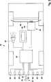
Eine bevorzugte Ausgestaltung der Erfindung sieht vor, dass die Einrichtungen zur Ermittlung der Relativposition eine Mehrzahl von Abstandsmessgeräten umfassen, die am Heck des Kraftfahrzeugs angeordnet und mit einem Steuergerät verbunden sind, das die Lenkung des Kraftfahrzeugs und/oder die Bewegung der Anhängerkupplung steuert. Die Relativposition der Anhängerkupplung des Anhängers in Bezug zur Anhängerkupplung des Kraftfahrzeugs kann in diesem Fall durch Triangulation aus den von mindestens zwei Abstandsmessgeräten gemessenen Abständen der Anhängerkupplung des Anhängers vom jeweiligen Abstandsmessgerät sowie dem gegenseitigen Abstand der Abstandsmessgeräte ermittelt werden.A preferred embodiment of the invention provides that the means for determining the relative position include a plurality of distance measuring devices which are arranged at the rear of the motor vehicle and connected to a control unit which controls the steering of the motor vehicle and / or the movement of the trailer coupling. The relative position of the trailer hitch with respect to the trailer hitch of the motor vehicle can in this case be determined by triangulation from the distances of the hitch of the trailer measured by at least two distance measuring devices from the respective distance measuring device and the mutual distance of the distance measuring devices.
Gemäß einer vorteilhaften Ausgestaltung der Erfindung handelt es sich bei den Abstandsmessgeräten um Ultraschallsensoren, die zweckmäßig in einem konstanten Abstand voneinander am Heck des Kraftfahrzeugs angeordnet sind, wobei sich die Erfassungsbereiche benachbarter Ultraschallsensoren stark überlappen, so dass bei Annäherung des Kraftfahrzeugs an den Anhänger dessen Anhängerkupplung in die Erfassungsbereiche von mindestens zwei Ultraschallsensoren eintaucht. Die Ultraschallsensoren sind vorzugsweise dieselben, wie diejenigen von Einparkhilfen oder Einparkassistenten, und können wie diese in einen hinteren Stoßfänger integriert sein. Die Ultraschallsensoren können die Funktion der Ultraschallsensoren der Einparkhilfe bzw. des Einparkassistenten mit übernehmen.According to an advantageous embodiment of the invention, the distance measuring devices are ultrasound sensors, which are expediently arranged at a constant distance from one another at the rear of the motor vehicle, wherein the detection ranges of adjacent ultrasonic sensors strongly overlap, so that when approaching the motor vehicle to the trailer whose trailer hitch in the detection ranges of at least two ultrasonic sensors is immersed. The ultrasonic sensors are preferably the same as those of parking aids or parking assistants, and like these may be integrated into a rear bumper. The ultrasonic sensors can take over the function of the ultrasonic sensors of the parking aid or the parking assistant.
Alternativ können die Einrichtungen zur Ermittlung der Relativposition mindestens eine Kamera und vorzugsweise zwei Kameras in Form von Videokameras umfassen.Alternatively, the means for determining the relative position may comprise at least one camera and preferably two cameras in the form of video cameras.
Bei dem erfindungsgemäßen Verfahren zum Ankuppeln eines Anhängers an ein Kraftfahrzeug wird eine Anhängerkupplung des Kraftfahrzeugs durch Lenken des Kraftfahrzeugs und/oder durch gesteuertes Bewegen der Anhängerkupplung in Bezug zum Kraftfahrzeug an eine Anhängerkupplung des Anhängers angenähert und dann mit der Anhängerkupplung des Anhängers gekuppelt, wobei nach einer sensorischen Erfassung der Anhängerkupplung des Anhängers eine Relativposition der Anhängerkupplung des Anhängers in Bezug zur Anhängerkupplung des Kraftfahrzeugs ermittelt und dann das Lenken des Kraftfahrzeugs und/oder das gesteuerte Bewegen der Anhängerkupplung in Bezug zum Kraftfahrzeug auf der Grundlage der ermittelten Relativposition vorgenommen wird.In the method according to the invention for coupling a trailer to a motor vehicle, a trailer coupling of the motor vehicle is approximated by steering the motor vehicle and / or by controlled movement of the trailer coupling with respect to the motor vehicle to a trailer hitch of the trailer and then coupled to the trailer hitch of the trailer, wherein after a sensory detection of the trailer hitch of the trailer determines a relative position of the trailer hitch of the trailer with respect to the trailer hitch of the motor vehicle and then the steering of the motor vehicle and / or the controlled movement of the hitch is made in relation to the motor vehicle on the basis of the determined relative position.
Auch das Kuppeln der beiden Anhängerkupplungen kann automatisch vorgenommen werden, indem zum Beispiel die Anhängerkupplung des Kraftfahrzeugs motorisch angehoben und mit der Anhängerkupplung des Anhängers in Eingriff gebracht wird. Alternativ oder zusätzlich können Anhängerkupplungen mit einem automatischen Verriegelungssystem verwendet werden, die sich beim Aufeinandertreffen selbsttätig verriegeln. Also, the coupling of the two trailer hitches can be made automatically, for example, by lifting the trailer hitch of the motor vehicle and engaged with the trailer hitch of the trailer. Alternatively or additionally, trailer hitches may be used with an automatic locking system that will automatically lock when it encounters each other.
Die sensorische Erfassung der Anhängerkupplung des Anhängers erfolgt vorteilhaft mit Hilfe von mindestens zwei Abstandsmessgeräten, so dass die Relativposition durch Triangulation aus den von den Abstandsmessgeräten gemessenen Abständen der Anhängerkupplung des Anhängers von dem jeweiligen Abstandsmessgerät und dem gegenseitigen Abstand der Abstandsmessgeräte ermittelt werden kann.The sensory detection of the trailer hitch of the trailer is advantageously carried out with the help of at least two distance measuring devices, so that the relative position can be determined by triangulation from the distances measured by the distance measuring devices of the trailer hitch of the trailer of the respective distance measuring device and the mutual distance of the distance measuring devices.
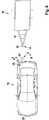
Dort, wo das Kraftfahrzeug mit einem aktiven Lenksystem ausgestattet ist, wird dieses vom Steuergerät gesteuert, um das Kraftfahrzeug entlang des zur gegenseitigen Annäherung der Anhängerkupplungen erforderlichen Bewegungspfades zu lenken. Dort, wo das Kraftfahrzeug mit einer gesteuert beweglichen Anhängerkupplung ausgestattet ist, wird das Kraftfahrzeug zweckmäßig geradeaus zurück gestoßen und die Anhängerkupplung vom Steuergerät um einen gemessenen seitlichen Versatz zwischen der Anhängerkupplung des Anhängers und einer vertikalen Längsmittelebene des Kraftfahrzeugs senkrecht zur Längsmittelebene in Bezug zum Kraftfahrzeug verschoben.Where the motor vehicle is equipped with an active steering system, this is controlled by the control unit to steer the motor vehicle along the movement path required for the mutual approach of the trailer hitches. Where the motor vehicle is equipped with a controlled movable trailer hitch, the motor vehicle is expediently pushed straight back and moved the trailer hitch from the control unit by a measured lateral offset between the trailer hitch of the trailer and a vertical longitudinal center plane of the motor vehicle perpendicular to the longitudinal center plane with respect to the motor vehicle.
Im Folgenden wird die Erfindung anhand von zwei in der Zeichnung dargestellten Ausführungsbeispielen näher erläutert. Es zeigenIn the following the invention will be explained in more detail with reference to two embodiments shown in the drawing. Show it
Die in der Zeichnung dargestellten Personenkraftwagen
Bei der Anhängerkupplung
Bei der Anhängerkupplung
Die Anhängerkupplung
Der Personenkraftwagen
Die Vorrichtung umfasst eine Mehrzahl von Ultraschallsensoren
Wie am besten in
Wie am besten in
Im Steuergerät
Darüber hinaus weist der Personenkraftwagen
Um das Ankuppeln des Anhängers
Zu diesem Zeitpunkt wird von der akustischen Signaleinrichtung
Durch Auswertung der Messwerte des in
Bei dem in den
Der Fahrer erhält nun von der akustischen Signaleinrichtung
Bei dem in
ZITATE ENTHALTEN IN DER BESCHREIBUNG QUOTES INCLUDE IN THE DESCRIPTION
Diese Liste der vom Anmelder aufgeführten Dokumente wurde automatisiert erzeugt und ist ausschließlich zur besseren Information des Lesers aufgenommen. Die Liste ist nicht Bestandteil der deutschen Patent- bzw. Gebrauchsmusteranmeldung. Das DPMA übernimmt keinerlei Haftung für etwaige Fehler oder Auslassungen.This list of the documents listed by the applicant has been generated automatically and is included solely for the better information of the reader. The list is not part of the German patent or utility model application. The DPMA assumes no liability for any errors or omissions.
Zitierte PatentliteraturCited patent literature
- DE 102007046677 A1[0003]DE 102007046677 A1[0003]
Claims (9)
Translated fromGermanPriority Applications (1)
| Application Number | Priority Date | Filing Date | Title |
|---|---|---|---|
| DE102010004920ADE102010004920A1 (en) | 2010-01-19 | 2010-01-19 | Device for support of coupling trailer to trailer coupling of motor car e.g. passenger car, controls relative movement of trailer coupling of motor car based on determined relative position of trailer coupling of trailer |
Applications Claiming Priority (1)
| Application Number | Priority Date | Filing Date | Title |
|---|---|---|---|
| DE102010004920ADE102010004920A1 (en) | 2010-01-19 | 2010-01-19 | Device for support of coupling trailer to trailer coupling of motor car e.g. passenger car, controls relative movement of trailer coupling of motor car based on determined relative position of trailer coupling of trailer |
Publications (1)
| Publication Number | Publication Date |
|---|---|
| DE102010004920A1true DE102010004920A1 (en) | 2011-07-21 |
Family
ID=44313935
Family Applications (1)
| Application Number | Title | Priority Date | Filing Date |
|---|---|---|---|
| DE102010004920ACeasedDE102010004920A1 (en) | 2010-01-19 | 2010-01-19 | Device for support of coupling trailer to trailer coupling of motor car e.g. passenger car, controls relative movement of trailer coupling of motor car based on determined relative position of trailer coupling of trailer |
Country Status (1)
| Country | Link |
|---|---|
| DE (1) | DE102010004920A1 (en) |
Cited By (46)
| Publication number | Priority date | Publication date | Assignee | Title |
|---|---|---|---|---|
| DE102012207649A1 (en) | 2012-05-08 | 2013-11-14 | Bayerische Motoren Werke Aktiengesellschaft | Driver assistance system for reverse movement of double-track motor vehicle along or relative to trailer, has operator viewable display device for displaying signal or recommendation for action of trailer |
| DE102012207648A1 (en) | 2012-05-08 | 2013-11-14 | Bayerische Motoren Werke Aktiengesellschaft | Driver assistance system for semi-automatic coupling of two-lane motor car with trailer, has sensor device, where system enables longitudinal guiding of motor car provided close to trailer by interventions in drive and brake system of car |
| DE102012207647A1 (en) | 2012-05-08 | 2013-11-14 | Bayerische Motoren Werke Aktiengesellschaft | Driver assistance system for reversing two-track vehicle with trailer, takes axis number, tiller length and track width into account for creating recommended course of action for driver based on trailer suspension geometry information |
| EP2682329A1 (en)* | 2012-07-05 | 2014-01-08 | Uusi, LLC | Vehicle trailer connect system |
| EP2821262A2 (en) | 2013-07-01 | 2015-01-07 | Haldex Brake Products GmbH | Electric/electronic-pneumatic-interface module |
| WO2015005795A3 (en)* | 2013-07-11 | 2015-04-02 | Smart Innovation As | System and method for connecting or disconnecting a trailer to a vehicle |
| US9233710B2 (en) | 2014-03-06 | 2016-01-12 | Ford Global Technologies, Llc | Trailer backup assist system using gesture commands and method |
| US9248858B2 (en) | 2011-04-19 | 2016-02-02 | Ford Global Technologies | Trailer backup assist system |
| DE102014113293A1 (en) | 2014-09-16 | 2016-03-17 | Valeo Schalter Und Sensoren Gmbh | Method for operating an ultrasonic sensor device of a motor vehicle, ultrasonic sensor device, driver assistance system and motor vehicle |
| US9290204B2 (en) | 2011-04-19 | 2016-03-22 | Ford Global Technologies, Llc | Hitch angle monitoring system and method |
| DE102014221077A1 (en) | 2014-10-16 | 2016-04-21 | Bayerische Motoren Werke Aktiengesellschaft | Location system on a motor vehicle with a trailer hitch |
| US9346396B2 (en) | 2011-04-19 | 2016-05-24 | Ford Global Technologies, Llc | Supplemental vehicle lighting system for vision based target detection |
| US9352777B2 (en) | 2013-10-31 | 2016-05-31 | Ford Global Technologies, Llc | Methods and systems for configuring of a trailer maneuvering system |
| US9374562B2 (en) | 2011-04-19 | 2016-06-21 | Ford Global Technologies, Llc | System and method for calculating a horizontal camera to target distance |
| DE102015107206A1 (en)* | 2014-05-07 | 2016-11-10 | GM Global Technology Operations LLC | Systems and methods for assisting in coupling a vehicle to a trailer |
| US9500497B2 (en) | 2011-04-19 | 2016-11-22 | Ford Global Technologies, Llc | System and method of inputting an intended backing path |
| US9506774B2 (en) | 2011-04-19 | 2016-11-29 | Ford Global Technologies, Llc | Method of inputting a path for a vehicle and trailer |
| US9511799B2 (en) | 2013-02-04 | 2016-12-06 | Ford Global Technologies, Llc | Object avoidance for a trailer backup assist system |
| US9522677B2 (en) | 2014-12-05 | 2016-12-20 | Ford Global Technologies, Llc | Mitigation of input device failure and mode management |
| US9533683B2 (en) | 2014-12-05 | 2017-01-03 | Ford Global Technologies, Llc | Sensor failure mitigation system and mode management |
| US9555832B2 (en) | 2011-04-19 | 2017-01-31 | Ford Global Technologies, Llc | Display system utilizing vehicle and trailer dynamics |
| US9566911B2 (en) | 2007-03-21 | 2017-02-14 | Ford Global Technologies, Llc | Vehicle trailer angle detection system and method |
| US9592851B2 (en) | 2013-02-04 | 2017-03-14 | Ford Global Technologies, Llc | Control modes for a trailer backup assist system |
| US9607242B2 (en) | 2015-01-16 | 2017-03-28 | Ford Global Technologies, Llc | Target monitoring system with lens cleaning device |
| US9610975B1 (en) | 2015-12-17 | 2017-04-04 | Ford Global Technologies, Llc | Hitch angle detection for trailer backup assist system |
| US9683848B2 (en) | 2011-04-19 | 2017-06-20 | Ford Global Technologies, Llc | System for determining hitch angle |
| US9723274B2 (en) | 2011-04-19 | 2017-08-01 | Ford Global Technologies, Llc | System and method for adjusting an image capture setting |
| US9836060B2 (en) | 2015-10-28 | 2017-12-05 | Ford Global Technologies, Llc | Trailer backup assist system with target management |
| US9854209B2 (en) | 2011-04-19 | 2017-12-26 | Ford Global Technologies, Llc | Display system utilizing vehicle and trailer dynamics |
| US9896130B2 (en) | 2015-09-11 | 2018-02-20 | Ford Global Technologies, Llc | Guidance system for a vehicle reversing a trailer along an intended backing path |
| US9926008B2 (en) | 2011-04-19 | 2018-03-27 | Ford Global Technologies, Llc | Trailer backup assist system with waypoint selection |
| US9969428B2 (en) | 2011-04-19 | 2018-05-15 | Ford Global Technologies, Llc | Trailer backup assist system with waypoint selection |
| US10112646B2 (en) | 2016-05-05 | 2018-10-30 | Ford Global Technologies, Llc | Turn recovery human machine interface for trailer backup assist |
| DE102017220459A1 (en) | 2017-11-16 | 2019-05-16 | Volkswagen Aktiengesellschaft | A method and trailer docking assistant for assisting a hitching operation of a motor vehicle approaching a trailer rearwardly |
| DE102018202613A1 (en) | 2018-02-21 | 2019-08-22 | Volkswagen Aktiengesellschaft | Method and system for supporting a coupling operation of a motor vehicle to a trailer |
| US10556473B2 (en) | 2013-07-11 | 2020-02-11 | Smart Patents As | System and method for connecting or disconnecting a trailer to a vehicle |
| DE102018215982A1 (en)* | 2018-09-19 | 2020-03-19 | Zf Friedrichshafen Ag | Device and method for controlling a vehicle for a swap body |
| WO2020052887A1 (en)* | 2018-09-10 | 2020-03-19 | Wabco Gmbh | Transverse steering method and transverse steering device for moving a vehicle into a target position, and vehicle for this purpose |
| WO2020052886A1 (en)* | 2018-09-10 | 2020-03-19 | Wabco Gmbh | Transverse steering method and transverse steering device for moving a vehicle into a target position, and vehicle for this purpose |
| US11179981B2 (en) | 2012-07-05 | 2021-11-23 | Uusi, Llc | Vehicle trailer connect system |
| US11208146B2 (en) | 2019-05-21 | 2021-12-28 | Ford Global Technologies, Llc | Acceptable zone for automated hitching with system performance considerations |
| EP3932701A1 (en) | 2020-07-02 | 2022-01-05 | Jungheinrich Aktiengesellschaft | Industrial truck with a jaw clutch, system comprising an industrial truck and a trailer and method for coupling a trailer to an industrial truck |
| EP4163133A1 (en) | 2021-10-08 | 2023-04-12 | Bayerische Motoren Werke Aktiengesellschaft | Method for supporting during a coupling process with a trailer, computing device and assistance system for a vehicle |
| EP4163134A1 (en) | 2021-10-08 | 2023-04-12 | Bayerische Motoren Werke Aktiengesellschaft | Method for supporting during a coupling process with a trailer, computing device and assistance system for a vehicle |
| DE102021213019A1 (en) | 2021-11-19 | 2023-05-25 | Zf Friedrichshafen Ag | Method and control device for controlling a vehicle |
| US11813909B2 (en) | 2020-05-29 | 2023-11-14 | Smart Patents As | Trailer coupling assembly and vehicle with trailer coupling assembly |
Citations (7)
| Publication number | Priority date | Publication date | Assignee | Title |
|---|---|---|---|---|
| DE4303815A1 (en)* | 1993-02-10 | 1994-08-11 | Bosch Gmbh Robert | Reversing and coupling auxiliary device for motor vehicles |
| DE10111529A1 (en)* | 2001-03-10 | 2002-09-12 | Deere & Co | Device for coupling a device to a work vehicle |
| DE10302545A1 (en)* | 2003-01-23 | 2004-07-29 | Conti Temic Microelectronic Gmbh | System for supporting motor vehicle coupling or docking using two-dimensional and three-dimensional image sensing has arrangement for detecting distance and angle between motor vehicle and coupling |
| DE102005052238A1 (en)* | 2005-11-02 | 2007-05-03 | GM Global Technology Operations, Inc., Detroit | Drive assistance system for monitoring the area behind the motor vehicle, has controller and sensor system whereby position of trailer draw bar ascertainable and control instruction are displayable for coupling with sensor system |
| DE102007046677A1 (en) | 2007-09-27 | 2009-04-09 | Claas Selbstfahrende Erntemaschinen Gmbh | Device and method for coupling a trailer to an agricultural towing vehicle |
| US20100013188A1 (en)* | 2008-07-16 | 2010-01-21 | Walt Joseph Ortmann | Trailer Connection Assist System |
| DE102009047836A1 (en)* | 2008-10-17 | 2010-06-02 | GM Global Technology Operations, Inc., Detroit | Fahrzeugandockunterstützungssystem |
- 2010
- 2010-01-19DEDE102010004920Apatent/DE102010004920A1/ennot_activeCeased
Patent Citations (7)
| Publication number | Priority date | Publication date | Assignee | Title |
|---|---|---|---|---|
| DE4303815A1 (en)* | 1993-02-10 | 1994-08-11 | Bosch Gmbh Robert | Reversing and coupling auxiliary device for motor vehicles |
| DE10111529A1 (en)* | 2001-03-10 | 2002-09-12 | Deere & Co | Device for coupling a device to a work vehicle |
| DE10302545A1 (en)* | 2003-01-23 | 2004-07-29 | Conti Temic Microelectronic Gmbh | System for supporting motor vehicle coupling or docking using two-dimensional and three-dimensional image sensing has arrangement for detecting distance and angle between motor vehicle and coupling |
| DE102005052238A1 (en)* | 2005-11-02 | 2007-05-03 | GM Global Technology Operations, Inc., Detroit | Drive assistance system for monitoring the area behind the motor vehicle, has controller and sensor system whereby position of trailer draw bar ascertainable and control instruction are displayable for coupling with sensor system |
| DE102007046677A1 (en) | 2007-09-27 | 2009-04-09 | Claas Selbstfahrende Erntemaschinen Gmbh | Device and method for coupling a trailer to an agricultural towing vehicle |
| US20100013188A1 (en)* | 2008-07-16 | 2010-01-21 | Walt Joseph Ortmann | Trailer Connection Assist System |
| DE102009047836A1 (en)* | 2008-10-17 | 2010-06-02 | GM Global Technology Operations, Inc., Detroit | Fahrzeugandockunterstützungssystem |
Cited By (75)
| Publication number | Priority date | Publication date | Assignee | Title |
|---|---|---|---|---|
| US9566911B2 (en) | 2007-03-21 | 2017-02-14 | Ford Global Technologies, Llc | Vehicle trailer angle detection system and method |
| US9971943B2 (en) | 2007-03-21 | 2018-05-15 | Ford Global Technologies, Llc | Vehicle trailer angle detection system and method |
| US9926008B2 (en) | 2011-04-19 | 2018-03-27 | Ford Global Technologies, Llc | Trailer backup assist system with waypoint selection |
| US9290204B2 (en) | 2011-04-19 | 2016-03-22 | Ford Global Technologies, Llc | Hitch angle monitoring system and method |
| US9854209B2 (en) | 2011-04-19 | 2017-12-26 | Ford Global Technologies, Llc | Display system utilizing vehicle and trailer dynamics |
| US9723274B2 (en) | 2011-04-19 | 2017-08-01 | Ford Global Technologies, Llc | System and method for adjusting an image capture setting |
| US9683848B2 (en) | 2011-04-19 | 2017-06-20 | Ford Global Technologies, Llc | System for determining hitch angle |
| US9969428B2 (en) | 2011-04-19 | 2018-05-15 | Ford Global Technologies, Llc | Trailer backup assist system with waypoint selection |
| US9248858B2 (en) | 2011-04-19 | 2016-02-02 | Ford Global Technologies | Trailer backup assist system |
| US9555832B2 (en) | 2011-04-19 | 2017-01-31 | Ford Global Technologies, Llc | Display system utilizing vehicle and trailer dynamics |
| US10609340B2 (en) | 2011-04-19 | 2020-03-31 | Ford Global Technologies, Llc | Display system utilizing vehicle and trailer dynamics |
| US9506774B2 (en) | 2011-04-19 | 2016-11-29 | Ford Global Technologies, Llc | Method of inputting a path for a vehicle and trailer |
| US9500497B2 (en) | 2011-04-19 | 2016-11-22 | Ford Global Technologies, Llc | System and method of inputting an intended backing path |
| US9374562B2 (en) | 2011-04-19 | 2016-06-21 | Ford Global Technologies, Llc | System and method for calculating a horizontal camera to target distance |
| US9346396B2 (en) | 2011-04-19 | 2016-05-24 | Ford Global Technologies, Llc | Supplemental vehicle lighting system for vision based target detection |
| DE102012207647A1 (en) | 2012-05-08 | 2013-11-14 | Bayerische Motoren Werke Aktiengesellschaft | Driver assistance system for reversing two-track vehicle with trailer, takes axis number, tiller length and track width into account for creating recommended course of action for driver based on trailer suspension geometry information |
| DE102012207648A1 (en) | 2012-05-08 | 2013-11-14 | Bayerische Motoren Werke Aktiengesellschaft | Driver assistance system for semi-automatic coupling of two-lane motor car with trailer, has sensor device, where system enables longitudinal guiding of motor car provided close to trailer by interventions in drive and brake system of car |
| DE102012207649A1 (en) | 2012-05-08 | 2013-11-14 | Bayerische Motoren Werke Aktiengesellschaft | Driver assistance system for reverse movement of double-track motor vehicle along or relative to trailer, has operator viewable display device for displaying signal or recommendation for action of trailer |
| DE102012207647B4 (en) | 2012-05-08 | 2023-03-09 | Bayerische Motoren Werke Aktiengesellschaft | Driver assistance system for reversing a two-lane motor vehicle with a trailer |
| US9914333B2 (en) | 2012-07-05 | 2018-03-13 | Uusi, Llc | Vehicle trailer connect system |
| EP2682329A1 (en)* | 2012-07-05 | 2014-01-08 | Uusi, LLC | Vehicle trailer connect system |
| US11179981B2 (en) | 2012-07-05 | 2021-11-23 | Uusi, Llc | Vehicle trailer connect system |
| US9592851B2 (en) | 2013-02-04 | 2017-03-14 | Ford Global Technologies, Llc | Control modes for a trailer backup assist system |
| US9511799B2 (en) | 2013-02-04 | 2016-12-06 | Ford Global Technologies, Llc | Object avoidance for a trailer backup assist system |
| EP2821262A2 (en) | 2013-07-01 | 2015-01-07 | Haldex Brake Products GmbH | Electric/electronic-pneumatic-interface module |
| DE102013106875A1 (en)* | 2013-07-01 | 2015-01-08 | Haldex Brake Products Gmbh | EPI module |
| DE102013106875B4 (en) | 2013-07-01 | 2019-01-31 | Haldex Brake Products Aktiebolag | EPI module |
| US10556473B2 (en) | 2013-07-11 | 2020-02-11 | Smart Patents As | System and method for connecting or disconnecting a trailer to a vehicle |
| WO2015005795A3 (en)* | 2013-07-11 | 2015-04-02 | Smart Innovation As | System and method for connecting or disconnecting a trailer to a vehicle |
| US9834049B2 (en) | 2013-07-11 | 2017-12-05 | Smart Patents As | System and method for connecting or disconnecting a trailer to a vehicle |
| CN105377592A (en)* | 2013-07-11 | 2016-03-02 | 斯马特创新公司 | System and method for connecting or disconnecting a trailer to a vehicle |
| US9352777B2 (en) | 2013-10-31 | 2016-05-31 | Ford Global Technologies, Llc | Methods and systems for configuring of a trailer maneuvering system |
| US9233710B2 (en) | 2014-03-06 | 2016-01-12 | Ford Global Technologies, Llc | Trailer backup assist system using gesture commands and method |
| DE102015107206A1 (en)* | 2014-05-07 | 2016-11-10 | GM Global Technology Operations LLC | Systems and methods for assisting in coupling a vehicle to a trailer |
| DE102014113293A1 (en) | 2014-09-16 | 2016-03-17 | Valeo Schalter Und Sensoren Gmbh | Method for operating an ultrasonic sensor device of a motor vehicle, ultrasonic sensor device, driver assistance system and motor vehicle |
| WO2016041737A1 (en) | 2014-09-16 | 2016-03-24 | Valeo Schalter Und Sensoren Gmbh | Method for operating an ultrasonic sensor device of a motor vehicle, ultrasonic sensor device, driver assistance system, and motor vehicle |
| DE102014221077A1 (en) | 2014-10-16 | 2016-04-21 | Bayerische Motoren Werke Aktiengesellschaft | Location system on a motor vehicle with a trailer hitch |
| US9522677B2 (en) | 2014-12-05 | 2016-12-20 | Ford Global Technologies, Llc | Mitigation of input device failure and mode management |
| US9533683B2 (en) | 2014-12-05 | 2017-01-03 | Ford Global Technologies, Llc | Sensor failure mitigation system and mode management |
| US9607242B2 (en) | 2015-01-16 | 2017-03-28 | Ford Global Technologies, Llc | Target monitoring system with lens cleaning device |
| US9896130B2 (en) | 2015-09-11 | 2018-02-20 | Ford Global Technologies, Llc | Guidance system for a vehicle reversing a trailer along an intended backing path |
| US10496101B2 (en) | 2015-10-28 | 2019-12-03 | Ford Global Technologies, Llc | Trailer backup assist system with multi-purpose camera in a side mirror assembly of a vehicle |
| US9836060B2 (en) | 2015-10-28 | 2017-12-05 | Ford Global Technologies, Llc | Trailer backup assist system with target management |
| US9610975B1 (en) | 2015-12-17 | 2017-04-04 | Ford Global Technologies, Llc | Hitch angle detection for trailer backup assist system |
| US10112646B2 (en) | 2016-05-05 | 2018-10-30 | Ford Global Technologies, Llc | Turn recovery human machine interface for trailer backup assist |
| WO2019096746A1 (en) | 2017-11-16 | 2019-05-23 | Volkswagen Aktiengesellschaft | Method and trailer-coupling assistance for assisting in the coupling process of a motor vehicle reversing towards a trailer |
| DE102017220459B4 (en) | 2017-11-16 | 2023-10-19 | Volkswagen Aktiengesellschaft | Method and trailer coupling assistant for supporting a coupling process of a motor vehicle reversing towards a trailer, and motor vehicle |
| DE102017220459A1 (en) | 2017-11-16 | 2019-05-16 | Volkswagen Aktiengesellschaft | A method and trailer docking assistant for assisting a hitching operation of a motor vehicle approaching a trailer rearwardly |
| US11186224B2 (en) | 2017-11-16 | 2021-11-30 | Volkswagen Aktiengesellschaft | Method and trailer-coupling assistance for assisting in the coupling process of a transportation vehicle reversing toward a trailer |
| CN110182197A (en)* | 2018-02-21 | 2019-08-30 | 大众汽车有限公司 | Method and system for auxiliary machine motor-car and the coupling process of trailer |
| US11427255B2 (en) | 2018-02-21 | 2022-08-30 | Volkswagen Aktiengesellschaft | Method and system for supporting a coupling operation of a transportation vehicle to a trailer |
| EP3530549A1 (en)* | 2018-02-21 | 2019-08-28 | Volkswagen Aktiengesellschaft | Method and system for supporting a coupling process of a motor vehicle to a trailer |
| DE102018202613A1 (en) | 2018-02-21 | 2019-08-22 | Volkswagen Aktiengesellschaft | Method and system for supporting a coupling operation of a motor vehicle to a trailer |
| DE102018202613B4 (en) | 2018-02-21 | 2025-01-02 | Volkswagen Aktiengesellschaft | Method and system for assisting a coupling process of a motor vehicle to a trailer |
| CN112839858A (en)* | 2018-09-10 | 2021-05-25 | 采埃孚商用车系统汉诺威有限公司 | Lateral steering method and lateral steering apparatus for moving vehicle to target location and vehicle thereof |
| US20210188355A1 (en)* | 2018-09-10 | 2021-06-24 | Zf Cv Systems Hannover Gmbh | Transverse steering method and transverse steering device for moving a vehicle into a target position, and vehicle for this purpose |
| CN112867661A (en)* | 2018-09-10 | 2021-05-28 | 采埃孚商用车系统汉诺威有限公司 | Lateral steering method and lateral steering apparatus for moving a vehicle into target positioning, and vehicle thereof |
| CN112867661B (en)* | 2018-09-10 | 2023-04-28 | 采埃孚商用车系统汉诺威有限公司 | Lateral steering method and lateral steering device for moving a vehicle into target positioning, and vehicle thereof |
| US11952038B2 (en) | 2018-09-10 | 2024-04-09 | Zf Cv Systems Europe Bv | Transverse steering method and transverse steering device for moving a vehicle into a target position, and vehicle for this purpose |
| WO2020052886A1 (en)* | 2018-09-10 | 2020-03-19 | Wabco Gmbh | Transverse steering method and transverse steering device for moving a vehicle into a target position, and vehicle for this purpose |
| CN112839858B (en)* | 2018-09-10 | 2023-02-14 | 采埃孚商用车系统汉诺威有限公司 | Lateral steering method and lateral steering device for moving a vehicle into target positioning and its vehicle |
| WO2020052887A1 (en)* | 2018-09-10 | 2020-03-19 | Wabco Gmbh | Transverse steering method and transverse steering device for moving a vehicle into a target position, and vehicle for this purpose |
| US11780501B2 (en)* | 2018-09-10 | 2023-10-10 | Zf Cv Systems Europe Bv | Transverse steering method and transverse steering device for moving a vehicle into a target position, and vehicle for this purpose |
| DE102018215982A1 (en)* | 2018-09-19 | 2020-03-19 | Zf Friedrichshafen Ag | Device and method for controlling a vehicle for a swap body |
| US11208146B2 (en) | 2019-05-21 | 2021-12-28 | Ford Global Technologies, Llc | Acceptable zone for automated hitching with system performance considerations |
| US11813909B2 (en) | 2020-05-29 | 2023-11-14 | Smart Patents As | Trailer coupling assembly and vehicle with trailer coupling assembly |
| DE102020117511A1 (en) | 2020-07-02 | 2022-01-05 | Jungheinrich Aktiengesellschaft | Industrial truck with a jaw coupling, system consisting of an industrial truck and a trailer and a method for coupling a trailer to an industrial truck |
| EP3932701A1 (en) | 2020-07-02 | 2022-01-05 | Jungheinrich Aktiengesellschaft | Industrial truck with a jaw clutch, system comprising an industrial truck and a trailer and method for coupling a trailer to an industrial truck |
| US12391079B2 (en) | 2020-07-02 | 2025-08-19 | Jungheinrich Ag | Industrial truck with a jaw coupling, a system including an industrial truck and a trailer, and a method for coupling a trailer to an industrial truck |
| WO2023057180A1 (en) | 2021-10-08 | 2023-04-13 | Bayerische Motoren Werke Aktiengesellschaft | Method for assisting during a coupling process with a trailer, computing device, and assistance system for a vehicle |
| WO2023057207A1 (en) | 2021-10-08 | 2023-04-13 | Bayerische Motoren Werke Aktiengesellschaft | Method for assisting during a coupling process with a trailer, computing device, and assistance system for a vehicle |
| EP4163134A1 (en) | 2021-10-08 | 2023-04-12 | Bayerische Motoren Werke Aktiengesellschaft | Method for supporting during a coupling process with a trailer, computing device and assistance system for a vehicle |
| EP4163133A1 (en) | 2021-10-08 | 2023-04-12 | Bayerische Motoren Werke Aktiengesellschaft | Method for supporting during a coupling process with a trailer, computing device and assistance system for a vehicle |
| US12434517B2 (en) | 2021-10-08 | 2025-10-07 | Bayerische Motoren Werke Aktiengesellschaft | Method for assisting during a coupling process with a trailer, computing device, and assistance system for a vehicle |
| DE102021213019A1 (en) | 2021-11-19 | 2023-05-25 | Zf Friedrichshafen Ag | Method and control device for controlling a vehicle |
Similar Documents
| Publication | Publication Date | Title |
|---|---|---|
| DE102010004920A1 (en) | Device for support of coupling trailer to trailer coupling of motor car e.g. passenger car, controls relative movement of trailer coupling of motor car based on determined relative position of trailer coupling of trailer | |
| EP1886905B1 (en) | Manoeuvring device for trailer with its own auxiliary drive | |
| DE102014107917A1 (en) | A method and apparatus for avoiding a collision of a vehicle comprising a motor vehicle and a trailer with an obstacle | |
| DE102016011324A1 (en) | A method of controlling a towing vehicle as it approaches and hitches to a trailer vehicle | |
| DE102008050685A1 (en) | Method for detecting threatening collision with obstacle during opening of door of parked vehicle i.e. passenger car, involves detecting position of obstacle using sensor devices during parking process of vehicle in parking lot | |
| DE102014000978A1 (en) | Method and device for controlling a team in a parking space | |
| EP1904342A1 (en) | Parking device | |
| DE102009046163A1 (en) | Method of assistance when parking out | |
| DE102008061357A1 (en) | Monitoring device and method for monitoring blind spot areas of a vehicle | |
| DE102012016866A1 (en) | Method for improved control of ultrasonic sensors, driver assistance device and motor vehicle | |
| DE102008047284A1 (en) | A driving assistance device for assisting a driver of a vehicle when parking out of a parking space | |
| DE102017108788A1 (en) | Vehicle reversing assistant | |
| DE102010041902A1 (en) | Method for carrying out a parking operation of a motor vehicle and device for controlling a parking operation of a motor vehicle | |
| DE102009045284A1 (en) | Method for supporting driver during driving of manoeuvre for coupling e.g. camping trailer, with coupling point at towing device of motor vehicle, involves representing distance and direction between point and towing device for driver | |
| EP2620326B2 (en) | Method and device for supporting a coupling procedure of a trailer | |
| DE102009039085A1 (en) | Method for maneuvering vehicle, involves detecting low-floor barricade in circumference of vehicle by remote sensor of vehicle, where distance of barricade to vehicle is determined | |
| DE102013205167A1 (en) | Noise suppression with dead-angle monitoring | |
| DE102010035299A1 (en) | Method for coupling e.g. caravan, with towing vehicle, involves actuating steering and driving function of trailer by individual wheel drives such that towing vehicle is manually or automatically coupled with trailer | |
| DE102012014207A1 (en) | Driver assistance device for carrying out park process for motor car, has shunting components terminated by stopping car, and control device outputs information about end of predetermined ranges of shunting components to driver of car | |
| DE102014115334A1 (en) | A method for assisting a driver of a motor vehicle when parking in a parking space, driver assistance system and motor vehicle | |
| DE102016117712A1 (en) | Method for at least semi-autonomous maneuvering of a motor vehicle taking into account a detection range of a sensor, driver assistance system and motor vehicle | |
| DE102010034142A1 (en) | A method of assisting a driver in driving a motor vehicle and driver assistance system | |
| DE102019204098A1 (en) | Method and driver assistance system for supporting a driver of a vehicle during a parking maneuver in a parallel parking space | |
| DE102006045418A1 (en) | Motor vehicle, has parking assistance system with sensors for distance measurement to obstacle, in particular for detecting moving direction of moving object, where presence of moving object is determined in detection range of sensors | |
| DE102014108949A1 (en) | A method for assisting a driver of a motor vehicle when parking, driver assistance system and motor vehicle |
Legal Events
| Date | Code | Title | Description |
|---|---|---|---|
| R016 | Response to examination communication | ||
| R002 | Refusal decision in examination/registration proceedings | ||
| R003 | Refusal decision now final | Effective date:20140408 |