DE102010004036A1 - Apparatus for generatively producing a three-dimensional object with continuous heat input - Google Patents
Apparatus for generatively producing a three-dimensional object with continuous heat inputDownload PDFInfo
- Publication number
- DE102010004036A1 DE102010004036A1DE102010004036ADE102010004036ADE102010004036A1DE 102010004036 A1DE102010004036 A1DE 102010004036A1DE 102010004036 ADE102010004036 ADE 102010004036ADE 102010004036 ADE102010004036 ADE 102010004036ADE 102010004036 A1DE102010004036 A1DE 102010004036A1
- Authority
- DE
- Germany
- Prior art keywords
- construction field
- heating
- powder material
- dimensional object
- frame
- Prior art date
- Legal status (The legal status is an assumption and is not a legal conclusion. Google has not performed a legal analysis and makes no representation as to the accuracy of the status listed.)
- Ceased
Links
- 238000010276constructionMethods0.000claimsabstractdescription65
- 239000000843powderSubstances0.000claimsabstractdescription44
- 238000010438heat treatmentMethods0.000claimsabstractdescription39
- 239000000463materialSubstances0.000claimsabstractdescription26
- 238000004519manufacturing processMethods0.000claimsabstractdescription8
- 239000004033plasticSubstances0.000claimsdescription2
- 229920003023plasticPolymers0.000claimsdescription2
- 238000005245sinteringMethods0.000claimsdescription2
- 229920000642polymerPolymers0.000description11
- 229920001577copolymerPolymers0.000description10
- 238000000149argon plasma sinteringMethods0.000description8
- 239000004952PolyamideSubstances0.000description6
- 238000000034methodMethods0.000description6
- 229920002647polyamidePolymers0.000description6
- 239000000203mixtureSubstances0.000description5
- 238000009826distributionMethods0.000description4
- -1polyarylethersulfansPolymers0.000description4
- 230000005855radiationEffects0.000description4
- OKTJSMMVPCPJKN-UHFFFAOYSA-NCarbonChemical compound[C]OKTJSMMVPCPJKN-UHFFFAOYSA-N0.000description3
- 239000004696Poly ether ether ketoneSubstances0.000description3
- 239000004793PolystyreneSubstances0.000description3
- VYPSYNLAJGMNEJ-UHFFFAOYSA-NSilicium dioxideChemical classO=[Si]=OVYPSYNLAJGMNEJ-UHFFFAOYSA-N0.000description3
- 239000000945fillerSubstances0.000description3
- 229910052751metalInorganic materials0.000description3
- 239000002184metalSubstances0.000description3
- 229920002530polyetherether ketonePolymers0.000description3
- 229920002223polystyrenePolymers0.000description3
- 238000007711solidificationMethods0.000description3
- 230000008023solidificationEffects0.000description3
- 229920002614Polyether block amidePolymers0.000description2
- GWEVSGVZZGPLCZ-UHFFFAOYSA-NTitan oxideChemical compoundO=[Ti]=OGWEVSGVZZGPLCZ-UHFFFAOYSA-N0.000description2
- 239000000654additiveSubstances0.000description2
- 239000002131composite materialSubstances0.000description2
- 238000011161developmentMethods0.000description2
- 230000018109developmental processEffects0.000description2
- 238000009434installationMethods0.000description2
- 229920001652poly(etherketoneketone)Polymers0.000description2
- 229920006260polyaryletherketonePolymers0.000description2
- 229920000728polyesterPolymers0.000description2
- 229920000098polyolefinPolymers0.000description2
- BUHVIAUBTBOHAG-FOYDDCNASA-N(2r,3r,4s,5r)-2-[6-[[2-(3,5-dimethoxyphenyl)-2-(2-methylphenyl)ethyl]amino]purin-9-yl]-5-(hydroxymethyl)oxolane-3,4-diolChemical compoundCOC1=CC(OC)=CC(C(CNC=2C=3N=CN(C=3N=CN=2)[C@H]2[C@@H]([C@H](O)[C@@H](CO)O2)O)C=2C(=CC=CC=2)C)=C1BUHVIAUBTBOHAG-FOYDDCNASA-N0.000description1
- 229910002016Aerosil® 200Inorganic materials0.000description1
- 229920000571Nylon 11Polymers0.000description1
- 229920000299Nylon 12Polymers0.000description1
- 229920002292Nylon 6Polymers0.000description1
- 229920000305Nylon 6,10Polymers0.000description1
- 229920002302Nylon 6,6Polymers0.000description1
- 229920000572Nylon 6/12Polymers0.000description1
- 229920006152PA1010Polymers0.000description1
- 229920006153PA4TPolymers0.000description1
- 229920008285Poly(ether ketone) PEKPolymers0.000description1
- 229920001283Polyalkylene terephthalatePolymers0.000description1
- 239000004698PolyethyleneSubstances0.000description1
- 239000004721Polyphenylene oxideSubstances0.000description1
- 239000004734Polyphenylene sulfideSubstances0.000description1
- 239000004743PolypropyleneSubstances0.000description1
- 229910000831SteelInorganic materials0.000description1
- 230000006978adaptationEffects0.000description1
- 239000000956alloySubstances0.000description1
- 229910045601alloyInorganic materials0.000description1
- 239000011324beadSubstances0.000description1
- 230000005540biological transmissionEffects0.000description1
- 229910052799carbonInorganic materials0.000description1
- 239000006229carbon blackSubstances0.000description1
- 239000004917carbon fiberSubstances0.000description1
- 239000002041carbon nanotubeSubstances0.000description1
- 229910021393carbon nanotubeInorganic materials0.000description1
- 239000000919ceramicSubstances0.000description1
- 230000001419dependent effectEffects0.000description1
- 229920001971elastomerPolymers0.000description1
- 239000000806elastomerSubstances0.000description1
- 238000010894electron beam technologyMethods0.000description1
- RTZKZFJDLAIYFH-UHFFFAOYSA-NetherSubstancesCCOCCRTZKZFJDLAIYFH-UHFFFAOYSA-N0.000description1
- 239000000835fiberSubstances0.000description1
- 239000003063flame retardantSubstances0.000description1
- 239000012530fluidSubstances0.000description1
- 239000013538functional additiveSubstances0.000description1
- 239000011521glassSubstances0.000description1
- 239000003365glass fiberSubstances0.000description1
- 229910002804graphiteInorganic materials0.000description1
- 239000010439graphiteSubstances0.000description1
- 239000012760heat stabilizerSubstances0.000description1
- 229930195733hydrocarbonNatural products0.000description1
- 150000002430hydrocarbonsChemical class0.000description1
- 238000009413insulationMethods0.000description1
- 150000002576ketonesChemical class0.000description1
- 150000002739metalsChemical class0.000description1
- 239000012764mineral fillerSubstances0.000description1
- 238000012986modificationMethods0.000description1
- 230000004048modificationEffects0.000description1
- 230000003647oxidationEffects0.000description1
- 238000007254oxidation reactionMethods0.000description1
- 239000000049pigmentSubstances0.000description1
- 229920001643poly(ether ketone)Polymers0.000description1
- 229920006139poly(hexamethylene adipamide-co-hexamethylene terephthalamide)Polymers0.000description1
- 229920000570polyetherPolymers0.000description1
- 229920000573polyethylenePolymers0.000description1
- 229920006380polyphenylene oxidePolymers0.000description1
- 229920000069polyphenylene sulfidePolymers0.000description1
- 229920001155polypropylenePolymers0.000description1
- 229920002981polyvinylidene fluoridePolymers0.000description1
- 230000001681protective effectEffects0.000description1
- 239000004576sandSubstances0.000description1
- 239000003381stabilizerSubstances0.000description1
- 239000010959steelSubstances0.000description1
- 238000005496temperingMethods0.000description1
- 239000004408titanium dioxideSubstances0.000description1
Images


Classifications
- B—PERFORMING OPERATIONS; TRANSPORTING
- B29—WORKING OF PLASTICS; WORKING OF SUBSTANCES IN A PLASTIC STATE IN GENERAL
- B29C—SHAPING OR JOINING OF PLASTICS; SHAPING OF MATERIAL IN A PLASTIC STATE, NOT OTHERWISE PROVIDED FOR; AFTER-TREATMENT OF THE SHAPED PRODUCTS, e.g. REPAIRING
- B29C35/00—Heating, cooling or curing, e.g. crosslinking or vulcanising; Apparatus therefor
- B29C35/007—Tempering units for temperature control of moulds or cores, e.g. comprising heat exchangers, controlled valves, temperature-controlled circuits for fluids
- B—PERFORMING OPERATIONS; TRANSPORTING
- B22—CASTING; POWDER METALLURGY
- B22F—WORKING METALLIC POWDER; MANUFACTURE OF ARTICLES FROM METALLIC POWDER; MAKING METALLIC POWDER; APPARATUS OR DEVICES SPECIALLY ADAPTED FOR METALLIC POWDER
- B22F10/00—Additive manufacturing of workpieces or articles from metallic powder
- B22F10/20—Direct sintering or melting
- B22F10/28—Powder bed fusion, e.g. selective laser melting [SLM] or electron beam melting [EBM]
- B—PERFORMING OPERATIONS; TRANSPORTING
- B22—CASTING; POWDER METALLURGY
- B22F—WORKING METALLIC POWDER; MANUFACTURE OF ARTICLES FROM METALLIC POWDER; MAKING METALLIC POWDER; APPARATUS OR DEVICES SPECIALLY ADAPTED FOR METALLIC POWDER
- B22F12/00—Apparatus or devices specially adapted for additive manufacturing; Auxiliary means for additive manufacturing; Combinations of additive manufacturing apparatus or devices with other processing apparatus or devices
- B22F12/10—Auxiliary heating means
- B22F12/13—Auxiliary heating means to preheat the material
- B—PERFORMING OPERATIONS; TRANSPORTING
- B22—CASTING; POWDER METALLURGY
- B22F—WORKING METALLIC POWDER; MANUFACTURE OF ARTICLES FROM METALLIC POWDER; MAKING METALLIC POWDER; APPARATUS OR DEVICES SPECIALLY ADAPTED FOR METALLIC POWDER
- B22F12/00—Apparatus or devices specially adapted for additive manufacturing; Auxiliary means for additive manufacturing; Combinations of additive manufacturing apparatus or devices with other processing apparatus or devices
- B22F12/10—Auxiliary heating means
- B22F12/17—Auxiliary heating means to heat the build chamber or platform
- B—PERFORMING OPERATIONS; TRANSPORTING
- B29—WORKING OF PLASTICS; WORKING OF SUBSTANCES IN A PLASTIC STATE IN GENERAL
- B29C—SHAPING OR JOINING OF PLASTICS; SHAPING OF MATERIAL IN A PLASTIC STATE, NOT OTHERWISE PROVIDED FOR; AFTER-TREATMENT OF THE SHAPED PRODUCTS, e.g. REPAIRING
- B29C64/00—Additive manufacturing, i.e. manufacturing of three-dimensional [3D] objects by additive deposition, additive agglomeration or additive layering, e.g. by 3D printing, stereolithography or selective laser sintering
- B29C64/10—Processes of additive manufacturing
- B29C64/141—Processes of additive manufacturing using only solid materials
- B29C64/153—Processes of additive manufacturing using only solid materials using layers of powder being selectively joined, e.g. by selective laser sintering or melting
- B—PERFORMING OPERATIONS; TRANSPORTING
- B33—ADDITIVE MANUFACTURING TECHNOLOGY
- B33Y—ADDITIVE MANUFACTURING, i.e. MANUFACTURING OF THREE-DIMENSIONAL [3-D] OBJECTS BY ADDITIVE DEPOSITION, ADDITIVE AGGLOMERATION OR ADDITIVE LAYERING, e.g. BY 3-D PRINTING, STEREOLITHOGRAPHY OR SELECTIVE LASER SINTERING
- B33Y30/00—Apparatus for additive manufacturing; Details thereof or accessories therefor
- B—PERFORMING OPERATIONS; TRANSPORTING
- B22—CASTING; POWDER METALLURGY
- B22F—WORKING METALLIC POWDER; MANUFACTURE OF ARTICLES FROM METALLIC POWDER; MAKING METALLIC POWDER; APPARATUS OR DEVICES SPECIALLY ADAPTED FOR METALLIC POWDER
- B22F12/00—Apparatus or devices specially adapted for additive manufacturing; Auxiliary means for additive manufacturing; Combinations of additive manufacturing apparatus or devices with other processing apparatus or devices
- B22F12/22—Driving means
- B22F12/222—Driving means for motion along a direction orthogonal to the plane of a layer
- B—PERFORMING OPERATIONS; TRANSPORTING
- B22—CASTING; POWDER METALLURGY
- B22F—WORKING METALLIC POWDER; MANUFACTURE OF ARTICLES FROM METALLIC POWDER; MAKING METALLIC POWDER; APPARATUS OR DEVICES SPECIALLY ADAPTED FOR METALLIC POWDER
- B22F12/00—Apparatus or devices specially adapted for additive manufacturing; Auxiliary means for additive manufacturing; Combinations of additive manufacturing apparatus or devices with other processing apparatus or devices
- B22F12/90—Means for process control, e.g. cameras or sensors
- B—PERFORMING OPERATIONS; TRANSPORTING
- B22—CASTING; POWDER METALLURGY
- B22F—WORKING METALLIC POWDER; MANUFACTURE OF ARTICLES FROM METALLIC POWDER; MAKING METALLIC POWDER; APPARATUS OR DEVICES SPECIALLY ADAPTED FOR METALLIC POWDER
- B22F2999/00—Aspects linked to processes or compositions used in powder metallurgy
- Y—GENERAL TAGGING OF NEW TECHNOLOGICAL DEVELOPMENTS; GENERAL TAGGING OF CROSS-SECTIONAL TECHNOLOGIES SPANNING OVER SEVERAL SECTIONS OF THE IPC; TECHNICAL SUBJECTS COVERED BY FORMER USPC CROSS-REFERENCE ART COLLECTIONS [XRACs] AND DIGESTS
- Y02—TECHNOLOGIES OR APPLICATIONS FOR MITIGATION OR ADAPTATION AGAINST CLIMATE CHANGE
- Y02P—CLIMATE CHANGE MITIGATION TECHNOLOGIES IN THE PRODUCTION OR PROCESSING OF GOODS
- Y02P10/00—Technologies related to metal processing
- Y02P10/25—Process efficiency
Landscapes
- Engineering & Computer Science (AREA)
- Chemical & Material Sciences (AREA)
- Materials Engineering (AREA)
- Manufacturing & Machinery (AREA)
- Physics & Mathematics (AREA)
- Mechanical Engineering (AREA)
- Optics & Photonics (AREA)
- Plasma & Fusion (AREA)
- Health & Medical Sciences (AREA)
- Oral & Maxillofacial Surgery (AREA)
- Thermal Sciences (AREA)
Abstract
Translated fromGermanDescription
Translated fromGermanDie vorliegende Erfindung bezieht sich auf eine Vorrichtung zum generativen Herstellen eines dreidimensionalen Objekts.The present invention relates to an apparatus for generatively producing a three-dimensional object.
Trotz der Verwendung der Heizeinrichtung kann es zu Temperaturinhomogenitäten innerhalb des Bauraums kommen, wodurch die mechanischen Eigenschaften der Objekte inhomogen sein können.Despite the use of the heating device, temperature inhomogeneities can occur within the construction space, as a result of which the mechanical properties of the objects can be inhomogeneous.
Es ist die Aufgabe der vorliegenden Erfindung, eine Vorrichtung zum generativen Herstellen eines dreidimensionalen Objekts vorzusehen, durch die die mechanischen Eigenschaften des hergestellten Objekts verbessert werden können.It is the object of the present invention to provide a device for the generative production of a three-dimensional object, by means of which the mechanical properties of the manufactured object can be improved.
Diese Aufgabe wird durch die Vorrichtung zum generativen Herstellen eines dreidimensionalen Objekts mit den Merkmalen des Anspruchs 1 gelöst. Vorteilhafte Weiterbildungen sind Gegenstand der Unteransprüche.This object is achieved by the apparatus for the generative production of a three-dimensional object with the features of
Bei einer vorteilhaften Weiterbildung wird beispielsweise der kontinuierliche Wärmeverlust durch die kontinuierliche Wärmezufuhr kompensiert, so dass Wärmeverluste am Rand des Baufelds minimiert werden können und eine bessere Temperaturverteilung bis zum Randbereich ermöglicht wird. Dadurch vergrößert sich das prozesssichere effektive Baufeld, und es können eine homogene Wärmezufuhr und Temperaturverteilung über das gesamte Baufeld erreicht werden.In an advantageous development, for example, the continuous heat loss is compensated by the continuous supply of heat, so that heat losses at the edge of the construction field can be minimized and a better temperature distribution is made possible up to the edge region. This increases the process-safe effective construction field, and it can be achieved a homogeneous heat and temperature distribution over the entire construction field.
Weitere Merkmale und Zweckmäßigkeiten der Erfindung ergeben sich aus der Beschreibung von Ausführungsbeispielen anhand der beigefügten Zeichnungen. Von den Figuren zeigen:Further features and advantages of the invention will become apparent from the description of embodiments with reference to the accompanying drawings. From the figures show:
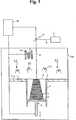
Die
Die Lasersintervorrichtung weist einen nach oben hin offenen Rahmen
Des Weiteren ist ein Beschichter
Der Beschichter
Mit dem Bezugszeichen
In der Vorrichtung ist eine Platte
Die Vorrichtung weist eine Heizvorrichtung
Ferner ist oberhalb des Rahmens
Die Beheizung einer aufgebrachten Pulverschicht erfolgt im dargestellten Ausführungsbeispiel über mindestens zwei, besser jedoch vier geradlinige Heizstrahler
Die Heizstrahler
Die Heizstrahler
Die Heizstrahler
Da die Heizvorrichtung
Bei dem Betrieb der Vorrichtung wird in einem ersten Schritt der Träger
Dieses neu aufgebrachte Pulver ist kaltes Pulver aus dem Vorratsbehälter
Anschließend steuert die Steuereinheit
In einem nächsten Schritt wird der Träger
In vorteilhafter Weise kompensiert eine kontinuierliche Wärmezufuhr der Heizvorrichtung
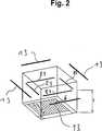
Die
Die
Die
Der weitere Aufbau und der Betrieb der Vorrichtung des zweiten bis vierten Ausführungsbeispiels sind gleich dem ersten Ausführungsbeispiel.The other structure and operation of the device of the second to fourth embodiments are the same as the first embodiment.
Die erfindungsgemäße Vorrichtung ist insbesondere bei Lasersinterprozessen anwendbar, bei denen die Temperatur der obersten Pulverschicht im Baufeld durch die weitere Heizvorrichtung auf wenige °C unterhalb der zur Verfestigung notwendigen Prozesstemperatur des Pulvermaterials vorerwärmt wird, wobei die zusätzliche Strahlung durch den Laserstrahl
Der Schutzumfang beschränkt sich nicht auf die dargestellten Ausführungsbeispiele, sondern er umfasst weitere Änderungen und Abwandlungen, sofern diese innerhalb des durch die beigefügten Ansprüche definierten Umfangs fallen.The scope of protection is not limited to the illustrated embodiments, but it includes other changes and modifications, provided that they fall within the scope defined by the appended claims.
Zum Beispiel ist die erfindungsgemäße Vorrichtung nicht nur beim Lasersintern anwendbar, sondern auf alle pulverbasierten, generativen Verfahren, bei denen pro aufzutragender Schicht ein Werkstoff bzw. ein Pulvermaterial verwendet wird, welches durch eine energiehaltige Strahlung verfestigt wird. Die energiehaltige Strahlung muss nicht unbedingt ein Laserstrahl
Die Heizvorrichtung muss nicht notwendigerweise durch Heizstrahler, Widerstandsheizungen und Heizmatten gebildet sein. Die Heizvorrichtung kann zum Beispiel auch durch eine Heizlampe oder durch Infrarotstrahler gebildet sein. Ferner ist es auch möglich, ein Temperierfluid durch Bereiche der Platte
Die Heizvorrichtungen
ZITATE ENTHALTEN IN DER BESCHREIBUNG QUOTES INCLUDE IN THE DESCRIPTION
Diese Liste der vom Anmelder aufgeführten Dokumente wurde automatisiert erzeugt und ist ausschließlich zur besseren Information des Lesers aufgenommen. Die Liste ist nicht Bestandteil der deutschen Patent- bzw. Gebrauchsmusteranmeldung. Das DPMA übernimmt keinerlei Haftung für etwaige Fehler oder Auslassungen.This list of the documents listed by the applicant has been generated automatically and is included solely for the better information of the reader. The list is not part of the German patent or utility model application. The DPMA assumes no liability for any errors or omissions.
Zitierte PatentliteraturCited patent literature
- EP 0764079 B1[0002, 0020]EP 0764079 B1[0002, 0020]
Claims (10)
Translated fromGermanPriority Applications (4)
| Application Number | Priority Date | Filing Date | Title |
|---|---|---|---|
| DE102010004036ADE102010004036A1 (en) | 2010-01-05 | 2010-01-05 | Apparatus for generatively producing a three-dimensional object with continuous heat input |
| US12/984,033US20110165340A1 (en) | 2010-01-05 | 2011-01-04 | Device for generatively manufacturing a three-dimensional object with continuous heat supply |
| EP11150079AEP2340925B1 (en) | 2010-01-05 | 2011-01-04 | Process for generative production of a three-dimensional object with continuous heat supply |
| JP2011000325AJP5784311B2 (en) | 2010-01-05 | 2011-01-05 | Generative manufacturing method of three-dimensional objects with continuous heat supply |
Applications Claiming Priority (1)
| Application Number | Priority Date | Filing Date | Title |
|---|---|---|---|
| DE102010004036ADE102010004036A1 (en) | 2010-01-05 | 2010-01-05 | Apparatus for generatively producing a three-dimensional object with continuous heat input |
Publications (1)
| Publication Number | Publication Date |
|---|---|
| DE102010004036A1true DE102010004036A1 (en) | 2011-07-07 |
Family
ID=43759421
Family Applications (1)
| Application Number | Title | Priority Date | Filing Date |
|---|---|---|---|
| DE102010004036ACeasedDE102010004036A1 (en) | 2010-01-05 | 2010-01-05 | Apparatus for generatively producing a three-dimensional object with continuous heat input |
Country Status (4)
| Country | Link |
|---|---|
| US (1) | US20110165340A1 (en) |
| EP (1) | EP2340925B1 (en) |
| JP (1) | JP5784311B2 (en) |
| DE (1) | DE102010004036A1 (en) |
Cited By (3)
| Publication number | Priority date | Publication date | Assignee | Title |
|---|---|---|---|---|
| DE102013005008A1 (en)* | 2013-03-22 | 2014-09-25 | Fraunhofer-Gesellschaft zur Förderung der angewandten Forschung e.V. | Process for the production of components from a material containing carbon nanotubes |
| DE102014204580A1 (en)* | 2014-03-12 | 2015-09-17 | Siemens Aktiengesellschaft | Device, method for the layered generation of components and process chamber |
| DE102015211170A1 (en)* | 2015-06-17 | 2016-12-22 | Eos Gmbh Electro Optical Systems | Device and method for producing a three-dimensional object |
Families Citing this family (52)
| Publication number | Priority date | Publication date | Assignee | Title |
|---|---|---|---|---|
| US12397363B2 (en)* | 2011-03-31 | 2025-08-26 | Norsk Titanium As | Method and arrangement for building metallic objects by solid freeform fabrication |
| DE102012200160A1 (en)* | 2012-01-06 | 2013-07-11 | Evonik Industries Ag | Device for the layered production of three-dimensional objects by means of a rotating application |
| DE102012200161A1 (en)* | 2012-01-06 | 2013-07-11 | Evonik Industries Ag | Device for the layered production of three-dimensional objects |
| DE102012212587A1 (en) | 2012-07-18 | 2014-01-23 | Eos Gmbh Electro Optical Systems | Apparatus and method for layering a three-dimensional object |
| US10471547B2 (en)* | 2012-12-21 | 2019-11-12 | European Space Agency | Additive manufacturing method using focused light heating source |
| EP2969485B1 (en) | 2013-03-15 | 2019-06-05 | 3D Systems, Inc. | Chute for laser sintering systems |
| DE102013109162A1 (en)* | 2013-08-23 | 2015-02-26 | Fit Fruth Innovative Technologien Gmbh | Device for producing three-dimensional objects |
| US9486878B2 (en) | 2014-06-20 | 2016-11-08 | Velo3D, Inc. | Apparatuses, systems and methods for three-dimensional printing |
| KR101635188B1 (en)* | 2014-07-11 | 2016-07-04 | (주)쓰리디스토리 | Unborn child sculpture printing service system and a method thereof |
| KR101665939B1 (en)* | 2014-07-18 | 2016-10-25 | 한국생산기술연구원 | A material supply apparatus for 3D manufacturing, a rapid 3D printer therewith, and 3D manufacturing method using it. |
| WO2016063198A1 (en) | 2014-10-20 | 2016-04-28 | Industrie Additive S.R.L. | Apparatus and method for additive manufacturing of three-dimensional objects |
| US10028841B2 (en) | 2015-01-27 | 2018-07-24 | K2M, Inc. | Interbody spacer |
| US20160213405A1 (en) | 2015-01-27 | 2016-07-28 | K2M, Inc. | Vertebral plate systems and methods of use |
| DE102015202964A1 (en)* | 2015-02-18 | 2016-08-18 | Eos Gmbh Electro Optical Systems | Device and method for producing a three-dimensional object |
| US10315408B2 (en)* | 2015-04-28 | 2019-06-11 | General Electric Company | Additive manufacturing apparatus and method |
| DE102015110264A1 (en)* | 2015-06-25 | 2016-12-29 | Cl Schutzrechtsverwaltungs Gmbh | Device for the generative production of at least one three-dimensional object |
| WO2017014964A1 (en)* | 2015-07-20 | 2017-01-26 | Applied Materials, Inc. | Additive manufacturing with multiple heat sources |
| US10065270B2 (en) | 2015-11-06 | 2018-09-04 | Velo3D, Inc. | Three-dimensional printing in real time |
| JP2017087562A (en)* | 2015-11-10 | 2017-05-25 | 株式会社リコー | 3D modeling equipment |
| EP3189960A4 (en)* | 2015-11-13 | 2018-04-04 | Technology Research Association for Future Additive Manufacturing | Three-dimensional additive manufacturing device, production method for three-dimensional additive manufacturing device, and production program for three-dimensional additive manufacturing device |
| US10286603B2 (en) | 2015-12-10 | 2019-05-14 | Velo3D, Inc. | Skillful three-dimensional printing |
| US11110517B2 (en)* | 2015-12-11 | 2021-09-07 | Eos Gmbh Electro Optical Systems | Method and device for examining an input data set of a generative layer building device |
| US20170239719A1 (en) | 2016-02-18 | 2017-08-24 | Velo3D, Inc. | Accurate three-dimensional printing |
| DE102016211313A1 (en)* | 2016-06-23 | 2017-12-28 | Eos Gmbh Electro Optical Systems | Automatic adjustment of a heating control in a generative layer construction device |
| EP3492244A1 (en) | 2016-06-29 | 2019-06-05 | VELO3D, Inc. | Three-dimensional printing system and method for three-dimensional printing |
| US11691343B2 (en) | 2016-06-29 | 2023-07-04 | Velo3D, Inc. | Three-dimensional printing and three-dimensional printers |
| US20180093418A1 (en) | 2016-09-30 | 2018-04-05 | Velo3D, Inc. | Three-dimensional objects and their formation |
| US20180126460A1 (en) | 2016-11-07 | 2018-05-10 | Velo3D, Inc. | Gas flow in three-dimensional printing |
| WO2018109735A2 (en)* | 2016-12-18 | 2018-06-21 | Csir | Preheating of material in an additive manufacturing apparatus |
| DE102016226322A1 (en)* | 2016-12-29 | 2018-07-05 | Eos Gmbh Electro Optical Systems | Method and device for generatively producing a three-dimensional object |
| US20180186082A1 (en) | 2017-01-05 | 2018-07-05 | Velo3D, Inc. | Optics in three-dimensional printing |
| US10315252B2 (en) | 2017-03-02 | 2019-06-11 | Velo3D, Inc. | Three-dimensional printing of three-dimensional objects |
| US11117194B2 (en) | 2017-03-15 | 2021-09-14 | Applied Materials, Inc. | Additive manufacturing having energy beam and lamp array |
| US10449696B2 (en) | 2017-03-28 | 2019-10-22 | Velo3D, Inc. | Material manipulation in three-dimensional printing |
| WO2018194481A1 (en)* | 2017-04-19 | 2018-10-25 | Siemens Aktiengesellschaft | Additive manufacturing technique including direct resistive heating of a workpiece |
| EP3415108B1 (en) | 2017-05-25 | 2024-09-04 | Stryker European Operations Holdings LLC | Fusion cage with integrated fixation and insertion features |
| US11006981B2 (en) | 2017-07-07 | 2021-05-18 | K2M, Inc. | Surgical implant and methods of additive manufacturing |
| KR101990306B1 (en)* | 2017-08-18 | 2019-06-18 | (주)센트롤 | Three-dimensional object |
| KR101990305B1 (en)* | 2017-08-18 | 2019-06-18 | (주)센트롤 | Three-dimensional object |
| JP6896866B2 (en)* | 2017-08-24 | 2021-06-30 | 三菱重工業株式会社 | Infrared heating device |
| WO2019051260A1 (en) | 2017-09-08 | 2019-03-14 | Pioneer Surgical Technology, Inc. | Intervertebral implants, instruments, and methods |
| WO2019103218A1 (en)* | 2017-11-24 | 2019-05-31 | 원광이엔텍 주식회사 | 3d printer |
| KR101855186B1 (en)* | 2017-11-24 | 2018-05-11 | 원광이엔텍 주식회사 | 3-dimensional printer having binder jet |
| KR101855185B1 (en)* | 2017-11-24 | 2018-05-11 | 원광이엔텍 주식회사 | 3-dimensional printer having heating device |
| US10272525B1 (en) | 2017-12-27 | 2019-04-30 | Velo3D, Inc. | Three-dimensional printing systems and methods of their use |
| US10144176B1 (en) | 2018-01-15 | 2018-12-04 | Velo3D, Inc. | Three-dimensional printing systems and methods of their use |
| JP2019155699A (en)* | 2018-03-12 | 2019-09-19 | 株式会社リコー | Stereo molding device and stereo molding method |
| JP2019155758A (en)* | 2018-03-14 | 2019-09-19 | 株式会社リコー | Stereo molding device, heat image measurement device, and heat image measurement method |
| GB2580040B (en)* | 2018-12-19 | 2022-01-19 | Stratasys Powder Production Ltd | Heater arrangements and apparatus for layer-by-layer formation of three-dimensional objects |
| CA3148849A1 (en) | 2019-07-26 | 2021-02-04 | Velo3D, Inc. | Quality assurance in formation of three-dimensional objects |
| US11534307B2 (en) | 2019-09-16 | 2022-12-27 | K2M, Inc. | 3D printed cervical standalone implant |
| NL2026035B1 (en)* | 2020-07-09 | 2022-03-15 | Additive Ind Bv | Method and apparatus for manufacturing an object by means of additive manufacturing |
Citations (2)
| Publication number | Priority date | Publication date | Assignee | Title |
|---|---|---|---|---|
| DE19516972C1 (en)* | 1995-05-09 | 1996-12-12 | Eos Electro Optical Syst | Device for producing a three-dimensional object by means of laser sintering |
| WO2008061730A1 (en)* | 2006-11-22 | 2008-05-29 | Eos Gmbh Electro Optical Systems | Device for building up a three-dimensional object layer by layer |
Family Cites Families (13)
| Publication number | Priority date | Publication date | Assignee | Title |
|---|---|---|---|---|
| DE4400523C2 (en)* | 1994-01-11 | 1996-07-11 | Eos Electro Optical Syst | Method and device for producing a three-dimensional object |
| US6656410B2 (en)* | 2001-06-22 | 2003-12-02 | 3D Systems, Inc. | Recoating system for using high viscosity build materials in solid freeform fabrication |
| US6930278B1 (en)* | 2004-08-13 | 2005-08-16 | 3D Systems, Inc. | Continuous calibration of a non-contact thermal sensor for laser sintering |
| US7569174B2 (en)* | 2004-12-07 | 2009-08-04 | 3D Systems, Inc. | Controlled densification of fusible powders in laser sintering |
| US7521652B2 (en)* | 2004-12-07 | 2009-04-21 | 3D Systems, Inc. | Controlled cooling methods and apparatus for laser sintering part-cake |
| US7357629B2 (en)* | 2005-03-23 | 2008-04-15 | 3D Systems, Inc. | Apparatus and method for aligning a removable build chamber within a process chamber |
| DE102005015870B3 (en)* | 2005-04-06 | 2006-10-26 | Eos Gmbh Electro Optical Systems | Device and method for producing a three-dimensional object |
| DE102005022308B4 (en)* | 2005-05-13 | 2007-03-22 | Eos Gmbh Electro Optical Systems | Apparatus and method for manufacturing a three-dimensional object with a heated powder coating material build-up material |
| DE102005024790A1 (en)* | 2005-05-26 | 2006-12-07 | Eos Gmbh Electro Optical Systems | Radiant heating for heating the building material in a laser sintering device |
| JP4856979B2 (en)* | 2006-02-24 | 2012-01-18 | 株式会社アスペクト | Powder sintering additive manufacturing apparatus and powder sintering additive manufacturing method |
| DE102006053121B3 (en)* | 2006-11-10 | 2007-12-27 | Eos Gmbh Electro Optical Systems | Coating device for applying powdered layers to a device for producing a three-dimensional object comprises longitudinal walls joined together, a unit for fluidizing powdered material and a controlling and/or regulating unit |
| DE102006055054A1 (en)* | 2006-11-22 | 2008-05-29 | Eos Gmbh Electro Optical Systems | Apparatus for layering a three-dimensional object |
| DE102006055056A1 (en)* | 2006-11-22 | 2008-05-29 | Eos Gmbh Electro Optical Systems | Coater for applying a layer of powdery building material in a device for producing a three-dimensional object in layers |
- 2010
- 2010-01-05DEDE102010004036Apatent/DE102010004036A1/ennot_activeCeased
- 2011
- 2011-01-04EPEP11150079Apatent/EP2340925B1/ennot_activeNot-in-force
- 2011-01-04USUS12/984,033patent/US20110165340A1/ennot_activeAbandoned
- 2011-01-05JPJP2011000325Apatent/JP5784311B2/ennot_activeExpired - Fee Related
Patent Citations (3)
| Publication number | Priority date | Publication date | Assignee | Title |
|---|---|---|---|---|
| DE19516972C1 (en)* | 1995-05-09 | 1996-12-12 | Eos Electro Optical Syst | Device for producing a three-dimensional object by means of laser sintering |
| EP0764079B1 (en) | 1995-05-09 | 1998-07-22 | EOS GmbH ELECTRO OPTICAL SYSTEMS | Device for producing a three-dimensional article by laser sintering |
| WO2008061730A1 (en)* | 2006-11-22 | 2008-05-29 | Eos Gmbh Electro Optical Systems | Device for building up a three-dimensional object layer by layer |
Cited By (3)
| Publication number | Priority date | Publication date | Assignee | Title |
|---|---|---|---|---|
| DE102013005008A1 (en)* | 2013-03-22 | 2014-09-25 | Fraunhofer-Gesellschaft zur Förderung der angewandten Forschung e.V. | Process for the production of components from a material containing carbon nanotubes |
| DE102014204580A1 (en)* | 2014-03-12 | 2015-09-17 | Siemens Aktiengesellschaft | Device, method for the layered generation of components and process chamber |
| DE102015211170A1 (en)* | 2015-06-17 | 2016-12-22 | Eos Gmbh Electro Optical Systems | Device and method for producing a three-dimensional object |
Also Published As
| Publication number | Publication date |
|---|---|
| EP2340925B1 (en) | 2013-04-03 |
| JP5784311B2 (en) | 2015-09-24 |
| US20110165340A1 (en) | 2011-07-07 |
| EP2340925A1 (en) | 2011-07-06 |
| JP2011140222A (en) | 2011-07-21 |
Similar Documents
| Publication | Publication Date | Title |
|---|---|---|
| EP2340925B1 (en) | Process for generative production of a three-dimensional object with continuous heat supply | |
| EP3099469B1 (en) | Method and device for the improved control of the energy input in a generative layer construction method | |
| EP1976680B1 (en) | Apparatus and method for the production of a three-dimensional object by means of a coating device for powdered structural material | |
| EP2361178B1 (en) | Device for the generative production of a three-dimensional object with an isolated construction field | |
| EP3059076B1 (en) | Method and device for generating a three-dimensional object | |
| EP3036086B1 (en) | Device for producing three-dimensional objects | |
| DE102012012344B4 (en) | Method and device for the production of workpieces by jet melting of pulverulent material | |
| EP1896247B1 (en) | Method and device for producing a 3d object by means of a generative 3d-method | |
| EP2386405B1 (en) | Device for generative manufacturing of a three dimensional object with restricted construction area | |
| EP2291281B1 (en) | Device for layer-wise producing a three-dimensional object | |
| EP3297811B1 (en) | Method and device for producing a three-dimensional object | |
| EP1771267B1 (en) | Device and method for applying layers of a powdery material to a surface | |
| WO2019015707A1 (en) | METHOD AND DEVICE FOR PRODUCING 3D SHAPES WITH SPECTRUM TRANSFORMERS | |
| DE102009015282B4 (en) | Method and device for generatively producing a three-dimensional object | |
| DE102011085154A1 (en) | Device for preventing deposits on optical components in laser sintering | |
| DE102013224693A1 (en) | Method for the accelerated production of objects by means of generative production | |
| DE102017207264A1 (en) | Homogenization of energy input | |
| DE102012216515A1 (en) | Process for the layered production of low-distortion three-dimensional objects by means of cooling elements | |
| WO2017153187A1 (en) | Generative layer construction method having improved detail resolution, and device for carrying out the same | |
| EP3579998A1 (en) | Increase in surface quality | |
| DE102015012844A1 (en) | Method and device for the generative production of a three-dimensional molded article from a shapeless material by means of laser beam melting, as well as chamber device for the method and the device | |
| WO2021069003A1 (en) | Method and apparatus for producing 3d shaped articles using high-performance radiation emitters | |
| EP3459656A1 (en) | Method and device for additive production of a component | |
| DE102013109160A1 (en) | Device for producing three-dimensional objects |
Legal Events
| Date | Code | Title | Description |
|---|---|---|---|
| R016 | Response to examination communication | ||
| R002 | Refusal decision in examination/registration proceedings | ||
| R003 | Refusal decision now final | Effective date:20140423 |