DE102010002957A1 - Microarray with immobilization particles - Google Patents
Microarray with immobilization particlesDownload PDFInfo
- Publication number
- DE102010002957A1 DE102010002957A1DE102010002957ADE102010002957ADE102010002957A1DE 102010002957 A1DE102010002957 A1DE 102010002957A1DE 102010002957 ADE102010002957 ADE 102010002957ADE 102010002957 ADE102010002957 ADE 102010002957ADE 102010002957 A1DE102010002957 A1DE 102010002957A1
- Authority
- DE
- Germany
- Prior art keywords
- carrier substrate
- immobilization
- particle
- microarray
- particles
- Prior art date
- Legal status (The legal status is an assumption and is not a legal conclusion. Google has not performed a legal analysis and makes no representation as to the accuracy of the status listed.)
- Withdrawn
Links
- 239000002245particleSubstances0.000titleclaimsabstractdescription109
- 238000002493microarrayMethods0.000titleclaimsabstractdescription46
- 239000000758substrateSubstances0.000claimsabstractdescription120
- 230000003100immobilizing effectEffects0.000claimsabstractdescription11
- 238000000034methodMethods0.000claimsdescription34
- 239000011521glassSubstances0.000claimsdescription13
- 229920001169thermoplasticPolymers0.000claimsdescription12
- 239000004416thermosoftening plasticSubstances0.000claimsdescription12
- 239000004033plasticSubstances0.000claimsdescription11
- 239000011248coating agentSubstances0.000claimsdescription6
- 238000000576coating methodMethods0.000claimsdescription6
- 239000002689soilSubstances0.000claimsdescription6
- 239000002243precursorSubstances0.000claimsdescription4
- 238000004519manufacturing processMethods0.000claimsdescription3
- 230000035945sensitivityEffects0.000abstractdescription3
- 239000012815thermoplastic materialSubstances0.000description7
- 230000008901benefitEffects0.000description6
- 229920000089Cyclic olefin copolymerPolymers0.000description5
- BLRPTPMANUNPDV-UHFFFAOYSA-NSilaneChemical compound[SiH4]BLRPTPMANUNPDV-UHFFFAOYSA-N0.000description5
- 230000009477glass transitionEffects0.000description5
- 229910000077silaneInorganic materials0.000description5
- 230000008569processEffects0.000description4
- 239000000523sampleSubstances0.000description4
- 150000003384small moleculesChemical class0.000description4
- 239000012876carrier materialSubstances0.000description3
- 230000005484gravityEffects0.000description3
- 238000006557surface reactionMethods0.000description3
- 239000004593EpoxySubstances0.000description2
- 239000000853adhesiveSubstances0.000description2
- 230000001070adhesive effectEffects0.000description2
- 239000011324beadSubstances0.000description2
- 150000001925cycloalkenesChemical class0.000description2
- 238000001514detection methodMethods0.000description2
- 238000002795fluorescence methodMethods0.000description2
- 125000002485formyl groupChemical class[H]C(*)=O0.000description2
- 229910052739hydrogenInorganic materials0.000description2
- 239000001257hydrogenSubstances0.000description2
- 230000002209hydrophobic effectEffects0.000description2
- 230000003993interactionEffects0.000description2
- 239000007788liquidSubstances0.000description2
- 238000011068loading methodMethods0.000description2
- 102000039446nucleic acidsHuman genes0.000description2
- 108020004707nucleic acidsProteins0.000description2
- 150000007523nucleic acidsChemical class0.000description2
- 239000004417polycarbonateSubstances0.000description2
- 229920000515polycarbonatePolymers0.000description2
- 230000009467reductionEffects0.000description2
- 238000005406washingMethods0.000description2
- BUHVIAUBTBOHAG-FOYDDCNASA-N(2r,3r,4s,5r)-2-[6-[[2-(3,5-dimethoxyphenyl)-2-(2-methylphenyl)ethyl]amino]purin-9-yl]-5-(hydroxymethyl)oxolane-3,4-diolChemical compoundCOC1=CC(OC)=CC(C(CNC=2C=3N=CN(C=3N=CN=2)[C@H]2[C@@H]([C@H](O)[C@@H](CO)O2)O)C=2C(=CC=CC=2)C)=C1BUHVIAUBTBOHAG-FOYDDCNASA-N0.000description1
- 238000000018DNA microarrayMethods0.000description1
- 239000000020NitrocelluloseSubstances0.000description1
- 238000010521absorption reactionMethods0.000description1
- 238000009825accumulationMethods0.000description1
- 238000004026adhesive bondingMethods0.000description1
- 125000000217alkyl groupChemical group0.000description1
- 238000004458analytical methodMethods0.000description1
- 230000015572biosynthetic processEffects0.000description1
- 230000008859changeEffects0.000description1
- 238000006243chemical reactionMethods0.000description1
- 239000000470constituentSubstances0.000description1
- 238000001035dryingMethods0.000description1
- 238000004049embossingMethods0.000description1
- 238000005530etchingMethods0.000description1
- 238000007306functionalization reactionMethods0.000description1
- 230000006872improvementEffects0.000description1
- 238000005304joiningMethods0.000description1
- 238000002032lab-on-a-chipMethods0.000description1
- 239000000463materialSubstances0.000description1
- 239000000203mixtureSubstances0.000description1
- 229920001220nitrocellulosPolymers0.000description1
- 150000001282organosilanesChemical class0.000description1
- 125000002924primary amino groupChemical group[H]N([H])*0.000description1
- 102000004196processed proteins & peptidesHuman genes0.000description1
- 108090000765processed proteins & peptidesProteins0.000description1
- 102000004169proteins and genesHuman genes0.000description1
- 108090000623proteins and genesProteins0.000description1
- 238000011002quantificationMethods0.000description1
- 239000002516radical scavengerSubstances0.000description1
- FZHAPNGMFPVSLP-UHFFFAOYSA-NsilanamineChemical compound[SiH3]NFZHAPNGMFPVSLP-UHFFFAOYSA-N0.000description1
- 238000001179sorption measurementMethods0.000description1
- 238000003786synthesis reactionMethods0.000description1
- 238000009736wettingMethods0.000description1
Images


Classifications
- B—PERFORMING OPERATIONS; TRANSPORTING
- B01—PHYSICAL OR CHEMICAL PROCESSES OR APPARATUS IN GENERAL
- B01J—CHEMICAL OR PHYSICAL PROCESSES, e.g. CATALYSIS OR COLLOID CHEMISTRY; THEIR RELEVANT APPARATUS
- B01J19/00—Chemical, physical or physico-chemical processes in general; Their relevant apparatus
- B01J19/0046—Sequential or parallel reactions, e.g. for the synthesis of polypeptides or polynucleotides; Apparatus and devices for combinatorial chemistry or for making molecular arrays
- B—PERFORMING OPERATIONS; TRANSPORTING
- B01—PHYSICAL OR CHEMICAL PROCESSES OR APPARATUS IN GENERAL
- B01J—CHEMICAL OR PHYSICAL PROCESSES, e.g. CATALYSIS OR COLLOID CHEMISTRY; THEIR RELEVANT APPARATUS
- B01J2219/00—Chemical, physical or physico-chemical processes in general; Their relevant apparatus
- B01J2219/00274—Sequential or parallel reactions; Apparatus and devices for combinatorial chemistry or for making arrays; Chemical library technology
- B01J2219/00277—Apparatus
- B01J2219/00351—Means for dispensing and evacuation of reagents
- B01J2219/00382—Stamping
- B—PERFORMING OPERATIONS; TRANSPORTING
- B01—PHYSICAL OR CHEMICAL PROCESSES OR APPARATUS IN GENERAL
- B01J—CHEMICAL OR PHYSICAL PROCESSES, e.g. CATALYSIS OR COLLOID CHEMISTRY; THEIR RELEVANT APPARATUS
- B01J2219/00—Chemical, physical or physico-chemical processes in general; Their relevant apparatus
- B01J2219/00274—Sequential or parallel reactions; Apparatus and devices for combinatorial chemistry or for making arrays; Chemical library technology
- B01J2219/00277—Apparatus
- B01J2219/00351—Means for dispensing and evacuation of reagents
- B01J2219/00387—Applications using probes
- B—PERFORMING OPERATIONS; TRANSPORTING
- B01—PHYSICAL OR CHEMICAL PROCESSES OR APPARATUS IN GENERAL
- B01J—CHEMICAL OR PHYSICAL PROCESSES, e.g. CATALYSIS OR COLLOID CHEMISTRY; THEIR RELEVANT APPARATUS
- B01J2219/00—Chemical, physical or physico-chemical processes in general; Their relevant apparatus
- B01J2219/00274—Sequential or parallel reactions; Apparatus and devices for combinatorial chemistry or for making arrays; Chemical library technology
- B01J2219/00277—Apparatus
- B01J2219/00457—Dispensing or evacuation of the solid phase support
- B01J2219/00459—Beads
- B01J2219/00466—Beads in a slurry
- B—PERFORMING OPERATIONS; TRANSPORTING
- B01—PHYSICAL OR CHEMICAL PROCESSES OR APPARATUS IN GENERAL
- B01J—CHEMICAL OR PHYSICAL PROCESSES, e.g. CATALYSIS OR COLLOID CHEMISTRY; THEIR RELEVANT APPARATUS
- B01J2219/00—Chemical, physical or physico-chemical processes in general; Their relevant apparatus
- B01J2219/00274—Sequential or parallel reactions; Apparatus and devices for combinatorial chemistry or for making arrays; Chemical library technology
- B01J2219/00277—Apparatus
- B01J2219/00457—Dispensing or evacuation of the solid phase support
- B01J2219/00459—Beads
- B01J2219/00468—Beads by manipulation of individual beads
- B—PERFORMING OPERATIONS; TRANSPORTING
- B01—PHYSICAL OR CHEMICAL PROCESSES OR APPARATUS IN GENERAL
- B01J—CHEMICAL OR PHYSICAL PROCESSES, e.g. CATALYSIS OR COLLOID CHEMISTRY; THEIR RELEVANT APPARATUS
- B01J2219/00—Chemical, physical or physico-chemical processes in general; Their relevant apparatus
- B01J2219/00274—Sequential or parallel reactions; Apparatus and devices for combinatorial chemistry or for making arrays; Chemical library technology
- B01J2219/00277—Apparatus
- B01J2219/00497—Features relating to the solid phase supports
- B01J2219/005—Beads
- B—PERFORMING OPERATIONS; TRANSPORTING
- B01—PHYSICAL OR CHEMICAL PROCESSES OR APPARATUS IN GENERAL
- B01J—CHEMICAL OR PHYSICAL PROCESSES, e.g. CATALYSIS OR COLLOID CHEMISTRY; THEIR RELEVANT APPARATUS
- B01J2219/00—Chemical, physical or physico-chemical processes in general; Their relevant apparatus
- B01J2219/00274—Sequential or parallel reactions; Apparatus and devices for combinatorial chemistry or for making arrays; Chemical library technology
- B01J2219/00277—Apparatus
- B01J2219/00497—Features relating to the solid phase supports
- B01J2219/00527—Sheets
- B01J2219/00533—Sheets essentially rectangular
- B—PERFORMING OPERATIONS; TRANSPORTING
- B01—PHYSICAL OR CHEMICAL PROCESSES OR APPARATUS IN GENERAL
- B01J—CHEMICAL OR PHYSICAL PROCESSES, e.g. CATALYSIS OR COLLOID CHEMISTRY; THEIR RELEVANT APPARATUS
- B01J2219/00—Chemical, physical or physico-chemical processes in general; Their relevant apparatus
- B01J2219/00274—Sequential or parallel reactions; Apparatus and devices for combinatorial chemistry or for making arrays; Chemical library technology
- B01J2219/00583—Features relative to the processes being carried out
- B01J2219/00585—Parallel processes
- B—PERFORMING OPERATIONS; TRANSPORTING
- B01—PHYSICAL OR CHEMICAL PROCESSES OR APPARATUS IN GENERAL
- B01J—CHEMICAL OR PHYSICAL PROCESSES, e.g. CATALYSIS OR COLLOID CHEMISTRY; THEIR RELEVANT APPARATUS
- B01J2219/00—Chemical, physical or physico-chemical processes in general; Their relevant apparatus
- B01J2219/00274—Sequential or parallel reactions; Apparatus and devices for combinatorial chemistry or for making arrays; Chemical library technology
- B01J2219/00583—Features relative to the processes being carried out
- B01J2219/00596—Solid-phase processes
- B—PERFORMING OPERATIONS; TRANSPORTING
- B01—PHYSICAL OR CHEMICAL PROCESSES OR APPARATUS IN GENERAL
- B01J—CHEMICAL OR PHYSICAL PROCESSES, e.g. CATALYSIS OR COLLOID CHEMISTRY; THEIR RELEVANT APPARATUS
- B01J2219/00—Chemical, physical or physico-chemical processes in general; Their relevant apparatus
- B01J2219/00274—Sequential or parallel reactions; Apparatus and devices for combinatorial chemistry or for making arrays; Chemical library technology
- B01J2219/00583—Features relative to the processes being carried out
- B01J2219/00603—Making arrays on substantially continuous surfaces
- B01J2219/00646—Making arrays on substantially continuous surfaces the compounds being bound to beads immobilised on the solid supports
- B01J2219/00648—Making arrays on substantially continuous surfaces the compounds being bound to beads immobilised on the solid supports by the use of solid beads
Landscapes
- Chemical & Material Sciences (AREA)
- Organic Chemistry (AREA)
- Chemical Kinetics & Catalysis (AREA)
- Apparatus Associated With Microorganisms And Enzymes (AREA)
Abstract
Translated fromGermanDescription
Translated fromGermanDie vorliegende Erfindung betrifft ein Mikroarray, eine Vorrichtung zur Herstellung eines derartigen Mikroarrays, ein Verfahren zur Herstellung eines derartigen Mikroarrays sowie dessen Verwendung.The present invention relates to a microarray, an apparatus for producing such a microarray, a method for producing such a microarray, and the use thereof.
Stand der TechnikState of the art
Mikroarrays sind bioanalytische Werkzeuge, um aus komplexen Gemischen einzelne Molekülgruppen durch spezifische Schlüssel-Schloss-Bindungen an genau definierten Punkten (Spots) auf einem Trägersubstrat zu identifizieren und zu quantifizieren. Zum Einsatz kommen Mikroarrays für die Identifikation und Quantifizierung von Nukleinsäuren, Proteinen, Zellen und kleinen Molekülen (Englisch: „small molecules”).Microarrays are bioanalytical tools for identifying and quantifying individual molecular groups from complex mixtures through specific key-lock bonds at precisely defined spots on a carrier substrate. Microarrays are used for the identification and quantification of nucleic acids, proteins, cells and small molecules (English: "small molecules").
Mikroarrays werden herkömmlicherweise hergestellt, indem in einer Flüssigkeit gelöste Fängermoleküle auf ein Trägersubstrat aufgebracht (gespottet) und anschließend, beispielsweise unter Eintrocknen der Flüssigkeit, immobilisiert werden. Die Fängermoleküle können dabei Stück für Stück auf dem Trägersubstrat aufgebaut (On-Chip-Synthese) oder fertig synthetisiert auf das Trägersubstrat aufgedruckt werden. Dabei verbinden sich die Fängermoleküle mit der Oberfläche des Trägersubstrats beziehungsweise werden an der Oberfläche des Trägersubstrats adsorbiert. Ein derartiger Aufbau wird unter anderem auch als Biochip bezeichnet.Microarrays are conventionally prepared by scavenger molecules which are dissolved in a liquid are applied to a carrier substrate (spotted) and then immobilized, for example, while drying the liquid. The catcher molecules can be built up piece by piece on the carrier substrate (on-chip synthesis) or printed onto the carrier substrate ready synthesized. In this case, the catcher molecules connect to the surface of the carrier substrate or are adsorbed on the surface of the carrier substrate. Such a structure is also known as a biochip.
Die zu untersuchende Probe wird anschließend auf die Fängermolekül-Spots gegeben, wobei die zu detektierenden Molekülgruppen an die Fängermolekül-Spots binden und die übrigen Probenbestandteile abgespült werden. Das Ergebnis kann anschließend durch Detektionsmethoden, wie Fluoreszenzverfahren, ausgelesen werden.The sample to be examined is then added to the catcher molecule spots, whereby the molecule groups to be detected bind to the catcher molecule spots and the other sample constituents are rinsed off. The result can then be read out by detection methods, such as fluorescence methods.
Herkömmlicherweise weisen Mikroarrays ein Trägersubstrat aus Glas oder einem Kunststoff auf und werden als Wegwerfartikel eingesetzt. Fängermoleküle können jedoch nicht direkt an eine unbehandelte Glas- oder Kunststoffoberfläche anbinden und würden in den folgenden Schritten weggespült werden. Daher weisen Glas- oder Kunststoffträgersubstrate herkömmlicherweise eine vollflächige Oberflächenfunktionalisierung zum Immobilisieren von Fängermolekülen auf.Conventionally, microarrays have a carrier substrate made of glass or a plastic and are used as disposable items. However, catcher molecules can not bond directly to an untreated glass or plastic surface and would be washed away in the following steps. Therefore, glass or plastic carrier substrates conventionally have full surface functionalization for immobilizing capture molecules.
Eine poröse Mikrofluidstruktur ist aus der
Offenbarung der ErfindungDisclosure of the invention
Gegenstand der vorliegenden Erfindung ist ein Mikroarray, welches ein Trägersubstrat und eine Vielzahl von Immobilisierungspartikeln zum Immobilisieren von, insbesondere biochemischen, Fängermolekülen umfasst, wobei die Immobilisierungspartikel jeweils einen ersten, mit dem Trägersubstrat verbundenen Teilabschnitt und einen zweiten, offen liegenden Teilabschnitt aufweisen.The present invention is a microarray, which comprises a carrier substrate and a plurality of immobilization particles for immobilizing, in particular biochemical, capture molecules, the immobilization particles each having a first, connected to the carrier substrate portion and a second, exposed portion.
Zum Beispiel können die Immobilisierungspartikel Fängermoleküle ionisch Binden, kovalent Binden oder Adsorbieren, beispielsweise durch Wasserstoffbrückenbindungen und/oder hydrophobe Wechselwirkungen.For example, the immobilizing particles may ionically bind, covalently bond, or adsorb capture molecules, for example, through hydrogen bonds and / or hydrophobic interactions.
Das erfindungsgemäße Mikroarray hat den Vorteil, dass auf eine aufwendige und kostenintensive Oberflächenfunktionalisierung des Trägersubstrats verzichtet werden kann.The microarray according to the invention has the advantage that it is possible to dispense with a complicated and expensive surface functionalization of the carrier substrate.
Darüber hinaus kann durch den Verzicht einer Oberflächenfunktionalisierung des Trägersubstrats erzielt werden, dass Fängermoleküle und Probenmoleküle nicht auf der Oberfläche des Trägersubstrats, sondern nur lokal auf den Immobilisierungspartikeln immobilisiert werden. Da die Fängermoleküle außerhalb der Immobilisierungspartikel nicht auf dem Trägersubstrat haften können und nur auf den Immobilisierungspartikeln immobilisiert werden, wird die Spotgröße im Wesentlichen durch die Größe und Befestigungsweise der Immobilisierungspartikel definiert. Dies hat den Vorteil, dass bei großzügigem Spotten und anschließendem Waschen des Mikroarrays auch Spotting-Gerät mit einer geringen Spottinggenauigkeit eingesetzt werden können. Zudem kann auf diese Weise das Hintergrundrauschen beim Auslesen des Mikroarrays durch Detektionsverfahren, wie Fluoreszenzverfahren, reduziert werden.In addition, it can be achieved by omitting a surface functionalization of the carrier substrate that catcher molecules and sample molecules are not immobilized on the surface of the carrier substrate, but only locally on the immobilization particles. Since the capture molecules outside the immobilization particles can not adhere to the carrier substrate and are immobilized only on the immobilization particles, the spot size is essentially defined by the size and mode of attachment of the immobilization particles. This has the advantage that with generous spotting and subsequent washing of the microarray also spotting device can be used with a low Spottinggenauigkeit. In addition, in this way the background noise when reading out the microarray can be reduced by detection methods, such as fluorescence methods.
Zudem wird durch die Immobilisierungspartikel die Spotoberfläche vergrößert und es können mehr Moleküle pro Fläche gebunden werden. Da beispielsweise das Fluoreszenzsignal beim Auslesen von Mikroarrays von der Spotoberfläche abhängt, kann auf diese Weise eine höhere Sensitivität beim Auslesen des Mikroarrays erreicht werden.In addition, the immobilization particles increase the surface area of the spot and it is possible to bind more molecules per area. For example, since the fluorescence signal depends on the Spotoberfläche when reading microarrays, a higher sensitivity in reading the microarray can be achieved in this way.
Im Rahmen einer bevorzugten Ausführungsform des erfindungsgemäßen Mikroarrays ist der erste Teilabschnitt in das Trägersubstrat eingebunden, insbesondere eingeprägt. Insbesondere kann der erste Teilabschnitt dabei formschlüssig mit dem Trägersubstrat verbunden beziehungsweise formschlüssig in das Trägersubstrat eingebunden sein.Within the scope of a preferred embodiment of the microarray according to the invention, the first subsection is integrated into the carrier substrate, in particular embossed. In particular, the first part section can be positively connected to the carrier substrate or positively integrated into the carrier substrate.
Im Rahmen einer weiteren, bevorzugten Ausführungsform des erfindungsgemäßen Mikroarrays ragt der zweite Teilabschnitt aus dem Trägersubstrat heraus. Durch das Herausragen beziehungsweise die Erhöhung der Immobilisierungspartikel sind auch die Spots bezüglich der Trägersubstratoberfläche erhaben. Dies hat den Vorteil, dass die Signalebene, in der beispielsweise die Fluoreszenz gemessen wird, von der Oberfläche des Trägersubstrats beabstandet ist, was zu einer Senkung des Hintergrundsignals, einer Verbesserung des Verhältnisses zwischen dem eigentlichen Signal und dem Hintergrundrauschen (Englisch: „signal to noise ratio”) und damit zu einer weiteren Steigerung der Sensitivität führtWithin the scope of a further, preferred embodiment of the microarray according to the invention, the second subsection projects out of the carrier substrate. By protruding or increasing the immobilization particles and the spots are raised with respect to the carrier substrate surface. This has the advantage that the signal level in which, for example, the fluorescence is spaced from the surface of the carrier substrate, which leads to a reduction of the background signal, an improvement of the ratio between the actual signal and the background noise (English: "signal to noise ratio") and thus to a further increase in sensitivity
Im Rahmen einer Ausgestaltung einer weiteren, bevorzugten Ausführungsform des erfindungsgemäßen Mikroarrays ist das Trägersubstrat aus einem Kunststoff, insbesondere einem thermoplastischen Kunststoff, ausgebildet, wobei die Immobilisierungspartikel jeweils einen Partikelkern aus Glas oder Kunststoff, beispielsweise einem thermoplastischen Kunststoff, aufweisen. Im Rahmen einer anderen Ausgestaltung dieser weiteren, bevorzugten Ausführungsform des erfindungsgemäßen Mikroarrays ist das Trägersubstrat aus Glas ausgebildet, wobei die Immobilisierungspartikel jeweils einen Partikelkern aus Kunststoff, beispielsweise einem thermoplastischen Kunststoff, aufweisen. Beispielsweise können das Trägersubstrat beziehungsweise die Partikelkerne der Immobilisierungspartikel dabei aus einem Polycarbonat (PC), einem Cyclo-Olefin-Polymer (COP) oder einem Cyclo-Olefin-Copolymer (COC) ausgebildet sein. Auf diese Weise kann vorteilhafterweise beim Verbinden der Immobilisierungspartikel mit dem Trägersubstrat auf einen Klebstoff verzichtet werden.Within the scope of an embodiment of a further, preferred embodiment of the microarray according to the invention, the carrier substrate is formed from a plastic, in particular a thermoplastic, wherein the immobilization particles each have a particle core of glass or plastic, for example a thermoplastic. Within the scope of another embodiment of this further, preferred embodiment of the microarray according to the invention, the carrier substrate is made of glass, the immobilization particles each having a particle core made of plastic, for example a thermoplastic. For example, the carrier substrate or the particle cores of the immobilization particles may be formed from a polycarbonate (PC), a cyclo-olefin polymer (COP) or a cyclo-olefin copolymer (COC). In this way, it is advantageously possible to dispense with an adhesive when bonding the immobilization particles to the carrier substrate.
Im Rahmen einer Ausgestaltung einer weiteren, bevorzugten Ausführungsform des erfindungsgemäßen Mikroarrays ist die Oberfläche der Partikelkerne zum Immobilisieren von Fängermolekülen funktionalisiert. Im Rahmen einer anderen Ausgestaltung dieser Ausführungsform des erfindungsgemäßen Mikroarrays weisen die Partikelkerne jeweils eine Immobilisierungsbeschichtung zum Immobilisieren von Fängermolekülen auf. Beispielsweise können die Immobilisierungspartikel Glaspartikel (Englisch: „glass beads”) sein, die durch Reaktion mit einem Organosilan, beispielsweise einem Amino(alkyl)silan, einem Epoxysilan oder einem Aldehydsilan, funktionalisiert sind oder die eine funktionalisierte Beschichtung, beispielsweise eine Aminosilan-, Epoxysilan-, Aldehydsilan- oder Nitrocellulose-Beschichtung, aufweisen. Diese können ionische, kovalente beziehungsweise nicht-kovalente Bindungen mit Nukleinsäuren, Peptiden, Zellen und/oder kleinen Molekülen (Englisch: „small molecules”) eingehen. Dabei wird unter einer nicht-kovalenten Bindung Adsorption, insbesondere eine Bindung durch Wasserstoffbrückenbindungen und/oder hydrophobe Wechselwirkungen, verstanden. Durch ein vor dem Funktionalisieren beziehungsweise Beschichten durchgeführtes Ätzverfahren kann die Oberfläche der Glaspartikel vergrößert werden.Within the scope of an embodiment of a further, preferred embodiment of the microarray according to the invention, the surface of the particle cores is functionalized to immobilize capture molecules. In another embodiment of this embodiment of the microarray according to the invention, the particle cores each have an immobilization coating for immobilizing capture molecules. For example, the immobilization particles may be glass beads functionalized by reaction with an organosilane, for example, an amino (alkyl) silane, an epoxy silane or an aldehyde silane, or a functionalized coating, for example, an aminosilane, epoxy silane , Aldehyde silane or nitrocellulose coating. These can form ionic, covalent or non-covalent bonds with nucleic acids, peptides, cells and / or small molecules (English: "small molecules"). Here, by a non-covalent bond adsorption, in particular a bond by hydrogen bonds and / or hydrophobic interactions understood. By means of an etching process carried out before the functionalization or coating, the surface of the glass particles can be increased.
Die Immobilisierungspartikel können kugelförmig, faserförmig oder schotterartig ausgebildet sein. Zum Beispiel können die Immobilisierungspartikel eine durchschnittliche Partikelgröße in einem Bereich von ≥ 20 μm bis ≤ 500 μm beziehungsweise von ≥ 100 μm bis ≤ 500 μm aufweisen.The Immobilisierungspartikel may be spherical, fibrous or ballast-like. For example, the immobilization particles may have an average particle size in a range of ≥ 20 μm to ≤ 500 μm, or from ≥ 100 μm to ≤ 500 μm.
Im Rahmen einer weiteren, bevorzugten Ausführungsform des erfindungsgemäßen Mikroarrays sind auf dem zweiten Teilabschnitt Fängermoleküle immobilisiert. Dabei können auf unterschiedlichen Immobilisierungspartikeln unterschiedliche Fängermoleküle immobilisiert sein.Within the scope of a further, preferred embodiment of the microarray according to the invention, capture molecules are immobilized on the second subsection. Different capture molecules can be immobilized on different immobilization particles.
Ein weiterer Gegenstand der vorliegenden Erfindung ist eine Vorrichtung zur Herstellung eines erfindungsgemäßen Mikroarrays, welche einen Trägersubstrathalter zum Halten eines Trägersubstrats und mindestens einen bewegbaren Stift, insbesondere mehrere bewegbare Stifte, zur Aufnahme mindestens eines Immobilisierungspartikels und zum Transport des Immobilisierungspartikels zu einem von dem Trägersubstrathalter gehaltenen Trägersubstrat umfasst.Another object of the present invention is an apparatus for producing a microarray according to the invention, which comprises a carrier substrate holder for holding a carrier substrate and at least one movable pin, in particular a plurality of movable pins, for receiving at least one Immobilisierungspartikels and for transporting the Immobilisierungspartikels to a held by the carrier substrate holder carrier substrate includes.
Der mindestens eine Stift kann dabei eine planare Aufnahmefläche zur Aufnahme eines oder mehrerer Immobilisierungspartikel aufweisen.The at least one pin can have a planar receiving surface for receiving one or more Immobilisierungspartikel.
Im Rahmen einer bevorzugten Ausführungsform der erfindungsgemäßen Vorrichtung weist der mindestens eine Stift eine Aufnahmefläche mit mindestens einer Vertiefung, insbesondere mehreren Vertiefungen, zur Immobilisierungspartikelaufnahme auf. Dabei kann die mindestens eine Vertiefung zur Aufnahme eines Immobilisierungspartikels oder zur Aufnahme von mehreren Immobilisierungspartikeln ausgebildet sein. Vorzugsweise ist die mindestens eine Vertiefung zur Aufnahme eines Immobilisierungspartikels ausgebildet. Dabei kann die Form und Größe der mindestens einen Vertiefung etwa der Form und Größe eines halben Immobilisierungspartikels entsprechen. Auf diese Weise kann gewährleistet werden, dass in jeder Vertiefung nur ein Immobilisierungspartikel aufgenommen, zu dem Trägersubstrat transportiert und mit diesem verbunden wird.Within the scope of a preferred embodiment of the device according to the invention, the at least one pin has a receiving surface with at least one depression, in particular a plurality of depressions, for the immobilization particle absorption. In this case, the at least one depression can be designed to receive an immobilization particle or to receive a plurality of immobilization particles. Preferably, the at least one recess is designed for receiving a Immobilisierungspartikels. The shape and size of the at least one depression may correspond approximately to the shape and size of a half immobilization particle. In this way it can be ensured that only one immobilization particle is received in each well, transported to the carrier substrate and connected to it.
Insbesondere kann der mindestens eine Stift eine Aufnahmefläche mit zwei oder mehr, zueinander beabstandeten Vertiefungen aufweisen. Auf diese Weise können durch einen Stift mehrere zueinander in einem definierten Abstand angeordnete Immobilisierungspartikel gleichzeitig aufgenommen, transportiert und mit dem Trägersubstrat verbunden werden.In particular, the at least one pin can have a receiving surface with two or more, mutually spaced recesses. In this way, a plurality of immobilization particles arranged at a defined distance from one another can be simultaneously picked up, transported and connected to the carrier substrate by a pin.
Im Rahmen einer weiteren, bevorzugten Ausführungsform der erfindungsgemäßen Vorrichtung sind der Stift, insbesondere die Aufnahmefläche des Stifts, und/oder der Trägersubstrathalter, beheizbar. Auf diese Weise können Immobilisierungspartikel und Trägersubstrat thermoplastisch verbunden werden, insofern zumindest eines der zu verbindenden Elemente auf einem thermoplastischen Kunststoff basiert. Vorzugsweise ist dabei der mindestens eine Stift beziehungsweise der Trägersubstrathalter auf eine Temperatur beheizbar, welche ausreichend über der Glasübergangstemperatur (Tg) des thermoplastischen Kunststoffs des Immobilisierungspartikels und/oder des Trägersubstrats liegt. Zum Beispiel kann der mindestens eine Stift auf eine Temperatur beheizbar sein, welche mindestens 20 K, beispielsweise 20 K bis 40 K, über der Glasübergangstemperatur (Tg) des thermoplastischen Kunststoffs des Immobilisierungspartikels und/oder des Trägersubstrats liegt. Beispielsweise liegt die Glasübergangstemperatur (Tg) im Fall eines Polycarbonats bei etwa 140°C und im Fall eines Cyclo-Olefin-Copolymers bei etwa 145°C.Within the scope of a further, preferred embodiment of the device according to the invention, the pin, in particular the receiving surface of the pin, and / or the carrier substrate holder, can be heated. In this way, Immobilisierungspartikel and carrier substrate can be connected thermoplastically Be as far as at least one of the elements to be connected based on a thermoplastic material. In this case, the at least one pin or the carrier substrate holder is preferably heatable to a temperature which is sufficiently above the glass transition temperature (Tg ) of the thermoplastic of the immobilization particle and / or of the carrier substrate. For example, the at least one pin can be heated to a temperature which is at least 20 K, for example 20 K to 40 K, above the glass transition temperature (Tg ) of the thermoplastic of the Immobilisierungspartikels and / or the carrier substrate. For example, in the case of a polycarbonate, the glass transition temperature (Tg ) is about 140 ° C and, in the case of a cyclo-olefin copolymer, about 145 ° C.
Vorzugsweise ist der Trägersubstrathalter oberhalb (bezüglich der Gravitation) des mindestens einen Stifts positioniert oder positionierbar. Dabei ist der mindestens eine Stift vorzugsweise auf und ab (bezüglich der Gravitation) bewegbar, wobei die obere Fläche (bezüglich der Gravitation) des mindestens einen Stifts die Aufnahmefläche ist.Preferably, the carrier substrate holder is positioned or positionable above (with respect to gravity) the at least one pin. In this case, the at least one pin is preferably movable up and down (with respect to gravity), wherein the upper surface (with respect to gravity) of the at least one pin is the receiving surface.
Im Rahmen einer weiteren, bevorzugten Ausführungsform der erfindungsgemäßen Vorrichtung umfasst die Vorrichtung weiterhin einen Immobilisierungspartikelnachfüllbereich zur Aufnahme einer Vielzahl von Immobilisierungspartikeln, welcher einen Boden mit einer Bodenoberfläche aufweist. Der mindestens eine Stift ist dabei vorzugsweise durch den Boden von einer ersten Position, in der die Aufnahmefläche des Stifts unterhalb der Bodenoberfläche, beispielsweise unterhalb der Bodenoberfläche und innerhalb des Bodens, positioniert ist, in eine zweite Position, in der die Aufnahmefläche des Stifts oberhalb der Bodenoberfläche, insbesondere oberhalb der Bodenoberfläche und benachbart zu einem von dem Trägersubstrathalter über dem Immobilisierungspartikelnachfüllbereich gehaltenen Trägersubstrat, positioniert ist, bewegbar. Auf diese Weise können in der ersten Position Immobilisierungspartikel aus dem Immobilisierungspartikelnachfüllbereich auf die Aufnahmefläche des Stifts fallen und in der zweiten Position in Kontakt mit dem Trägersubstrat gebracht werden. Vorzugsweise liegen die Vertiefungsfreien Bereiche der Aufnahmefläche des mindestens einen Stifts in der zweiten Position an dem Trägersubstrat an. Auf diese Weise kann der erste Teilabschnitt der Immobilisierungspartikel in das Trägersubstrat eingebunden, insbesondere eingeprägt, werden. Durch die Tiefe der Vertiefung/en des mindestens einen Stifts kann dabei die Einbindetiefe, insbesondere die Einprägtiefe, der Immobilisierungspartikel in dem Trägersubstrat beziehungsweise die Höhe, um die die Immobilisierungspartikel aus dem Trägersubstrat herausragen, eingestellt werden.Within the scope of a further, preferred embodiment of the apparatus according to the invention, the apparatus further comprises an immobilization particle replenishment area for receiving a plurality of immobilization particles, which has a bottom with a bottom surface. The at least one pin is preferably positioned through the floor from a first position in which the receiving surface of the pin is positioned below the floor surface, for example below the floor surface and within the floor, to a second position where the receiving surface of the pin is above the floor Bottom surface, in particular above the bottom surface and adjacent to a carrier substrate held by the carrier substrate holder above the Immobilisierungspartikelnachfüllbereich supported, movable. In this way, in the first position, immobilization particles from the Immobilisierungspartikelnachfüllbereich fall on the receiving surface of the pen and be brought in the second position in contact with the carrier substrate. Preferably, the recess-free areas of the receiving surface of the at least one pin are in the second position on the carrier substrate. In this way, the first subsection of the immobilization particles can be incorporated into the carrier substrate, in particular embossed. The embedment depth, in particular the embossing depth, of the immobilization particles in the carrier substrate or the height by which the immobilization particles protrude from the carrier substrate can be set by the depth of the depression (s) of the at least one pin.
Darüber hinaus kann die Vorrichtung ein Immobilisierungspartikelreservoir aufweisen. Über dieses Immobilisierungspartikelreservoir können dem Immobilisierungspartikelnachfüllbereich weitere Immobilisierungspartikel zugeführt werden. Gegebenenfalls können der auch der Immobilisierungspartikelnachfüllbereich und/oder das Immobilisierungspartikelreservoir beheizbar sein.In addition, the device may have an immobilization particle reservoir. About this Immobilisierungspartikelreservoir the Immobilisierungspartikelachfüllbereich more Immobilisierungspartikel be supplied. If appropriate, the immobilization particle replenishment area and / or the immobilization particle reservoir can also be heated.
Ein weiterer Gegenstand der vorliegenden Erfindung ist ein Verfahren zur Herstellung eines Mikroarrays, insbesondere eines erfindungsgemäßen Mikroarrays, mit einer erfindungsgemäßen Vorrichtung, welches die Verfahrensschritte:
- a) Aufnehmen mindestens eines Immobilisierungspartikels durch den mindestens einen beweglichen Stift,
- b) Transport des mindestens einen Immobilisierungspartikels zu einem von dem Trägersubstrathalter gehaltenen Trägersubstrat und
- c) Verbinden des mindestens einen Immobilisierungspartikels mit dem Trägersubstrat,
- a) receiving at least one Immobilisierungspartikels by the at least one movable pin,
- b) transport of the at least one immobilization particle to a carrier substrate held by the carrier substrate holder and
- c) connecting the at least one immobilization particle to the carrier substrate,
Durch den Einsatz der erfindungsgemäßen Vorrichtung in dem erfindungsgemäßen Verfahren können Immobilisierungspartikel präzise, beispielsweise in einer Mikroarraykammer, positioniert und somit einzelnen Spots definiert werden.By using the device according to the invention in the method according to the invention, immobilization particles can be positioned precisely, for example in a microarray chamber, and thus individual spots can be defined.
Die Verfahrensschritte a) bis c) können gleichzeitig durch eine Vielzahl von beweglichen Stiften durchgeführt werden. Es ist jedoch ebenso möglich die Verfahrensschritte a) bis c) – unter einer Positionsänderung des Trägersubstrathalters und damit des zu bestückenden Trägersubstrats – mehrfach mit einem oder mehreren beweglichen Stiften zu wiederholen.The method steps a) to c) can be performed simultaneously by a plurality of movable pins. However, it is also possible to repeat the method steps a) to c) repeatedly with one or more movable pins under a change in position of the carrier substrate holder and thus of the carrier substrate to be loaded.
Zum Beispiel kann das Verbinden des mindestens einen Immobilisierungspartikels mit dem Trägersubstrat in Verfahrensschritt c) derart erfolgen, dass der mindestens eine Immobilisierungspartikel einen ersten, mit dem Trägersubstrat, insbesondere formschlüssig, verbundenen, Teilabschnitt und einen zweiten offen liegenden, insbesondere aus dem Trägersubstrat herausragenden, Teilabschnitt aufweist.For example, the bonding of the at least one immobilization particle to the carrier substrate in method step c) can take place in such a way that the at least one immobilization particle has a first subsection connected to the carrier substrate, in particular a positive fit, and a second, partially exposed subsection projecting especially from the carrier substrate having.
Im Rahmen einer bevorzugten Ausführungsform des erfindungsgemäßen Verfahrens erfolgt das Verbinden des mindestens einen Immobilisierungspartikels mit dem Trägersubstrat in Verfahrensschritt c) derart, dass der mindestens eine Immobilisierungspartikel einen ersten, in das Trägersubstrat, beispielsweise formschlüssig, eingebundenen/eingeprägten, Teilabschnitt und einen zweiten, aus dem Trägersubstrat herausragenden Teilabschnitt aufweist.Within the scope of a preferred embodiment of the method according to the invention, the at least one immobilization particle is joined to the carrier substrate in method step c) in such a way that the at least one immobilization particle has a first subsection which is embedded in the carrier substrate, for example a form-fitting, integrated / embossed subsection and a second Carrier substrate protruding portion has.
Das Verbinden kann gegebenenfalls durch Kleben erfolgen. Beim Verbinden durch Kleben sollte jedoch die Kompatibilität des Klebers mit den Sondenmaterialien, den zu prozessierenden Analyseproben, etc. berücksichtigt werden. The bonding can optionally be done by gluing. When bonding by bonding, however, the compatibility of the adhesive with the probe materials, the analysis samples to be processed, etc. should be considered.
Um dies zu vermeiden erfolgt das Verbinden in Verfahrensschritt c) im Rahmen einer weiteren, bevorzugten Ausführungsform des erfindungsgemäßen Verfahrens durch Einprägen des mindestens einen Immobilisierungspartikels in das Trägersubstrat oder eine verformbare Vorstufe des Trägersubstrats. Durch das Einprägen kann um die Immobilisierungspartikel ein Wulst entstehen. Das Einprägen von Immobilisierungspartikeln hat den Vorteil, dass die Immobilisierungspartikel – unabhängig vom Partikeldurchmesser – um die gleiche Höhe aus dem Trägersubstrat herausragen. Dadurch kann zum Auslesen des Mikroarrays eine definierte Signalebene gewährleistet werden, was insbesondere bei fluoreszierenden Ausleseverfahren von entscheidender Bedeutung ist.In order to avoid this, bonding in method step c) takes place within the scope of a further, preferred embodiment of the method according to the invention by impressing the at least one immobilization particle into the carrier substrate or a deformable precursor of the carrier substrate. The imprinting can create a bead around the immobilization particles. The imprinting of Immobilisierungspartikeln has the advantage that the Immobilisierungspartikel - regardless of the particle diameter - protrude by the same height from the carrier substrate. As a result, a defined signal level can be ensured for reading out the microarray, which is of crucial importance, in particular in the case of fluorescent readout methods.
Im Rahmen einer weiteren, bevorzugten Ausführungsform des erfindungsgemäßen Verfahrens wird Kleben dadurch vermieden, dass das Verbinden in Verfahrensschritt c) durch thermoplastisches Verbinden des mindestens einen Immobilisierungspartikels mit dem Trägersubstrat erfolgt.Within the scope of a further, preferred embodiment of the method according to the invention, bonding is avoided in that the bonding in method step c) takes place by thermoplastic bonding of the at least one immobilization particle to the carrier substrate.
Zum Beispiel können Immobilisierungspartikel mit einem Partikelkern aus einem thermoplastischen Kunststoff und/oder ein Trägermaterial aus einem thermoplastischen Kunststoff eingesetzt werden. Dabei kann nur das Trägermaterial, nur der mindestens eine Immobilisierungspartikel oder sowohl das Trägermaterial als auch der mindestens eine Immobilisierungspartikel aus einem thermoplastischen Kunststoff thermoplastisch verformt werden. Zum Beispiel kann ein Immobilisierungspartikel mit einem Partikelkern aus Glas in ein Trägersubstrat aus Kunststoff eingeprägt werden. Oder es kann ein Immobilisierungspartikel mit einem Partikelkern aus einem thermoplastischen Kunststoff unter thermoplastischer Verformung des Partikelkerns mit einem Trägersubstrat aus Glas verbunden werden. Oder es kann ein Immobilisierungspartikel mit einem Partikelkern aus einem thermoplastischen Kunststoff mit einem Trägersubstrat aus einem thermoplastischen Kunststoff unter thermoplastischer Verformung des Partikelkerns und/oder des Trägersubstrats verbunden werden.For example, Immobilisierungspartikel be used with a particle core made of a thermoplastic material and / or a carrier material made of a thermoplastic material. In this case, only the carrier material, only the at least one immobilization particles or both the carrier material and the at least one immobilization particles made of a thermoplastic material can be thermoplastically deformed. For example, an immobilization particle with a particle core of glass can be embossed into a carrier substrate made of plastic. Or an immobilization particle with a particle core of a thermoplastic material with thermoplastic deformation of the particle core can be connected to a carrier substrate made of glass. Or it can be an immobilization particle with a particle core of a thermoplastic material with a carrier substrate made of a thermoplastic material with thermoplastic deformation of the particle core and / or the carrier substrate are connected.
Der mindestens eine Stift beziehungsweise der Trägersubstrathalter wird dabei vorzugsweise auf eine Temperatur geheizt, welche (ausreichend) über der Glasübergangstemperatur (Tg) des thermoplastischen Kunststoffs des Trägersubstrats und/oder des mindestens einen Immobilisierungspartikels liegt. Zum Beispiel kann der mindestens eine Stift beziehungsweise der Trägersubstrathalter auf eine Temperatur geheizt werden, welche mindestens 20 K, beispielsweise 20 K bis 40 K, über der Glasübergangstemperatur (Tg) des thermoplastischen Kunststoffs des Immobilisierungspartikels und/oder des Trägersubstrats liegt.The at least one pin or the carrier substrate holder is preferably heated to a temperature which is (sufficiently) above the glass transition temperature (Tg) of the thermoplastic of the carrier substrate and / or of the at least one immobilization particle. For example, the at least one pin or the carrier substrate holder can be heated to a temperature which is at least 20 K, for example 20 K to 40 K, above the glass transition temperature (Tg ) of the thermoplastic of the immobilization particle and / or the carrier substrate.
Im Rahmen einer weiteren, bevorzugten Ausführungsform des erfindungsgemäßen Verfahrens umfasst das Verfahren weiterhin, insbesondere nach dem letzten Verfahrensschritt c), den Verfahrensschritt: d) Aufbringen, insbesondere punktuelles Aufbringen (Spotten), von Fängermolekülen auf den Immobilisierungspartikeln. Da durch das erfindungsgemäße Verfahren nicht die komplette Oberfläche des Trägersubstrats oberflächenmodifiziert wird, werden Fängermoleküle im Wesentlichen nur an den Immobilisierungspartikeln immobilisiert. Dies kann zum einen vorteilhafterweise eine Reduktion des Hintergrundrauschens zur Folge haben.Within the scope of a further, preferred embodiment of the process according to the invention, the process further comprises, in particular after the last process step c), the process step: d) application, in particular selective application (spotting) of catcher molecules on the immobilization particles. Since the entire surface of the carrier substrate is not surface-modified by the method according to the invention, capture molecules are essentially immobilized only on the immobilization particles. On the one hand, this can advantageously result in a reduction of the background noise.
Zum anderen kann das Aufbringen von Fängermolekülen derart erfolgen, dass eine Menge von Fängermolekülen beziehungsweise eine Menge einer Lösung von Fängermolekülen aufgebracht wird, welche größer ist als zum Benetzen der, insbesondere offen liegenden, Immobilisierungspartikeloberfläche notwendig. Gegebenenfalls können neben den Immobilisierungspartikeln auf der Trägersubstratoberfläche befindliche Fängermoleküle durch einen, insbesondere auf den Verfahrensschritt d) folgenden, Verfahrensschritt: e) Waschen des Trägersubstrats, insbesondere der Trägersubstratoberfläche, beziehungsweise des Mikroarrays, insbesondere der Immobilisierungspartikel aufweisenden Mikroarrayoberfläche, von der Trägersubstratoberfläche entfernt werden. Dies hat den Vorteil, dass Spotting-Geräte mit einer geringen Spottinggenauigkeit eingesetzt werden können und dennoch Spots mit einer, insbesondere durch die Größe und Befestigungsweise der Immobilisierungspartikel, definierten Spotgröße erzielt werden können.On the other hand, the application of catcher molecules can take place in such a way that a quantity of catcher molecules or a quantity of a solution of catcher molecules is applied which is greater than necessary for wetting the, in particular exposed, immobilization particle surface. If appropriate, capture molecules located on the carrier substrate surface next to the immobilization particles can be removed from the carrier substrate surface by a process step: e) washing the carrier substrate, in particular the carrier substrate surface or the microarray, in particular the microarray surface having the immobilization particles. This has the advantage that spotting devices can be used with a low Spottinggenauigkeit and yet spots can be achieved with a, in particular by the size and method of attachment of Immobilisierungspartikeln defined spot size.
Darüber hinaus betrifft die vorliegende Erfindung Mikroarrays, welche durch ein erfindungsgemäßes Verfahren hergestellt sind.Moreover, the present invention relates to microarrays which are produced by a method according to the invention.
Ein weiterer Gegenstand der vorliegenden Erfindung ist ein mikrofluidisches System, insbesondere ein Chiplabor (Englisch: „Lab-on-a-chip device”), beispielsweise für medizinische Anwendungen, zum Beispiel molekulare Diagnostik, welches ein erfindungsgemäßes Mikroarray umfasst.A further subject of the present invention is a microfluidic system, in particular a chip lab (English: "Lab-on-a-chip device"), for example for medical applications, for example molecular diagnostics, which comprises a microarray according to the invention.
Zeichnungendrawings
Weitere Vorteile und vorteilhafte Ausgestaltungen der erfindungsgemäßen Gegenstände werden durch die Zeichnungen veranschaulicht und in der nachfolgenden Beschreibung erläutert. Dabei ist zu beachten, dass die Zeichnungen nur beschreibenden Charakter haben und nicht dazu gedacht sind, die Erfindung in irgendeiner Form einzuschränken. Es zeigenFurther advantages and advantageous embodiments of the subject invention are illustrated by the drawings and explained in the following description. It is Note that the drawings are only descriptive and are not intended to limit the invention in any way. Show it
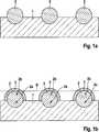
Das Trägersubstrat
Die
Die
Die
ZITATE ENTHALTEN IN DER BESCHREIBUNG QUOTES INCLUDE IN THE DESCRIPTION
Diese Liste der vom Anmelder aufgeführten Dokumente wurde automatisiert erzeugt und ist ausschließlich zur besseren Information des Lesers aufgenommen. Die Liste ist nicht Bestandteil der deutschen Patent- bzw. Gebrauchsmusteranmeldung. Das DPMA übernimmt keinerlei Haftung für etwaige Fehler oder Auslassungen.This list of the documents listed by the applicant has been generated automatically and is included solely for the better information of the reader. The list is not part of the German patent or utility model application. The DPMA assumes no liability for any errors or omissions.
Zitierte PatentliteraturCited patent literature
- DE 102007036906 A1[0006]DE 102007036906 A1[0006]
Claims (15)
Translated fromGermanPriority Applications (5)
| Application Number | Priority Date | Filing Date | Title |
|---|---|---|---|
| DE102010002957ADE102010002957A1 (en) | 2010-03-17 | 2010-03-17 | Microarray with immobilization particles |
| US13/635,148US20130102500A1 (en) | 2010-03-17 | 2011-01-20 | Microarray Comprising Immobilisation Particles |
| EP11700665AEP2547437A1 (en) | 2010-03-17 | 2011-01-20 | Microarray comprising immobilisation particles |
| PCT/EP2011/050763WO2011113628A1 (en) | 2010-03-17 | 2011-01-20 | Microarray comprising immobilisation particles |
| CN201180014007.3ACN102791370B (en) | 2010-03-17 | 2011-01-20 | Microarrays with Immobilized Particles |
Applications Claiming Priority (1)
| Application Number | Priority Date | Filing Date | Title |
|---|---|---|---|
| DE102010002957ADE102010002957A1 (en) | 2010-03-17 | 2010-03-17 | Microarray with immobilization particles |
Publications (1)
| Publication Number | Publication Date |
|---|---|
| DE102010002957A1true DE102010002957A1 (en) | 2011-09-22 |
Family
ID=43877235
Family Applications (1)
| Application Number | Title | Priority Date | Filing Date |
|---|---|---|---|
| DE102010002957AWithdrawnDE102010002957A1 (en) | 2010-03-17 | 2010-03-17 | Microarray with immobilization particles |
Country Status (5)
| Country | Link |
|---|---|
| US (1) | US20130102500A1 (en) |
| EP (1) | EP2547437A1 (en) |
| CN (1) | CN102791370B (en) |
| DE (1) | DE102010002957A1 (en) |
| WO (1) | WO2011113628A1 (en) |
Families Citing this family (3)
| Publication number | Priority date | Publication date | Assignee | Title |
|---|---|---|---|---|
| CN104535780B (en)* | 2014-11-05 | 2016-09-14 | 黄辉 | A microfluidic chip, sensor and particle immobilization method for immobilizing particles |
| US11130985B2 (en)* | 2014-11-27 | 2021-09-28 | Hitachi High-Tech Corporation | Spot array substrate, method for producing same, and nucleic acid polymer analysis method and device |
| JP7339245B2 (en)* | 2017-06-12 | 2023-09-05 | エッセンリックス コーポレーション | Homogeneous assay method |
Citations (1)
| Publication number | Priority date | Publication date | Assignee | Title |
|---|---|---|---|---|
| DE102007036906A1 (en) | 2007-05-07 | 2008-11-13 | Stiftung Caesar Center Of Advanced European Studies And Research | Test strip production method for execution of e.g. blood analysis, involves structuring laminar expanded and thin layer by application of hydrophobic substance, where separate segments form free regions from substance |
Family Cites Families (16)
| Publication number | Priority date | Publication date | Assignee | Title |
|---|---|---|---|---|
| US6000603A (en)* | 1997-05-23 | 1999-12-14 | 3M Innovative Properties Company | Patterned array of metal balls and methods of making |
| EP1028349A1 (en)* | 1997-10-27 | 2000-08-16 | Sekisui Chemical Co., Ltd. | Apparatus for spraying microparticles and spraying method using the apparatus, and method for manufacturing liquid crystal display |
| ATE341003T1 (en)* | 1999-02-16 | 2006-10-15 | Applera Corp | DEVICE FOR HANDLING BEADS |
| US20030044320A1 (en)* | 2001-08-31 | 2003-03-06 | Shun Luo | High throughput screening micro array platform |
| US6916620B2 (en)* | 2002-03-15 | 2005-07-12 | Eastman Kodak Company | Random array of micro-spheres for the analysis of nucleic acid using enzyme digestion |
| US6928727B2 (en)* | 2002-07-30 | 2005-08-16 | Avx Corporation | Apparatus and method for making electrical connectors |
| CN1553188A (en)* | 2003-06-06 | 2004-12-08 | 克 宋 | Microarray signal amplifying method |
| US20050019944A1 (en)* | 2003-07-23 | 2005-01-27 | Eastman Kodak Company | Colorable microspheres for DNA and protein microarray |
| EP1646447A2 (en)* | 2003-07-23 | 2006-04-19 | Eastman Kodak Company | Random array of microspheres |
| US20050019745A1 (en)* | 2003-07-23 | 2005-01-27 | Eastman Kodak Company | Random array of microspheres |
| US8022013B2 (en)* | 2003-08-29 | 2011-09-20 | Illumina, Inc. | Method of forming and using solid-phase support |
| KR100766750B1 (en)* | 2004-12-13 | 2007-10-17 | 주식회사 엘지생명과학 | Biochip Manufacturing Method |
| WO2007132002A1 (en)* | 2006-05-17 | 2007-11-22 | Eppendorf Array Technologies S.A. | Identification and quantification of a plurality of biological (micro)organisms or their components |
| CN100590204C (en)* | 2008-02-27 | 2010-02-17 | 东南大学 | A preparation method of three-dimensional gel microarray chip without activator |
| CN101608774B (en)* | 2008-06-20 | 2011-03-30 | 富准精密工业(深圳)有限公司 | Light-emitting diode lighting device and manufacturing method |
| CN101507857A (en)* | 2009-03-27 | 2009-08-19 | 清华大学 | Micro-needle array chip, percutaneous administration device, percutaneous administration patch and preparation method thereof |
- 2010
- 2010-03-17DEDE102010002957Apatent/DE102010002957A1/ennot_activeWithdrawn
- 2011
- 2011-01-20WOPCT/EP2011/050763patent/WO2011113628A1/enactiveApplication Filing
- 2011-01-20CNCN201180014007.3Apatent/CN102791370B/ennot_activeExpired - Fee Related
- 2011-01-20USUS13/635,148patent/US20130102500A1/ennot_activeAbandoned
- 2011-01-20EPEP11700665Apatent/EP2547437A1/ennot_activeWithdrawn
Patent Citations (1)
| Publication number | Priority date | Publication date | Assignee | Title |
|---|---|---|---|---|
| DE102007036906A1 (en) | 2007-05-07 | 2008-11-13 | Stiftung Caesar Center Of Advanced European Studies And Research | Test strip production method for execution of e.g. blood analysis, involves structuring laminar expanded and thin layer by application of hydrophobic substance, where separate segments form free regions from substance |
Also Published As
| Publication number | Publication date |
|---|---|
| EP2547437A1 (en) | 2013-01-23 |
| WO2011113628A1 (en) | 2011-09-22 |
| CN102791370A (en) | 2012-11-21 |
| US20130102500A1 (en) | 2013-04-25 |
| CN102791370B (en) | 2016-08-17 |
Similar Documents
| Publication | Publication Date | Title |
|---|---|---|
| DE69618001T2 (en) | CODED PARTICLES FOR FOLLOWING THE PROCESS LEVEL IN THE PRODUCTION OF LIBRARIES FROM COMBINATIONAL CONNECTIONS | |
| DE19740263C2 (en) | Tiling process for building a chemical array | |
| DE10051396A1 (en) | An integrated synthesis and identification of an analyte, comprises particles immobilized at a carrier to be coupled to receptors in a structured pattern to give receptor arrays for biochemical reactions | |
| WO1999027367A1 (en) | Device and method for detecting analytes | |
| DE69936099T2 (en) | Detection of very small amounts of analyte bound to a solid phase | |
| EP1379545A2 (en) | Method for producing stable, regeneratable antibody arrays | |
| DE202010004968U1 (en) | sample tray | |
| WO2000039325A2 (en) | Affinity sensor for detecting specific molecular binding events and use thereof | |
| WO2009056350A1 (en) | Single-step multiplex immunoassay | |
| DE112005003134B4 (en) | Electrically active combinatorial-chemical (electrically-active combinatorial-chemical; eacc) chip for biochemical analyte determination | |
| DE102010002957A1 (en) | Microarray with immobilization particles | |
| DE112007001503B4 (en) | Bead immobilization methods and bead arrays formed thereby | |
| DE19853640C2 (en) | Multi-vessel arrangement with improved sensitivity for optical analysis, processes for its production and its use in optical analysis processes | |
| EP1721160B1 (en) | Method for covalently immobilising biomolecules on polymeric surfaces | |
| EP1872127A1 (en) | Microoptical detection system and method for determining analyte temperature-dependent parameters | |
| EP1738172B1 (en) | Method for functionalizing biosensor chips | |
| WO2015124690A1 (en) | Composition comprising a fret pair with a defined geometry | |
| EP1415261A2 (en) | Method for the biochemical detection of analytes | |
| DE102004048685A1 (en) | Process to demonstrate the presence of a bipolymer in a sample by trapping a target bipolymer on a substrate | |
| WO2004104223A1 (en) | Method for the covalent immobilisation of probe biomolecules on organic surfaces | |
| EP1533036A2 (en) | Combined apparatus comprising a sample holder and a reading device | |
| DE102020001916B3 (en) | Microparticles for bioanalytical investigations and methods for producing such a microparticle | |
| WO2002063304A2 (en) | Sample support for chemical and biological samples | |
| WO2002099423A2 (en) | Method for determining an analyte | |
| DE102005014430A1 (en) | Carrier for immobilization of ligands, useful in detection procedures, parallel binding assays and competitive immunoassays, comprises ligand covalently immobilized on soft nano- or microparticulate auxiliary material adsorbed on a solid |
Legal Events
| Date | Code | Title | Description |
|---|---|---|---|
| R012 | Request for examination validly filed | ||
| R119 | Application deemed withdrawn, or ip right lapsed, due to non-payment of renewal fee |