DE102010002702A1 - Electrical appliance, in particular electric hand tool - Google Patents
Electrical appliance, in particular electric hand toolDownload PDFInfo
- Publication number
- DE102010002702A1 DE102010002702A1DE102010002702ADE102010002702ADE102010002702A1DE 102010002702 A1DE102010002702 A1DE 102010002702A1DE 102010002702 ADE102010002702 ADE 102010002702ADE 102010002702 ADE102010002702 ADE 102010002702ADE 102010002702 A1DE102010002702 A1DE 102010002702A1
- Authority
- DE
- Germany
- Prior art keywords
- sealing
- appliance according
- electric appliance
- device housing
- circuit carrier
- Prior art date
- Legal status (The legal status is an assumption and is not a legal conclusion. Google has not performed a legal analysis and makes no representation as to the accuracy of the status listed.)
- Withdrawn
Links
- 238000007789sealingMethods0.000claimsabstractdescription47
- 238000004382pottingMethods0.000claimsdescription22
- 230000003287optical effectEffects0.000claimsdescription8
- 150000001875compoundsChemical class0.000claimsdescription7
- 239000000758substrateSubstances0.000claimsdescription6
- 238000001746injection mouldingMethods0.000claimsdescription5
- QBWKPGNFQQJGFY-QLFBSQMISA-N3-[(1r)-1-[(2r,6s)-2,6-dimethylmorpholin-4-yl]ethyl]-n-[6-methyl-3-(1h-pyrazol-4-yl)imidazo[1,2-a]pyrazin-8-yl]-1,2-thiazol-5-amineChemical compoundN1([C@H](C)C2=NSC(NC=3C4=NC=C(N4C=C(C)N=3)C3=CNN=C3)=C2)C[C@H](C)O[C@H](C)C1QBWKPGNFQQJGFY-QLFBSQMISA-N0.000description8
- 229940125846compound 25Drugs0.000description8
- 239000000428dustSubstances0.000description6
- 238000004519manufacturing processMethods0.000description3
- 238000002347injectionMethods0.000description2
- 239000007924injectionSubstances0.000description2
- 238000009434installationMethods0.000description2
- 238000000034methodMethods0.000description2
- 230000015572biosynthetic processEffects0.000description1
- 239000000356contaminantSubstances0.000description1
- 238000001816coolingMethods0.000description1
- 238000011161developmentMethods0.000description1
- 230000018109developmental processEffects0.000description1
- 238000004146energy storageMethods0.000description1
- 239000012535impuritySubstances0.000description1
- 238000004513sizingMethods0.000description1
- 238000009423ventilationMethods0.000description1
Images

Classifications
- B—PERFORMING OPERATIONS; TRANSPORTING
- B25—HAND TOOLS; PORTABLE POWER-DRIVEN TOOLS; MANIPULATORS
- B25F—COMBINATION OR MULTI-PURPOSE TOOLS NOT OTHERWISE PROVIDED FOR; DETAILS OR COMPONENTS OF PORTABLE POWER-DRIVEN TOOLS NOT PARTICULARLY RELATED TO THE OPERATIONS PERFORMED AND NOT OTHERWISE PROVIDED FOR
- B25F5/00—Details or components of portable power-driven tools not particularly related to the operations performed and not otherwise provided for
- B25F5/02—Construction of casings, bodies or handles
Landscapes
- Engineering & Computer Science (AREA)
- Mechanical Engineering (AREA)
- Casings For Electric Apparatus (AREA)
- Structures Or Materials For Encapsulating Or Coating Semiconductor Devices Or Solid State Devices (AREA)
Abstract
Translated fromGermanDescription
Translated fromGermanStand der TechnikState of the art
Die Erfindung betrifft ein Elektrogerät, insbesondere Elektrohandwerkzeug, nach dem Oberbegriff des Anspruchs 1.The invention relates to an electrical appliance, in particular electric hand tool, according to the preamble of claim 1.
Ein derartiges, aus der Praxis bekanntes Elektrogerät weist beispielsweise ein Gehäuse auf, das aus zwei Gehäusehalbschalen besteht, innerhalb derer der Antrieb und die elektrische Schaltung für den Antrieb des Elektrogeräts untergebracht sind. Beispiele hierfür sind z. B. Bohrmaschinen, Schleifmaschinen oder ähnliche Elektrohandwerkzeuge. Weiterhin ist es bei derartigen Elektrogeräten bekannt, innerhalb der Gehäuseschalen als Rippen ausgebildete Abdichtmittel vorzusehen, um das Eindringen von Staub oder sonstigen Verunreinigungen zu vermeiden, da durch solche Verunreinigungen die Zuverlässigkeit des Elektrogerätes über einen längeren Betriebszeitraum nicht gewährleistet ist. Ferner ist es aus dem Stand der Technik bekannt, mittels in die Gehäusehalbschalen eingebrachter, durch einen Spritzprozess ausgebildeter flexibler Abdichtmittel einen Antriebsmotor abzudichten.Such, known from practice electrical appliance, for example, has a housing which consists of two housing halves, within which the drive and the electrical circuit for driving the electrical appliance are housed. Examples are z. B. drills, grinders or similar electric hand tools. Furthermore, it is known in such electrical appliances, provided within the housing shells formed as ribs sealing means to prevent the ingress of dust or other contaminants, since the reliability of the electrical appliance over a longer period of operation is not guaranteed by such impurities. Furthermore, it is known from the prior art to seal a drive motor by means of flexible sealing means introduced into the housing half-shells and formed by an injection molding process.
Offenbarung der ErfindungDisclosure of the invention
Ausgehend von dem dargestellten Stand der Technik liegt der Erfindung die Aufgabe zugrunde, ein Elektrogerät nach dem Oberbegriff des Anspruchs 1 derart weiterzubilden, dass lediglich die Bereiche, die auf einem Schaltungsträger angeordnet und die aus funktionellen oder aus optischen Gründen vor dem Zutritt von Staub, Schmutz oder ähnlichem geschützt werden müssen, geschützt sind.Based on the illustrated prior art, the present invention seeks to further develop an electrical appliance according to the preamble of claim 1 such that only the areas disposed on a circuit substrate and the functional or optical reasons before the entry of dust, dirt or the like must be protected.
Diese Aufgabe wird bei einem Elektrogerät mit den Merkmalen des Anspruchs 1 gelöst. Der Erfindung liegt dabei die Idee zugrunde, die Abdichtmittel in Wirkverbindung mit dem Schaltungsträger derart anzuordnen, dass lediglich ein Teilbereich des Schaltungsträgers mittels der Abdichtmittel vor dem Einfluss von Staub, Schmutz oder ähnlichem geschützt ist. Dadurch wird einerseits die gewünschte Funktionalität in dem von den Abdichtmitteln abgetrennten Bereich erfüllt, zum anderen wird es jedoch ermöglicht, dass andere Bereiche des Schaltungsträgers, welche z. B. mit Wärme abgebenden Bauteilen bestückt sind, weiterhin, z. B. mittels einer Gebläseeinrichtung oder durch den Zutritt von Luft aus der Umgebung, gekühlt werden können.This object is achieved in an electrical appliance with the features of claim 1. The invention is based on the idea to arrange the sealing means in operative connection with the circuit carrier such that only a portion of the circuit substrate is protected by the sealing means from the influence of dust, dirt or the like. As a result, on the one hand, the desired functionality is fulfilled in the region separated by the sealing means, on the other hand, however, it is possible that other regions of the circuit carrier, which are e.g. B. are equipped with heat-emitting components, continue, z. B. by means of a blower device or by the access of air from the environment, can be cooled.
Vorteilhafte Weiterbildungen des erfindungsgemäßen Elektrogerätes, insbesondere Elektrohandwerkzeugs, sind in den Unteransprüchen angegeben. In den Rahmen der Erfindung fallen sämtliche Kombinationen aus zumindest zwei von in den Ansprüchen, der Beschreibung und/oder den Figuren offenbarten Merkmalen.Advantageous developments of the electrical appliance according to the invention, in particular electric hand tool, are specified in the subclaims. All combinations of at least two of the features disclosed in the claims, the description and / or the figures fall within the scope of the invention.
Insbesondere kann es vorgesehen sein, dass die Bauelemente des Schaltungsträgers wenigstens ein von außen erkennbares optisches Element, insbesondere ein Leuchtmittel, umfassen und, dass das optische Element im Bereich des von den Abdichtmitteln abgedichteten Teilbereichs des Schaltungsträgers angeordnet ist. Mittels der beanspruchten Anordnung des optischen Elements innerhalb des abgedichteten Teilbereichs wird es dabei ermöglicht, dass das von außen, z. B. durch einen Bediener, erkennbare optische Element, z. B. in Form einer Leuchtdiode, das den Betriebs- oder Spannungszustand des Handwerkzeugs anzeigt, stets mit voller Leuchtkraft erkennbar ist bzw. von dem Schmutz nicht abgedeckt wird.In particular, it can be provided that the components of the circuit carrier comprise at least one externally visible optical element, in particular a light source, and that the optical element is arranged in the region of the sealed by the sealing means portion of the circuit substrate. By means of the claimed arrangement of the optical element within the sealed portion, it is possible that the externally, z. B. by an operator, recognizable optical element, for. B. in the form of a light emitting diode, which indicates the operating or voltage state of the hand tool, always with full luminosity is visible or is not covered by the dirt.
In einer bevorzugten konstruktiven Umsetzung der Erfindung ist es vorgesehen, dass die Abdichtmittel ein flexibles Abdichtelement umfassen, das in Anlagekontakt zu einem ortsfesten Gegenelement angeordnet ist. Insbesondere durch das flexible Abdichtelement lassen sich hierbei Bauteiletoleranzen innerhalb des Elektrogerätes ausgleichen, so dass eine vereinfachte Montage bzw. eine relativ preiswerte Herstellbarkeit der Abdichtmaßnahmen bzw. des Abdichtelements ermöglicht wird.In a preferred constructive implementation of the invention, it is provided that the sealing means comprise a flexible sealing element, which is arranged in abutting contact with a stationary counter element. Component tolerances within the electrical appliance can be compensated for here, in particular by the flexible sealing element, so that a simplified assembly or a relatively inexpensive producibility of the sealing measures or of the sealing element is made possible.
Um das flexible Abdichtelement innerhalb des Gehäuses zu positionieren wird in einer bevorzugten Ausführungsform vorgeschlagen, dass das Abdichtelement an einem ersten Trägerelement befestigt ist, das an einer Innenwand des Gerätegehäuses angeordnet ist. Dadurch lässt sich das Abdichtelement in einem Vormontageprozess des Elektrogerätes bereits in das Gehäuse des Elektrogerätes integrieren und ein Ausbau des Schaltungsträgers aus dem Gehäuse verursacht keinen zusätzlichen Ausbau des Abdichtelements.In order to position the flexible sealing element within the housing, it is proposed in a preferred embodiment that the sealing element is fastened to a first carrier element, which is arranged on an inner wall of the device housing. As a result, the sealing element can already be integrated into the housing of the electrical appliance in a pre-assembly process of the electrical appliance and removal of the circuit carrier from the housing does not cause any additional removal of the sealing element.
Besonders bevorzugt hierbei ist, wenn das erste Trägerelement einstückig am Gerätegehäuse angeordnet ist, insbesondere durch Anspritzen an das Gerätegehäuse. Dies hat den besonderen Vorteil, dass bei einer üblichen Ausbildung des Gerätegehäuses als Kunststoffspritzteil die Form des ersten Trägerelementes bereits in der Form zur Herstellung des Gerätegehäuses integriert bzw. berücksichtigt werden kann, so dass im Wesentlichen keine Mehrkosten zur Ausbildung des ersten Trägerelements anfallen.Particularly preferred in this case is when the first carrier element is integrally arranged on the device housing, in particular by injection molding to the device housing. This has the particular advantage that in a conventional design of the device housing as a plastic injection molded part, the shape of the first carrier element can already be integrated or taken into account in the mold for the production of the device housing, so that incurred substantially no additional costs for the formation of the first support member.
Weiterhin wird es vorgeschlagen, dass das erste Trägerelement eine Aufnahme zur formschlüssigen Aufnahme des Abdichtelements hat. Dadurch wird eine einfache Montage des Abdichtelements sowie, im Schadensfall, ein einfacher Austausch des Abdichtelements am Trägerelement ermöglicht.Furthermore, it is proposed that the first carrier element has a receptacle for the positive reception of the sealing element. As a result, a simple installation of the sealing element and, in the event of damage, a simple replacement of the sealing element on the support element allows.
Um eine einfache Montage des Gegenelementes zu ermöglichen, bei der kein zusätzlicher Montageaufwand nach dem Einbringen des Schaltungsträgers in das Gehäuse erforderlich ist, wird vorgeschlagen, dass an dem Schaltungsträger auf der dem Abdichtelement zugewandten Seite ein Gegenelement angeordnet ist, wobei das Abdichtelement an dem Gegenelement dicht anliegt. In order to enable a simple mounting of the counter element, in which no additional installation work is required after the introduction of the circuit substrate in the housing, it is proposed that on the circuit carrier on the side facing the sealing member, a counter element is arranged, wherein the sealing member to the counter element tight is applied.
Hierbei kann es insbesondere vorgesehen sein, dass das Abdichtelement und das Gegenelement leistenförmig ausgebildet sind. Eine derartige Ausbildung ermöglicht in der Regel einen gleichmäßigen Anlagedruck zwischen dem Abdichtelement und dem Gegenelement und eine flächige bzw. dichte Anlage des Gegenelements an dem Abdichtelement.It may be provided in particular that the sealing element and the counter-element are strip-shaped. Such a design generally allows a uniform contact pressure between the sealing element and the counter-element and a flat or dense contact of the counter-element on the sealing element.
Um eine produktionstechnisch einfache Ausbildung zu ermöglichen, bei der der Schaltungsträger von einer Vergussmasse umgeben ist, wird in einer weiteren konstruktiven Umsetzung der Erfindung vorgeschlagen, dass der Schaltungsträger in einem insbesondere becherartigen Vergussgehäuse angeordnet ist, das auf der dem Abdichtelement zugewandten Seite mit einer Vergussmasse befüllt ist, dass das Vergussgehäuse in dem Gerätegehäuse ortsfest angeordnet ist, dass das Gegenelement im Bereich der Vergussmasse angeordnet ist und, dass das Gegenelement zumindest mit einem in Wirkverbindung mit dem Abdichtelement gelangenden Abschnitt aus der Vergussmasse herausragt.In order to enable a production-technically simple design, in which the circuit carrier is surrounded by a potting compound, it is proposed in a further constructive implementation of the invention that the circuit carrier is arranged in a particular cup-like potting housing, which fills on the side facing the sealing member with a potting compound is that the potting is arranged stationary in the device housing, that the counter element is arranged in the region of the potting compound and that the counter element protrudes at least with a reaching into operative connection with the sealing member section of the potting compound.
Weitere Vorteile, Merkmale und Einzelheiten der Erfindung ergeben sich aus der nachfolgenden Beschreibung bevorzugter Ausführungsbeispiele sowie anhand der Zeichnungen.Further advantages, features and details of the invention will become apparent from the following description of preferred embodiments and from the drawings.
Diese zeigen in:These show in:
In den Figuren sind gleiche Bauteile bzw. Bauteile mit der gleichen Funktion mit identischen Bezugsziffern versehen.In the figures, the same components or components with the same function are provided with identical reference numerals.
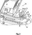
In den Figuren ist ein Teilbereich eines erfindungsgemäßen Elektrogeräts
Das Elektrogerät
Im unteren Bereich des Gehäuses
Bei einem derartigen, soweit beschriebenen Elektrogerät
Der Schaltungsträger bzw. die Platine
Das erste Trägerelement
Bei der Montage der Einzelteile des Elektrogerätes
Das soweit beschriebene Elektrogerät
Claims (10)
Translated fromGermanPriority Applications (3)
| Application Number | Priority Date | Filing Date | Title |
|---|---|---|---|
| DE102010002702ADE102010002702A1 (en) | 2010-03-09 | 2010-03-09 | Electrical appliance, in particular electric hand tool |
| CN201110054589XACN102189532A (en) | 2010-03-09 | 2011-03-08 | Electrical appliance, in particular hand-held power tool |
| US13/044,051US20110220381A1 (en) | 2010-03-09 | 2011-03-09 | Electrical appliance, in particular hand-held power tool |
Applications Claiming Priority (1)
| Application Number | Priority Date | Filing Date | Title |
|---|---|---|---|
| DE102010002702ADE102010002702A1 (en) | 2010-03-09 | 2010-03-09 | Electrical appliance, in particular electric hand tool |
Publications (1)
| Publication Number | Publication Date |
|---|---|
| DE102010002702A1true DE102010002702A1 (en) | 2011-09-15 |
Family
ID=44507656
Family Applications (1)
| Application Number | Title | Priority Date | Filing Date |
|---|---|---|---|
| DE102010002702AWithdrawnDE102010002702A1 (en) | 2010-03-09 | 2010-03-09 | Electrical appliance, in particular electric hand tool |
Country Status (3)
| Country | Link |
|---|---|
| US (1) | US20110220381A1 (en) |
| CN (1) | CN102189532A (en) |
| DE (1) | DE102010002702A1 (en) |
Families Citing this family (351)
| Publication number | Priority date | Publication date | Assignee | Title |
|---|---|---|---|---|
| US20070084897A1 (en) | 2003-05-20 | 2007-04-19 | Shelton Frederick E Iv | Articulating surgical stapling instrument incorporating a two-piece e-beam firing mechanism |
| US9060770B2 (en) | 2003-05-20 | 2015-06-23 | Ethicon Endo-Surgery, Inc. | Robotically-driven surgical instrument with E-beam driver |
| US11998198B2 (en) | 2004-07-28 | 2024-06-04 | Cilag Gmbh International | Surgical stapling instrument incorporating a two-piece E-beam firing mechanism |
| US11890012B2 (en) | 2004-07-28 | 2024-02-06 | Cilag Gmbh International | Staple cartridge comprising cartridge body and attached support |
| US8215531B2 (en) | 2004-07-28 | 2012-07-10 | Ethicon Endo-Surgery, Inc. | Surgical stapling instrument having a medical substance dispenser |
| US9072535B2 (en) | 2011-05-27 | 2015-07-07 | Ethicon Endo-Surgery, Inc. | Surgical stapling instruments with rotatable staple deployment arrangements |
| US10159482B2 (en) | 2005-08-31 | 2018-12-25 | Ethicon Llc | Fastener cartridge assembly comprising a fixed anvil and different staple heights |
| US11246590B2 (en) | 2005-08-31 | 2022-02-15 | Cilag Gmbh International | Staple cartridge including staple drivers having different unfired heights |
| US9237891B2 (en) | 2005-08-31 | 2016-01-19 | Ethicon Endo-Surgery, Inc. | Robotically-controlled surgical stapling devices that produce formed staples having different lengths |
| US7934630B2 (en) | 2005-08-31 | 2011-05-03 | Ethicon Endo-Surgery, Inc. | Staple cartridges for forming staples having differing formed staple heights |
| US11484312B2 (en) | 2005-08-31 | 2022-11-01 | Cilag Gmbh International | Staple cartridge comprising a staple driver arrangement |
| US7669746B2 (en) | 2005-08-31 | 2010-03-02 | Ethicon Endo-Surgery, Inc. | Staple cartridges for forming staples having differing formed staple heights |
| US20070106317A1 (en) | 2005-11-09 | 2007-05-10 | Shelton Frederick E Iv | Hydraulically and electrically actuated articulation joints for surgical instruments |
| US8708213B2 (en) | 2006-01-31 | 2014-04-29 | Ethicon Endo-Surgery, Inc. | Surgical instrument having a feedback system |
| US7845537B2 (en) | 2006-01-31 | 2010-12-07 | Ethicon Endo-Surgery, Inc. | Surgical instrument having recording capabilities |
| US8186555B2 (en) | 2006-01-31 | 2012-05-29 | Ethicon Endo-Surgery, Inc. | Motor-driven surgical cutting and fastening instrument with mechanical closure system |
| US20110295295A1 (en) | 2006-01-31 | 2011-12-01 | Ethicon Endo-Surgery, Inc. | Robotically-controlled surgical instrument having recording capabilities |
| US11278279B2 (en) | 2006-01-31 | 2022-03-22 | Cilag Gmbh International | Surgical instrument assembly |
| US7753904B2 (en) | 2006-01-31 | 2010-07-13 | Ethicon Endo-Surgery, Inc. | Endoscopic surgical instrument with a handle that can articulate with respect to the shaft |
| US20120292367A1 (en) | 2006-01-31 | 2012-11-22 | Ethicon Endo-Surgery, Inc. | Robotically-controlled end effector |
| US11793518B2 (en) | 2006-01-31 | 2023-10-24 | Cilag Gmbh International | Powered surgical instruments with firing system lockout arrangements |
| US11224427B2 (en) | 2006-01-31 | 2022-01-18 | Cilag Gmbh International | Surgical stapling system including a console and retraction assembly |
| US8820603B2 (en) | 2006-01-31 | 2014-09-02 | Ethicon Endo-Surgery, Inc. | Accessing data stored in a memory of a surgical instrument |
| US8992422B2 (en) | 2006-03-23 | 2015-03-31 | Ethicon Endo-Surgery, Inc. | Robotically-controlled endoscopic accessory channel |
| US8322455B2 (en) | 2006-06-27 | 2012-12-04 | Ethicon Endo-Surgery, Inc. | Manually driven surgical cutting and fastening instrument |
| US10568652B2 (en) | 2006-09-29 | 2020-02-25 | Ethicon Llc | Surgical staples having attached drivers of different heights and stapling instruments for deploying the same |
| US11980366B2 (en) | 2006-10-03 | 2024-05-14 | Cilag Gmbh International | Surgical instrument |
| US8632535B2 (en) | 2007-01-10 | 2014-01-21 | Ethicon Endo-Surgery, Inc. | Interlock and surgical instrument including same |
| US11291441B2 (en) | 2007-01-10 | 2022-04-05 | Cilag Gmbh International | Surgical instrument with wireless communication between control unit and remote sensor |
| US8684253B2 (en) | 2007-01-10 | 2014-04-01 | Ethicon Endo-Surgery, Inc. | Surgical instrument with wireless communication between a control unit of a robotic system and remote sensor |
| US20080169333A1 (en) | 2007-01-11 | 2008-07-17 | Shelton Frederick E | Surgical stapler end effector with tapered distal end |
| US11039836B2 (en) | 2007-01-11 | 2021-06-22 | Cilag Gmbh International | Staple cartridge for use with a surgical stapling instrument |
| US7673782B2 (en) | 2007-03-15 | 2010-03-09 | Ethicon Endo-Surgery, Inc. | Surgical stapling instrument having a releasable buttress material |
| US11564682B2 (en) | 2007-06-04 | 2023-01-31 | Cilag Gmbh International | Surgical stapler device |
| US8931682B2 (en) | 2007-06-04 | 2015-01-13 | Ethicon Endo-Surgery, Inc. | Robotically-controlled shaft based rotary drive systems for surgical instruments |
| US7753245B2 (en) | 2007-06-22 | 2010-07-13 | Ethicon Endo-Surgery, Inc. | Surgical stapling instruments |
| US11849941B2 (en) | 2007-06-29 | 2023-12-26 | Cilag Gmbh International | Staple cartridge having staple cavities extending at a transverse angle relative to a longitudinal cartridge axis |
| US7866527B2 (en) | 2008-02-14 | 2011-01-11 | Ethicon Endo-Surgery, Inc. | Surgical stapling apparatus with interlockable firing system |
| US7819298B2 (en) | 2008-02-14 | 2010-10-26 | Ethicon Endo-Surgery, Inc. | Surgical stapling apparatus with control features operable with one hand |
| US8636736B2 (en) | 2008-02-14 | 2014-01-28 | Ethicon Endo-Surgery, Inc. | Motorized surgical cutting and fastening instrument |
| US9179912B2 (en) | 2008-02-14 | 2015-11-10 | Ethicon Endo-Surgery, Inc. | Robotically-controlled motorized surgical cutting and fastening instrument |
| JP5410110B2 (en) | 2008-02-14 | 2014-02-05 | エシコン・エンド−サージェリィ・インコーポレイテッド | Surgical cutting / fixing instrument with RF electrode |
| US8573465B2 (en) | 2008-02-14 | 2013-11-05 | Ethicon Endo-Surgery, Inc. | Robotically-controlled surgical end effector system with rotary actuated closure systems |
| US11986183B2 (en) | 2008-02-14 | 2024-05-21 | Cilag Gmbh International | Surgical cutting and fastening instrument comprising a plurality of sensors to measure an electrical parameter |
| US9585657B2 (en) | 2008-02-15 | 2017-03-07 | Ethicon Endo-Surgery, Llc | Actuator for releasing a layer of material from a surgical end effector |
| US9005230B2 (en) | 2008-09-23 | 2015-04-14 | Ethicon Endo-Surgery, Inc. | Motorized surgical instrument |
| US11648005B2 (en) | 2008-09-23 | 2023-05-16 | Cilag Gmbh International | Robotically-controlled motorized surgical instrument with an end effector |
| US8210411B2 (en) | 2008-09-23 | 2012-07-03 | Ethicon Endo-Surgery, Inc. | Motor-driven surgical cutting instrument |
| US9386983B2 (en) | 2008-09-23 | 2016-07-12 | Ethicon Endo-Surgery, Llc | Robotically-controlled motorized surgical instrument |
| US8608045B2 (en) | 2008-10-10 | 2013-12-17 | Ethicon Endo-Sugery, Inc. | Powered surgical cutting and stapling apparatus with manually retractable firing system |
| US8517239B2 (en) | 2009-02-05 | 2013-08-27 | Ethicon Endo-Surgery, Inc. | Surgical stapling instrument comprising a magnetic element driver |
| RU2525225C2 (en) | 2009-02-06 | 2014-08-10 | Этикон Эндо-Серджери, Инк. | Improvement of drive surgical suturing instrument |
| US8851354B2 (en) | 2009-12-24 | 2014-10-07 | Ethicon Endo-Surgery, Inc. | Surgical cutting instrument that analyzes tissue thickness |
| US8220688B2 (en) | 2009-12-24 | 2012-07-17 | Ethicon Endo-Surgery, Inc. | Motor-driven surgical cutting instrument with electric actuator directional control assembly |
| US8783543B2 (en) | 2010-07-30 | 2014-07-22 | Ethicon Endo-Surgery, Inc. | Tissue acquisition arrangements and methods for surgical stapling devices |
| US11925354B2 (en) | 2010-09-30 | 2024-03-12 | Cilag Gmbh International | Staple cartridge comprising staples positioned within a compressible portion thereof |
| US9629814B2 (en) | 2010-09-30 | 2017-04-25 | Ethicon Endo-Surgery, Llc | Tissue thickness compensator configured to redistribute compressive forces |
| US12213666B2 (en) | 2010-09-30 | 2025-02-04 | Cilag Gmbh International | Tissue thickness compensator comprising layers |
| US9386988B2 (en) | 2010-09-30 | 2016-07-12 | Ethicon End-Surgery, LLC | Retainer assembly including a tissue thickness compensator |
| US9016542B2 (en) | 2010-09-30 | 2015-04-28 | Ethicon Endo-Surgery, Inc. | Staple cartridge comprising compressible distortion resistant components |
| US10945731B2 (en) | 2010-09-30 | 2021-03-16 | Ethicon Llc | Tissue thickness compensator comprising controlled release and expansion |
| US11298125B2 (en) | 2010-09-30 | 2022-04-12 | Cilag Gmbh International | Tissue stapler having a thickness compensator |
| US9788834B2 (en) | 2010-09-30 | 2017-10-17 | Ethicon Llc | Layer comprising deployable attachment members |
| US9351730B2 (en) | 2011-04-29 | 2016-05-31 | Ethicon Endo-Surgery, Llc | Tissue thickness compensator comprising channels |
| US11812965B2 (en) | 2010-09-30 | 2023-11-14 | Cilag Gmbh International | Layer of material for a surgical end effector |
| US8695866B2 (en) | 2010-10-01 | 2014-04-15 | Ethicon Endo-Surgery, Inc. | Surgical instrument having a power control circuit |
| AU2012250197B2 (en) | 2011-04-29 | 2017-08-10 | Ethicon Endo-Surgery, Inc. | Staple cartridge comprising staples positioned within a compressible portion thereof |
| US11207064B2 (en) | 2011-05-27 | 2021-12-28 | Cilag Gmbh International | Automated end effector component reloading system for use with a robotic system |
| JP5728303B2 (en)* | 2011-06-15 | 2015-06-03 | 株式会社マキタ | Impact tool |
| DE102011115008A1 (en)* | 2011-10-06 | 2013-04-11 | Wacker Neuson Produktion GmbH & Co. KG | Power tool with protective cover |
| BR112014024098B1 (en) | 2012-03-28 | 2021-05-25 | Ethicon Endo-Surgery, Inc. | staple cartridge |
| MX358135B (en) | 2012-03-28 | 2018-08-06 | Ethicon Endo Surgery Inc | Tissue thickness compensator comprising a plurality of layers. |
| DE102012104538A1 (en) | 2012-05-25 | 2013-11-28 | Gustav Klauke Gmbh | Tool |
| US9172115B2 (en) | 2012-06-12 | 2015-10-27 | Milwaukee Electric Tool Corporation | Battery pack with multiple water discharge pathways |
| US9101358B2 (en) | 2012-06-15 | 2015-08-11 | Ethicon Endo-Surgery, Inc. | Articulatable surgical instrument comprising a firing drive |
| US9408606B2 (en) | 2012-06-28 | 2016-08-09 | Ethicon Endo-Surgery, Llc | Robotically powered surgical device with manually-actuatable reversing system |
| US11278284B2 (en) | 2012-06-28 | 2022-03-22 | Cilag Gmbh International | Rotary drive arrangements for surgical instruments |
| JP6290201B2 (en) | 2012-06-28 | 2018-03-07 | エシコン・エンド−サージェリィ・インコーポレイテッドEthicon Endo−Surgery,Inc. | Lockout for empty clip cartridge |
| US9289256B2 (en) | 2012-06-28 | 2016-03-22 | Ethicon Endo-Surgery, Llc | Surgical end effectors having angled tissue-contacting surfaces |
| US9282974B2 (en) | 2012-06-28 | 2016-03-15 | Ethicon Endo-Surgery, Llc | Empty clip cartridge lockout |
| US12383267B2 (en) | 2012-06-28 | 2025-08-12 | Cilag Gmbh International | Robotically powered surgical device with manually-actuatable reversing system |
| BR112014032776B1 (en) | 2012-06-28 | 2021-09-08 | Ethicon Endo-Surgery, Inc | SURGICAL INSTRUMENT SYSTEM AND SURGICAL KIT FOR USE WITH A SURGICAL INSTRUMENT SYSTEM |
| US20140001231A1 (en) | 2012-06-28 | 2014-01-02 | Ethicon Endo-Surgery, Inc. | Firing system lockout arrangements for surgical instruments |
| JP6032400B2 (en)* | 2012-08-15 | 2016-11-30 | 日立工機株式会社 | Chainsaw |
| DE102013226248A1 (en)* | 2012-12-21 | 2014-06-26 | Robert Bosch Gmbh | Hand Tools Battery |
| BR112015021082B1 (en) | 2013-03-01 | 2022-05-10 | Ethicon Endo-Surgery, Inc | surgical instrument |
| RU2672520C2 (en) | 2013-03-01 | 2018-11-15 | Этикон Эндо-Серджери, Инк. | Hingedly turnable surgical instruments with conducting ways for signal transfer |
| US9629629B2 (en) | 2013-03-14 | 2017-04-25 | Ethicon Endo-Surgey, LLC | Control systems for surgical instruments |
| BR112015026109B1 (en) | 2013-04-16 | 2022-02-22 | Ethicon Endo-Surgery, Inc | surgical instrument |
| US9826976B2 (en) | 2013-04-16 | 2017-11-28 | Ethicon Llc | Motor driven surgical instruments with lockable dual drive shafts |
| US9775609B2 (en) | 2013-08-23 | 2017-10-03 | Ethicon Llc | Tamper proof circuit for surgical instrument battery pack |
| MX369362B (en) | 2013-08-23 | 2019-11-06 | Ethicon Endo Surgery Llc | Firing member retraction devices for powered surgical instruments. |
| BR112016021943B1 (en) | 2014-03-26 | 2022-06-14 | Ethicon Endo-Surgery, Llc | SURGICAL INSTRUMENT FOR USE BY AN OPERATOR IN A SURGICAL PROCEDURE |
| US10013049B2 (en) | 2014-03-26 | 2018-07-03 | Ethicon Llc | Power management through sleep options of segmented circuit and wake up control |
| US20150272580A1 (en) | 2014-03-26 | 2015-10-01 | Ethicon Endo-Surgery, Inc. | Verification of number of battery exchanges/procedure count |
| US12232723B2 (en) | 2014-03-26 | 2025-02-25 | Cilag Gmbh International | Systems and methods for controlling a segmented circuit |
| US10327764B2 (en) | 2014-09-26 | 2019-06-25 | Ethicon Llc | Method for creating a flexible staple line |
| BR112016023825B1 (en) | 2014-04-16 | 2022-08-02 | Ethicon Endo-Surgery, Llc | STAPLE CARTRIDGE FOR USE WITH A SURGICAL STAPLER AND STAPLE CARTRIDGE FOR USE WITH A SURGICAL INSTRUMENT |
| US20150297225A1 (en) | 2014-04-16 | 2015-10-22 | Ethicon Endo-Surgery, Inc. | Fastener cartridges including extensions having different configurations |
| CN106456176B (en) | 2014-04-16 | 2019-06-28 | 伊西康内外科有限责任公司 | Fastener Cartridge Including Extensions With Different Configurations |
| CN106456159B (en) | 2014-04-16 | 2019-03-08 | 伊西康内外科有限责任公司 | Fastener Cartridge Assembly and Nail Retainer Cover Arrangement |
| JP6268040B2 (en)* | 2014-05-27 | 2018-01-24 | 株式会社マキタ | Electric tool |
| US10040178B2 (en) | 2014-05-27 | 2018-08-07 | Makita Corporation | Power tool and rotary impact tool |
| BR112017004361B1 (en) | 2014-09-05 | 2023-04-11 | Ethicon Llc | ELECTRONIC SYSTEM FOR A SURGICAL INSTRUMENT |
| US10135242B2 (en) | 2014-09-05 | 2018-11-20 | Ethicon Llc | Smart cartridge wake up operation and data retention |
| US11311294B2 (en) | 2014-09-05 | 2022-04-26 | Cilag Gmbh International | Powered medical device including measurement of closure state of jaws |
| US10105142B2 (en) | 2014-09-18 | 2018-10-23 | Ethicon Llc | Surgical stapler with plurality of cutting elements |
| CN107427300B (en) | 2014-09-26 | 2020-12-04 | 伊西康有限责任公司 | Surgical suture buttresses and auxiliary materials |
| US11523821B2 (en) | 2014-09-26 | 2022-12-13 | Cilag Gmbh International | Method for creating a flexible staple line |
| US9924944B2 (en) | 2014-10-16 | 2018-03-27 | Ethicon Llc | Staple cartridge comprising an adjunct material |
| US11141153B2 (en) | 2014-10-29 | 2021-10-12 | Cilag Gmbh International | Staple cartridges comprising driver arrangements |
| US10517594B2 (en) | 2014-10-29 | 2019-12-31 | Ethicon Llc | Cartridge assemblies for surgical staplers |
| US9844376B2 (en) | 2014-11-06 | 2017-12-19 | Ethicon Llc | Staple cartridge comprising a releasable adjunct material |
| US10736636B2 (en) | 2014-12-10 | 2020-08-11 | Ethicon Llc | Articulatable surgical instrument system |
| US9844375B2 (en) | 2014-12-18 | 2017-12-19 | Ethicon Llc | Drive arrangements for articulatable surgical instruments |
| MX389118B (en) | 2014-12-18 | 2025-03-20 | Ethicon Llc | SURGICAL INSTRUMENT WITH AN ANVIL THAT CAN BE SELECTIVELY MOVED ON A DISCRETE, NON-MOBILE AXIS RELATIVE TO A STAPLE CARTRIDGE. |
| US9987000B2 (en) | 2014-12-18 | 2018-06-05 | Ethicon Llc | Surgical instrument assembly comprising a flexible articulation system |
| US10085748B2 (en) | 2014-12-18 | 2018-10-02 | Ethicon Llc | Locking arrangements for detachable shaft assemblies with articulatable surgical end effectors |
| US9844374B2 (en) | 2014-12-18 | 2017-12-19 | Ethicon Llc | Surgical instrument systems comprising an articulatable end effector and means for adjusting the firing stroke of a firing member |
| US9943309B2 (en) | 2014-12-18 | 2018-04-17 | Ethicon Llc | Surgical instruments with articulatable end effectors and movable firing beam support arrangements |
| US11154301B2 (en) | 2015-02-27 | 2021-10-26 | Cilag Gmbh International | Modular stapling assembly |
| JP2020121162A (en) | 2015-03-06 | 2020-08-13 | エシコン エルエルシーEthicon LLC | Time dependent evaluation of sensor data to determine stability element, creep element and viscoelastic element of measurement |
| US10548504B2 (en) | 2015-03-06 | 2020-02-04 | Ethicon Llc | Overlaid multi sensor radio frequency (RF) electrode system to measure tissue compression |
| US9993248B2 (en) | 2015-03-06 | 2018-06-12 | Ethicon Endo-Surgery, Llc | Smart sensors with local signal processing |
| US10441279B2 (en) | 2015-03-06 | 2019-10-15 | Ethicon Llc | Multiple level thresholds to modify operation of powered surgical instruments |
| US10245033B2 (en) | 2015-03-06 | 2019-04-02 | Ethicon Llc | Surgical instrument comprising a lockable battery housing |
| US10433844B2 (en) | 2015-03-31 | 2019-10-08 | Ethicon Llc | Surgical instrument with selectively disengageable threaded drive systems |
| US10238386B2 (en) | 2015-09-23 | 2019-03-26 | Ethicon Llc | Surgical stapler having motor control based on an electrical parameter related to a motor current |
| US10105139B2 (en) | 2015-09-23 | 2018-10-23 | Ethicon Llc | Surgical stapler having downstream current-based motor control |
| US10299878B2 (en) | 2015-09-25 | 2019-05-28 | Ethicon Llc | Implantable adjunct systems for determining adjunct skew |
| US10433846B2 (en) | 2015-09-30 | 2019-10-08 | Ethicon Llc | Compressible adjunct with crossing spacer fibers |
| US11890015B2 (en) | 2015-09-30 | 2024-02-06 | Cilag Gmbh International | Compressible adjunct with crossing spacer fibers |
| US10478188B2 (en) | 2015-09-30 | 2019-11-19 | Ethicon Llc | Implantable layer comprising a constricted configuration |
| US10404136B2 (en)* | 2015-10-14 | 2019-09-03 | Black & Decker Inc. | Power tool with separate motor case compartment |
| US10368865B2 (en) | 2015-12-30 | 2019-08-06 | Ethicon Llc | Mechanisms for compensating for drivetrain failure in powered surgical instruments |
| US10292704B2 (en) | 2015-12-30 | 2019-05-21 | Ethicon Llc | Mechanisms for compensating for battery pack failure in powered surgical instruments |
| US10265068B2 (en) | 2015-12-30 | 2019-04-23 | Ethicon Llc | Surgical instruments with separable motors and motor control circuits |
| BR112018016098B1 (en) | 2016-02-09 | 2023-02-23 | Ethicon Llc | SURGICAL INSTRUMENT |
| US11213293B2 (en) | 2016-02-09 | 2022-01-04 | Cilag Gmbh International | Articulatable surgical instruments with single articulation link arrangements |
| US11224426B2 (en) | 2016-02-12 | 2022-01-18 | Cilag Gmbh International | Mechanisms for compensating for drivetrain failure in powered surgical instruments |
| US10448948B2 (en) | 2016-02-12 | 2019-10-22 | Ethicon Llc | Mechanisms for compensating for drivetrain failure in powered surgical instruments |
| US10357247B2 (en) | 2016-04-15 | 2019-07-23 | Ethicon Llc | Surgical instrument with multiple program responses during a firing motion |
| US10335145B2 (en) | 2016-04-15 | 2019-07-02 | Ethicon Llc | Modular surgical instrument with configurable operating mode |
| US11179150B2 (en) | 2016-04-15 | 2021-11-23 | Cilag Gmbh International | Systems and methods for controlling a surgical stapling and cutting instrument |
| US11607239B2 (en) | 2016-04-15 | 2023-03-21 | Cilag Gmbh International | Systems and methods for controlling a surgical stapling and cutting instrument |
| US10492783B2 (en) | 2016-04-15 | 2019-12-03 | Ethicon, Llc | Surgical instrument with improved stop/start control during a firing motion |
| US10426467B2 (en) | 2016-04-15 | 2019-10-01 | Ethicon Llc | Surgical instrument with detection sensors |
| US10828028B2 (en) | 2016-04-15 | 2020-11-10 | Ethicon Llc | Surgical instrument with multiple program responses during a firing motion |
| US10456137B2 (en) | 2016-04-15 | 2019-10-29 | Ethicon Llc | Staple formation detection mechanisms |
| US11317917B2 (en) | 2016-04-18 | 2022-05-03 | Cilag Gmbh International | Surgical stapling system comprising a lockable firing assembly |
| US20170296173A1 (en) | 2016-04-18 | 2017-10-19 | Ethicon Endo-Surgery, Llc | Method for operating a surgical instrument |
| US10363037B2 (en) | 2016-04-18 | 2019-07-30 | Ethicon Llc | Surgical instrument system comprising a magnetic lockout |
| EP3269514A1 (en)* | 2016-07-11 | 2018-01-17 | HILTI Aktiengesellschaft | Setting device |
| US10500000B2 (en) | 2016-08-16 | 2019-12-10 | Ethicon Llc | Surgical tool with manual control of end effector jaws |
| JP6342974B2 (en)* | 2016-11-24 | 2018-06-13 | ファナック株式会社 | Manual pulse generator |
| US10542982B2 (en) | 2016-12-21 | 2020-01-28 | Ethicon Llc | Shaft assembly comprising first and second articulation lockouts |
| US20180168615A1 (en) | 2016-12-21 | 2018-06-21 | Ethicon Endo-Surgery, Llc | Method of deforming staples from two different types of staple cartridges with the same surgical stapling instrument |
| MX2019007295A (en) | 2016-12-21 | 2019-10-15 | Ethicon Llc | Surgical instrument system comprising an end effector lockout and a firing assembly lockout. |
| JP2020501815A (en) | 2016-12-21 | 2020-01-23 | エシコン エルエルシーEthicon LLC | Surgical stapling system |
| JP7010957B2 (en) | 2016-12-21 | 2022-01-26 | エシコン エルエルシー | Shaft assembly with lockout |
| JP6983893B2 (en) | 2016-12-21 | 2021-12-17 | エシコン エルエルシーEthicon LLC | Lockout configuration for surgical end effectors and replaceable tool assemblies |
| US11419606B2 (en) | 2016-12-21 | 2022-08-23 | Cilag Gmbh International | Shaft assembly comprising a clutch configured to adapt the output of a rotary firing member to two different systems |
| US11090048B2 (en) | 2016-12-21 | 2021-08-17 | Cilag Gmbh International | Method for resetting a fuse of a surgical instrument shaft |
| JP7010956B2 (en) | 2016-12-21 | 2022-01-26 | エシコン エルエルシー | How to staple tissue |
| US20180168625A1 (en) | 2016-12-21 | 2018-06-21 | Ethicon Endo-Surgery, Llc | Surgical stapling instruments with smart staple cartridges |
| US10813638B2 (en) | 2016-12-21 | 2020-10-27 | Ethicon Llc | Surgical end effectors with expandable tissue stop arrangements |
| US10973516B2 (en) | 2016-12-21 | 2021-04-13 | Ethicon Llc | Surgical end effectors and adaptable firing members therefor |
| US10980536B2 (en) | 2016-12-21 | 2021-04-20 | Ethicon Llc | No-cartridge and spent cartridge lockout arrangements for surgical staplers |
| CN110087565A (en) | 2016-12-21 | 2019-08-02 | 爱惜康有限责任公司 | Surgical stapling system |
| US10582928B2 (en) | 2016-12-21 | 2020-03-10 | Ethicon Llc | Articulation lock arrangements for locking an end effector in an articulated position in response to actuation of a jaw closure system |
| WO2018158488A1 (en)* | 2017-02-28 | 2018-09-07 | Mirka Ltd | Cooling arrangement for a power tool and power tool electronics |
| US11653914B2 (en) | 2017-06-20 | 2023-05-23 | Cilag Gmbh International | Systems and methods for controlling motor velocity of a surgical stapling and cutting instrument according to articulation angle of end effector |
| US10307170B2 (en) | 2017-06-20 | 2019-06-04 | Ethicon Llc | Method for closed loop control of motor velocity of a surgical stapling and cutting instrument |
| US11382638B2 (en) | 2017-06-20 | 2022-07-12 | Cilag Gmbh International | Closed loop feedback control of motor velocity of a surgical stapling and cutting instrument based on measured time over a specified displacement distance |
| US11090046B2 (en) | 2017-06-20 | 2021-08-17 | Cilag Gmbh International | Systems and methods for controlling displacement member motion of a surgical stapling and cutting instrument |
| US11071554B2 (en) | 2017-06-20 | 2021-07-27 | Cilag Gmbh International | Closed loop feedback control of motor velocity of a surgical stapling and cutting instrument based on magnitude of velocity error measurements |
| US10779820B2 (en) | 2017-06-20 | 2020-09-22 | Ethicon Llc | Systems and methods for controlling motor speed according to user input for a surgical instrument |
| US10881399B2 (en) | 2017-06-20 | 2021-01-05 | Ethicon Llc | Techniques for adaptive control of motor velocity of a surgical stapling and cutting instrument |
| US11517325B2 (en) | 2017-06-20 | 2022-12-06 | Cilag Gmbh International | Closed loop feedback control of motor velocity of a surgical stapling and cutting instrument based on measured displacement distance traveled over a specified time interval |
| US11324503B2 (en) | 2017-06-27 | 2022-05-10 | Cilag Gmbh International | Surgical firing member arrangements |
| US11266405B2 (en) | 2017-06-27 | 2022-03-08 | Cilag Gmbh International | Surgical anvil manufacturing methods |
| US11090049B2 (en) | 2017-06-27 | 2021-08-17 | Cilag Gmbh International | Staple forming pocket arrangements |
| US10993716B2 (en) | 2017-06-27 | 2021-05-04 | Ethicon Llc | Surgical anvil arrangements |
| USD906355S1 (en) | 2017-06-28 | 2020-12-29 | Ethicon Llc | Display screen or portion thereof with a graphical user interface for a surgical instrument |
| US11259805B2 (en) | 2017-06-28 | 2022-03-01 | Cilag Gmbh International | Surgical instrument comprising firing member supports |
| US11484310B2 (en) | 2017-06-28 | 2022-11-01 | Cilag Gmbh International | Surgical instrument comprising a shaft including a closure tube profile |
| EP3420947B1 (en) | 2017-06-28 | 2022-05-25 | Cilag GmbH International | Surgical instrument comprising selectively actuatable rotatable couplers |
| US11246592B2 (en) | 2017-06-28 | 2022-02-15 | Cilag Gmbh International | Surgical instrument comprising an articulation system lockable to a frame |
| US10758232B2 (en) | 2017-06-28 | 2020-09-01 | Ethicon Llc | Surgical instrument with positive jaw opening features |
| US10765427B2 (en) | 2017-06-28 | 2020-09-08 | Ethicon Llc | Method for articulating a surgical instrument |
| US11564686B2 (en) | 2017-06-28 | 2023-01-31 | Cilag Gmbh International | Surgical shaft assemblies with flexible interfaces |
| US10932772B2 (en) | 2017-06-29 | 2021-03-02 | Ethicon Llc | Methods for closed loop velocity control for robotic surgical instrument |
| US11471155B2 (en) | 2017-08-03 | 2022-10-18 | Cilag Gmbh International | Surgical system bailout |
| US11944300B2 (en) | 2017-08-03 | 2024-04-02 | Cilag Gmbh International | Method for operating a surgical system bailout |
| US11974742B2 (en) | 2017-08-03 | 2024-05-07 | Cilag Gmbh International | Surgical system comprising an articulation bailout |
| US11304695B2 (en) | 2017-08-03 | 2022-04-19 | Cilag Gmbh International | Surgical system shaft interconnection |
| US11331099B2 (en) | 2017-09-01 | 2022-05-17 | Rev Medica, Inc. | Surgical stapler with removable power pack and interchangeable battery pack |
| US10695060B2 (en)* | 2017-09-01 | 2020-06-30 | RevMedica, Inc. | Loadable power pack for surgical instruments |
| US10966720B2 (en) | 2017-09-01 | 2021-04-06 | RevMedica, Inc. | Surgical stapler with removable power pack |
| US11399829B2 (en) | 2017-09-29 | 2022-08-02 | Cilag Gmbh International | Systems and methods of initiating a power shutdown mode for a surgical instrument |
| US10743872B2 (en) | 2017-09-29 | 2020-08-18 | Ethicon Llc | System and methods for controlling a display of a surgical instrument |
| US11090075B2 (en) | 2017-10-30 | 2021-08-17 | Cilag Gmbh International | Articulation features for surgical end effector |
| US11134944B2 (en) | 2017-10-30 | 2021-10-05 | Cilag Gmbh International | Surgical stapler knife motion controls |
| US10842490B2 (en) | 2017-10-31 | 2020-11-24 | Ethicon Llc | Cartridge body design with force reduction based on firing completion |
| US10779826B2 (en) | 2017-12-15 | 2020-09-22 | Ethicon Llc | Methods of operating surgical end effectors |
| US11197670B2 (en) | 2017-12-15 | 2021-12-14 | Cilag Gmbh International | Surgical end effectors with pivotal jaws configured to touch at their respective distal ends when fully closed |
| US11071543B2 (en) | 2017-12-15 | 2021-07-27 | Cilag Gmbh International | Surgical end effectors with clamping assemblies configured to increase jaw aperture ranges |
| US10835330B2 (en) | 2017-12-19 | 2020-11-17 | Ethicon Llc | Method for determining the position of a rotatable jaw of a surgical instrument attachment assembly |
| US12336705B2 (en) | 2017-12-21 | 2025-06-24 | Cilag Gmbh International | Continuous use self-propelled stapling instrument |
| US11179151B2 (en) | 2017-12-21 | 2021-11-23 | Cilag Gmbh International | Surgical instrument comprising a display |
| US11076853B2 (en) | 2017-12-21 | 2021-08-03 | Cilag Gmbh International | Systems and methods of displaying a knife position during transection for a surgical instrument |
| US11311290B2 (en) | 2017-12-21 | 2022-04-26 | Cilag Gmbh International | Surgical instrument comprising an end effector dampener |
| US20200054321A1 (en) | 2018-08-20 | 2020-02-20 | Ethicon Llc | Surgical instruments with progressive jaw closure arrangements |
| US11207065B2 (en) | 2018-08-20 | 2021-12-28 | Cilag Gmbh International | Method for fabricating surgical stapler anvils |
| US11324501B2 (en) | 2018-08-20 | 2022-05-10 | Cilag Gmbh International | Surgical stapling devices with improved closure members |
| US11253256B2 (en) | 2018-08-20 | 2022-02-22 | Cilag Gmbh International | Articulatable motor powered surgical instruments with dedicated articulation motor arrangements |
| US11045192B2 (en) | 2018-08-20 | 2021-06-29 | Cilag Gmbh International | Fabricating techniques for surgical stapler anvils |
| US11291440B2 (en) | 2018-08-20 | 2022-04-05 | Cilag Gmbh International | Method for operating a powered articulatable surgical instrument |
| US11696761B2 (en) | 2019-03-25 | 2023-07-11 | Cilag Gmbh International | Firing drive arrangements for surgical systems |
| US11147553B2 (en) | 2019-03-25 | 2021-10-19 | Cilag Gmbh International | Firing drive arrangements for surgical systems |
| US11172929B2 (en) | 2019-03-25 | 2021-11-16 | Cilag Gmbh International | Articulation drive arrangements for surgical systems |
| US11147551B2 (en) | 2019-03-25 | 2021-10-19 | Cilag Gmbh International | Firing drive arrangements for surgical systems |
| US11432816B2 (en) | 2019-04-30 | 2022-09-06 | Cilag Gmbh International | Articulation pin for a surgical instrument |
| US11648009B2 (en) | 2019-04-30 | 2023-05-16 | Cilag Gmbh International | Rotatable jaw tip for a surgical instrument |
| US11253254B2 (en) | 2019-04-30 | 2022-02-22 | Cilag Gmbh International | Shaft rotation actuator on a surgical instrument |
| US11903581B2 (en) | 2019-04-30 | 2024-02-20 | Cilag Gmbh International | Methods for stapling tissue using a surgical instrument |
| US11471157B2 (en) | 2019-04-30 | 2022-10-18 | Cilag Gmbh International | Articulation control mapping for a surgical instrument |
| US11426251B2 (en) | 2019-04-30 | 2022-08-30 | Cilag Gmbh International | Articulation directional lights on a surgical instrument |
| US11452528B2 (en) | 2019-04-30 | 2022-09-27 | Cilag Gmbh International | Articulation actuators for a surgical instrument |
| US11259803B2 (en) | 2019-06-28 | 2022-03-01 | Cilag Gmbh International | Surgical stapling system having an information encryption protocol |
| US11660163B2 (en) | 2019-06-28 | 2023-05-30 | Cilag Gmbh International | Surgical system with RFID tags for updating motor assembly parameters |
| US11224497B2 (en) | 2019-06-28 | 2022-01-18 | Cilag Gmbh International | Surgical systems with multiple RFID tags |
| US11246678B2 (en) | 2019-06-28 | 2022-02-15 | Cilag Gmbh International | Surgical stapling system having a frangible RFID tag |
| US11771419B2 (en) | 2019-06-28 | 2023-10-03 | Cilag Gmbh International | Packaging for a replaceable component of a surgical stapling system |
| US11853835B2 (en) | 2019-06-28 | 2023-12-26 | Cilag Gmbh International | RFID identification systems for surgical instruments |
| US11241235B2 (en) | 2019-06-28 | 2022-02-08 | Cilag Gmbh International | Method of using multiple RFID chips with a surgical assembly |
| US11684434B2 (en) | 2019-06-28 | 2023-06-27 | Cilag Gmbh International | Surgical RFID assemblies for instrument operational setting control |
| US11426167B2 (en) | 2019-06-28 | 2022-08-30 | Cilag Gmbh International | Mechanisms for proper anvil attachment surgical stapling head assembly |
| US11298132B2 (en) | 2019-06-28 | 2022-04-12 | Cilag GmbH Inlernational | Staple cartridge including a honeycomb extension |
| US12004740B2 (en) | 2019-06-28 | 2024-06-11 | Cilag Gmbh International | Surgical stapling system having an information decryption protocol |
| US11399837B2 (en) | 2019-06-28 | 2022-08-02 | Cilag Gmbh International | Mechanisms for motor control adjustments of a motorized surgical instrument |
| US11291451B2 (en) | 2019-06-28 | 2022-04-05 | Cilag Gmbh International | Surgical instrument with battery compatibility verification functionality |
| US11638587B2 (en) | 2019-06-28 | 2023-05-02 | Cilag Gmbh International | RFID identification systems for surgical instruments |
| US11219455B2 (en) | 2019-06-28 | 2022-01-11 | Cilag Gmbh International | Surgical instrument including a lockout key |
| US11376098B2 (en) | 2019-06-28 | 2022-07-05 | Cilag Gmbh International | Surgical instrument system comprising an RFID system |
| US11051807B2 (en) | 2019-06-28 | 2021-07-06 | Cilag Gmbh International | Packaging assembly including a particulate trap |
| US11478241B2 (en) | 2019-06-28 | 2022-10-25 | Cilag Gmbh International | Staple cartridge including projections |
| US20200405307A1 (en)* | 2019-06-28 | 2020-12-31 | Ethicon Llc | Control circuit comprising a coating |
| US11553971B2 (en) | 2019-06-28 | 2023-01-17 | Cilag Gmbh International | Surgical RFID assemblies for display and communication |
| US11497492B2 (en) | 2019-06-28 | 2022-11-15 | Cilag Gmbh International | Surgical instrument including an articulation lock |
| US11464601B2 (en) | 2019-06-28 | 2022-10-11 | Cilag Gmbh International | Surgical instrument comprising an RFID system for tracking a movable component |
| US11523822B2 (en) | 2019-06-28 | 2022-12-13 | Cilag Gmbh International | Battery pack including a circuit interrupter |
| US11298127B2 (en) | 2019-06-28 | 2022-04-12 | Cilag GmbH Interational | Surgical stapling system having a lockout mechanism for an incompatible cartridge |
| US11627959B2 (en) | 2019-06-28 | 2023-04-18 | Cilag Gmbh International | Surgical instruments including manual and powered system lockouts |
| US12279771B2 (en) | 2019-07-19 | 2025-04-22 | RevMedica, Inc. | Power pack for activating surgical instruments and providing user feedback |
| US12290257B2 (en) | 2019-07-19 | 2025-05-06 | RevMedica, Inc. | Surgical clip applier with removable power pack |
| US12279770B2 (en) | 2019-07-19 | 2025-04-22 | RevMedica, Inc. | Power pack for activating surgical instruments and providing user feedback |
| EP3998960A4 (en) | 2019-07-19 | 2022-12-14 | Revmedica, Inc. | Surgical stapler with removable power pack |
| US12357307B2 (en) | 2022-05-13 | 2025-07-15 | RevMedica, Inc. | Power pack for activating surgical instruments and providing user feedback |
| EP3822035A1 (en)* | 2019-11-14 | 2021-05-19 | Hilti Aktiengesellschaft | Handle device for a machine tool |
| US11446029B2 (en) | 2019-12-19 | 2022-09-20 | Cilag Gmbh International | Staple cartridge comprising projections extending from a curved deck surface |
| US11701111B2 (en) | 2019-12-19 | 2023-07-18 | Cilag Gmbh International | Method for operating a surgical stapling instrument |
| US11234698B2 (en) | 2019-12-19 | 2022-02-01 | Cilag Gmbh International | Stapling system comprising a clamp lockout and a firing lockout |
| US11576672B2 (en) | 2019-12-19 | 2023-02-14 | Cilag Gmbh International | Surgical instrument comprising a closure system including a closure member and an opening member driven by a drive screw |
| US11464512B2 (en) | 2019-12-19 | 2022-10-11 | Cilag Gmbh International | Staple cartridge comprising a curved deck surface |
| US11291447B2 (en) | 2019-12-19 | 2022-04-05 | Cilag Gmbh International | Stapling instrument comprising independent jaw closing and staple firing systems |
| US12035913B2 (en) | 2019-12-19 | 2024-07-16 | Cilag Gmbh International | Staple cartridge comprising a deployable knife |
| US11304696B2 (en) | 2019-12-19 | 2022-04-19 | Cilag Gmbh International | Surgical instrument comprising a powered articulation system |
| US11911032B2 (en) | 2019-12-19 | 2024-02-27 | Cilag Gmbh International | Staple cartridge comprising a seating cam |
| US11607219B2 (en) | 2019-12-19 | 2023-03-21 | Cilag Gmbh International | Staple cartridge comprising a detachable tissue cutting knife |
| US11559304B2 (en) | 2019-12-19 | 2023-01-24 | Cilag Gmbh International | Surgical instrument comprising a rapid closure mechanism |
| US11529139B2 (en) | 2019-12-19 | 2022-12-20 | Cilag Gmbh International | Motor driven surgical instrument |
| US11844520B2 (en) | 2019-12-19 | 2023-12-19 | Cilag Gmbh International | Staple cartridge comprising driver retention members |
| US11504122B2 (en) | 2019-12-19 | 2022-11-22 | Cilag Gmbh International | Surgical instrument comprising a nested firing member |
| US11529137B2 (en) | 2019-12-19 | 2022-12-20 | Cilag Gmbh International | Staple cartridge comprising driver retention members |
| US11931033B2 (en) | 2019-12-19 | 2024-03-19 | Cilag Gmbh International | Staple cartridge comprising a latch lockout |
| USD975850S1 (en) | 2020-06-02 | 2023-01-17 | Cilag Gmbh International | Staple cartridge |
| USD974560S1 (en) | 2020-06-02 | 2023-01-03 | Cilag Gmbh International | Staple cartridge |
| USD967421S1 (en) | 2020-06-02 | 2022-10-18 | Cilag Gmbh International | Staple cartridge |
| USD975851S1 (en) | 2020-06-02 | 2023-01-17 | Cilag Gmbh International | Staple cartridge |
| USD975278S1 (en) | 2020-06-02 | 2023-01-10 | Cilag Gmbh International | Staple cartridge |
| USD976401S1 (en) | 2020-06-02 | 2023-01-24 | Cilag Gmbh International | Staple cartridge |
| USD966512S1 (en) | 2020-06-02 | 2022-10-11 | Cilag Gmbh International | Staple cartridge |
| US11871925B2 (en) | 2020-07-28 | 2024-01-16 | Cilag Gmbh International | Surgical instruments with dual spherical articulation joint arrangements |
| US11931025B2 (en) | 2020-10-29 | 2024-03-19 | Cilag Gmbh International | Surgical instrument comprising a releasable closure drive lock |
| US11896217B2 (en) | 2020-10-29 | 2024-02-13 | Cilag Gmbh International | Surgical instrument comprising an articulation lock |
| US11717289B2 (en) | 2020-10-29 | 2023-08-08 | Cilag Gmbh International | Surgical instrument comprising an indicator which indicates that an articulation drive is actuatable |
| US11452526B2 (en) | 2020-10-29 | 2022-09-27 | Cilag Gmbh International | Surgical instrument comprising a staged voltage regulation start-up system |
| US12053175B2 (en) | 2020-10-29 | 2024-08-06 | Cilag Gmbh International | Surgical instrument comprising a stowed closure actuator stop |
| USD980425S1 (en) | 2020-10-29 | 2023-03-07 | Cilag Gmbh International | Surgical instrument assembly |
| US11779330B2 (en) | 2020-10-29 | 2023-10-10 | Cilag Gmbh International | Surgical instrument comprising a jaw alignment system |
| US11517390B2 (en) | 2020-10-29 | 2022-12-06 | Cilag Gmbh International | Surgical instrument comprising a limited travel switch |
| US11617577B2 (en) | 2020-10-29 | 2023-04-04 | Cilag Gmbh International | Surgical instrument comprising a sensor configured to sense whether an articulation drive of the surgical instrument is actuatable |
| US11844518B2 (en) | 2020-10-29 | 2023-12-19 | Cilag Gmbh International | Method for operating a surgical instrument |
| US11534259B2 (en) | 2020-10-29 | 2022-12-27 | Cilag Gmbh International | Surgical instrument comprising an articulation indicator |
| USD1013170S1 (en) | 2020-10-29 | 2024-01-30 | Cilag Gmbh International | Surgical instrument assembly |
| US11627960B2 (en) | 2020-12-02 | 2023-04-18 | Cilag Gmbh International | Powered surgical instruments with smart reload with separately attachable exteriorly mounted wiring connections |
| US11944296B2 (en) | 2020-12-02 | 2024-04-02 | Cilag Gmbh International | Powered surgical instruments with external connectors |
| US11678882B2 (en) | 2020-12-02 | 2023-06-20 | Cilag Gmbh International | Surgical instruments with interactive features to remedy incidental sled movements |
| US11653915B2 (en) | 2020-12-02 | 2023-05-23 | Cilag Gmbh International | Surgical instruments with sled location detection and adjustment features |
| US11890010B2 (en) | 2020-12-02 | 2024-02-06 | Cllag GmbH International | Dual-sided reinforced reload for surgical instruments |
| US11744581B2 (en) | 2020-12-02 | 2023-09-05 | Cilag Gmbh International | Powered surgical instruments with multi-phase tissue treatment |
| US11737751B2 (en) | 2020-12-02 | 2023-08-29 | Cilag Gmbh International | Devices and methods of managing energy dissipated within sterile barriers of surgical instrument housings |
| US11653920B2 (en) | 2020-12-02 | 2023-05-23 | Cilag Gmbh International | Powered surgical instruments with communication interfaces through sterile barrier |
| US20220167982A1 (en)* | 2020-12-02 | 2022-06-02 | Ethicon Llc | Surgical instruments with electrical connectors for power transmission across sterile barrier |
| US11849943B2 (en) | 2020-12-02 | 2023-12-26 | Cilag Gmbh International | Surgical instrument with cartridge release mechanisms |
| US11925349B2 (en) | 2021-02-26 | 2024-03-12 | Cilag Gmbh International | Adjustment to transfer parameters to improve available power |
| US11749877B2 (en) | 2021-02-26 | 2023-09-05 | Cilag Gmbh International | Stapling instrument comprising a signal antenna |
| US11751869B2 (en) | 2021-02-26 | 2023-09-12 | Cilag Gmbh International | Monitoring of multiple sensors over time to detect moving characteristics of tissue |
| US11950779B2 (en) | 2021-02-26 | 2024-04-09 | Cilag Gmbh International | Method of powering and communicating with a staple cartridge |
| US11701113B2 (en) | 2021-02-26 | 2023-07-18 | Cilag Gmbh International | Stapling instrument comprising a separate power antenna and a data transfer antenna |
| US11980362B2 (en) | 2021-02-26 | 2024-05-14 | Cilag Gmbh International | Surgical instrument system comprising a power transfer coil |
| US11730473B2 (en) | 2021-02-26 | 2023-08-22 | Cilag Gmbh International | Monitoring of manufacturing life-cycle |
| US12324580B2 (en) | 2021-02-26 | 2025-06-10 | Cilag Gmbh International | Method of powering and communicating with a staple cartridge |
| US11793514B2 (en) | 2021-02-26 | 2023-10-24 | Cilag Gmbh International | Staple cartridge comprising sensor array which may be embedded in cartridge body |
| US12108951B2 (en) | 2021-02-26 | 2024-10-08 | Cilag Gmbh International | Staple cartridge comprising a sensing array and a temperature control system |
| US11812964B2 (en) | 2021-02-26 | 2023-11-14 | Cilag Gmbh International | Staple cartridge comprising a power management circuit |
| US11696757B2 (en) | 2021-02-26 | 2023-07-11 | Cilag Gmbh International | Monitoring of internal systems to detect and track cartridge motion status |
| US11950777B2 (en) | 2021-02-26 | 2024-04-09 | Cilag Gmbh International | Staple cartridge comprising an information access control system |
| US11723657B2 (en) | 2021-02-26 | 2023-08-15 | Cilag Gmbh International | Adjustable communication based on available bandwidth and power capacity |
| US11744583B2 (en) | 2021-02-26 | 2023-09-05 | Cilag Gmbh International | Distal communication array to tune frequency of RF systems |
| US12178535B2 (en) | 2021-03-01 | 2024-12-31 | RevMedica, Inc. | Power pack for activating surgical instruments |
| US11826042B2 (en) | 2021-03-22 | 2023-11-28 | Cilag Gmbh International | Surgical instrument comprising a firing drive including a selectable leverage mechanism |
| US11826012B2 (en) | 2021-03-22 | 2023-11-28 | Cilag Gmbh International | Stapling instrument comprising a pulsed motor-driven firing rack |
| US11737749B2 (en) | 2021-03-22 | 2023-08-29 | Cilag Gmbh International | Surgical stapling instrument comprising a retraction system |
| US11759202B2 (en) | 2021-03-22 | 2023-09-19 | Cilag Gmbh International | Staple cartridge comprising an implantable layer |
| US11717291B2 (en) | 2021-03-22 | 2023-08-08 | Cilag Gmbh International | Staple cartridge comprising staples configured to apply different tissue compression |
| US11806011B2 (en) | 2021-03-22 | 2023-11-07 | Cilag Gmbh International | Stapling instrument comprising tissue compression systems |
| US11723658B2 (en) | 2021-03-22 | 2023-08-15 | Cilag Gmbh International | Staple cartridge comprising a firing lockout |
| US11903582B2 (en) | 2021-03-24 | 2024-02-20 | Cilag Gmbh International | Leveraging surfaces for cartridge installation |
| US11786243B2 (en) | 2021-03-24 | 2023-10-17 | Cilag Gmbh International | Firing members having flexible portions for adapting to a load during a surgical firing stroke |
| US11944336B2 (en) | 2021-03-24 | 2024-04-02 | Cilag Gmbh International | Joint arrangements for multi-planar alignment and support of operational drive shafts in articulatable surgical instruments |
| US11744603B2 (en) | 2021-03-24 | 2023-09-05 | Cilag Gmbh International | Multi-axis pivot joints for surgical instruments and methods for manufacturing same |
| US11832816B2 (en) | 2021-03-24 | 2023-12-05 | Cilag Gmbh International | Surgical stapling assembly comprising nonplanar staples and planar staples |
| US11896218B2 (en) | 2021-03-24 | 2024-02-13 | Cilag Gmbh International | Method of using a powered stapling device |
| US11793516B2 (en) | 2021-03-24 | 2023-10-24 | Cilag Gmbh International | Surgical staple cartridge comprising longitudinal support beam |
| US11849944B2 (en) | 2021-03-24 | 2023-12-26 | Cilag Gmbh International | Drivers for fastener cartridge assemblies having rotary drive screws |
| US11896219B2 (en) | 2021-03-24 | 2024-02-13 | Cilag Gmbh International | Mating features between drivers and underside of a cartridge deck |
| US11786239B2 (en) | 2021-03-24 | 2023-10-17 | Cilag Gmbh International | Surgical instrument articulation joint arrangements comprising multiple moving linkage features |
| US11849945B2 (en) | 2021-03-24 | 2023-12-26 | Cilag Gmbh International | Rotary-driven surgical stapling assembly comprising eccentrically driven firing member |
| US11857183B2 (en) | 2021-03-24 | 2024-01-02 | Cilag Gmbh International | Stapling assembly components having metal substrates and plastic bodies |
| US12102323B2 (en) | 2021-03-24 | 2024-10-01 | Cilag Gmbh International | Rotary-driven surgical stapling assembly comprising a floatable component |
| US11826047B2 (en) | 2021-05-28 | 2023-11-28 | Cilag Gmbh International | Stapling instrument comprising jaw mounts |
| US11980363B2 (en) | 2021-10-18 | 2024-05-14 | Cilag Gmbh International | Row-to-row staple array variations |
| US11877745B2 (en) | 2021-10-18 | 2024-01-23 | Cilag Gmbh International | Surgical stapling assembly having longitudinally-repeating staple leg clusters |
| US12239317B2 (en) | 2021-10-18 | 2025-03-04 | Cilag Gmbh International | Anvil comprising an arrangement of forming pockets proximal to tissue stop |
| US11957337B2 (en) | 2021-10-18 | 2024-04-16 | Cilag Gmbh International | Surgical stapling assembly with offset ramped drive surfaces |
| US12432790B2 (en) | 2021-10-28 | 2025-09-30 | Cilag Gmbh International | Method and device for transmitting UART communications over a security short range wireless communication |
| US11937816B2 (en) | 2021-10-28 | 2024-03-26 | Cilag Gmbh International | Electrical lead arrangements for surgical instruments |
| US12089841B2 (en) | 2021-10-28 | 2024-09-17 | Cilag CmbH International | Staple cartridge identification systems |
| CN118144048A (en)* | 2022-12-06 | 2024-06-07 | 莱克电气绿能科技(苏州)有限公司 | A planing device |
Family Cites Families (61)
| Publication number | Priority date | Publication date | Assignee | Title |
|---|---|---|---|---|
| US4427077A (en)* | 1979-10-25 | 1984-01-24 | Rockwell International Corporation | Portable fastening tool with manual turn on and automatic shut off |
| US4415116A (en)* | 1981-08-06 | 1983-11-15 | Ppg Industries, Inc. | Soldering tool with resilient hold-down attachment and method of using same |
| DE8336769U1 (en)* | 1983-12-22 | 1984-04-26 | C. & E. Fein Gmbh & Co, 7000 Stuttgart | Electric hand tool with a switching device for clockwise and counterclockwise rotation |
| IL74405A0 (en)* | 1985-02-21 | 1985-05-31 | Moshe Meller | Illuminated dental drill |
| US5015194A (en)* | 1989-03-17 | 1991-05-14 | Seas James A | Connector for antennas and coaxial cable |
| DE9010270U1 (en)* | 1990-05-04 | 1991-09-05 | Junghans Uhren GmbH, 7230 Schramberg | Autonomous radio clock |
| US5154242A (en)* | 1990-08-28 | 1992-10-13 | Matsushita Electric Works, Ltd. | Power tools with multi-stage tightening torque control |
| US7613590B2 (en)* | 1992-11-17 | 2009-11-03 | Health Hero Network, Inc. | Modular microprocessor-based power tool system |
| US5440215A (en)* | 1993-07-06 | 1995-08-08 | Black & Decker Inc. | Electrical power tool having a motor control circuit for increasing the effective torque output of the power tool |
| US5769133A (en)* | 1997-04-08 | 1998-06-23 | Tyton-Hellermann Corp. | Power actuated handheld tensioning and cutoff tool |
| US6427070B1 (en)* | 1999-03-04 | 2002-07-30 | Black & Decker Inc. | Heavy-duty audio equipment |
| US6536536B1 (en)* | 1999-04-29 | 2003-03-25 | Stephen F. Gass | Power tools |
| US6329593B1 (en)* | 2000-05-01 | 2001-12-11 | Formosa Industrial Computing Inc. | Waterproof led display |
| DE10045985A1 (en)* | 2000-09-16 | 2002-03-28 | Hilti Ag | Electric drill has fixing bar code reader sets torque automatically |
| EP1207016B1 (en)* | 2000-11-17 | 2009-01-07 | Makita Corporation | Impact power tools |
| US6734678B2 (en)* | 2001-03-20 | 2004-05-11 | Integrated Power Components, Inc. | Repair device for decorative light shunt |
| US6798154B1 (en)* | 2001-09-24 | 2004-09-28 | Challen Sullivan | Digital pool light |
| JP2003195921A (en)* | 2001-12-26 | 2003-07-11 | Makita Corp | Power tool, and management system and method of work by power tool |
| JP3886818B2 (en)* | 2002-02-07 | 2007-02-28 | 株式会社マキタ | Tightening tool |
| JP3740694B2 (en)* | 2002-02-22 | 2006-02-01 | 日立工機株式会社 | Electric tool |
| EP1344658A1 (en)* | 2002-03-12 | 2003-09-17 | Siemens Aktiengesellschaft | Device for obtaining the tyre pressure of a vehicle tyre |
| US20060104735A1 (en)* | 2002-03-15 | 2006-05-18 | Zeiler Jeffrey M | Tool and accessory connecting system |
| GB2383282B (en)* | 2002-04-02 | 2004-06-16 | Crane Electronics | Torque sensing tool |
| US7182147B2 (en)* | 2002-06-27 | 2007-02-27 | Snap-On Incorporated | Tool apparatus, system and method of use |
| DE10238710A1 (en)* | 2002-08-23 | 2004-03-04 | Metabowerke Gmbh | Electric hand tool has control electronics, transmitter/receiver for communications with external transmitter/receiver only for changing operating state and possibly for changing authorization code |
| DE10355661A1 (en)* | 2002-11-28 | 2004-06-17 | Hitachi Koki Co., Ltd. | Hand held power tool with a cover and customized labels, said cover being transparent and designed to cover both a label and at least a part of the tool outer chassis |
| EP1439035A1 (en)* | 2002-12-16 | 2004-07-21 | Fast Technology AG | Signal processing and control device for a power torque tool |
| US6794594B2 (en)* | 2003-01-13 | 2004-09-21 | Defond Manufacturing Limited | Power tool trigger assembly |
| TWM241906U (en)* | 2003-05-16 | 2004-08-21 | Asustek Comp Inc | Electronic product with hidden antenna |
| AU2003904238A0 (en)* | 2003-08-12 | 2003-08-21 | Douglas Graeme Kersey | Underwater light assemblies |
| DE102004003202B4 (en)* | 2004-01-22 | 2022-05-25 | Robert Bosch Gmbh | Handle with detection device |
| DE102004012433A1 (en)* | 2004-03-13 | 2005-09-29 | Robert Bosch Gmbh | Hand tool |
| DE102004027643A1 (en)* | 2004-06-05 | 2006-01-05 | Robert Bosch Gmbh | power tool |
| US20060087851A1 (en)* | 2004-10-13 | 2006-04-27 | Dubord Jack G | Encasing for light circuit |
| US20070254261A1 (en)* | 2006-04-26 | 2007-11-01 | Discus Dental Impressions, Inc. | Wireless control for dental equipment |
| DE102004063542A1 (en)* | 2004-12-30 | 2006-07-13 | Robert Bosch Gmbh | Hand tool with a guide channel |
| US8097221B2 (en)* | 2005-01-21 | 2012-01-17 | Multisorb Technologies, Inc. | Lamp assembly |
| JP2006205323A (en)* | 2005-01-31 | 2006-08-10 | Hitachi Koki Co Ltd | Tool storage case |
| JPWO2006095382A1 (en)* | 2005-02-18 | 2008-08-07 | 富士通株式会社 | Sliding mobile phone |
| US7404696B2 (en)* | 2005-02-18 | 2008-07-29 | Black & Decker Inc. | Drill driver with chuck-mounted drill accessories |
| GB0503558D0 (en)* | 2005-02-22 | 2005-03-30 | Black & Decker Inc | Actuation apparatus for power tool |
| GB0503784D0 (en)* | 2005-02-24 | 2005-03-30 | Black & Decker Inc | Hammer drill |
| DE102005000074A1 (en)* | 2005-06-01 | 2006-12-07 | Hilti Ag | Housing for a hand tool |
| US7331685B2 (en)* | 2005-06-28 | 2008-02-19 | Basso Industry Corp. | Nailer with an illumination device |
| WO2007048435A1 (en)* | 2005-10-29 | 2007-05-03 | Aeg Electric Tools Gmbh | Portable power tool |
| US8169298B2 (en)* | 2005-11-18 | 2012-05-01 | Metabowerke Gmbh | Electric hand tool device and battery pack therefor |
| US20080108261A1 (en)* | 2006-04-03 | 2008-05-08 | 3M Innovative Properties Company | Human floatation device configured for radio frequency identification |
| JP4669455B2 (en)* | 2006-08-31 | 2011-04-13 | パナソニック電工株式会社 | Electric tool |
| US7954682B2 (en)* | 2007-01-10 | 2011-06-07 | Ethicon Endo-Surgery, Inc. | Surgical instrument with elements to communicate between control unit and end effector |
| SE530667C2 (en)* | 2007-01-15 | 2008-08-05 | Atlas Copco Tools Ab | Portable power tool with wireless communication with a stationary controller |
| JP2008213069A (en)* | 2007-03-01 | 2008-09-18 | Matsushita Electric Works Ltd | Power tool |
| JP5370709B2 (en)* | 2007-10-29 | 2013-12-18 | 日立工機株式会社 | Battery pack and electric tool equipped with the same |
| US8765280B2 (en)* | 2007-04-23 | 2014-07-01 | Hitachi Koki Co., Ltd. | Battery pack and battery-driven power tool using the same |
| JP5031606B2 (en)* | 2008-01-30 | 2012-09-19 | ソニー株式会社 | Battery pack and manufacturing method thereof |
| JP5593586B2 (en)* | 2008-02-20 | 2014-09-24 | 日立工機株式会社 | Electric tool |
| JP5117258B2 (en)* | 2008-04-01 | 2013-01-16 | 株式会社マキタ | Automatic transmission power tool |
| WO2009155660A1 (en)* | 2008-06-27 | 2009-12-30 | Demain Technology Pty Ltd | A power tool configured for supporting a removable attachment |
| JP5403328B2 (en)* | 2009-02-02 | 2014-01-29 | 日立工機株式会社 | Electric drilling tool |
| EP2221790B1 (en)* | 2009-02-24 | 2020-11-18 | Panasonic Intellectual Property Management Co., Ltd. | Wireless communications system for tool |
| US8042717B2 (en)* | 2009-04-13 | 2011-10-25 | Stanley Fastening Systems, Lp | Fastener driving device with contact trip having an electrical actuator |
| US8851354B2 (en)* | 2009-12-24 | 2014-10-07 | Ethicon Endo-Surgery, Inc. | Surgical cutting instrument that analyzes tissue thickness |
- 2010
- 2010-03-09DEDE102010002702Apatent/DE102010002702A1/ennot_activeWithdrawn
- 2011
- 2011-03-08CNCN201110054589XApatent/CN102189532A/enactivePending
- 2011-03-09USUS13/044,051patent/US20110220381A1/ennot_activeAbandoned
Also Published As
| Publication number | Publication date |
|---|---|
| CN102189532A (en) | 2011-09-21 |
| US20110220381A1 (en) | 2011-09-15 |
Similar Documents
| Publication | Publication Date | Title |
|---|---|---|
| DE102010002702A1 (en) | Electrical appliance, in particular electric hand tool | |
| DE102010007557A1 (en) | Wiper device for vehicle windows and wiper blade with a heating device | |
| DE102005008073A1 (en) | Motor with a control circuit part and method for producing the same | |
| DE102007000290A1 (en) | Electric hand tool with electronic cooling | |
| EP1006766B1 (en) | Electronic device | |
| DE102008058511A1 (en) | Frequency converter for controlling an electric motor | |
| EP1864090A1 (en) | Magnetic field sensor | |
| DE102006048719A1 (en) | System with a hand tool | |
| EP3815161A1 (en) | Rechargeable battery pack | |
| DE102016224465B4 (en) | Electronic control unit that features a rivet attachment | |
| DE102018104342B3 (en) | Battery pack and electric hand tool | |
| EP2897260B1 (en) | Motor housing | |
| DE10306692A1 (en) | Power supply unit | |
| DE202014006507U1 (en) | Electric power tool | |
| DE4315404A1 (en) | Electric-motor drive for displacing equipment parts of a motor vehicle | |
| DE102014205216A1 (en) | battery device | |
| DE102018104341A1 (en) | Battery pack and electric hand tool device and method of manufacture | |
| DE102007026709B4 (en) | Fan, connector connector for such a fan, and manufacturing method therefor | |
| EP0977341A2 (en) | Assembly of an electric machine and a power electronic module | |
| DE102005012620A1 (en) | Electric drive | |
| DE10050367A1 (en) | Mounting structure for portable power tool has fitting claws which are provided to electrically equipped goods and which are fitted to groove of mount section by sliding towards front from rear | |
| DE102009054639A1 (en) | Hand tool add-on module | |
| EP3531473A1 (en) | Battery pack and hand-held power tool and method of manufacturing the same | |
| DE102019102713A1 (en) | drive unit | |
| EP1927146A1 (en) | Hand-held power tool |
Legal Events
| Date | Code | Title | Description |
|---|---|---|---|
| R012 | Request for examination validly filed | ||
| R016 | Response to examination communication | ||
| R119 | Application deemed withdrawn, or ip right lapsed, due to non-payment of renewal fee |