DE102009060596A1 - Connection device for use in the vacuum treatment of wounds - Google Patents
Connection device for use in the vacuum treatment of woundsDownload PDFInfo
- Publication number
- DE102009060596A1 DE102009060596A1DE102009060596ADE102009060596ADE102009060596A1DE 102009060596 A1DE102009060596 A1DE 102009060596A1DE 102009060596 ADE102009060596 ADE 102009060596ADE 102009060596 ADE102009060596 ADE 102009060596ADE 102009060596 A1DE102009060596 A1DE 102009060596A1
- Authority
- DE
- Germany
- Prior art keywords
- carrier
- conduit means
- conduit
- connecting device
- wound
- Prior art date
- Legal status (The legal status is an assumption and is not a legal conclusion. Google has not performed a legal analysis and makes no representation as to the accuracy of the status listed.)
- Withdrawn
Links
- 206010052428WoundDiseases0.000titleclaimsabstractdescription42
- 208000027418Wounds and injuryDiseases0.000titleclaimsabstractdescription42
- 238000009489vacuum treatmentMethods0.000title1
- 239000002313adhesive filmSubstances0.000claimsabstractdescription19
- 239000013536elastomeric materialSubstances0.000claimsabstractdescription7
- 238000007789sealingMethods0.000claimsabstractdescription6
- 239000002131composite materialSubstances0.000claimsabstractdescription4
- 239000000463materialSubstances0.000claimsdescription8
- 239000000853adhesiveSubstances0.000description6
- 230000001070adhesive effectEffects0.000description6
- 238000010926purgeMethods0.000description4
- 239000011248coating agentSubstances0.000description3
- 238000000576coating methodMethods0.000description3
- 230000008878couplingEffects0.000description3
- 238000010168coupling processMethods0.000description3
- 238000005859coupling reactionMethods0.000description3
- 229920001296polysiloxanePolymers0.000description3
- 239000002318adhesion promoterSubstances0.000description2
- 238000005452bendingMethods0.000description2
- 230000009286beneficial effectEffects0.000description2
- 238000011161developmentMethods0.000description2
- 230000002093peripheral effectEffects0.000description2
- 230000001681protective effectEffects0.000description2
- 230000007704transitionEffects0.000description2
- BUHVIAUBTBOHAG-FOYDDCNASA-N(2r,3r,4s,5r)-2-[6-[[2-(3,5-dimethoxyphenyl)-2-(2-methylphenyl)ethyl]amino]purin-9-yl]-5-(hydroxymethyl)oxolane-3,4-diolChemical compoundCOC1=CC(OC)=CC(C(CNC=2C=3N=CN(C=3N=CN=2)[C@H]2[C@@H]([C@H](O)[C@@H](CO)O2)O)C=2C(=CC=CC=2)C)=C1BUHVIAUBTBOHAG-FOYDDCNASA-N0.000description1
- 239000004820Pressure-sensitive adhesiveSubstances0.000description1
- 206010048629Wound secretionDiseases0.000description1
- 239000007767bonding agentSubstances0.000description1
- 239000003795chemical substances by applicationSubstances0.000description1
- 238000004891communicationMethods0.000description1
- 150000001875compoundsChemical class0.000description1
- 238000001125extrusionMethods0.000description1
- 238000011010flushing procedureMethods0.000description1
- 239000011888foilSubstances0.000description1
- 239000007789gasSubstances0.000description1
- 230000035876healingEffects0.000description1
- 239000007788liquidSubstances0.000description1
- 230000014759maintenance of locationEffects0.000description1
- QSHDDOUJBYECFT-UHFFFAOYSA-NmercuryChemical compound[Hg]QSHDDOUJBYECFT-UHFFFAOYSA-N0.000description1
- 229910052753mercuryInorganic materials0.000description1
- 238000000034methodMethods0.000description1
- 238000004080punchingMethods0.000description1
- 230000028327secretionEffects0.000description1
- 230000008093supporting effectEffects0.000description1
- 238000012360testing methodMethods0.000description1
- 238000012549trainingMethods0.000description1
- 230000029663wound healingEffects0.000description1
- 230000037303wrinklesEffects0.000description1
Images


Classifications
- A—HUMAN NECESSITIES
- A61—MEDICAL OR VETERINARY SCIENCE; HYGIENE
- A61M—DEVICES FOR INTRODUCING MEDIA INTO, OR ONTO, THE BODY; DEVICES FOR TRANSDUCING BODY MEDIA OR FOR TAKING MEDIA FROM THE BODY; DEVICES FOR PRODUCING OR ENDING SLEEP OR STUPOR
- A61M27/00—Drainage appliance for wounds or the like, i.e. wound drains, implanted drains
- A—HUMAN NECESSITIES
- A61—MEDICAL OR VETERINARY SCIENCE; HYGIENE
- A61F—FILTERS IMPLANTABLE INTO BLOOD VESSELS; PROSTHESES; DEVICES PROVIDING PATENCY TO, OR PREVENTING COLLAPSING OF, TUBULAR STRUCTURES OF THE BODY, e.g. STENTS; ORTHOPAEDIC, NURSING OR CONTRACEPTIVE DEVICES; FOMENTATION; TREATMENT OR PROTECTION OF EYES OR EARS; BANDAGES, DRESSINGS OR ABSORBENT PADS; FIRST-AID KITS
- A61F13/00—Bandages or dressings; Absorbent pads
- A61F13/05—Bandages or dressings; Absorbent pads specially adapted for use with sub-pressure or over-pressure therapy, wound drainage or wound irrigation, e.g. for use with negative-pressure wound therapy [NPWT]
- A—HUMAN NECESSITIES
- A61—MEDICAL OR VETERINARY SCIENCE; HYGIENE
- A61M—DEVICES FOR INTRODUCING MEDIA INTO, OR ONTO, THE BODY; DEVICES FOR TRANSDUCING BODY MEDIA OR FOR TAKING MEDIA FROM THE BODY; DEVICES FOR PRODUCING OR ENDING SLEEP OR STUPOR
- A61M1/00—Suction or pumping devices for medical purposes; Devices for carrying-off, for treatment of, or for carrying-over, body-liquids; Drainage systems
- A61M1/90—Negative pressure wound therapy devices, i.e. devices for applying suction to a wound to promote healing, e.g. including a vacuum dressing
- A61M1/91—Suction aspects of the dressing
- A61M1/912—Connectors between dressing and drainage tube
- A—HUMAN NECESSITIES
- A61—MEDICAL OR VETERINARY SCIENCE; HYGIENE
- A61M—DEVICES FOR INTRODUCING MEDIA INTO, OR ONTO, THE BODY; DEVICES FOR TRANSDUCING BODY MEDIA OR FOR TAKING MEDIA FROM THE BODY; DEVICES FOR PRODUCING OR ENDING SLEEP OR STUPOR
- A61M1/00—Suction or pumping devices for medical purposes; Devices for carrying-off, for treatment of, or for carrying-over, body-liquids; Drainage systems
- A61M1/90—Negative pressure wound therapy devices, i.e. devices for applying suction to a wound to promote healing, e.g. including a vacuum dressing
- A61M1/91—Suction aspects of the dressing
- A61M1/915—Constructional details of the pressure distribution manifold
- A—HUMAN NECESSITIES
- A61—MEDICAL OR VETERINARY SCIENCE; HYGIENE
- A61F—FILTERS IMPLANTABLE INTO BLOOD VESSELS; PROSTHESES; DEVICES PROVIDING PATENCY TO, OR PREVENTING COLLAPSING OF, TUBULAR STRUCTURES OF THE BODY, e.g. STENTS; ORTHOPAEDIC, NURSING OR CONTRACEPTIVE DEVICES; FOMENTATION; TREATMENT OR PROTECTION OF EYES OR EARS; BANDAGES, DRESSINGS OR ABSORBENT PADS; FIRST-AID KITS
- A61F13/00—Bandages or dressings; Absorbent pads
- A61F2013/00089—Wound bandages
- A61F2013/0017—Wound bandages possibility of applying fluid
- A61F2013/00174—Wound bandages possibility of applying fluid possibility of applying pressure
- A—HUMAN NECESSITIES
- A61—MEDICAL OR VETERINARY SCIENCE; HYGIENE
- A61F—FILTERS IMPLANTABLE INTO BLOOD VESSELS; PROSTHESES; DEVICES PROVIDING PATENCY TO, OR PREVENTING COLLAPSING OF, TUBULAR STRUCTURES OF THE BODY, e.g. STENTS; ORTHOPAEDIC, NURSING OR CONTRACEPTIVE DEVICES; FOMENTATION; TREATMENT OR PROTECTION OF EYES OR EARS; BANDAGES, DRESSINGS OR ABSORBENT PADS; FIRST-AID KITS
- A61F13/00—Bandages or dressings; Absorbent pads
- A61F2013/00361—Plasters
- A61F2013/00365—Plasters use
- A61F2013/00536—Plasters use for draining or irrigating wounds
- A—HUMAN NECESSITIES
- A61—MEDICAL OR VETERINARY SCIENCE; HYGIENE
- A61M—DEVICES FOR INTRODUCING MEDIA INTO, OR ONTO, THE BODY; DEVICES FOR TRANSDUCING BODY MEDIA OR FOR TAKING MEDIA FROM THE BODY; DEVICES FOR PRODUCING OR ENDING SLEEP OR STUPOR
- A61M1/00—Suction or pumping devices for medical purposes; Devices for carrying-off, for treatment of, or for carrying-over, body-liquids; Drainage systems
- A61M1/90—Negative pressure wound therapy devices, i.e. devices for applying suction to a wound to promote healing, e.g. including a vacuum dressing
- A61M1/92—Negative pressure wound therapy devices, i.e. devices for applying suction to a wound to promote healing, e.g. including a vacuum dressing with liquid supply means
- A—HUMAN NECESSITIES
- A61—MEDICAL OR VETERINARY SCIENCE; HYGIENE
- A61M—DEVICES FOR INTRODUCING MEDIA INTO, OR ONTO, THE BODY; DEVICES FOR TRANSDUCING BODY MEDIA OR FOR TAKING MEDIA FROM THE BODY; DEVICES FOR PRODUCING OR ENDING SLEEP OR STUPOR
- A61M1/00—Suction or pumping devices for medical purposes; Devices for carrying-off, for treatment of, or for carrying-over, body-liquids; Drainage systems
- A61M1/90—Negative pressure wound therapy devices, i.e. devices for applying suction to a wound to promote healing, e.g. including a vacuum dressing
- A61M1/94—Negative pressure wound therapy devices, i.e. devices for applying suction to a wound to promote healing, e.g. including a vacuum dressing with gas supply means
Landscapes
- Health & Medical Sciences (AREA)
- Heart & Thoracic Surgery (AREA)
- Public Health (AREA)
- Veterinary Medicine (AREA)
- Biomedical Technology (AREA)
- Engineering & Computer Science (AREA)
- General Health & Medical Sciences (AREA)
- Life Sciences & Earth Sciences (AREA)
- Animal Behavior & Ethology (AREA)
- Hematology (AREA)
- Anesthesiology (AREA)
- Vascular Medicine (AREA)
- Otolaryngology (AREA)
- Media Introduction/Drainage Providing Device (AREA)
- External Artificial Organs (AREA)
- Surgical Instruments (AREA)
- Rigid Pipes And Flexible Pipes (AREA)
- Materials For Medical Uses (AREA)
- Invalid Beds And Related Equipment (AREA)
- Laminated Bodies (AREA)
Abstract
Translated fromGermanDescription
Translated fromGermanDie Erfindung betrifft eine Anschlussvorrichtung zur Verwendung bei der Unterdruckbehandlung von Wunden, mit einem mit Unterdruck beaufschlagbaren Leitungsmittel, mit einem flächenhaften unterdruckdichten Trägermittel, an dessen wundabgewandter Oberseite das Leitungsmittel unterdruckdicht befestigt ist, wobei das Trägermittel auf einen die Wunde überfangenden und gegen die Atmosphäre dichtend abschließenden Unterdruckverband, vorzugsweise unter Verwendung einer zusätzlichen Klebefolie, aufbringbar ist, wobei das Leitungsmittel durch Öffnungen in dem Trägermittel und in dem Unterdruckverband hindurch mit dem Wundraum kommuniziert.The invention relates to a connection device for use in the negative pressure treatment of wounds, with a pressurizable under pressure line means, with a planar vacuum-tight support means, on the sore facing top, the conduit means is attached vacuum-tight, wherein the carrier means on a wound-catching and sealing against the atmosphere Vacuum bandage, preferably using an additional adhesive film, can be applied, wherein the conduit means communicates through openings in the carrier means and in the vacuum dressing with the wound space.
In der jüngeren Vergangenheit hat die Unterdruckbehandlung von Wunden, insbesondere von tiefen und daher a priori problematisch heilenden Wunden, eine zunehmende Bedeutung erlangt. Dabei bedeutet Unterdruckbehandlung, dass ein an sich der umgebenden Atmosphäre ausgesetzter Körper- oder Wundbereich durch noch näher zu beschreibende Mittel druckdicht bzw. unterdruckdicht gegen die Umgebung, also die Atmosphäre in der wir leben und atmen, abgeschlossen wird, wobei innerhalb des abgeschlossenen Wundbereichs auf ebenfalls noch zu erläuternde Weise ein gegenüber dem Atmosphärendruck verringerter Druck, mithin also Unterdruck relativ zur Atmosphäre angelegt und dauerhaft aufrechterhalten werden kann. Wenn auf dem hier in Rede stehenden Gebiet von Unterdruck die Rede ist, so wird hiermit ein Druckbereich verstanden, der typischerweise zwischen 0 und 500 mm Hg (mm Quecksilbersäule) unterhalb des umgebenden Atmosphärendrucks liegt. Es hat sich gezeigt, dass dies der Wundheilung förderlich ist. Für den unterdruckdichten Abschluss wird ein Unterdruckverband vorgesehen, der beispielsweise eine druck- bzw. unterdruckdichte Folienschicht umfassen kann, die typischerweise mit einem die Wunde umgebenden unversehrten Körperbereich verklebt ist, so dass auf diese Weise ein dichter Abschluss erreicht werden kann. Um ausgehend von einer Unterdruck erzeugenden Einrichtung, also einer Unterdruckpumpe im weitesten Sinn, einen Unterdruck an den Wundraum heranzuführen und dort aufrechtzuerhalten, können bei hier in Rede stehenden Systemen zur Unterdrucktherapie von Wunden mit Unterdruck beaufschlagbare Leitungsmittel verwendet werden, die mittels einer Anschlussvorrichtung mit dem Unterdruckverband zusammenwirken, um Unterdruck an bzw. in den Wundraum zu bringen. Eine derartige Anschlussvorrichtung der eingangs erwähnten Art ist beispielsweise aus
Der vorliegenden Erfindung liegt die Aufgabe zugrunde, eine Anschlussvorrichtung der eingangs beschriebenen Art zu schaffen, die sich für den Patienten als angenehm bzw. wenig schmerzauslösend bei Belastung oder Berührung erweist und bei der die Abdichtung der Komponenten mit technisch und wirtschaftlich vertretbarem Aufwand sowie bedienerfreundlich realisierbar ist.The present invention has for its object to provide a connection device of the type described above, which proves to be pleasant or little painful to the patient under load or touch and in which the sealing of the components with technically and economically justifiable effort and user-friendly can be realized ,
Diese Aufgabe wird bei einer Anschlussvorrichtung der genannten Art erfindungsgemäß dadurch gelöst, dass das Leitungsmittel biegsam und flach ausgebildet ist und in einem wundseitigen Längsabschnitt mit wenigstens 70% seiner senkrecht auf das Trägermittel projizierten Fläche mit dem Trägermittel für den bestimmungsgemäßen Gebrauch unlösbar und flächenhaft verbunden ist, und dass das Leitungsmittel aus einem biegsamen elastomeren Material einer Shore A-Härte von höchstens 60 (bestimmt nach
Das Leitungsmittel ist also nicht röhrenförmig mit im wesentlichen rundem Querschnitt ausgebildet, sondern es weist eine flache Form auf, dessen Breitenerstreckung wesentlich größer als seine Dickenerstreckung ist. Dies führt zusammen mit der Materialauswahl zu einem nachgiebigen Leitungsmittel, welches sich für den Patienten als angenehmer erweist, wenn auf die Anschlussvorrichtung oder das Leitungsmittel ein Berührungsdruck ausgeübt wird. Es kommt somit weniger zu einer punktuellen Belastung, die naturgemäß Schmerz auslösend sein kann und insbesondere bei schmerzempfindlichen frischen Wunden höchst problematisch ist. Außerdem besteht in Folge der flachen Ausbildung eine geringere Gefahr des Hinterhakens oder Hängenbleibens. Dadurch, dass das Leitungsmittel in demjenigen Längsabschnitt, mit dem es am Trägermittel befestigt ist, mit wenigstens 70% seiner senkrecht auf das Trägermittel projizierten Fläche (wobei hierfür die Öffnung oder die Öffnungen in der Wandung des Leitungsmittels hinzugerechnet werden) mit dem flächenhaften Trägermittel flächenhaft verbunden ist, verteilt sich eine Druckbelastung auf einen großflächigeren Bereich des Wundverbands, was sich im Hinblick auf die vorstehend erörterte Problematik als sehr vorteilhaft auswirkt. Vorzugsweise ist das Leitungsmittel in dem der Befestigung dienenden Längsabschnitt mit wenigstens 80%, insbesondere mit wenigstens 90% und weiter insbesondere mit wenigstens 95% seiner senkrecht das Trägermittel projizierten Fläche mit dem Trägermittel verbunden.The conduit means is therefore not tubular with a substantially circular cross-section, but it has a flat shape, the width extension is substantially greater than its thickness extension. This, together with the choice of material, results in a compliant conduit which is more comfortable for the patient when a touch pressure is exerted on the connector or conduit. It comes thus less to a punctual load, which can naturally trigger pain and is particularly problematic in pain-sensitive fresh wounds. In addition, there is a lower risk of Hinterhakens or getting stuck as a result of the flat training. Characterized in that the conduit means in the longitudinal section, with which it is attached to the carrier means, with at least 70% of its projected perpendicular to the carrier surface (for which the opening or openings are added in the wall of the conduit means) areal connected to the planar support means is a pressure load distributed over a larger area of the wound dressing, which is in view of the above-discussed problem as very beneficial. Preferably, the conduit means in the longitudinal section serving for securing is connected to the carrier means by at least 80%, in particular at least 90% and more particularly at least 95% of its surface projected perpendicularly to the carrier means.
Die schon erwähnte Breitenerstreckung des flachen Leitungsmittels beträgt wenigstens 10 mm, insbesondere wenigstens 15 mm und weiter insbesondere wenigstens 18 mm und insbesondere höchstens 30 mm und weiter insbesondere höchstens 25 mm.The already mentioned width extension of the flat line means is at least 10 mm, in particular at least 15 mm and on in particular at least 18 mm and in particular at most 30 mm and more particularly at most 25 mm.
Das elastomere Material, aus dem das Leitungsmittel gebildet ist, weist vorzugsweise eine Shore A-Härte von 5–60, insbesondere von 10–60, insbesondere von 15–50, insbesondere von 15–40 und weiter insbesondere von 15–35 auf. Wie schon vorausgehend erwähnt wird die Shore-A Härte nach
Da das flache und biegsam ausgebildete Leitungsmittel zum Heranführen von Unterdruck in den Wundraum und gegebenenfalls zum Heranführen von Spülflüssigkeiten oder Spülgasen und dem Abführen von Wundsekreten dient, also vorzugsweise lediglich eine kanalbildende Kommunikationsfunktion hat, wird vorgeschlagen, das Leitungsmittel nicht laminatartig mit mehreren Komponenten oder Schichten auszubilden, sondern trotz seiner flachbauenden Form schlauchförmig, das heißt in einem Querschnitt betrachtet in Umfangsrichtung einstückig durchgehend aus einem einzigen Material auszubilden.Since the flat and flexible trained conduit means for bringing negative pressure into the wound space and optionally for bringing rinsing liquids or purge gases and the dissipation of wound secretions, so preferably has only a channel-forming communication function, it is proposed not laminate form the conduit means with multiple components or layers , but in spite of its flat-building shape tubular, that is viewed in a cross section in the circumferential direction integrally formed continuously from a single material.
Weiter erweist es sich als vorteilhaft, wenn das Leitungsmittel im Inneren angeformte, insbesondere mit dem Material des Leitungsmittels einstückig ausgebildete Mittel zur Verhinderung des Kollabierens des Leitungsmittels bei Unterdruckbeaufschlagung aufweist. Diese Mittel zur Verhinderung des Kollabierens des Leitungsmittel können gerade bei einem im vorstehend geschilderten Sinn schlauchförmigen Leitungsmittel vorgesehen werden. Diese Mittel zur Verhinderung des Kollabierens können beispielsweise von Rippen oder Vorsprüngen gebildet sein. In Weiterbildung dieses Erfindungsgedankens erweist es sich als vorteilhaft, wenn sie durchgehend erstreckt sind. Das Leitungsmittel kann dann in vorteilhafter Weise als Extrusionsteil ausgebildet sein.Further, it proves to be advantageous if the conduit means formed in the interior, in particular integrally formed with the material of the conduit means for preventing the collapse of the conduit means under negative pressure. These means for preventing the collapse of the conduit means can be provided precisely in a tubular conduit means as described above. These means for preventing collapse may be formed, for example, by ribs or protrusions. In development of this inventive concept, it proves to be advantageous if they are continuous. The conduit means may then be advantageously formed as an extrusion part.
Es kann sich ferner als vorteilhaft erweisen, wenn das Leitungsmittel mehrere voneinander druckdicht abgetrennte Kanäle umfasst, wobei das Leitungsmittel auch solchenfalls vorzugsweise einstückig ausgebildet ist, also keine Zusammenfassung von mehreren separaten kanalbildenden Mitteln aufweist. Die mehreren Kanäle können einen Spülkanal, der ein Spülmedium in Richtung auf das wundzugewandte Ende der Anschlussvorrichtung leiten kann, und einen Unterdruck führenden Kanal, der der Unterdruckzuführung bzw. der Abführung von Wundsekreten dient, umfassen. Hierdurch können auch etwaige Verstopfungen innerhalb des Leitungsmittels gelöst werden. Jeder Kanal kommuniziert dabei mit wenigstens einer Öffnung in dem Leitungsmittel.It may also prove to be advantageous if the conduit means comprises a plurality of pressure-tightly separated channels, wherein the conduit means is preferably also integrally formed in such a case, so has no summary of several separate channel-forming means. The plurality of channels may include a purging channel capable of directing a purging medium toward the sore-end of the connector, and a vacuum-carrying channel for vacuum delivery or secretion of wounds. This also any blockages can be solved within the conduit means. Each channel communicates with at least one opening in the conduit.
Vorzugsweise erstreckt sich das flache Leitungsmittel über eine gewisse Distanz in Längsrichtung und kann dann über ein nicht dargestelltes Übergangs- oder Kopplungselement, welches eine Steckverbindung oder Klebeverbindung bilden kann, in einen üblichen verwindungssteiferen Rundschlauch übergehen, der zu einer Unterdruck erzeugenden Vorrichtung führt, die als stationäres Gerät oder als mobil am Körper des Patienten tragbares Gerät ausgebildet sein kann. Das Übergangs- oder Kopplungselement kann auch zum Koppeln eines mehrkanaligen Leitungsmittels mit einem mehrkanaligen Rundschlauch ausgebildet sein. Als zweckmäßige Längserstreckung des flachen Leitungsmittels hat sich eine Strecke von 10–60 cm erwiesen Das flächenhafte Trägermittel der Anschlussvorrichtung, mit dem das flache Leitungsmittel herstellerseitig unterdruckdicht verbunden wird, ist vorzugsweise ebenfalls aus einem biegsamen elastomeren Material einer Shore A-Härte von 5–60, insbesondere von 10–60, insbesondere von 15–50, insbesondere von 15–40 und weiter insbesondere von 15–35 gebildet. Das flächenhafte Trägermittel weist vorteilhafterweise eine Dicke von 0,75–3 mm, insbesondere von 1–3 mm auf. Es ist nach einer bevorzugten Ausführungsform der Erfindung auf Silikonbasis ausgebildet. Nach einer weiteren bevorzugten Ausführungsform ist das Leitungsmittel und das Trägermittel aus demselben elastomeren Material ausgebildet. Das Trägermittel dient dazu, das flache Leitungsmittel in einem mit dem Wundraum kommunizierenden Längsendabschnitt zu halten und gleichmäßig zu stützen. Seine flächenhafte Erstreckung ist daher größer als die flächenhafte Erstreckung des Leitungsmittels in dem betreffenden wundseitigen Längsendabschnitt. Es erweist sich insoweit als vorteilhaft, wenn die flächenhafte Erstreckung des Trägermittels wenigstens das 1,5-fache vorzugsweise wenigstens das Doppelte der senkrecht auf das Trägermittel projizierten Fläche des Leitungsmittels umfasst, da hierdurch die über das Leitungsmittel bei Berührung eingeleiteten Kräfte über eine größere Fläche verteilt werden und auch Biegemomente, die auf das Leitungsmittel ausgeübt werden, nicht oder in geringerem Maße auf den Unterdruckverband übertragen werden; sie werden besser durch das plattenförmige Trägermittel aufgenommen. Es erweist sich als ausreichend, wenn das vorstehend erwähnte Flächenverhältnis höchstens 5, insbesondere höchstens 4 beträgt, wobei sich ein Verhältnis von 2–3 als vorteilhaft erwiesen hat.Preferably, the flat conduit means extends over a certain distance in the longitudinal direction and can then pass over an unillustrated transition or coupling element, which may form a plug connection or adhesive connection, in a conventional torsionally rigid round tube, which leads to a negative pressure generating device, as stationary Device or as a mobile on the patient's body portable device can be formed. The transition or coupling element can also be designed for coupling a multi-channel line means with a multi-channel round tube. A stretch of 10-60 cm has proven to be an expedient longitudinal extension of the flat conduit means. The planar support means of the connection device with which the flat conduit means is connected in a vacuum-tight manner by the manufacturer is preferably likewise made of a flexible elastomeric material having a Shore A hardness of 5-60, in particular from 10-60, in particular from 15-50, in particular from 15-40 and more particularly from 15-35. The planar support means advantageously has a thickness of 0.75-3 mm, in particular 1-3 mm. It is formed according to a preferred embodiment of the invention based on silicone. According to another preferred embodiment, the conduit means and the carrier means are formed of the same elastomeric material. The support means serves to hold and uniformly support the flat conduit means in a longitudinal end portion communicating with the wound space. Its planar extent is therefore greater than the areal extension of the conduit means in the respective longitudinal end section of the wound. It proves to be advantageous insofar as the areal extent of the support means comprises at least 1.5 times, preferably at least twice, the area of the line means projected perpendicularly onto the support means, since this distributes the forces introduced via the conduit means over a larger area and bending moments applied to the conduit are not transferred or, to a lesser extent, to the vacuum bandage; they are better absorbed by the plate-shaped carrier. It proves to be sufficient if the above-mentioned area ratio is at most 5, in particular at most 4, wherein a ratio of 2-3 has proven to be advantageous.
Das flache Leitungsmittel könnte im Querschnitt betrachtet beispielsweise eine Rechteckform aufweisen, wobei die beiden Schmalseiten auch und vorzugsweise verrundet ausgebildet sein können. Nach einer weiteren Ausführungsform der Erfindung ist das Leitungsmittel im Querschnitt betrachtet trapezförmig ausgebildet. Die Schmalseiten fallen dann mit einem beispielhaften Neigungswinkel zur Ebene des flächenhaften Trägermittels von 25° bis 60°, insbesondere von 35°–50° schräg ab, wobei die Flanken der einseitigen oder vorzugsweise zweiseitigen Trapezform nicht zwingend gerade, sondern durchaus auch verrundet verlaufen können.The flat conduit means could, for example, have a rectangular shape when viewed in cross-section, with the two narrow sides also being able to be rounded and preferably rounded. According to a further embodiment of the invention, the conduit means is viewed in cross-section trapezoidal shaped. The narrow sides then fall at an exemplary angle of inclination to the plane of the planar support means of 25 ° to 60 °, in particular from 35 ° -50 ° obliquely, the flanks of the one-sided or preferably two-sided trapezoidal shape may not necessarily straight, but quite well rounded.
Der unterdruckdichten Verbindung des flachen Leitungsmittels mit der wundabgewandten Oberseite des Trägermittels kommt eine funktional wesentliche Bedeutung zu. Es kommt hierfür grundsätzlich eine Klebeverbindung unter Verwendung eines Haftvermittlers im weitesten Sinn in Frage. Weiter erweist sich eine thermische Fügeverbindung als vorteilhaft, die einer Art Vulkanisierverbindung entsprechen kann. Beispielsweise kann das zuvor separat hergestellte Leitungsmittel auf das gerade frisch ausgegossene und nur teilweise erstarrte flächenhafte Trägermittel aufgebracht werden, so dass hierbei eine stoffschlüssige innige Anbindung der beiden Komponenten ohne Verwendung eines zusätzlichen Haftvermittlers erzielt wird.The vacuum-tight connection of the flat line means with the wound-facing top of the carrier is of functionally essential importance. In principle, an adhesive bond using a bonding agent in the broadest sense comes into question. Furthermore, a thermal joining compound proves to be advantageous, which may correspond to a type Vulkanisierverbindung. For example, the previously separately prepared conduit means can be applied to the just freshly poured out and only partially solidified carrier, so that in this case a cohesive intimate connection of the two components is achieved without the use of an additional adhesion promoter.
Es erweist sich als vorteilhaft, wenn die miteinander kommunizierenden Öffnungen in dem Leitungsmittel und in dem Trägermittel einander überdecken, also miteinander fluchten. Dies erweist sich als am einfachsten herstellbar, wenn diese Öffnungen erst nach dem unterdruckdichten Verbinden des flachen Leitungsmittels mit dem flächenhaften Trägermittel gleichzeitig in beiden Komponenten ausgebildet werden. Dies kann beispielsweise durch einen materialherausformenden Stanzvorgang erreicht werden.It proves to be advantageous if the mutually communicating openings in the conduit means and in the carrier means overlap each other, so are aligned. This proves to be the easiest to produce, if these openings are formed simultaneously in both components only after the vacuum-tight connection of the flat line means with the planar support means. This can be achieved for example by a material forming punching process.
Im Hinblick auf die Anzahl und die Größe der Öffnungen in dem Leitungsmittel und in dem flächenhaften Trägermittel wäre es an sich denkbar, dass nur eine einzige Öffnung vorgesehen ist. Es erweist sich jedoch als vorteilhaft, wenn im unterdruckdichten Verbindungsbereich von Leitungsmittel und Trägermittel mehrere Öffnungen, insbesondere wenigstens zwei, insbesondere wenigstens vier Öffnungen je cm Länge des Leitungsmittels vorgesehen sind.In view of the number and size of the openings in the conduit means and in the planar support means, it would be conceivable that only a single opening is provided. However, it proves to be advantageous if a plurality of openings, in particular at least two, in particular at least four openings per cm length of the conduit means are provided in the vacuum-tight connection region of conduit means and carrier means.
Es erweist sich auch als vorteilhaft, wenn die lichte Öffnungsfläche der Öffnungen 5–50% der Fläche der miteinander unlösbar gefügten Flachseiten von Leitungsmittel und Trägermittel beträgt.It also proves to be advantageous if the clear opening area of the openings amounts to 5-50% of the area of the non-detachably joined flat sides of conduit means and carrier means.
Die erfindungsgemäße Anschlussvorrichtung umfasst also als Hauptkomponenten das flache und biegsam ausgebildete Leitungsmittel und das flächenhafte Trägermittel, welches das Leitungsmittel hält und gleichmäßig stützt. Um die Anschlussvorrichtung nun ihrerseits unterdruckdicht mit dem Unterdruckverband, welcher die zu behandelnde Wunde gegen die Atmosphäre dichtend abschließt, vorzugsweise lösbar zu verbinden, bedarf es weiterer Haftvermittler. Beispielsweise wäre es denkbar, wenn auf der dem Unterdruckverband zugewandten Unterseite des flächenhaften Trägermittels ein adhäsiv wirkendes Abdichtelement, beispielsweise eine Haftkleberbeschichtung oder eine Klebefolie vorgesehen ist. Nach einem weiteren Erfindungsgedanken erweist es sich als vorteilhaft, wenn das Trägermittel unter Verwendung einer zusätzlichen Klebefolie an dem Unterdruckverband festlegbar ist, wobei die zusätzliche Klebefolie auf der wundabgewandten Seite des flächenhaften Trägermittels vorgesehen ist und das Trägermittel entlang dessen Umrandung/Peripherie überragt, jedoch das Leitungsmittel vorzugsweise ausnimmt, also nicht überdeckt. Dadurch, dass das Leitungsmittel nicht überdeckt wird, werden in der Klebefolie keine Falten gebildet, die optisch und funktional im Hinblick auf die Abdichtungsfunktion problematisch wären. Mit der über die Peripherie des Trägermittels in Umfangsrichtung durchgehend überstehenden Bereich der Klebefolie kann dann die Anschlussvorrichtung auf die wundabgewandte Außenseite des Unterdruckverbands unterdruckdicht befestigt werden.The connecting device according to the invention thus comprises, as main components, the flat and flexibly formed conduit means and the planar carrier means which holds and uniformly supports the conduit means. In order to connect the connection device, in turn, in a vacuum-tight manner with the vacuum dressing, which sealingly seals the wound to be treated against the atmosphere, further adhesion promoters are required. For example, it would be conceivable if an adhesive-acting sealing element, for example a pressure-sensitive adhesive coating or an adhesive film, is provided on the underside of the planar support means facing the vacuum dressing. According to a further inventive concept, it proves to be advantageous if the carrier means using an additional adhesive film to the vacuum dressing is fixable, wherein the additional adhesive film is provided on the side facing away from the sore side of the planar support means and projects beyond the support means along the edge / periphery, but the conduit means preferably except, so not covered. The fact that the conduit means is not covered, no wrinkles are formed in the adhesive film, which would be problematic optically and functionally with respect to the sealing function. With the over the periphery of the support means in the circumferential direction continuously projecting portion of the adhesive film, the connection device can then be attached to the sore facing outside of the vacuum dressing vacuum-tight.
Dieser über die Peripherie überstehende Bereich der Klebefolie ist vorzugsweise mit einer abziehbaren Schicht überfangen, welche die Kleberbeschichtung vor dem Gebrauch der Anschlussvorrichtung konserviert, stützt und schützt.This over-peripheral portion of the adhesive sheet is preferably covered with a peelable layer which preserves, supports and protects the adhesive coating prior to use of the terminal device.
Eine Stützwirkung kann in Weiterbildung der Erfindung auch dadurch vorgesehen werden, dass das Trägermittel oder die das Trägermittel peripher überfangende Klebefolie durch ein zusätzliches rahmenbildendes Stützmittel stabilisiert wird. Dieses rahmenbildende Stützmittel ist dann vorteilhafterweise auf der wundabgewandten Seite des Trägermittels oder der Klebefolie vorgesehen. Wenn es auf der Klebefolie vorgesehen ist, so ist es vorzugsweise außerhalb des Trägermittels vorgesehen. Es kann zum dauerhaften Verbleib an der Anschlussvorrichtung oder zum bestimmungsgemäßen Ablösen nach dem Applizieren der Anschlussvorrichtung auf dem Unterdruckverband ausgebildet sein.A supporting effect can also be provided in a development of the invention in that the carrier means or the carrier means peripherally overlapping adhesive film is stabilized by an additional frame-forming support means. This frame-forming support means is then advantageously provided on the side of the support means or the adhesive film facing away from the wound. When provided on the adhesive sheet, it is preferably provided outside the support means. It may be designed for permanent retention on the connection device or for proper detachment after application of the connection device on the vacuum dressing.
Sämtliche vorausgehend beschriebenen Merkmale werden jeweils für sich und in beliebiger Kombination untereinander und mit weiteren Merkmalen als erfindungswesentlich betrachtet. Weitere Merkmale, Einzelheiten und Vorteile der Erfindung ergeben sich aus den beigefügten Patentansprüchen und aus der zeichnerischen Darstellung und nachfolgenden Beschreibung einer bevorzugten Ausführungsform der Erfindung.All features described above are considered individually and in any combination with each other and with other features as essential to the invention. Further features, details and advantages of the invention will become apparent from the appended claims and from the drawings and the following description of a preferred embodiment of the invention.
In der Zeichnung zeigt:In the drawing shows:
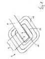
Die
Das Leitungsmittel
Das flächenhafte plattenförmige Trägermittel
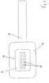
Vorzugsweise nach dem unterdruckdichten Fügen des Leitungsmittels
Das Leitungsmittel
Die Dickenerstreckung D des Verbunds aus Leitungsmittel
Das flachbauende und aus einem biegsamen Material, vorzugsweise auf Silikonbasis, und weiter vorzugsweise einstückig ausgebildete Leitungsmittel
ZITATE ENTHALTEN IN DER BESCHREIBUNG QUOTES INCLUDE IN THE DESCRIPTION
Diese Liste der vom Anmelder aufgeführten Dokumente wurde automatisiert erzeugt und ist ausschließlich zur besseren Information des Lesers aufgenommen. Die Liste ist nicht Bestandteil der deutschen Patent- bzw. Gebrauchsmusteranmeldung. Das DPMA übernimmt keinerlei Haftung für etwaige Fehler oder Auslassungen.This list of the documents listed by the applicant has been generated automatically and is included solely for the better information of the reader. The list is not part of the German patent or utility model application. The DPMA assumes no liability for any errors or omissions.
Zitierte PatentliteraturCited patent literature
- WO 2006/052338 A2[0002]WO 2006/052338 A2[0002]
Zitierte Nicht-PatentliteraturCited non-patent literature
- DIN 53505 vom August 2000[0004]DIN 53505 from August 2000[0004]
- DIN 53505 vom August 2000[0007]DIN 53505 from August 2000[0007]
Claims (18)
Translated fromGermanPriority Applications (10)
| Application Number | Priority Date | Filing Date | Title |
|---|---|---|---|
| DE102009060596ADE102009060596A1 (en) | 2009-12-23 | 2009-12-23 | Connection device for use in the vacuum treatment of wounds |
| RU2012130604/14ARU2555105C2 (en) | 2009-12-23 | 2010-12-07 | Connecting device applicable in negative-pressure wound healing |
| JP2012545128AJP5752146B2 (en) | 2009-12-23 | 2010-12-07 | Connecting device for use in negative pressure treatment of wounds |
| PCT/EP2010/007413WO2011076340A1 (en) | 2009-12-23 | 2010-12-07 | Connecting device for use in negative pressure wound therapy |
| ES10794872.1TES2459115T3 (en) | 2009-12-23 | 2010-12-07 | Connection device for use in the treatment of wounds with negative pressure |
| CN201080059066.8ACN102686263B (en) | 2009-12-23 | 2010-12-07 | Connecting device for use in vacuum therapy of trauma |
| BR112012015654-3ABR112012015654B1 (en) | 2009-12-23 | 2010-12-07 | COUPLER DEVICE FOR USE IN TREATING INJURY WITH SUBPRESSION |
| PL10794872TPL2515989T3 (en) | 2009-12-23 | 2010-12-07 | Connecting device for use in negative pressure wound therapy |
| EP10794872.1AEP2515989B1 (en) | 2009-12-23 | 2010-12-07 | Connecting device for use in negative pressure wound therapy |
| US12/974,067US8771244B2 (en) | 2009-12-23 | 2010-12-21 | Attachment device for use in the vacuum therapy of wounds |
Applications Claiming Priority (1)
| Application Number | Priority Date | Filing Date | Title |
|---|---|---|---|
| DE102009060596ADE102009060596A1 (en) | 2009-12-23 | 2009-12-23 | Connection device for use in the vacuum treatment of wounds |
Publications (1)
| Publication Number | Publication Date |
|---|---|
| DE102009060596A1true DE102009060596A1 (en) | 2011-06-30 |
Family
ID=43466564
Family Applications (1)
| Application Number | Title | Priority Date | Filing Date |
|---|---|---|---|
| DE102009060596AWithdrawnDE102009060596A1 (en) | 2009-12-23 | 2009-12-23 | Connection device for use in the vacuum treatment of wounds |
Country Status (10)
| Country | Link |
|---|---|
| US (1) | US8771244B2 (en) |
| EP (1) | EP2515989B1 (en) |
| JP (1) | JP5752146B2 (en) |
| CN (1) | CN102686263B (en) |
| BR (1) | BR112012015654B1 (en) |
| DE (1) | DE102009060596A1 (en) |
| ES (1) | ES2459115T3 (en) |
| PL (1) | PL2515989T3 (en) |
| RU (1) | RU2555105C2 (en) |
| WO (1) | WO2011076340A1 (en) |
Cited By (7)
| Publication number | Priority date | Publication date | Assignee | Title |
|---|---|---|---|---|
| WO2012069167A1 (en) | 2010-11-25 | 2012-05-31 | Paul Hartmann Ag | Wound dressing for negative pressure therapy |
| DE102011108726A1 (en) | 2011-07-26 | 2013-01-31 | Paul Hartmann Ag | Connection device for use in the vacuum treatment of wounds |
| WO2013034374A1 (en) | 2011-09-08 | 2013-03-14 | Paul Hartmann Ag | Connection device for use in negative pressure wound therapy |
| WO2014023500A1 (en) | 2012-08-09 | 2014-02-13 | Paul Hartmann Ag | Method for producing a connection device for use in negative pressure therapy for wounds |
| WO2014023501A1 (en) | 2012-08-09 | 2014-02-13 | Paul Hartmann Ag | Connection device for use in negative pressure therapy for wounds |
| WO2014023502A1 (en) | 2012-08-09 | 2014-02-13 | Paul Hartmann Ag | Flexible tube line for use in the negative pressure therapy of wounds |
| CN114340524A (en)* | 2019-07-24 | 2022-04-12 | 阿利迪亚保健公司 | Uterine bleeding control system and method |
Families Citing this family (52)
| Publication number | Priority date | Publication date | Assignee | Title |
|---|---|---|---|---|
| GB0723872D0 (en) | 2007-12-06 | 2008-01-16 | Smith & Nephew | Apparatus for topical negative pressure therapy |
| US9033942B2 (en) | 2008-03-07 | 2015-05-19 | Smith & Nephew, Inc. | Wound dressing port and associated wound dressing |
| AU2010341491B2 (en)* | 2009-12-22 | 2015-05-14 | Smith & Nephew, Inc. | Apparatuses and methods for negative pressure wound therapy |
| USRE48117E1 (en)* | 2010-05-07 | 2020-07-28 | Smith & Nephew, Inc. | Apparatuses and methods for negative pressure wound therapy |
| RU2016111981A (en) | 2010-12-22 | 2018-11-27 | Смит Энд Нефью, Инк. | DEVICE AND METHOD FOR TREATING RAS WITH NEGATIVE PRESSURE |
| USD714433S1 (en) | 2010-12-22 | 2014-09-30 | Smith & Nephew, Inc. | Suction adapter |
| US9421132B2 (en) | 2011-02-04 | 2016-08-23 | University Of Massachusetts | Negative pressure wound closure device |
| WO2012170744A2 (en)* | 2011-06-07 | 2012-12-13 | Spiracur, Inc. | Solutions for bridging and pressure concentration reduction at wound sites |
| AU2012284618B2 (en)* | 2011-07-19 | 2017-05-18 | Shieldheart Medtech Ab | Stabilizer, barrier disc and wound dressing comprising stabilizer, method for controlling the position of a wound dressing or barrier disc, and method for facilitating drainage from a wound dressing or barrier disc in negative pressure wound treatment |
| DE102011082347A1 (en)* | 2011-09-08 | 2013-03-14 | Paul Hartmann Ag | Wound dressing for use in the vacuum treatment of wounds |
| EP2567682B2 (en) | 2011-09-09 | 2017-12-27 | Paul Hartmann AG | Abdominal wound dressing with application aid |
| EP2567681B1 (en) | 2011-09-09 | 2014-11-12 | Paul Hartmann AG | Wound dressing for the abdominal area |
| EP2626049B1 (en) | 2012-02-11 | 2018-07-25 | Paul Hartmann AG | Wound treatment device |
| EP2852333B1 (en) | 2012-05-22 | 2021-12-15 | Smith & Nephew plc | Apparatuses for wound therapy |
| JP6400570B2 (en) | 2012-05-23 | 2018-10-10 | スミス アンド ネフュー ピーエルシーSmith & Nephew Public Limited Company | Apparatus and method for local negative pressure closure therapy |
| AU2013264937B2 (en) | 2012-05-24 | 2018-04-19 | Smith & Nephew Inc. | Devices and methods for treating and closing wounds with negative pressure |
| MX369689B (en) | 2012-07-16 | 2019-11-19 | Smith & Nephew Inc | Negative pressure wound closure device. |
| WO2014020440A1 (en) | 2012-08-01 | 2014-02-06 | Smith & Nephew Plc | Wound dressing |
| CN108186200B (en) | 2012-08-01 | 2021-08-10 | 史密夫及内修公开有限公司 | Wound dressing |
| DE102012214182A1 (en) | 2012-08-09 | 2014-03-06 | Paul Hartmann Ag | Connection device for use in the negative pressure therapy of wounds |
| EP2759310B2 (en) | 2013-01-28 | 2023-11-08 | Mölnlycke Health Care AB | Suction device |
| USD738487S1 (en) | 2013-01-28 | 2015-09-08 | Molnlycke Health Care Ab | Suction device for negative pressure therapy |
| DE102013002497A1 (en)* | 2013-02-13 | 2014-08-14 | Paul Hartmann Ag | Bandage kit for the treatment of wound cavities |
| DE102013002521A1 (en)* | 2013-02-13 | 2014-08-14 | Paul Hartmann Ag | Abdominal wound pad with lanyard |
| US10124098B2 (en) | 2013-03-13 | 2018-11-13 | Smith & Nephew, Inc. | Negative pressure wound closure device and systems and methods of use in treating wounds with negative pressure |
| TWI527600B (en)* | 2013-04-26 | 2016-04-01 | 科際器材工業股份有限公司 | Suction drainage member |
| US10010658B2 (en) | 2013-05-10 | 2018-07-03 | Smith & Nephew Plc | Fluidic connector for irrigation and aspiration of wounds |
| EP2837369B1 (en) | 2013-08-16 | 2018-06-13 | Paul Hartmann AG | Sealing element for a wound dressing for vacuum therapy |
| CN106170275B (en) | 2013-10-21 | 2021-05-07 | 史密夫和内修有限公司 | Negative pressure wound closure device |
| RU2555392C2 (en)* | 2013-10-23 | 2015-07-10 | Федеральное государственное бюджетное образовательное учреждение высшего профессионального образования Томский государственный университет систем управления и радиоэлектроники | Method of treating acute and chronic wounds |
| AU2015208299B2 (en) | 2014-01-21 | 2019-11-21 | Smith & Nephew Plc | Collapsible dressing for negative pressure wound treatment |
| DE102014106518A1 (en) | 2014-05-09 | 2015-11-12 | Paul Hartmann Ag | Foam wound dressing for negative pressure therapy |
| US10610414B2 (en)* | 2014-06-18 | 2020-04-07 | Smith & Nephew Plc | Wound dressing and method of treatment |
| DE102014116912A1 (en) | 2014-11-19 | 2016-05-19 | Paul Hartmann Ag | Fluid indicator for negative pressure device |
| DE102014116910A1 (en) | 2014-11-19 | 2016-05-19 | Paul Hartmann Ag | Electronic fluid sensor for negative pressure therapy device |
| AU2016254119A1 (en) | 2015-04-29 | 2017-10-05 | Smith & Nephew Inc. | Negative pressure wound closure device |
| US10076594B2 (en) | 2015-05-18 | 2018-09-18 | Smith & Nephew Plc | Fluidic connector for negative pressure wound therapy |
| DE102015110432A1 (en) | 2015-06-29 | 2016-12-29 | Paul Hartmann Ag | Instillation adapter for a vacuum wound treatment system |
| EP3124060B1 (en) | 2015-07-28 | 2019-09-11 | Paul Hartmann AG | Silencer for a vacuum therapy unit |
| EP3124059B1 (en) | 2015-07-28 | 2018-12-05 | Paul Hartmann AG | Silencer for a vacuum therapy unit |
| DE102015224746A1 (en)* | 2015-12-09 | 2017-06-14 | Paul Hartmann Ag | Connection device for use in the negative pressure therapy of wounds |
| US11471586B2 (en) | 2015-12-15 | 2022-10-18 | University Of Massachusetts | Negative pressure wound closure devices and methods |
| TWI615163B (en)* | 2016-01-12 | 2018-02-21 | 富強醫材股份有限公司 | Closed-wound drainage device |
| JP7231227B2 (en) | 2017-02-22 | 2023-03-01 | コーネル ユニヴァーシティー | Mechanical vacuum dressing for mechanical management, protection and aspiration of small incisions |
| AU201716716S (en) | 2017-05-11 | 2017-11-21 | MAƒA¶LNLYCKE HEALTH CARE AB | Wound dressings |
| GB201718014D0 (en) | 2017-11-01 | 2017-12-13 | Smith & Nephew | Dressing for negative pressure wound therapy with filter |
| CA3084180A1 (en) | 2017-12-06 | 2019-06-13 | Cornell University | Manually-operated negative pressure wound therapy (npwt) bandage with improved pump efficiency, automatic pressure indicator and automatic pressure limiter |
| GB201811449D0 (en) | 2018-07-12 | 2018-08-29 | Smith & Nephew | Apparatuses and methods for negative pressure wound therapy |
| GB202000574D0 (en) | 2020-01-15 | 2020-02-26 | Smith & Nephew | Fluidic connectors for negative pressure wound therapy |
| USD1043997S1 (en)* | 2020-09-18 | 2024-09-24 | Jake Timothy | Compression wound dressing |
| AU2024231034A1 (en)* | 2023-03-07 | 2025-09-18 | Convatec Limited | An airway for a negative pressure wound dressing |
| EP4574114A1 (en) | 2023-12-20 | 2025-06-25 | Paul Hartmann AG | Island dressing for wound treatment comprising an acrylate adhesive in the edge region and a silicone gel in the wound contact region |
Citations (5)
| Publication number | Priority date | Publication date | Assignee | Title |
|---|---|---|---|---|
| WO2006052338A2 (en) | 2004-11-08 | 2006-05-18 | Boehringer Laboratories, Inc. | Tube attachment device for wound treatment |
| DE102005015878A1 (en)* | 2005-04-06 | 2006-10-12 | Inmeditec Medizintechnik Gmbh | Hose connection for vacuum therapy device |
| DE102008020553A1 (en)* | 2007-04-29 | 2008-10-30 | Iskia Gmbh & Co.Kg | Flat drainage for wound treatment |
| DE202009005934U1 (en)* | 2009-04-22 | 2009-06-25 | Neubauer, Norbert | drainage device |
| DE202009016804U1 (en)* | 2009-12-12 | 2010-03-04 | Neubauer, Norbert | Labyrinth material for flat drainage for wound treatment |
Family Cites Families (18)
| Publication number | Priority date | Publication date | Assignee | Title |
|---|---|---|---|---|
| JPS61133050U (en)* | 1984-12-19 | 1986-08-19 | ||
| US5116310A (en)* | 1990-07-30 | 1992-05-26 | Helix Medical, Inc. | Multiple lumen wound drain with bypass openings |
| US7198046B1 (en)* | 1991-11-14 | 2007-04-03 | Wake Forest University Health Sciences | Wound treatment employing reduced pressure |
| NL1006457C2 (en)* | 1997-07-03 | 1999-01-05 | Polymedics N V | Drainage system to be used with an open wound, element used for applying a drainage pipe or hose and method for applying the drainage system. |
| EP1461113A4 (en)* | 2001-12-26 | 2009-05-06 | Hill Rom Services Inc | Wound vacuum therapy dressing kit |
| US8734404B2 (en)* | 2005-03-17 | 2014-05-27 | Patented Medical Solutions, Llc | Lay flat tubing |
| EP1986718B1 (en)* | 2006-02-06 | 2015-10-28 | KCI Licensing, Inc. | Systems for improved connection to wound dressings in conjunction with reduced pressure wound treatment systems |
| US20080097270A1 (en)* | 2006-08-25 | 2008-04-24 | Utterberg David S | Resilient hemostasis devices |
| BRPI0715320A2 (en)* | 2006-10-13 | 2013-07-09 | Kci Licensing Inc | manually activated reduced pressure treatment system, activating method of a reduced pressure treatment pump and low profile reduced pressure treatment system |
| US8083712B2 (en)* | 2007-03-20 | 2011-12-27 | Neogen Technologies, Inc. | Flat-hose assembly for wound drainage system |
| SE531259C2 (en)* | 2007-06-27 | 2009-02-03 | Moelnlycke Health Care Ab | Device for treating reduced pressure ulcers |
| EP2203137B1 (en)* | 2007-10-11 | 2016-02-24 | Spiracur, Inc. | Closed incision negative pressure wound therapy device |
| US9033942B2 (en)* | 2008-03-07 | 2015-05-19 | Smith & Nephew, Inc. | Wound dressing port and associated wound dressing |
| US8152785B2 (en)* | 2008-03-13 | 2012-04-10 | Tyco Healthcare Group Lp | Vacuum port for vacuum wound therapy |
| US20090281526A1 (en)* | 2008-05-09 | 2009-11-12 | Tyco Healthcare Group Lp | Negative Pressure Wound Therapy Apparatus Including a Fluid Line Coupling |
| CA2744548C (en)* | 2008-11-25 | 2017-06-13 | Spiracur Inc. | Device for delivery of reduced pressure to body surfaces |
| AU2010341491B2 (en)* | 2009-12-22 | 2015-05-14 | Smith & Nephew, Inc. | Apparatuses and methods for negative pressure wound therapy |
| DE102011082341A1 (en)* | 2011-09-08 | 2013-03-14 | Paul Hartmann Ag | Connection device for use in the vacuum treatment of wounds |
- 2009
- 2009-12-23DEDE102009060596Apatent/DE102009060596A1/ennot_activeWithdrawn
- 2010
- 2010-12-07RURU2012130604/14Apatent/RU2555105C2/enactive
- 2010-12-07EPEP10794872.1Apatent/EP2515989B1/enactiveActive
- 2010-12-07BRBR112012015654-3Apatent/BR112012015654B1/enactiveIP Right Grant
- 2010-12-07PLPL10794872Tpatent/PL2515989T3/enunknown
- 2010-12-07CNCN201080059066.8Apatent/CN102686263B/enactiveActive
- 2010-12-07JPJP2012545128Apatent/JP5752146B2/ennot_activeExpired - Fee Related
- 2010-12-07ESES10794872.1Tpatent/ES2459115T3/enactiveActive
- 2010-12-07WOPCT/EP2010/007413patent/WO2011076340A1/enactiveApplication Filing
- 2010-12-21USUS12/974,067patent/US8771244B2/enactiveActive
Patent Citations (5)
| Publication number | Priority date | Publication date | Assignee | Title |
|---|---|---|---|---|
| WO2006052338A2 (en) | 2004-11-08 | 2006-05-18 | Boehringer Laboratories, Inc. | Tube attachment device for wound treatment |
| DE102005015878A1 (en)* | 2005-04-06 | 2006-10-12 | Inmeditec Medizintechnik Gmbh | Hose connection for vacuum therapy device |
| DE102008020553A1 (en)* | 2007-04-29 | 2008-10-30 | Iskia Gmbh & Co.Kg | Flat drainage for wound treatment |
| DE202009005934U1 (en)* | 2009-04-22 | 2009-06-25 | Neubauer, Norbert | drainage device |
| DE202009016804U1 (en)* | 2009-12-12 | 2010-03-04 | Neubauer, Norbert | Labyrinth material for flat drainage for wound treatment |
Non-Patent Citations (1)
| Title |
|---|
| DIN 53505 vom August 2000 |
Cited By (14)
| Publication number | Priority date | Publication date | Assignee | Title |
|---|---|---|---|---|
| WO2012069167A1 (en) | 2010-11-25 | 2012-05-31 | Paul Hartmann Ag | Wound dressing for negative pressure therapy |
| DE102010052336A1 (en) | 2010-11-25 | 2012-05-31 | Paul Hartmann Ag | Wound dressing for the negative pressure therapy |
| DE102011108726A1 (en) | 2011-07-26 | 2013-01-31 | Paul Hartmann Ag | Connection device for use in the vacuum treatment of wounds |
| WO2013013938A1 (en) | 2011-07-26 | 2013-01-31 | Paul Hartmann Ag | Connector device for use in negative-pressure therapy of wounds |
| WO2013034374A1 (en) | 2011-09-08 | 2013-03-14 | Paul Hartmann Ag | Connection device for use in negative pressure wound therapy |
| DE102011082341A1 (en) | 2011-09-08 | 2013-03-14 | Paul Hartmann Ag | Connection device for use in the vacuum treatment of wounds |
| WO2014023500A1 (en) | 2012-08-09 | 2014-02-13 | Paul Hartmann Ag | Method for producing a connection device for use in negative pressure therapy for wounds |
| WO2014023501A1 (en) | 2012-08-09 | 2014-02-13 | Paul Hartmann Ag | Connection device for use in negative pressure therapy for wounds |
| WO2014023502A1 (en) | 2012-08-09 | 2014-02-13 | Paul Hartmann Ag | Flexible tube line for use in the negative pressure therapy of wounds |
| DE102012214180A1 (en) | 2012-08-09 | 2014-03-06 | Paul Hartmann Aktiengesellschaft | Conductive agents for use in negative pressure therapy of wounds |
| DE102012214178A1 (en) | 2012-08-09 | 2014-06-12 | Paul Hartmann Ag | Connection device for use in the negative pressure therapy of wounds |
| DE102012214175A1 (en) | 2012-08-09 | 2014-06-12 | Paul Hartmann Ag | A method of making a connector for use in wound wound therapy |
| US9586000B2 (en) | 2012-08-09 | 2017-03-07 | Paul Hartmann Ag | Connection device for use in the negative pressure treatment of wounds |
| CN114340524A (en)* | 2019-07-24 | 2022-04-12 | 阿利迪亚保健公司 | Uterine bleeding control system and method |
Also Published As
| Publication number | Publication date |
|---|---|
| CN102686263A (en) | 2012-09-19 |
| US20110152800A1 (en) | 2011-06-23 |
| RU2555105C2 (en) | 2015-07-10 |
| JP5752146B2 (en) | 2015-07-22 |
| RU2012130604A (en) | 2014-01-27 |
| BR112012015654A2 (en) | 2018-05-29 |
| WO2011076340A1 (en) | 2011-06-30 |
| EP2515989B1 (en) | 2014-02-19 |
| BR112012015654B1 (en) | 2020-02-11 |
| JP2013515518A (en) | 2013-05-09 |
| EP2515989A1 (en) | 2012-10-31 |
| CN102686263B (en) | 2015-09-30 |
| US8771244B2 (en) | 2014-07-08 |
| PL2515989T3 (en) | 2014-07-31 |
| ES2459115T3 (en) | 2014-05-08 |
Similar Documents
| Publication | Publication Date | Title |
|---|---|---|
| EP2515989B1 (en) | Connecting device for use in negative pressure wound therapy | |
| EP2528651B1 (en) | Connection device for use in negative-pressure wound therapy | |
| DE102010006272A1 (en) | connection device | |
| EP2753276B1 (en) | Connection device for use in negative pressure wound therapy | |
| WO2013013938A1 (en) | Connector device for use in negative-pressure therapy of wounds | |
| EP2636417B1 (en) | Wound treatment assembly and covering device for same | |
| DE60118546T2 (en) | ABDOMINALE WUNDAUFLAGE | |
| EP1888003B1 (en) | Dressing for the treatment of chronic wounds | |
| DE102010049895B4 (en) | Halpflaster for tracheal cannulas or artificial noses with speaking valve | |
| EP0782421B1 (en) | Device for sealing off an injury area | |
| DE60037824T2 (en) | WUNDABSAUGUNGSVORRICHTUNG WITH MULTI-PLUG CONNECTOR | |
| EP1874382A1 (en) | Tube connector for a vacuum therapy device | |
| WO2012041296A2 (en) | Device for wound treatment and wound covering plaster | |
| WO2008131896A1 (en) | Sealing body, especially for use in devices for vacuum-assisted wound treatment, and use thereof | |
| DE29715634U1 (en) | Device for connecting a drainage hose of an instillation vacuum seal | |
| DE102014227041A1 (en) | Connection device for use in the negative pressure therapy of wounds | |
| DE102014227042A1 (en) | Connection device for use in the negative pressure therapy of wounds | |
| DE202018005661U1 (en) | Sealing plaster for wounds | |
| DE3305610A1 (en) | Device for the localisation of a cannula | |
| AT15664U1 (en) | Wound care assembly, method of making and covering device therefor | |
| DE102011051657A1 (en) | Wound cover and device for suction of wound secretions | |
| DE202016102357U1 (en) | Hydrogel wound dressing | |
| DE102013008965A1 (en) | Device for protecting the environment of wounds | |
| DE102015108503A1 (en) | Device for the atraumatic treatment of wounds and a manufacturing method and a production device | |
| DE102013009737A1 (en) | Connection system for connecting a fluid line |
Legal Events
| Date | Code | Title | Description |
|---|---|---|---|
| R005 | Application deemed withdrawn due to failure to request examination |