DE102009060098A1 - Rail for immobilizing a body part and method for adapting a rail to a body part - Google Patents
Rail for immobilizing a body part and method for adapting a rail to a body partDownload PDFInfo
- Publication number
- DE102009060098A1 DE102009060098A1DE200910060098DE102009060098ADE102009060098A1DE 102009060098 A1DE102009060098 A1DE 102009060098A1DE 200910060098DE200910060098DE 200910060098DE 102009060098 ADE102009060098 ADE 102009060098ADE 102009060098 A1DE102009060098 A1DE 102009060098A1
- Authority
- DE
- Germany
- Prior art keywords
- body part
- plate
- longitudinal direction
- rail
- plastically deformable
- Prior art date
- Legal status (The legal status is an assumption and is not a legal conclusion. Google has not performed a legal analysis and makes no representation as to the accuracy of the status listed.)
- Withdrawn
Links
- 238000000034methodMethods0.000titleclaimsdescription7
- 230000003100immobilizing effectEffects0.000titledescription5
- 239000000463materialSubstances0.000claimsabstractdescription45
- 230000002787reinforcementEffects0.000claimsdescription11
- 210000003813thumbAnatomy0.000description12
- 239000004033plasticSubstances0.000description10
- 210000000707wristAnatomy0.000description8
- 230000006978adaptationEffects0.000description5
- 239000011505plasterSubstances0.000description5
- 230000006641stabilisationEffects0.000description5
- 238000011105stabilizationMethods0.000description5
- 210000000245forearmAnatomy0.000description4
- 229910052751metalInorganic materials0.000description4
- 239000002184metalSubstances0.000description4
- 210000003041ligamentAnatomy0.000description3
- 208000027418Wounds and injuryDiseases0.000description2
- 230000006378damageEffects0.000description2
- 229920001971elastomerPolymers0.000description2
- 239000004744fabricSubstances0.000description2
- 208000014674injuryDiseases0.000description2
- 239000000126substanceSubstances0.000description2
- 210000002435tendonAnatomy0.000description2
- 239000004753textileSubstances0.000description2
- 210000001519tissueAnatomy0.000description2
- BUHVIAUBTBOHAG-FOYDDCNASA-N(2r,3r,4s,5r)-2-[6-[[2-(3,5-dimethoxyphenyl)-2-(2-methylphenyl)ethyl]amino]purin-9-yl]-5-(hydroxymethyl)oxolane-3,4-diolChemical compoundCOC1=CC(OC)=CC(C(CNC=2C=3N=CN(C=3N=CN=2)[C@H]2[C@@H]([C@H](O)[C@@H](CO)O2)O)C=2C(=CC=CC=2)C)=C1BUHVIAUBTBOHAG-FOYDDCNASA-N0.000description1
- 229910000838Al alloyInorganic materials0.000description1
- 208000010392Bone FracturesDiseases0.000description1
- 0CC=NC*OCChemical compoundCC=NC*OC0.000description1
- 208000034656ContusionsDiseases0.000description1
- 206010061223Ligament injuryDiseases0.000description1
- 208000021945Tendon injuryDiseases0.000description1
- 230000001154acute effectEffects0.000description1
- 229910052782aluminiumInorganic materials0.000description1
- XAGFODPZIPBFFR-UHFFFAOYSA-NaluminiumChemical compound[Al]XAGFODPZIPBFFR-UHFFFAOYSA-N0.000description1
- 210000003423ankleAnatomy0.000description1
- 210000000544articulatio talocruralisAnatomy0.000description1
- 230000037237body shapeEffects0.000description1
- 210000000988bone and boneAnatomy0.000description1
- 239000011248coating agentSubstances0.000description1
- 238000000576coating methodMethods0.000description1
- 238000007796conventional methodMethods0.000description1
- 230000000694effectsEffects0.000description1
- 239000000806elastomerSubstances0.000description1
- 210000003414extremityAnatomy0.000description1
- 239000006260foamSubstances0.000description1
- 238000005187foamingMethods0.000description1
- 229910052602gypsumInorganic materials0.000description1
- 239000010440gypsumSubstances0.000description1
- 230000035876healingEffects0.000description1
- 230000001771impaired effectEffects0.000description1
- 210000004705lumbosacral regionAnatomy0.000description1
- 150000002739metalsChemical class0.000description1
- 238000004080punchingMethods0.000description1
- 230000000717retained effectEffects0.000description1
- 230000002441reversible effectEffects0.000description1
- 125000006850spacer groupChemical group0.000description1
- 230000008961swellingEffects0.000description1
- 230000001225therapeutic effectEffects0.000description1
- 239000012815thermoplastic materialSubstances0.000description1
- 238000009281ultraviolet germicidal irradiationMethods0.000description1
- 238000003466weldingMethods0.000description1
Images


Classifications
- A—HUMAN NECESSITIES
- A61—MEDICAL OR VETERINARY SCIENCE; HYGIENE
- A61F—FILTERS IMPLANTABLE INTO BLOOD VESSELS; PROSTHESES; DEVICES PROVIDING PATENCY TO, OR PREVENTING COLLAPSING OF, TUBULAR STRUCTURES OF THE BODY, e.g. STENTS; ORTHOPAEDIC, NURSING OR CONTRACEPTIVE DEVICES; FOMENTATION; TREATMENT OR PROTECTION OF EYES OR EARS; BANDAGES, DRESSINGS OR ABSORBENT PADS; FIRST-AID KITS
- A61F5/00—Orthopaedic methods or devices for non-surgical treatment of bones or joints; Nursing devices ; Anti-rape devices
- A61F5/01—Orthopaedic devices, e.g. long-term immobilising or pressure directing devices for treating broken or deformed bones such as splints, casts or braces
- A61F5/0102—Orthopaedic devices, e.g. long-term immobilising or pressure directing devices for treating broken or deformed bones such as splints, casts or braces specially adapted for correcting deformities of the limbs or for supporting them; Ortheses, e.g. with articulations
- A—HUMAN NECESSITIES
- A61—MEDICAL OR VETERINARY SCIENCE; HYGIENE
- A61F—FILTERS IMPLANTABLE INTO BLOOD VESSELS; PROSTHESES; DEVICES PROVIDING PATENCY TO, OR PREVENTING COLLAPSING OF, TUBULAR STRUCTURES OF THE BODY, e.g. STENTS; ORTHOPAEDIC, NURSING OR CONTRACEPTIVE DEVICES; FOMENTATION; TREATMENT OR PROTECTION OF EYES OR EARS; BANDAGES, DRESSINGS OR ABSORBENT PADS; FIRST-AID KITS
- A61F5/00—Orthopaedic methods or devices for non-surgical treatment of bones or joints; Nursing devices ; Anti-rape devices
- A61F5/01—Orthopaedic devices, e.g. long-term immobilising or pressure directing devices for treating broken or deformed bones such as splints, casts or braces
- A61F5/04—Devices for stretching or reducing fractured limbs; Devices for distractions; Splints
- A61F5/05—Devices for stretching or reducing fractured limbs; Devices for distractions; Splints for immobilising
- A61F5/058—Splints
- A61F5/05825—Strips of substantially planar form
Landscapes
- Health & Medical Sciences (AREA)
- Nursing (AREA)
- Orthopedic Medicine & Surgery (AREA)
- Engineering & Computer Science (AREA)
- Biomedical Technology (AREA)
- Heart & Thoracic Surgery (AREA)
- Vascular Medicine (AREA)
- Life Sciences & Earth Sciences (AREA)
- Animal Behavior & Ethology (AREA)
- General Health & Medical Sciences (AREA)
- Public Health (AREA)
- Veterinary Medicine (AREA)
- Orthopedics, Nursing, And Contraception (AREA)
Abstract
Translated fromGermanDescription
Translated fromGermanDie Erfindung betrifft eine Schiene zur Immobilisierung eines Körperteils.The invention relates to a rail for immobilizing a body part.
Die Erfindung betrifft ferner ein Verfahren zur Anpassung einer Schiene an ein Körperteil zu dessen Immobilisierung.The invention further relates to a method for adapting a splint to a body part for its immobilization.
Schienen zur Immobilisierung eines Körperteils werden zu therapeutischen Zwecken häufig verwendet, um ein Körperteil, insbesondere eine Extremität, ruhig zu stellen und eine Heilung einer Verletzung zu ermöglichen. Bei Knochenbrüchen dient die Schiene dazu, ein Verschieben der wieder zusammenwachsenden und vorher möglicherweise entsprechend gerichteten Knochenstücke zu verhindern. Bei Bänder- und Sehnenverletzungen dient die Ruhigstellung eines Gelenks dazu, einen Aufbau des Bänder- bzw. Sehnengewebes zu ermöglichen, ohne dass durch eine Belastung des entsprechenden Bandes oder der Sehne das noch nicht belastbare neue Gewebe wieder verletzt wird.Rails for immobilizing a body part are often used for therapeutic purposes, to immobilize a body part, in particular a limb, and to enable healing of an injury. In the case of bone fractures, the splint serves to prevent a movement of the rejoining and possibly possibly correspondingly directed bone pieces. In the case of ligament and tendon injuries, the immobilization of a joint serves to allow the tissue of the ligament or tendon to be built up, without any stress on the corresponding ligament or tendon causing the new tissue, which can not yet be stressed, to be injured again.
Die herkömmliche Methode des Anlegens einer Schiene besteht darin, mit nicht abgebundenem Gips versehene und in Wasser getränkte Bandagen um das Körperteil zu wickeln und trocknen zu lassen. Der Gips bindet dabei ab und härtet aus, sodass ein harter Gipsverband entsteht, der die Immobilisierung ermöglicht.The conventional method of applying a splint is to wrap and allow the non-set plaster and water-soaked bandages to wrap around the body part and allow to dry. The gypsum binds and hardens, resulting in a hard plaster cast that allows immobilization.
In ähnlicher Weise können mit einem UV-härtbarem Kunststoff versehene Bänder um das Körperteil gewickelt werden. Nach dem Anlegen des Verbandes wird der Kunststoff durch UV-Bestrahlung ausgehärtet, wodurch eine dem Gipsverband entsprechende Schiene entsteht. Anders als der Gipsverband ist die ausgehärtete Kunststoffschiene wasserfest.Similarly, tapes provided with a UV-curable plastic can be wrapped around the body part. After applying the dressing, the plastic is cured by UV irradiation, whereby a rail corresponding to the plaster cast arises. Unlike the plaster cast, the cured plastic rail is waterproof.
Durch
Alle bekannten Verfahren zur Anlegung einer das Körperteil immobilisierenden Schiene beruhen auf der Aushärtung eines flexibel an den Körper anzulegenden Materials, wodurch eine nicht reversible Anpassung an die Form des Körperteils entsteht, wenn das Material aushärtet. Fehler bei der Anpassung, die zu Druckstellen führen, können dabei kaum repariert werden und führen dazu, dass beispielsweise ein Gipsverband aufgeschnitten werden muss, wodurch seine eigentliche Funktion zumindest beeinträchtigt wird. Gleiches gilt für einen ausgehärteten Kunststoffverband, der nach dem Aushärten ebenfalls kaum noch korrigierbar ist. Aus diesem Grund erfordert das Anlegen des entsprechenden Schienenverbandes eine erhebliche Sorgfalt und eine große Erfahrung, damit das Auftreten von Druckstellen oder gar Fehlstellungen durch den ausgehärteten Verband vermieden werden.All known methods for applying a body part immobilizing rail are based on the curing of a flexible material to be applied to the body, whereby a non-reversible adaptation to the shape of the body part is formed when the material hardens. Mistakes in the adjustment, which lead to bruises, can hardly be repaired and cause, for example, a plaster cast must be cut, whereby its actual function is at least impaired. The same applies to a cured plastic dressing, which is also hardly correctable after curing. For this reason, the application of the corresponding splinting requires considerable care and a great deal of experience, so that the occurrence of pressure points or even misalignments are avoided by the cured bandage.
Eine Abmilderung des beschriebenen Problems ergibt sich daraus, dass die Aushärtung eines Kunststoffverbands mit Hilfe eines thermoplastischen Materials erfolgt, das somit durch Zufuhr von Wärme wieder plastisch verformbar gemacht werden kann, um einen Fehler bei einer vorhergehenden Aushärtung zu korrigiere.An alleviation of the described problem results from the fact that the curing of a plastic dressing takes place with the aid of a thermoplastic material, which can thus be made plastically deformable again by the application of heat in order to correct a mistake in a previous curing.
Der vorliegenden Erfindung liegt die Aufgabe zugrunde, die Anpassung einer Schiene an ein Körperteil zu dessen Immobilisierung zu erleichtern und die Nachteile der bekannten Schienen zu vermeiden.The present invention has for its object to facilitate the adaptation of a rail to a body part to its immobilization and to avoid the disadvantages of the known rails.
Zur Lösung dieser Aufgabe ist erfindungsgemäß ein Verfahren der eingangs erwähnten Art dadurch gekennzeichnet, dass eine mit einem Polstermaterial belegte Platte aus einem plastisch verformbaren Material in einer Längsrichtung an das Körperteil angelegt und quer zur Längsrichtung in seiner Form an das Körperteil angepasst wird und dass die so an das Körperteil angepasste Platte durch quer zur Längsrichtung wirkende Befestigungsmittel an dem Körperteil festgelegt und in seiner angepassten Form gehalten wird.To achieve this object, a method of the type mentioned above is characterized in that a covered with a cushioning material made of a plastically deformable material in a longitudinal direction to the body part and is adapted transversely to the longitudinal direction in its shape to the body part and that the so fixed to the body part plate is fixed by acting transversely to the longitudinal direction fastening means on the body part and held in its adapted form.
Die Aufgabe wird ferner dadurch gelöst, dass eine Schiene der eingangs erwähnten Art erfindungsgemäß gekennzeichnet ist durch eine mit einem Polstermaterial belegte Platte aus einem plastisch verformbaren Material, die in einer Längsrichtung an das Körperteil angelegt und quer zur Längsrichtung an das Körperteil angepasst verformt ist und dass die verformte Platte durch quer zur Längsrichtung wirksame Befestigungsmittel an dem Körperteil befestigbar und in dem verformten Zustand haltbar ist.The object is further achieved in that a rail of the type mentioned is characterized according to the invention by a covered with a cushioning material plate of a plastically deformable material which is applied in a longitudinal direction of the body part and deformed transversely to the longitudinal direction adapted to the body part and that the deformed plate can be fastened to the body part by means of fixing means which are effective transversely to the longitudinal direction and can be retained in the deformed state.
Die erfindungsgemäße Schiene ermöglicht eine Immobilisierung des Körperteils, ohne dass eine Aushärtung eines Stoffes erfolgen muss, durch den der in flexibler Form aufbringbare Stoff zu einem harten Material umgewandelt wird. Vielmehr wird erfindungsgemäß eine Platte aus einem plastisch verformbaren Material verwendet, das an sich für eine Immobilisierung des Körperteils gar nicht geeignet ist, weil die Platte plastisch verformbar ist. Die Erfindung beruht jedoch darauf, dass die Immobilisierung des Körperteils regelmäßig in einer Längsrichtung zu erfolgen hat, in der die Platte aus dem plastisch verformbaren Material dann nicht mehr durch normal auftretende Kräfte verformbar ist, wenn die Platte durch Anpassung an das Körperteil quer zur Längsrichtung verformt worden ist. Die plastisch verformbare Platte bildet dann in Längsrichtung eine Profilform aus, die den Verformungswiderstand in dieser Längsrichtung erheblich erhöht. Die Stabilisierung der Schiene quer zur Längsrichtung erfolgt durch quer zur Längsrichtung wirksame Befestigungsmittel, beispielsweise durch um das Körperteil schlingbare Befestigungsbändern, die quer zur Längsrichtung verlaufend angebracht werden, wobei „quer” einen rechten Winkel, aber auch davon abweichende spitze oder stumpfe Winkel einschließt. Die Haltefunktion der erfindungsgemäßen Schiene resultiert somit aus unterschiedlichen Effekten, nämlich durch die Verformung zu einem nicht mehr verformbaren Profil in Längsrichtung und die Stabilisierung der plastisch verformbaren Platte quer zur Längsrichtung, beispielsweise durch die um das Körperteil geschlungenen Befestigungsriemen. Als Befestigungsmittel kommen außer den, vorzugsweise durch Klettverschlüsse fixierbaren, Bändern als Befestigungsmittel an elastischen Gummibändern befestigte, sich in dem Polstermaterial verkrallende Haken, wie sie zur Festlegung von Bandagen bekannt sind, Haken und Ösen, Reißverschlüsse u. dgl. in Frage.The splint according to the invention makes it possible to immobilize the body part without having to harden a substance which converts the material which can be applied in flexible form into a hard material. Rather, a plate made of a plastically deformable material is used according to the invention, which is not suitable for immobilization of the body part, because the plate is plastically deformable. However, the invention is based on the fact that the immobilization of the body part regularly has to take place in a longitudinal direction, in which the plate of the plastically deformable material is then no longer deformable by normally occurring forces when the plate deformed by adaptation to the body part transversely to the longitudinal direction has been. The plastically deformable plate then forms a profile shape in the longitudinal direction, which considerably increases the deformation resistance in this longitudinal direction. The stabilization of the rail transversely to the longitudinal direction is effected by transversely to the longitudinal direction effective fastening means, for example, by the body part loopable fastening straps, which are mounted transversely to the longitudinal direction, wherein "transverse" includes a right angle, but also deviating acute or obtuse angle. The holding function of the rail according to the invention thus results from different effects, namely by the deformation to a no longer deformable profile in the longitudinal direction and the stabilization of the plastically deformable plate transverse to the longitudinal direction, for example by the looped around the body part attachment strap. As fasteners except the, preferably fixable by Velcro straps, fastened as fasteners to elastic rubber bands, in the cushioning material verkrallende hooks, as they are known for the definition of bandages, hooks and eyes, zippers u. Like. In question.
Die erfindungsgemäße Schiene bietet den Vorteil, dass sie leicht an die Form des Körperteils anpassbar ist, sodass sie leicht anlegbar ist. Die Stabilisierung mittels der Befestigungsmittel ist unproblematisch möglich und erfordert keine besonderen Fachkenntnisse. Darüber ist es unproblematisch möglich, eine falsch oder schlecht angelegte Schiene abzunehmen und neu anzulegen, da kein irrreversibel ausgehärtetes Material verwendet wird.The rail according to the invention has the advantage that it is easily adaptable to the shape of the body part, so that it is easy to apply. The stabilization by means of the fastening means is possible without problems and requires no special expertise. In addition, it is easy to remove a wrong or poorly applied rail and re-create because no irreversibly cured material is used.
In einer bevorzugten Ausführungsform der Erfindung sind die Befestigungsriemen mittels Klettverschlüssen an dem Polstermaterial festlegbar. Dadurch ist es sehr einfach möglich, einen weiteren Vorteil der erfindungsgemäßen Schiene auszunutzen, nämlich die Anpassung an das Körperteil zu verändern, wenn das Körperteil sich während der Tragezeit der Schiene verändert, beispielsweise eine durch die Verletzung entstandene Schwellung abgeschwollen ist.In a preferred embodiment of the invention, the fastening straps can be fixed to the padding material by means of hook-and-loop fasteners. This makes it very easy to exploit another advantage of the rail according to the invention, namely to change the adaptation to the body part when the body part changes during the wearing time of the rail, for example, a swelling resulting from the injury is swollen.
Es ist vorteilhaft, wenn für die erfindungsgemäße Schiene eine Platte verwendet wird, deren Kontur, nämlich ihre Außenkontur und/oder ihre Innenkontur, an das zur immobilisierende Körperteil angepasst ist.It is advantageous if, for the rail according to the invention, a plate is used whose contour, namely its outer contour and / or its inner contour, is adapted to the part of the body to be immobilized.
Als plastisch verformbares Material für die Platte kommen geeignete Metalle infrage. Insbesondere kann es vorteilhaft sein, die plastische Verformbarkeit dadurch auszubilden oder zumindest zu unterstützen, dass in das Material der Platte dicht an dicht liegende Durchgangsöffnungen eingebracht sind, sodass sich die Platte nur im Bereich der verbliebenen Stege zwischen den Durchgangsöffnungen verformen muss. Bei dieser Ausführungsform ist es möglich, eine Verstärkung in der Längsrichtung der Schiene dadurch auszubilden, dass in diesem Bereich keine Durchgangsöffnungen in das Material der Platte eingebracht sind, wodurch die Verformbarkeit des Materials in Längsrichtung bereits herabgesetzt wird. Das plastisch verformbare Material kann bevorzugt als Plattenmaterial oder als Rollenware vorliegen. Entsprechend dem Bedarf im Anwendungsfall kann die gewünschte Größe ab- bzw. ausgeschnitten werden.Suitable plastically deformable material for the plate are suitable metals. In particular, it may be advantageous to form the plastic deformability by or at least support that are introduced into the material of the plate close to tight passage openings, so that the plate must deform only in the region of the remaining webs between the through holes. In this embodiment, it is possible to form a reinforcement in the longitudinal direction of the rail in that in this area no through holes are made in the material of the plate, whereby the deformability of the material in the longitudinal direction is already reduced. The plastically deformable material may preferably be present as a plate material or as a rolled product. Depending on the need in the application, the desired size can be cut or cut.
Im Rahmen der Erfindung ist es aber auch möglich, das plastisch verformbare Material in der vorgesehenen Längsrichtung mit einer nachträglich eingebrachten Verstärkung zu versehen, die auf die Platte aufgelegt und in beliebiger Weise befestigt ist, beispielsweise mit dem Material der Platte verklebt oder verschweißt ist. Die Befestigung der Verstärkung kann alternativ auch an dem Polstermaterial erfolgen, insbesondere wenn auch die Verstärkung mit einem entsprechenden Polstermaterial überzogen ist, sodass die von Bandagen üblichen Befestigungsmittel, einschließlich von Klettverschlüssen, verwendbar sind.In the context of the invention, it is also possible to provide the plastically deformable material in the intended longitudinal direction with a subsequently introduced reinforcement, which is placed on the plate and fixed in any way, for example, glued or welded to the material of the plate. The attachment of the reinforcement can alternatively also take place on the padding material, in particular if the reinforcement is also covered with a corresponding padding material, so that the fastening means customary in bandages, including hook-and-loop fasteners, can be used.
Die Erfindung soll im Folgenden anhand von in der Zeichnung dargestellten Ausführungsbeispielen näher erläutert werden. Es zeigen:The invention will be explained in more detail below with reference to exemplary embodiments illustrated in the drawing. Show it:
Die Platte wird wenigstens auf einer Seite durch einen Polsterstoff als Polstermaterial
Bevorzugte Materialien für das Polstermaterial
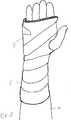
Zur Bildung einer erfindungsgemäßen Schiene, die beispielsweise gemäß
Bei dem in
Die
Grundsätzlich ist es auch denkbar, als zu umschließendes Körperteil den Rumpf des Patienten zu verwenden, wenn beispielsweise die Lendenwirbelsäule fixiert werden soll. In diesem Fall wird naturgemäß eine sehr große Platte
Es ist darauf hinzuweisen, dass die Bezeichnung „Längsrichtung” im vorliegenden Fall funktionell dem zu schienenden Körperteil
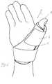
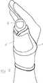
In
Bei der in
Aus den Darstellungen der
ZITATE ENTHALTEN IN DER BESCHREIBUNG QUOTES INCLUDE IN THE DESCRIPTION
Diese Liste der vom Anmelder aufgeführten Dokumente wurde automatisiert erzeugt und ist ausschließlich zur besseren Information des Lesers aufgenommen. Die Liste ist nicht Bestandteil der deutschen Patent- bzw. Gebrauchsmusteranmeldung. Das DPMA übernimmt keinerlei Haftung für etwaige Fehler oder Auslassungen.This list of the documents listed by the applicant has been generated automatically and is included solely for the better information of the reader. The list is not part of the German patent or utility model application. The DPMA assumes no liability for any errors or omissions.
Zitierte PatentliteraturCited patent literature
- WO 2008/092443 A1[0006]WO 2008/092443 A1[0006]
Claims (7)
Translated fromGermanPriority Applications (2)
| Application Number | Priority Date | Filing Date | Title |
|---|---|---|---|
| DE200910060098DE102009060098A1 (en) | 2009-12-21 | 2009-12-21 | Rail for immobilizing a body part and method for adapting a rail to a body part |
| PCT/DE2010/001402WO2011076164A1 (en) | 2009-12-21 | 2010-12-01 | Splint for immobilizing a body part and method for producing the splint |
Applications Claiming Priority (1)
| Application Number | Priority Date | Filing Date | Title |
|---|---|---|---|
| DE200910060098DE102009060098A1 (en) | 2009-12-21 | 2009-12-21 | Rail for immobilizing a body part and method for adapting a rail to a body part |
Publications (1)
| Publication Number | Publication Date |
|---|---|
| DE102009060098A1true DE102009060098A1 (en) | 2011-06-22 |
Family
ID=43798258
Family Applications (1)
| Application Number | Title | Priority Date | Filing Date |
|---|---|---|---|
| DE200910060098WithdrawnDE102009060098A1 (en) | 2009-12-21 | 2009-12-21 | Rail for immobilizing a body part and method for adapting a rail to a body part |
Country Status (2)
| Country | Link |
|---|---|
| DE (1) | DE102009060098A1 (en) |
| WO (1) | WO2011076164A1 (en) |
Cited By (2)
| Publication number | Priority date | Publication date | Assignee | Title |
|---|---|---|---|---|
| CN102551941A (en)* | 2012-02-27 | 2012-07-11 | 苏州奥芮济医疗科技有限公司 | Chest fracture fixation plate and bandage device and using method |
| CN112022479A (en)* | 2020-09-29 | 2020-12-04 | 成都市新都区中医医院 | Integrated fixing method for humerus surgical neck splint |
Families Citing this family (1)
| Publication number | Priority date | Publication date | Assignee | Title |
|---|---|---|---|---|
| RU177275U1 (en)* | 2017-07-17 | 2018-02-14 | Общество с ограниченной ответственностью "Фактор+" | Immobilization transport tire |
Citations (7)
| Publication number | Priority date | Publication date | Assignee | Title |
|---|---|---|---|---|
| US4161175A (en)* | 1977-04-29 | 1979-07-17 | Conco Medical Co., Inc. | Surgical finger and fence splints |
| US5409451A (en)* | 1993-06-16 | 1995-04-25 | Orthopedic Technology, Inc. | Wrist brace |
| US6039706A (en)* | 1995-12-20 | 2000-03-21 | Chrisofix Ag | Medical splint, metal sheet for such a splint and its use |
| US6290664B1 (en)* | 1998-10-23 | 2001-09-18 | Richard S. Nauert | User customizable knee brace |
| US20040225241A1 (en)* | 2003-02-03 | 2004-11-11 | Samuel Scheinberg | Orthopedic splints |
| DE202006013694U1 (en)* | 2006-08-29 | 2006-11-16 | Bort Gmbh | Wrist orthotic device for preventing ulna abduction and ulna deviation in the hand comprises a wing-like section arranged on a hand region for partially surrounding the hand on all sides |
| WO2008092443A1 (en) | 2007-01-31 | 2008-08-07 | Otto Bock Healthcare Gmbh | Method for producing an orthesis |
Family Cites Families (2)
| Publication number | Priority date | Publication date | Assignee | Title |
|---|---|---|---|---|
| DE3435955A1 (en)* | 1984-02-23 | 1985-09-26 | Gunter Dr. 6301 Wettenberg Grisar | JOINT CUFF |
| DE102007057578A1 (en)* | 2007-11-28 | 2009-06-10 | Otto Bock Healthcare Ip Gmbh & Co. Kg | Sprunggelenkorthesensystem |
- 2009
- 2009-12-21DEDE200910060098patent/DE102009060098A1/ennot_activeWithdrawn
- 2010
- 2010-12-01WOPCT/DE2010/001402patent/WO2011076164A1/enactiveApplication Filing
Patent Citations (7)
| Publication number | Priority date | Publication date | Assignee | Title |
|---|---|---|---|---|
| US4161175A (en)* | 1977-04-29 | 1979-07-17 | Conco Medical Co., Inc. | Surgical finger and fence splints |
| US5409451A (en)* | 1993-06-16 | 1995-04-25 | Orthopedic Technology, Inc. | Wrist brace |
| US6039706A (en)* | 1995-12-20 | 2000-03-21 | Chrisofix Ag | Medical splint, metal sheet for such a splint and its use |
| US6290664B1 (en)* | 1998-10-23 | 2001-09-18 | Richard S. Nauert | User customizable knee brace |
| US20040225241A1 (en)* | 2003-02-03 | 2004-11-11 | Samuel Scheinberg | Orthopedic splints |
| DE202006013694U1 (en)* | 2006-08-29 | 2006-11-16 | Bort Gmbh | Wrist orthotic device for preventing ulna abduction and ulna deviation in the hand comprises a wing-like section arranged on a hand region for partially surrounding the hand on all sides |
| WO2008092443A1 (en) | 2007-01-31 | 2008-08-07 | Otto Bock Healthcare Gmbh | Method for producing an orthesis |
Cited By (3)
| Publication number | Priority date | Publication date | Assignee | Title |
|---|---|---|---|---|
| CN102551941A (en)* | 2012-02-27 | 2012-07-11 | 苏州奥芮济医疗科技有限公司 | Chest fracture fixation plate and bandage device and using method |
| CN112022479A (en)* | 2020-09-29 | 2020-12-04 | 成都市新都区中医医院 | Integrated fixing method for humerus surgical neck splint |
| CN112022479B (en)* | 2020-09-29 | 2022-10-14 | 成都市新都区中医医院 | Integrated fixing method for humerus surgical neck splint |
Also Published As
| Publication number | Publication date |
|---|---|
| WO2011076164A1 (en) | 2011-06-30 |
Similar Documents
| Publication | Publication Date | Title |
|---|---|---|
| DE60015618T2 (en) | Universal carpal tunnel wrist splint assembly | |
| EP1904000B3 (en) | Bandage, especially as a supporting element of an orthosis | |
| EP2217183B1 (en) | Device for carrying out nail corrections | |
| DE102009036792A1 (en) | Compression bandage for mammals, especially for horses | |
| WO1998049979A1 (en) | Swivelling fracture orthosis | |
| DE3330813C2 (en) | Device for making nail corrections | |
| EP3897470A1 (en) | Elastic sheet material, bandage made thereof and method for producing said material | |
| EP2184040B1 (en) | Epicondylitis strap | |
| DE102009060098A1 (en) | Rail for immobilizing a body part and method for adapting a rail to a body part | |
| DE102009025416A1 (en) | Support or Fixiergurt | |
| EP2027834B1 (en) | Device for correcting nails | |
| DE102006010299A1 (en) | Nail e.g. big toe nail, correction clip, has retaining units in form of pads or foils, where continuously adjustable and definable force is exerted on units, and force transmits bending moment to body of nail by eccentric force engagement | |
| EP2480181B1 (en) | Fixing element and use of such an element for fixation of objects, in particular limbs | |
| EP4205707A1 (en) | Modifiable universal splint for wrist and finger stabilization, and modular kit for producing same | |
| CH709959A1 (en) | Wrist splint. | |
| EP2829255A1 (en) | Device for correcting nails | |
| DE202007017518U1 (en) | wrist support | |
| DE2500002C2 (en) | Curable device for fixing body parts | |
| DE102012111102A1 (en) | Assisting tool for stabilizing body parts e.g. limb of animal e.g. dog, has bond layer that is formed to stabilize, relief, immobilize and guide limb of animal at preset temperature to deform or modulate profile of animal parts | |
| DE202009010745U1 (en) | Compression bandage for mammals, especially for horses | |
| DE20302451U1 (en) | Orthosis with tether | |
| DE202023107556U1 (en) | Elastically deformable correction and/or stabilization strip, especially for treating a thumb saddle joint | |
| DE2133440C2 (en) | Knee joint support with limb contact portions - which are formed from plates shaped to match respective limb, both on same side of plane at right angles to pivot axis | |
| WO2012031707A1 (en) | Orthopaedic device and method for producing same | |
| DE19817628A1 (en) | Modular knee support orthosis for fast treatment of patients |
Legal Events
| Date | Code | Title | Description |
|---|---|---|---|
| R119 | Application deemed withdrawn, or ip right lapsed, due to non-payment of renewal fee | Effective date:20130702 |