DE102009057947A1 - Multifunctional touch and / or proximity sensor - Google Patents
Multifunctional touch and / or proximity sensorDownload PDFInfo
- Publication number
- DE102009057947A1 DE102009057947A1DE102009057947ADE102009057947ADE102009057947A1DE 102009057947 A1DE102009057947 A1DE 102009057947A1DE 102009057947 ADE102009057947 ADE 102009057947ADE 102009057947 ADE102009057947 ADE 102009057947ADE 102009057947 A1DE102009057947 A1DE 102009057947A1
- Authority
- DE
- Germany
- Prior art keywords
- electrode
- signal
- sensor
- sensor element
- field
- Prior art date
- Legal status (The legal status is an assumption and is not a legal conclusion. Google has not performed a legal analysis and makes no representation as to the accuracy of the status listed.)
- Withdrawn
Links
Images


Classifications
- H—ELECTRICITY
- H03—ELECTRONIC CIRCUITRY
- H03K—PULSE TECHNIQUE
- H03K17/00—Electronic switching or gating, i.e. not by contact-making and –breaking
- H03K17/94—Electronic switching or gating, i.e. not by contact-making and –breaking characterised by the way in which the control signals are generated
- H03K17/945—Proximity switches
- H03K17/955—Proximity switches using a capacitive detector
- G—PHYSICS
- G06—COMPUTING OR CALCULATING; COUNTING
- G06F—ELECTRIC DIGITAL DATA PROCESSING
- G06F1/00—Details not covered by groups G06F3/00 - G06F13/00 and G06F21/00
- G06F1/16—Constructional details or arrangements
- G06F1/1613—Constructional details or arrangements for portable computers
- G06F1/1626—Constructional details or arrangements for portable computers with a single-body enclosure integrating a flat display, e.g. Personal Digital Assistants [PDAs]
- G—PHYSICS
- G06—COMPUTING OR CALCULATING; COUNTING
- G06F—ELECTRIC DIGITAL DATA PROCESSING
- G06F1/00—Details not covered by groups G06F3/00 - G06F13/00 and G06F21/00
- G06F1/16—Constructional details or arrangements
- G06F1/1613—Constructional details or arrangements for portable computers
- G06F1/1633—Constructional details or arrangements of portable computers not specific to the type of enclosures covered by groups G06F1/1615 - G06F1/1626
- G06F1/1637—Details related to the display arrangement, including those related to the mounting of the display in the housing
- G06F1/1643—Details related to the display arrangement, including those related to the mounting of the display in the housing the display being associated to a digitizer, e.g. laptops that can be used as penpads
- H—ELECTRICITY
- H03—ELECTRONIC CIRCUITRY
- H03K—PULSE TECHNIQUE
- H03K17/00—Electronic switching or gating, i.e. not by contact-making and –breaking
- H03K17/94—Electronic switching or gating, i.e. not by contact-making and –breaking characterised by the way in which the control signals are generated
- H03K17/96—Touch switches
- H03K17/962—Capacitive touch switches
- H—ELECTRICITY
- H03—ELECTRONIC CIRCUITRY
- H03K—PULSE TECHNIQUE
- H03K2217/00—Indexing scheme related to electronic switching or gating, i.e. not by contact-making or -breaking covered by H03K17/00
- H03K2217/94—Indexing scheme related to electronic switching or gating, i.e. not by contact-making or -breaking covered by H03K17/00 characterised by the way in which the control signal is generated
- H03K2217/96—Touch switches
- H03K2217/9607—Capacitive touch switches
- H03K2217/960755—Constructional details of capacitive touch and proximity switches
- H03K2217/960765—Details of shielding arrangements
- H—ELECTRICITY
- H03—ELECTRONIC CIRCUITRY
- H03K—PULSE TECHNIQUE
- H03K2217/00—Indexing scheme related to electronic switching or gating, i.e. not by contact-making or -breaking covered by H03K17/00
- H03K2217/94—Indexing scheme related to electronic switching or gating, i.e. not by contact-making or -breaking covered by H03K17/00 characterised by the way in which the control signal is generated
- H03K2217/96—Touch switches
- H03K2217/9607—Capacitive touch switches
- H03K2217/960755—Constructional details of capacitive touch and proximity switches
- H03K2217/96077—Constructional details of capacitive touch and proximity switches comprising an electrode which is floating
- H—ELECTRICITY
- H03—ELECTRONIC CIRCUITRY
- H03K—PULSE TECHNIQUE
- H03K2217/00—Indexing scheme related to electronic switching or gating, i.e. not by contact-making or -breaking covered by H03K17/00
- H03K2217/94—Indexing scheme related to electronic switching or gating, i.e. not by contact-making or -breaking covered by H03K17/00 characterised by the way in which the control signal is generated
- H03K2217/96—Touch switches
- H03K2217/9607—Capacitive touch switches
- H03K2217/960755—Constructional details of capacitive touch and proximity switches
- H03K2217/960775—Emitter-receiver or "fringe" type detection, i.e. one or more field emitting electrodes and corresponding one or more receiving electrodes
Landscapes
- Engineering & Computer Science (AREA)
- Theoretical Computer Science (AREA)
- Computer Hardware Design (AREA)
- Human Computer Interaction (AREA)
- Physics & Mathematics (AREA)
- General Engineering & Computer Science (AREA)
- General Physics & Mathematics (AREA)
- Electronic Switches (AREA)
- Measurement Of Length, Angles, Or The Like Using Electric Or Magnetic Means (AREA)
- Switches That Are Operated By Magnetic Or Electric Fields (AREA)
- Geophysics And Detection Of Objects (AREA)
Abstract
Translated fromGerman
Description
Translated fromGermanGebiet der ErfindungField of the invention
Die Erfindung betrifft eine Sensoreinrichtung und ein Verfahren zum Bereitstellen eines Detektionssignals. Das Detektionssignal kann zum Steuern eines Geräteszustandes eines elektrischen Gerätes verwendet werden.The invention relates to a sensor device and a method for providing a detection signal. The detection signal can be used to control a device state of an electrical device.
Stand der TechnikState of the art
Im Stand der Technik sind Sensoreinrichtungen bekannt, welche etwa an einem Handgerät angeordnet werden können, um Messgrößen quantitativ zu erfassen. So ist es etwa bekannt, in einem Mobiltelefon im Bereich des Lautsprechers Infrarot-Sensoren vorzusehen, mit welchen der Abstand zu einem Objekte detektiert werden kann. So kann beispielsweise detektiert werden, wie weit das Mobiltelefon von einem Ohr entfernt ist. In Abhängigkeit von der Entfernung kann dann das Display des Mobiltelefons eingeschaltet oder ausgeschaltet werden.In the prior art sensor devices are known, which can be arranged on a hand-held device, for example, in order to quantitatively detect measured variables. For example, it is known to provide infrared sensors in a mobile telephone in the area of the loudspeaker with which the distance to an object can be detected. For example, it can be detected how far away the mobile phone is from an ear. Depending on the distance then the display of the mobile phone can be turned on or off.
Nachteilig ist hierbei, dass Infrarot-Sensoren von außen sichtbar sind, da zumindest der Messfühler an der Gehäuseoberfläche des Mobiltelefons angeordnet werden muss. Dies beschränkt zudem die Möglichkeiten der Gestaltung des Mobiltelefon-Gehäuses. Zudem kann nicht zuverlässig detektiert werden, ob sich das Mobiltelefon tatsächlich am Ohr befindet oder ob der Infrarot-Sensor bzw. der Messfühler nicht von z. B. einer Hand abgedeckt wird.The disadvantage here is that infrared sensors are visible from the outside, since at least the sensor must be arranged on the housing surface of the mobile phone. This also limits the possibilities of designing the mobile phone housing. In addition, it can not reliably be detected whether the mobile phone is actually at the ear or whether the infrared sensor or the sensor is not of z. B. a hand is covered.
Aufgabe der ErfindungObject of the invention
Der Erfindung liegt daher die Aufgabe zugrunde, eine Sensoreinrichtung bereitzustellen, welche die aus dem Stand der Technik bekannten Nachteile zumindest teilweise vermeidet.The invention is therefore based on the object to provide a sensor device which at least partially avoids the disadvantages known from the prior art.
Erfindungsgemäße LösungInventive solution
Diese Aufgabe wird erfindungsgemäß durch eine Sensoreinrichtung sowie durch ein Verfahren zum Bereitstellen eines Detektionssignals nach den unabhängigen Ansprüchen gelöst. Vorteilhafte Ausgestaltungen und Weiterbildungen der Erfindung sind in den abhängigen Ansprüchen angegeben.This object is achieved by a sensor device and by a method for providing a detection signal according to the independent claims. Advantageous embodiments and further developments of the invention are specified in the dependent claims.
Bereitgestellt wird demnach eine Sensoreinrichtung, welche umfasst:
- – zumindest ein erstes Sensorelement zur Berührungs- und/oder Annäherungsdetektion, welches als kapazitives Sensorelement ausgestaltet ist und welches eine erste Elektrodenstruktur, aufweisend eine Sendeelektrode und eine Empfangselektrode, umfasst, wobei ein von der Sendeelektrode emittiertes erstes elektrisches Wechselfeld in die Empfangselektrode einkoppelbar ist,
- – zumindest ein zweites Sensorelement, und
- – eine Auswerteeinrichtung, welche mit dem zumindest einen ersten Sensorelement und mit dem zumindest einen zweiten Sensorelement gekoppelt ist, wobei die Auswerteeinrichtung ausgestaltet ist, ein an der Empfangselektrode des ersten Sensorelements abgegriffenes erstes Signal und zumindest ein von dem zweiten Sensorelement bereitgestelltes zweites Signal auszuwerten und zumindest ein von der Auswertung abhängiges Detektionssignal zu erzeugen.
- At least a first sensor element for contact and / or proximity detection, which is designed as a capacitive sensor element and which comprises a first electrode structure, comprising a transmitting electrode and a receiving electrode, wherein a first alternating electric field emitted by the transmitting electrode can be coupled into the receiving electrode,
- - At least a second sensor element, and
- An evaluation device, which is coupled to the at least one first sensor element and to the at least one second sensor element, wherein the evaluation device is designed to evaluate a first signal picked up at the receiving electrode of the first sensor element and at least one second signal provided by the second sensor element to generate a detection signal dependent on the evaluation.
Damit kann z. B. ein Gerätezustand eines elektrischen Gerätes geändert werden, welcher nicht nur abhängig von der Berührung des Gerätes und/oder von der Annäherung an das Gerät ist, sondern auch abhängig von anderen Sensorwerten.This can z. B. a device state of an electrical device to be changed, which is not only dependent on the touch of the device and / or the approach to the device, but also dependent on other sensor values.
Vorteilhafterweise kann die Ergonomie, insbesondere von elektronischen Handgeräten, deutlich verbessert werden.Advantageously, the ergonomics, especially of electronic hand-held devices, can be significantly improved.
Die erste Elektrodenstruktur kann eine Kompensationselektrode aufweisen, welche im Wesentlichen zwischen der Sendeelektrode und der Empfangselektrode angeordnet ist, wobei die Auswerteeinrichtung eine Signalgebereinrichtung aufweist, zum Beaufschlagen der Sendeelektrode mit einem ersten elektrischen Wechselsignal und zum Beaufschlagen der Kompensationselektrode mit einem zweiten elektrischen Wechselsignal, wobei das zweite elektrische Wechselsignal phasenverschoben zu dem ersten elektrischen Wechselsignal ist, und wobei ein von der Kompensationselektrode emittiertes zweites elektrisches Wechselfeld in die Empfangselektrode einkoppelbar ist.The first electrode structure may comprise a compensation electrode, which is arranged substantially between the transmitting electrode and the receiving electrode, wherein the evaluation device comprises a signaling device for applying a first alternating electrical signal to the transmitting electrode and for applying a second alternating electrical signal to the compensating electrode, wherein the second electrical alternating signal is out of phase with the first electrical alternating signal, and wherein a second alternating electric field emitted by the compensation electrode can be coupled into the receiving electrode.
Damit kann bei entsprechender Anordnung der Sendeelektrode, der Empfangselektrode und der Kompensationselektrode an einem Handgerät besonders vorteilhaft die Detektion eines Umgreifens des Handgerätes durch eine Hand realisiert werden.This can be realized with a suitable arrangement of the transmitting electrode, the receiving electrode and the compensation electrode on a handset particularly advantageous detection of gripping the handset by a hand.
Das erste Sensorelement kann eine zweite Elektrodenstruktur, aufweisend eine Anzahl von Feldmesselektroden, umfassen, wobei die Empfangselektrode, die Sendeelektrode, die Kompensationselektrode und die Feldmesselektroden so relativ zueinander angeordnet sind, dass
- – das von Sendeelektrode emittierte erste elektrische Wechselfeld auch in zumindest eine der Feldmesselektroden einkoppelbar ist, und
- – das von der Kompensationselektrode emittierte zweite elektrische Wechselfeld im Wesentlichen nur in die Empfangselektrode einkoppelbar ist,
- - The first alternating electric field emitted by the transmitting electrode can also be coupled into at least one of the field sensing electrodes, and
- The second alternating electric field emitted by the compensation electrode can be coupled essentially only into the receiving electrode,
Mit den Feldmesselektroden kann der Observationsbereich des kapazitiven Sensorelementes an einem Handgeräte deutlich vergrößert werden, wobei gleichzeitig auch sicher gestellt wird, dass eine Annäherung nur an die Feldmesselektroden nicht zu einer Detektion führt, weil eine Detektion einer Annäherung an die Feldmesselektroden nur dann erreicht wird, wenn das an der Sendeelektrode emittierte Wechselfeld über die Hand in die Feldmesselektroden einkoppelt, was einer vergrößerten kapazitiven Koppelung zwischen Sendeelektrode und Feldmesselektroden entspricht. With the field sensing electrodes, the observation range of the capacitive sensor element can be significantly increased on a handset, while also ensuring that an approximation only to the field sensing leads to a detection, because detection of an approach to the field sensing is achieved only if the alternating field emitted at the transmitting electrode is coupled via the hand into the field measuring electrodes, which corresponds to an increased capacitive coupling between transmitting electrode and field measuring electrodes.
Die Amplitude des ersten elektrischen Wechselsignals kann größer sein als die Amplitude des zweiten elektrischen Wechselsignals.The amplitude of the first electrical alternating signal may be greater than the amplitude of the second electrical alternating signal.
Eine Annäherung eines Objektes an die erste Elektrodenstruktur kann zu einer Veränderung eines Pegels des an der Empfangselektrode abgegriffen ersten Signals führen, welche indikativ für eine Annäherung eines Objektes an die erste Elektrodenstruktur ist.An approach of an object to the first electrode structure can lead to a change in a level of the first signal picked up at the receiving electrode, which is indicative of an approach of an object to the first electrode structure.
Eine zusätzliche Annäherung des Objektes an die zweite Elektrodenstruktur kann zu einer Veränderung eines Pegels des zumindest eines an den Feldmesselektroden abgegriffen dritten Signals führen, wobei die Pegeländerung des dritten Signals indikativ dafür ist, dass sich das Objekt sowohl an die erste Elektrodenstruktur also auch an die zweite Elektrodenstruktur annähert.An additional approach of the object to the second electrode structure can lead to a change in a level of the at least one third signal tapped at the field measuring electrodes, wherein the level change of the third signal is indicative that the object is adjacent both to the first electrode structure and to the second Approximates electrode structure.
Zumindest einer der Feldmesselektroden kann eine Hilfselektrode zugeordnet sein, wobei die Hilfselektrode galvanisch oder kapazitiv mit der zumindest einen Feldmesselektroden koppelbar ist.At least one of the field sensing electrodes may be associated with an auxiliary electrode, wherein the auxiliary electrode is galvanically or capacitively coupled to the at least one field sensing electrode.
Das zweite Sensorelement kann zumindest eines aus Lagesensor, Beschleunigungssensor, Lichtsensor, und Temperatursensor, umfassen.The second sensor element may comprise at least one of a position sensor, an acceleration sensor, a light sensor, and a temperature sensor.
Durch die Erfindung bereitgestellt wird auch ein Verfahren zum Bereitstellen eines Detektionssignals, wobei
- – ein ersten Signal an einer Empfangselektrode eines ersten Sensorelements abgegriffen wird, wobei das erste Sensorelement als kapazitives Sensorelement ausgestaltet ist und eine erste Elektrodenstruktur, aufweisend eine Sendeelektrode und die Empfangselektrode, umfasst, wobei ein von der Sendeelektrode emittiertes erstes elektrisches Wechselfeld in die Empfangselektrode eingekoppelt wird,
- – das erste Signal ausgewertet wird,
- – ein zweites Signal ausgewertet wird, welches von einem zweiten Sensorelement bereitgestellt wird, und
- – ein Detektionssignal erzeugt wird, welches von dem ausgewerteten ersten Signal und von dem ausgewerteten zweiten Signal abhängig ist.
- - A first signal is tapped at a receiving electrode of a first sensor element, wherein the first sensor element is configured as a capacitive sensor element and a first electrode structure, comprising a transmitting electrode and the receiving electrode, wherein a first alternating electric field emitted by the transmitting electrode is coupled into the receiving electrode .
- - the first signal is evaluated,
- - A second signal is evaluated, which is provided by a second sensor element, and
- - A detection signal is generated, which is dependent on the evaluated first signal and the evaluated second signal.
Das erste Sensorelement kann eine zweite Elektrodenstruktur, aufweisend eine Anzahl von Feldmesselektroden, umfassen, wobei
- – das von der Sendeelektrode emittierte erste elektrische Wechselfeld in zumindest eine Feldmesselektroden eingekoppelt wird,
- – an zumindest einer Feldmesselektroden ein drittes Signal abgegriffen wird, und
- – das dritte Signal ausgewertet wird,
- The first alternating electric field emitted by the transmitting electrode is coupled into at least one field measuring electrode,
- - At least one Feldmesselektroden a third signal is tapped, and
- - the third signal is evaluated,
Die erste Elektrodenstruktur weist eine Kompensationselektrode auf, wobei die Sendeelektrode mit einem ersten elektrischen Wechselsignal und die Kompensationselektrode mit einem zweiten elektrischen Wechselsignal beaufschlagt werden, wobei das zweite elektrische Wechselsignal vorzugsweise phasenverschoben zu dem ersten elektrischen Wechselsignal ist.The first electrode structure has a compensation electrode, wherein the transmitting electrode is supplied with a first alternating electrical signal and the compensation electrode with a second alternating electrical signal, wherein the second alternating electrical signal is preferably out of phase with the first alternating electrical signal.
Die Empfangselektrode, die Sendeelektrode, die Kompensationselektrode und die Feldmesselektroden werden so relativ zueinander angeordnet, dass ein von der Kompensationselektrode emittiertes zweites elektrisches Wechselfeld im Wesentlichen nur in die Empfangselektrode eingekoppelt wird.The receiving electrode, the transmitting electrode, the compensation electrode and the Feldmesselektroden are arranged relative to each other, that a second alternating electric field emitted by the compensation electrode is coupled substantially only in the receiving electrode.
Bereitgestellt wird auch ein Verfahren zum Steuern eines Gerätezustandes eines elektrischen Gerätes, wobei aus einem Detektionssignal, welches von dem Verfahren zum Bereitstellen eines Detektionssignals bereitgestellt wird, Steuerinformationen abgeleitet werden, welche zur Steuerung des Gerätezustandes herangezogen werden.Also provided is a method for controlling a device state of an electrical device, wherein control information derived from a detection signal provided by the method for providing a detection signal is derived, which is used to control the device state.
Die Steuerinformationen können z. B. umfassen:
- – die räumliche Lage des Gerätes,
- – die Lichtverhältnisse in der Umgebung des Gerätes, oder
- – die Temperatur in der Umgebung des Gerätes oder die Temperatur im Geräteinneren.
- - the spatial position of the device,
- - the lighting conditions in the environment of the device, or
- - the temperature in the environment of the device or the temperature inside the device.
Kurzbeschreibung der FigurenBrief description of the figures
Weitere Einzelheiten und Merkmale der Erfindung sowie konkrete Ausführungsbeispiele der Erfindung ergeben sich aus der nachfolgenden Beschreibung in Verbindung mit der Zeichnung. Es zeigt:Further details and features of the invention and specific embodiments of the invention will become apparent from the following description taken in conjunction with the drawings. It shows:
Detaillierte Beschreibung der ErfindungDetailed description of the invention
Zunächst wird die Funktionsweise des kapazitiven Sensorelementes gemäß der Erfindung näher erläutert.First, the operation of the capacitive sensor element will be explained according to the invention.
Die erste Elektrodenstruktur weist eine Sendeelektrode SE, eine Kompensationselektrode KE und eine Empfangselektrode EE auf. Die Kompensationselektrode KE ist bei der in
Die zweite Elektrodenstruktur weist hier vier Feldmesselektroden FE auf. Die Feldmesselektroden FE sind so relativ zur ersten Elektrodenstruktur angeordnet, dass ein von der Kompensationselektrode KE emittiertes elektrisches Wechselfeld WK im Wesentlichen nur in der Empfangselektrode EE einkoppelt, nicht aber in die Feldmesselektroden FE.The second electrode structure here has four field sensing electrodes FE. The field measuring electrodes FE are arranged relative to the first electrode structure in such a way that an alternating electric field WK emitted by the compensation electrode KE couples in substantially only in the receiving electrode EE, but not in the field measuring electrodes FE.
Die Empfangselektrode EE der ersten Elektrodenstruktur wird an einem Signaleingang einer Auswerteeinrichtung bzw. einer Steuerungseinrichtung angeschlossen. Die Sendeelektrode SE und die Kompensationselektrode KE der ersten Elektrodenstruktur werden jeweils mit einer elektrischen Wechselgröße einer bestimmten Frequenz und Amplitude beaufschlagt. Diese elektrische Wechselgröße wird im Folgenden als Wechselsignal oder elektrisches Wechselsignal bezeichnet.The receiving electrode EE of the first electrode structure is connected to a signal input of an evaluation device or a control device. The transmitting electrode SE and the compensation electrode KE of the first electrode structure are each subjected to an electrical alternating quantity of a specific frequency and amplitude. This electrical variable is referred to below as the alternating signal or electrical alternating signal.
Das an der Sendelektrode SE beaufschlagte elektrische Wechselsignal weist eine Frequenz von etwa zwischen 50 kHz und 300 kHz auf. Bevorzugt weist das an der Sendeelektrode SE beaufschlagte elektrische Wechselsignal eine Frequenz zwischen 75 kHz und 150 kHz auf.The electrical alternating signal applied to the transmitting electrode SE has a frequency of approximately between 50 kHz and 300 kHz. The electrical alternating signal applied to the transmitting electrode SE preferably has a frequency between 75 kHz and 150 kHz.
Das an der Kompensationselektrode KE beaufschlagte elektrische Wechselsignal weist vorzugsweise die Wellenform und die Frequenz des elektrischen Wechselsignals auf, mit welchem die Sendeelektrode SE beaufschlagt wird. Das elektrische Wechselsignal, mit welchem die Kompensationselektrode KE beaufschlagt wird, ist gegenüber dem elektrischen Wechselsignal der Sendeelektrode SE phasenverschoben. Die Phasenverschiebung kann etwa mit einem Phasenschieber bewerkstelligt werden, welcher zwischen einem Signalgenerator und der Sendeelektrode oder der Kompensationselektrode angeordnet ist (vgl.
Die Sendeelektrode SE bzw. das an ihr beaufschlagte elektrische Wechselsignal ist so ausgelegt, dass das von der Sendeelektrode SE emittierte elektrische Wechselfeld WS in die Empfangselektrode EE einkoppelbar ist. Die Kompensationselektrode KE bzw. das an ihr beaufschlagte elektrische Wechselsignal ist so ausgelegt, dass das an der Kompensationselektrode KE emittierte elektrische Wechselfeld WK ebenfalls in die Empfangselektrode EE einkoppelbar ist. Durch das an der Kompensationselektrode KE emittierte elektrische Wechselfeld WK, welches phasenverschoben zu dem von der Sendelektrode SE emittierten elektrischen Wechselfeld WS ist, wird der Pegel des an der Empfangselektrode EE einwirkenden elektrischen Wechselfeldes, welches aus den elektrischen Wechselfeldern WS und WK resultiert, reduziert bzw. bei einer gegenphasigen Überlagerung, d. h. bei einer Phasenverschiebung von 180° (nahezu) ausgelöscht.The transmitting electrode SE or the electrical alternating signal applied to it is designed so that the alternating electric field WS emitted by the transmitting electrode SE can be coupled into the receiving electrode EE. The compensation electrode KE or the electrical alternating signal applied to it is designed so that the alternating electric field WK emitted at the compensation electrode KE can likewise be coupled into the receiving electrode EE. Due to the alternating electric field WK emitted at the compensation electrode KE, which is phase-shifted relative to the alternating electric field WS emitted by the transmitting electrode SE, the level of the alternating electric field acting on the receiving electrode EE resulting from the alternating electric fields WS and WK is reduced or in an antiphase superposition, d. H. at a phase shift of 180 ° (almost) extinguished.
Die an der Empfangselektrode EE eingekoppelten elektrischen Wechselfelder WK und WS bewirken, dass in der Empfangselektrode EE ein Strom fließt, welcher von einer Auswerteelektronik überwacht bzw. ausgewertet werden kann. Dieser Strom ist indikativ für eine Annäherung, etwa einer Hand, an die erste Elektrodenstruktur bzw. für ein Berühren der ersten Elektrodenstruktur durch eine Hand. Beim Fehlen einer Hand, d. h. wenn sich keine Hand der ersten Elektrodenstruktur annähert bzw. wenn die erste Elektrodenstruktur nicht von einer Hand berührt wird, weist der in der Empfangselektrode EE fließende Strom einen Pegel auf, welcher unterhalb eines vorbestimmten Schaltpegels liegt. Erst bei einer ausreichenden Annäherung eines Objektes, etwa einer Hand, an die erste Elektrodenstruktur übersteigt der in der Empfangselektrode EE fließende Strom den vorbestimmten Schaltpegel, so dass eine Annäherung an die erste Elektrodenstruktur detektiert wird. The coupled to the receiving electrode EE alternating electric fields WK and WS cause that in the receiving electrode EE a current flows, which can be monitored or evaluated by an evaluation. This current is indicative of an approach, such as a hand, to the first electrode structure or for touching the first electrode structure by a hand. In the absence of a hand, that is, when no hand approaches the first electrode structure or when the first electrode structure is not touched by a hand, the current flowing in the receiving electrode EE has a level which is below a predetermined switching level. Only when the object, for example a hand, approaches the first electrode structure sufficiently, does the current flowing in the receiving electrode EE exceed the predetermined switching level, so that an approach to the first electrode structure is detected.
Die Sendeelektrode SE, die Kompensationselektrode KE und die Empfangselektrode EE der ersten Elektrodenstruktur können an einem Handgerät so angeordnet werden, dass anstelle einer Annäherung an die erste Elektrodenstruktur ein Berühren der ersten Elektrodenstruktur detektiert wird. Eine solche Elektrodenanordnung an einem Handgerät wird mit Bezug auf
Wie bereits erläutert, sind die Feldmesselektroden FE der zweiten Elektrodenstruktur so relativ zu der ersten Elektrodenstruktur angeordnet, dass das von der Kompensationselektrode KE der ersten Elektrodenstruktur emittierte elektrische Wechselfeld WK nicht in die Feldmesselektroden FE der zweiten Elektrodenstruktur einkoppelt. Um dies sicherzustellen, kann auch das an der Kompensationselektrode KE beaufschlagte elektrische Wechselsignal so eingestellt werden, dass das an der Kompensationselektrode KE emittierte elektrische Wechselfeld WK ausreichend klein ist, damit es nicht in die Feldmesselektroden FE der zweiten Elektrodenstruktur einkoppelt.As already explained, the field sensing electrodes FE of the second electrode structure are arranged relative to the first electrode structure such that the alternating electric field WK emitted by the compensation electrode KE of the first electrode structure does not couple into the field sensing electrodes FE of the second electrode structure. To ensure this, the alternating electrical signal applied to the compensation electrode KE can also be adjusted so that the alternating electric field WK emitted at the compensation electrode KE is sufficiently small that it does not couple into the field sensing electrodes FE of the second electrode structure.
In einem Anwendungsbeispiel der erfindungsgemäßen Sensoreinrichtung können die Feldmesselektroden FE der zweiten Elektrodenstruktur dazu vorgesehen sein, um gleichzeitig bei einer über die erste Elektrodenstruktur detektierte Berührung der ersten Elektrodenstruktur auch eine Annäherung bzw. ein Berühren der zweiten Elektrodenstruktur zu detektieren. Für diesen Zweck ist es ausreichend, wenn die Feldmesselektroden FE eine kleinere Fläche als die Empfangselektrode EE der ersten Elektrodenstruktur aufweist.In an exemplary application of the sensor device according to the invention, the field sensing electrodes FE of the second electrode structure may be provided for simultaneously detecting an approach or touching of the second electrode structure in the case of a contact of the first electrode structure detected via the first electrode structure. For this purpose, it is sufficient if the field sensing electrode FE has a smaller area than the receiving electrode EE of the first electrode structure.
Das an der Sendeelektrode SE der ersten Elektrodenstruktur emittierte elektrische Wechselfeld WS kann in die Feldmesselektroden FE der zweiten Elektrodenstruktur einkoppeln. Beim Fehlen einer Hand in dem Observationsbereich zwischen der ersten Elektrodenstruktur und der zweiten Elektrodenstruktur ist diese kapazitive Koppelung allerdings sehr gering bzw. vernachlässigbar klein. Das an den Feldmesselektroden FE eingekoppelte elektrische Wechselfeld WS bewirkt, dass in den Feldmesselektroden FE ein elektrischer Strom fließt, welcher mit einer Auswerteeinrichtung detektiert bzw. ausgewertet werden kann. Für diesen in den Feldmesselektroden FE fließenden elektrischen Strom kann ebenfalls ein Signalpegel definiert werden, wobei ein Überschreiten dieses Signalpegels indikativ für eine Annäherung eines Objektes an die Feldmesselektroden FE ist.The alternating electric field WS emitted at the transmitting electrode SE of the first electrode structure can be coupled into the field measuring electrodes FE of the second electrode structure. In the absence of a hand in the observation area between the first electrode structure and the second electrode structure, however, this capacitive coupling is very small or negligibly small. The electrical alternating field WS coupled to the field measuring electrodes FE causes an electric current to flow in the field measuring electrodes FE, which can be detected or evaluated by an evaluation device. For this electric current flowing in the field sensing electrodes FE, a signal level can likewise be defined, wherein an exceeding of this signal level is indicative of an approach of an object to the field sensing electrodes FE.
Die erfindungsgemäße Sensoreinrichtung bzw. die erfindungsgemäße Elektrodenanordnung kann besonders vorteilhaft dazu verwendet werden, neben einem Umgreifen eines Handgerätes durch eine Hand gleichzeitig auch eine Annäherung an das Handgerät durch eine zweite Hand zu detektieren.The sensor device according to the invention or the electrode arrangement according to the invention can be used to particular advantage, in addition to embracing a hand-held device by a hand to simultaneously detect an approach to the handset by a second hand.
Bei einer sich an die erste Elektrodenstruktur annähernden Hand K wird die Koppelung zwischen der Sendelektrode SE und der Empfangselektrode EE zunehmend besser, weil das an der Sendeelektrode SE emittierte elektrische Wechselfeld WS teilweise über die sich annähernde Hand K in die Empfangselektrode EE einkoppelt und sich somit dem Wirkungsbereich des an der Kompensationselektrode KE emittierten elektrischen Wechselfeldes WK entzieht. Diese zunehmend besser werdende Koppelung zwischen der Sendeelektrode SE und der Empfangselektrode EE führt dazu, dass sich der Pegel der in der Empfangselektrode fließende Strom signifikant vergrößert. Wie aus
Der Abstand zwischen der Sendeelektrode einerseits und der Empfangselektrode bzw. Kompensationselektrode andererseits kann so gewählt werden, dass der Überbrückungseffekt zwischen der Sendeelektrode SE und der Empfangselektrode EE nicht mit einem einzelnen Finger herstellbar ist. Eine derartige Anordnung wird mit Bezug auf
Wie in
Bei einer entsprechenden Anordnung der ersten und der zweiten Elektrodenstruktur an einem Handgerät kann auf diese Weise zuverlässig das Umgreifen des Handgerätes durch eine Hand und die Annäherung eines Objektes, beispielsweise einer zweiten Hand, an das Handgerät detektiert werden. Die Elektroden der ersten Elektrodenstruktur können dabei an dem Handgerät so angeordnet sein, dass die Sendeelektrode SE und die Empfangselektrode EE bei Umgreifen durch eine Hand von dieser zumindest teilweise überdeckt werden. Die Feldmesselektroden der zweiten Elektrodenstruktur können so an dem Handgerät angeordnet sein, dass sie von der das Handgerät umgreifenden Hand nicht überdeckt werden. Damit kann zuverlässig detektiert werden, ob sich die zweite Hand einem bereits von einer Hand umgriffenen Handgerät annähert.With a corresponding arrangement of the first and the second electrode structure on a hand-held device, the grasping of the hand-held device by one hand and the approach of an object, for example a second hand, to the hand-held device can be reliably detected in this way. The electrodes of the first electrode structure can be arranged on the handset in such a way that the transmitting electrode SE and the receiving electrode EE are at least partially covered by it when grasped by a hand. The Feldmesselektroden the second electrode structure may be arranged on the handset so that they are not covered by the hand device encompassing hand. This can reliably detect whether the second hand is approaching a handset already gripped by a hand.
Die Empfangselektrode EE der ersten Elektrodenstruktur ist ebenfalls so mit der Auswerteeinrichtung A gekoppelt, dass ein an der Empfangselektrode EE abgegriffenes elektrisches Signal S1 der Auswerteeinrichtung A zugeführt wird.The receiving electrode EE of the first electrode structure is likewise coupled to the evaluation device A such that an electrical signal S1 picked up at the receiving electrode EE is fed to the evaluation device A.
Die Kompensationselektrode KE und die Sendeelektrode SE der ersten Elektrodenstruktur werden von der Auswerteeinrichtung A jeweils mit einem elektrischen Wechselsignal WS2 bzw. WS1 beaufschlagt. Vorzugsweise ist das elektrische Wechselsignal WS1 phasenverschoben zu dem elektrischen Wechselsignal WS2. Die Auswerteeinrichtung A kann hierfür einen Signalgenerator G vorsehen, zum Erzeugen und Bereitstellen eines elektrischen Wechselsignals. Das von dem Signalgenerator G bereitgestellte Wechselsignal kann direkt an der Sendeelektrode SE beaufschlagt werden. Für das Beaufschlagen der Kompensationselektrode KE mit einem elektrischen Wechselsignal kann das von dem Signalgenerator bereitgestellte Signal über einen Phasenschieber Δφ der Kompensationselektrode KE zugeführt werden.The compensation electrode KE and the transmitting electrode SE of the first electrode structure are each acted upon by the evaluation device A with an electrical alternating signal WS2 or WS1. Preferably, the AC electrical signal WS1 is out of phase with the AC electrical signal WS2. The evaluation device A can for this purpose provide a signal generator G for generating and providing an electrical alternating signal. The alternating signal provided by the signal generator G can be applied directly to the transmitting electrode SE. For applying the compensation electrode KE with an electrical alternating signal, the signal provided by the signal generator can be supplied to the compensation electrode KE via a phase shifter Δφ.
Die Auswerteeinrichtung A ist derart ausgestaltet, dass sie das an der Empfangselektrode EE abgegriffene elektrische Signal S1 und zumindest ein von den Feldmesselektroden FE abgegriffenes elektrisches Signal S3 messen bzw. auswerten kann. Als Ergebnis dieser Auswertung kann die Auswerteeinrichtung A ein erstes Detektionssignal DS1 und/oder ein zweites Detektionssignal DS2 bereitstellen. Die von der Auswerteeinrichtung A bereitgestellten Detektionssignale DS1, DS2 enthalten Informationen darüber, ob sich ein Objekt im Observationsbereich der ersten Elektrodenstruktur und/oder im Observationsbereich der zweiten Elektrodenstruktur befindet. Die Detektionssignale können beispielsweise einer Steuereinrichtung eines elektrischen Handgerätes zugeführt werden, welche in Abhängigkeit von der in den Detektionssignalen DS1, DS2 enthaltenen Information das elektrische Handgerät entsprechend steuern kann.The evaluation device A is configured in such a way that it can measure or evaluate the electrical signal S1 picked up at the receiving electrode EE and at least one electrical signal S3 tapped by the field measuring electrodes FE. As a result of this evaluation, the evaluation device A can provide a first detection signal DS1 and / or a second detection signal DS2. The detection signals DS1, DS2 provided by the evaluation device A contain information about whether an object is located in the observation area of the first electrode structure and / or in the observation area of the second electrode structure. The detection signals can be supplied, for example, to a control device of an electrical hand-held device which can control the electrical hand-held device as a function of the information contained in the detection signals DS1, DS2.
Die in den Detektionssignalen DS1, DS2 enthaltene Information kann auch in einem einzigen Detektionssignal bereitgestellt werden.The information contained in the detection signals DS1, DS2 can also be provided in a single detection signal.
Vorzugsweise ist die Auswerteeinrichtung A so ausgestaltet, dass sie die an den Feldmesselektroden FE abgegriffenen elektrischen Signale S3 für jede Feldmesselektrode FE getrennt voneinander messen bzw. auswerten kann. Dies hat den Vorteil, dass eine Anzahl von Feldmesselektroden beispielsweise an einem Handgerät an verschiedenen Stellen angeordnet werden können, so dass aufgrund der von den Feldmesselektroden FE abgegriffenen elektrischen Signale S3 ermittelt werden kann, an welche Feldmesselektrode FE sich eine Hand oder ein Finger annähert. Bei entsprechender Anordnung der Feldmesselektroden, beispielsweise an der Oberseite eines Handgerätes, kann so auch kontaktfrei und mit einer guten Genauigkeit die Kontur eines sich an die Feldmesselektroden annähernden Objektes bestimmt werden.Preferably, the evaluation device A is configured such that it can separately measure or evaluate the electrical signals S3 picked up at the field measuring electrodes FE for each field measuring electrode FE. This has the advantage that a number of Feldmesselektroden can be arranged, for example, on a handset at different locations, so that can be determined based on the picked up by the field sensing electrodes FE electrical signals S3, which field sensing electrode FE is approaching a hand or a finger. With appropriate arrangement of the field sensing electrodes, for example on the top of a hand-held device, the contour of an object approaching the field sensing electrodes can thus also be determined without contact and with good accuracy.
In einer Ausführungsform der erfindungsgemäßen Sensoreinrichtung können die in den Feldmesselektroden FE abgegriffenen elektrischen Signale S3 beispielsweise in einem Zeitmultiplex-Verfahren zeitlich hintereinander ausgewertet werden, wie es beispielhaft in
Zusätzlich zu den Elektroden kann die erfindungsgemäße Sensoreinrichtung noch weitere Sensoren aufweisen.In addition to the electrodes, the sensor device according to the invention may also have further sensors.
Beispielsweise kann ein Beschleunigungssensor (AS) vorgesehen sein, dessen Sensorsignal S2 der Auswerteeinrichtung A zugeführt wird. Die Auswerteeinrichtung A kann dann vorteilhaft so konfiguriert sein, dass sie in Abhängigkeit von den elektrischen Signalen S1 und/oder S3, welche an der Empfangselektrode EE bzw. an den Feldmesselektroden FE abgegriffen werden, und dem von dem Beschleunigungssensor bereitgestellten Sensorsignal S2 ein Detektionssignal zur Verfügung stellt, welches beispielsweise Informationen darüber enthält, wie ein Handgerät berührt wird und wie das Handgerät dabei ausgerichtet ist. Damit kann etwa detektiert, dass ein Mobiltelefon durch eine Hand umgriffen wird und an das Ohr angenähert wird, weil sich die nach einem einkommenden Anruf das Mobiltelefon nicht nur durch eine Hand umgriffen wird, sondern weil sich nach dem Umgreifen auch die Lage des Mobiltelefons ändert. Zusammen mit den Signalen der Feldmesselektroden kann eine besonders gute Detektionsgenauigkeit erreicht werden. Auf einen aus dem Stand der Technik bekannten Infrarot-Sensor kann hier verzichtet.For example, an acceleration sensor (AS) may be provided, the sensor signal S2 of which is fed to the evaluation device A. The evaluation device A can then advantageously so be configured to provide a detection signal, which contains, for example, information about it in response to the electrical signals S1 and / or S3, which are tapped at the receiving electrode EE and the field sensing electrodes FE, and provided by the acceleration sensor sensor signal S2 How a handset is touched and how the handset is aligned. Thus it can be detected, for example, that a mobile phone is surrounded by a hand and is approximated to the ear, because after an incoming call, the mobile phone is not only surrounded by a hand, but because after embracing the situation of the mobile phone changes. Together with the signals of the field measuring electrodes, a particularly good detection accuracy can be achieved. On an infrared sensor known from the prior art can be omitted here.
Der erfindungsgemäße kapazitive Sensor kann zusammen mit einem Beschleunigungssensor und/oder einem Lagesensor vorgesehen sein, um zu Ermitteln,
- – ob das Gerät an vorbestimmten Zonen des Gerätes gehalten wird und ob das Gerät vertikal ausgerichtet ist (vgl.
5 ) – das Gerät kann dann in einen Modus umgeschaltet werden, welcher z. B. einem Kameramodus entspricht. Gleichzeitig können die entsprechenden kontextabhängigen Menüs auf dem Display eingeblendet werden. - – ob das Gerät an anderen Zonen gehalten wird und ob das Gerät horizontal ausgerichtet ist – das Gerät kann dann z. B. in einen Spielemodus oder in einen E-Book-Reader-Modus umgeschaltet werden.
- - whether the device is held in predetermined zones of the device and whether the device is vertically aligned (see.
5 ) - The device can then be switched to a mode which z. B. corresponds to a camera mode. At the same time, the corresponding context-sensitive menus can be shown on the display. - - whether the device is held in other zones and whether the device is aligned horizontally - the device can then z. B. in a game mode or in an e-book reader mode are switched.
Der Gerätezustand bzw. der Betriebsmodus eines Gerätes wird also in Abhängigkeit davon, wie das Gerät berührt bzw. angefasst wird und in Abhängigkeit davon, wie das Gerät ausgerichtet ist, eingestellt.The device state or the operating mode of a device is thus set depending on how the device is touched or touched and depending on how the device is aligned.
Alternativ oder zusätzlich kann die erfindungsgemäße Sensoreinrichtung auch einen Lichtsensor vorsehen, dessen Sensorsignale zusammen mit der Berührung bzw. Annäherung ausgewertet werden können. So kann z. B. folgendes realisiert werden:
Eine Annäherung an das Gerät führt dazu, dass das Gerät aus einem Schlafmodus in einen Aktivmodus überführt wird. Gleichzeitig kann die Beleuchtung, etwa des Displays eingeschaltet werden. Bei heller Umgebung wird die Beleuchtung heller eingestellt als bei dunkler Umgebung. Die Beleuchtung kann aber auch erst dann eingeschaltet werden, wenn das Gerät auch tatsächlich umgriffen wird. Hierfür sind von dem Benutzer keinerlei manuelle Eingaben an dem Gerät notwendig.Alternatively or additionally, the sensor device according to the invention can also provide a light sensor whose sensor signals can be evaluated together with the touch or approximation. So z. For example, the following can be realized:
An approach to the device results in the device being transferred from a sleep mode to an active mode. At the same time, the lighting, such as the display, can be switched on. In bright surroundings, the lighting is set brighter than in dark surroundings. The lighting can also be turned on only when the device is actually encompassed. For this purpose, no manual inputs to the device are required by the user.
Alternativ oder zusätzlich kann die erfindungsgemäße Sensoreinrichtung auch Temperatursensoren vorsehen, dessen Sensorsignale zusammen mit der Berührung bzw. Annäherung ausgewertet werden können. So kann z. B. folgendes realisiert werden:
Eine Annäherung an das Gerät führt dazu, dass das Gerät aus einem Schlafmodus in einen Aktivmodus überführt wird. Gleichzeitig kann die Displaybeleuchtung eines LCD-Displays eingeschaltet werden (die Hintergrundbeleuchtung des LCD-Displays kann dabei wiederum von dem ausgewerteten Signal eines Lichtsensors abhängen). Liegt die Temperatur über einen vorbestimmten Grenzwert, wird der Kontrast des Temperatur empfindlichen LCD-Displays nachreguliert.Alternatively or additionally, the sensor device according to the invention can also provide temperature sensors whose sensor signals can be evaluated together with the touch or approximation. So z. For example, the following can be realized:
An approach to the device results in the device being transferred from a sleep mode to an active mode. At the same time, the display illumination of an LCD display can be switched on (the backlight of the LCD display in turn may depend on the evaluated signal of a light sensor). If the temperature is above a predetermined limit, the contrast of the temperature-sensitive LCD display is readjusted.
Neben den genannten Sensorsignalen kann z. B. auch ein Signal eines Zeitgebers zusammen mit dem kapazitiven Sensor ausgewertet werden. So kann etwa folgendes realisiert werden:
Eine Annäherung an das Gerät und/oder ein Berühren/Umgreifen des Gerätes führt dazu, dass Gerät aus einem Schlafmodus in einen Aktivmodus überführt wird. In Abhängigkeit von dem Zeitgebersignal kann ein akustisches Signals am Gerät ausgegeben werden. Z. B. kann vor 10 Uhr morgens ein ”Guten Morgen” ausgegeben werden, zwischen 12 Uhr und 18 Uhr kann ein ”Guten Tag” ausgegeben werden, und ab 18 Uhr kann ein ”Guten Abend” ausgegeben werden.In addition to the above sensor signals z. B. also a signal of a timer can be evaluated together with the capacitive sensor. For example, the following can be realized:
Approaching the device and / or touching / embracing the device results in the device being transferred from a sleep mode to an active mode. Depending on the timer signal, an acoustic signal can be output on the device. For example, before 10 o'clock in the morning a "good morning" can be issued, between 12 o'clock and 18 o'clock a "good day" can be spent, and from 18 o'clock a "good evening" can be spent.
Selbstverständlich ist die erfindungsgemäße Sensoreinrichtung nicht auf die hier gezeigten Sensoren beschränkt. Die Sensoreinrichtung kann auch andere Sensorelemente umfassen, z. B. Drehmomentsensor, Feuchtesensoren oder dergleichen. Die verschiedenen Sensoren können einzeln oder kombiniert in einer Sensoreinrichtung vorgesehen sein.Of course, the sensor device according to the invention is not limited to the sensors shown here. The sensor device may also comprise other sensor elements, for. B. torque sensor, humidity sensors or the like. The various sensors may be provided individually or combined in a sensor device.
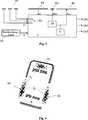
Im oberen Bereich des elektrischen Handgerätes ist hier eine Feldmesselektrode FE der zweiten Elektrodenstruktur eingeordnet. Die Feldmesselektrode FE ist dabei so angeordnet, dass bei einem Umgreifen des Handgerätes durch eine Hand die kapazitive Koppelung zwischen der Sendeelektrode SE und der Feldmesselektrode FE nicht wesentlich beeinflusst bzw. nicht wesentlich verbessert wird. In the upper region of the electrical hand-held device, a field sensing electrode FE of the second electrode structure is arranged here. The Feldmesselektrode FE is arranged so that when a gripping the handset by a hand, the capacitive coupling between the transmitting electrode SE and the field sensing electrode FE is not significantly affected or significantly improved.
Nähert sich nun eine zweite Hand der Feldmesselektrode FE, verbessert sich auch die kapazitive Koppelung zwischen der Sendeelektrode SE und der Feldmesselektrode FE signifikant, was sich wiederum auf den in der Feldmesselektrode FE fließenden Strom auswirkt.If a second hand now approaches the field measuring electrode FE, the capacitive coupling between the transmitting electrode SE and the field measuring electrode FE also improves significantly, which in turn has an effect on the current flowing in the field measuring electrode FE.
Der untere Bereich des Handgerätes wird hier als ”Grip-Zone” bezeichnet, der obere Bereich des Handgerätes wird als ”Prox-Zone” bezeichnet. Ein mögliches Anwendungsszenario der in
Das Umgreifen des Mobiltelefons wird mit Hilfe der Sendeelektrode SE und der Empfangselektrode EE der ersten Elektrodenstruktur detektiert. Die Annäherung an ein Ohr wird durch die Feldmesselektrode FE detektiert. Durch eine Annäherung des Mobiltelefons an das Ohr wird die kapazitive Koppelung zwischen der Sendeelektrode SE und der Feldmesselektrode FE über den Körper des Benutzers stetig größer, bis ab einer gewissen Distanz der Feldmesselektrode FE zum Ohr die kapazitive Koppelung so groß wird, dass der in der Feldmesselektrode FE fließende Strom einen vorbestimmten Pegel überschreitet.The encompassing of the mobile telephone is detected by means of the transmitting electrode SE and the receiving electrode EE of the first electrode structure. The approach to an ear is detected by the field sensing electrode FE. By an approach of the mobile phone to the ear, the capacitive coupling between the transmitting electrode SE and the field measuring electrode FE over the body of the user steadily larger until at a certain distance of the field sensing electrode FE to the ear, the capacitive coupling is so large that in the field sensing electrode FE flowing current exceeds a predetermined level.
Die von der Auswerteeinrichtung A bereitgestellten Detektionssignale können dann beispielsweise derart verwendet werden, dass bei einem eingehenden Anruf das Klingeln eingestellt wird, sobald das Mobiltelefon durch eine Hand umgriffen wird und dass die Displaybeleuchtung des Mobiltelefons automatisch abgeschaltet wird, sobald das Mobiltelefon ans Ohr gehalten wird.The detection signals provided by the evaluation device A can then be used, for example, such that when an incoming call ringing is set, as soon as the mobile phone is surrounded by a hand and the display illumination of the mobile phone is automatically switched off when the mobile phone is held to the ear.
In diesem Beispiel können die Feldmesselektroden FE als Ersatz für herkömmliche mechanische Taster bzw. Schalter verwendet werden. Beispielsweise können die Feldmesselektroden FE bzw. das den Feldmesselektroden FE zugeordnete Detektionssignal mit einer Telefonbuchfunktion eines Mobiltelefons verknüpft sein. Umgreift ein Benutzer nun das Mobiltelefon mit einer Hand und nähert er sich beispielsweise mit dem Daumen der rechten oder der linken Feldmesselektrode FE, kann das Mobiltelefon automatisch in einen Telefonbuchmodus umgeschaltet werden.In this example, the field sensing electrodes FE can be used as a replacement for conventional mechanical switches. For example, the field measuring electrodes FE or the detection signal associated with the field measuring electrodes FE can be linked to a telephone book function of a mobile telephone. If a user now grips the mobile telephone with one hand and approaches, for example, with the thumb of the right or the left field measuring electrode FE, the mobile telephone can automatically be switched to a telephone book mode.
In Kombination mit dem Anwendungsbeispiel, wie es mit Bezug auf
Bei der in
Die hier gezeigte und beschriebene Sensoreinrichtung kann auch dazu verwendet werden, um ein Handgerät, etwa ein Mobiltelefon, von einem ersten Betriebsmodus in einen zweiten Betriebsmodus umzuschalten. Der erste Betriebsmodus kann beispielsweise ein Schlafmodus sein, der zweite Betriebsmodus kann ein Aktivmodus sein. Dadurch kann der Energieverbrauch eines Mobiltelefons deutlich reduziert werden, indem das Mobiltelefon sich nur dann in einem Aktivmodus befindet, wenn es auch tatsächlich von einer Hand umgriffen wird bzw. in Benutzung befindet.The sensor device shown and described herein can also be used to switch a handset, such as a mobile phone, from a first mode of operation to a second mode of operation. The first operating mode may, for example, be a sleep mode, the second operating mode may be an active mode. As a result, the power consumption of a mobile phone can be significantly reduced by the mobile phone is in an active mode only if it is actually embraced by a hand or in use.
In einem anderen Anwendungsszenario kann die erfindungsgemäße Sensoreinrichtung beispielsweise auch in einer Computermaus angeordnet werden. Die Elektroden der ersten Elektrodenstruktur können dabei an der Computermaus so angeordnet werden, dass ein Umgreifen der Computermaus detektiert wird. Die Feldmesselektroden der zweiten Elektrodenstruktur können beispielsweise dafür vorgesehen sein, Annäherungsbereiche für eine linke Maustaste und für eine rechte Maustaste zu definieren. Wird die Computermaus nicht durch eine Hand umfasst, kann die Computermaus in einen Schlafmodus versetzt werden. Aufgrund der erforderlichen kapazitiven Koppelung zwischen der Sendeelektrode und den Feldmesselektroden kann auch vermieden werden, dass eine Computermaus nur durch Annäherung an eine der beiden Feldmesselektroden in einen Aktivmodus versetzt wird, ohne dabei gleichzeitig auch durch die Hand umfasst zu werden. In another application scenario, the sensor device according to the invention can also be arranged, for example, in a computer mouse. The electrodes of the first electrode structure can be arranged on the computer mouse so that a gripping around the computer mouse is detected. For example, the field sensing electrodes of the second electrode structure may be configured to define proximity ranges for a left mouse button and for a right mouse button. If the computer mouse is not covered by one hand, the computer mouse can be put into sleep mode. Due to the required capacitive coupling between the transmitting electrode and the field measuring electrodes, it can also be avoided that a computer mouse is put into an active mode only by approaching one of the two field measuring electrodes without being encompassed by the hand at the same time.
In einem weiteren Anwendungsszenario kann eine Videokamera (Camcorder) mit der erfindungsgemäßen Sensoreinrichtung ausgestattet werden. So kann beispielsweise im Bereich der Kameraschlaufe, in welche die Hand zum Halten der Kamera eingeführt wird, die erste Elektrodenstruktur angeordnet werden. Damit kann detektiert werden, dass sich die Hand in der Schlaufe befindet. In einer Ausgestaltung der Erfindung kann eine Startsequenz der Kamera bzw. des Camcorders eingeleitet werden, sobald sich die Hand in der Schlaufe befindet. Damit kann die Zeitspanne bis zum Start einer Videoaufnahme erheblich verkürzt werden. Das Kamerasystem kann des Weiteren so ausgestaltet sein, dass beim Herausnehmen der Hand aus der Schlaufe, beispielsweise dann, wenn der Camcorder abgestellt wird, zumindest das Display des Camcorders ausgeschaltet wird.In a further application scenario, a video camera (camcorder) can be equipped with the sensor device according to the invention. For example, in the area of the camera cradle into which the hand is inserted for holding the camera, the first electrode structure can be arranged. This can be detected that the hand is in the loop. In one embodiment of the invention, a start sequence of the camera or the camcorder can be initiated as soon as the hand is in the loop. This can significantly reduce the time it takes to start a video recording. The camera system can further be designed so that when removing the hand from the loop, for example, when the camcorder is turned off, at least the display of the camcorder is turned off.
In einer weiteren Ausgestaltung können ein oder mehrere Feldmesselektroden FE an der Videokamera angeordnet werden, mit welchen unterschiedliche Aktionen an der Videokamera ausgelöst werden können, wenn sich ein Finger an eine entsprechende Feldmesselektrode nahe genug annähert. Vorzugsweise sind solche Aktionen mittels der Feldmesselektroden an der Videokamera auslösbar, welche nur dann ausgelöst werden sollen, wenn sich die Hand an der Schlaufe der Videokamera befindet.In a further embodiment, one or more field sensing electrodes FE can be arranged on the video camera with which different actions on the video camera can be triggered when a finger approaches close enough to a corresponding field sensing electrode. Preferably, such actions are triggered by the field measuring electrodes on the video camera, which should only be triggered when the hand is on the loop of the video camera.
Nähert sich nun ein Finger dem Gehäuse in dem Bereich, in welchem eine Feldmesselektrode FE angeordnet ist, nimmt der Pegel des an der Feldmesselektrode FE abgegriffenen elektrischen Signals stetig zu, wie es in der linken Seite der
Um eine an der Innenseite des Gehäuses G angeordnete Feldmesselektrode FE noch besser in eine kapazitive Koppelung zu einem sich annähernden Finger zu bringen, kann an der Gehäuseaußenseite bzw. direkt unterhalb der Oberfläche der Gehäuseaußenseite eine Hilfselektrode HE angeordnet werden. Eine derartige Anordnung ist in
Die Hilfselektrode HE wird dabei in Bezug zu der an der Gehäuseinnenseite angeordneten Feldmesselektrode FE gebracht. Dies kann mittels einer galvanischen Verbindung zwischen der Hilfselektrode HE und der Feldmesselektrode FE bewerkstelligt werden. Die galvanische Verbindung hat den Vorteil, dass die Hilfselektrode HE nicht direkt gegenüber der Feldmesselektrode FE angeordnet werden muss. In einer anderen Ausgestaltung kann die Koppelung der Hilfselektrode HE mit der Feldmesselektrode FE auch auf kapazitiver Basis erfolgen, wie in
Im Vergleich zu den in
Die Unterscheidung zwischen einer Annäherung und einer Berührung kann dafür vorgesehen werden, um beispielsweise bei einer Annäherung an eine Feldmesselektrode eine Fokussierung der Kamera (vgl.
In
Damit lässt sich besonders vorteilhaft ein Umgreifen eines Handgerätes detektieren, während die Detektion lediglich einer Annäherung an das Handgerät effizient vermieden wird.This can be particularly advantageous detect a grasping a handset, while the detection of only an approach to the handset is efficiently avoided.
In einer weiteren hier nicht gezeigten Ausgestaltung der erfindungsgemäßen Sensoreinrichtung kann die erste Elektrodenstruktur auch mehrere Sendeelektroden, mehrere Kompensationselektroden und/oder mehrere Empfangselektroden aufweisen. Ebenso kann die Sensoreinrichtung auch mehrere erste Elektrodenstrukturen umfassen, so dass beispielsweise an einem Handgerät, wenn mehrere erste Elektrodenstrukturen an einem Handgerät angeordnet sind, das Umfassen des Handgerätes an unterschiedlichen Bereichen des Handgerätes detektiert werden kann. Alternativ kann auch detektiert werden, ob das Handgerät von zwei Händen umfasst wird bzw. umgriffen wird.In a further embodiment, not shown here, of the sensor device according to the invention, the first electrode structure can also have a plurality of transmitting electrodes, a plurality of compensation electrodes and / or a plurality of receiving electrodes. Likewise, the sensor device can also comprise a plurality of first electrode structures, so that, for example, on a hand-held device, if a plurality of first electrode structures are arranged on a hand-held device, embracing the hand-held device can be detected at different regions of the hand-held device. Alternatively, it can also be detected whether the handset is encompassed by two hands.
Das Handgerät kann beispielsweise ein Mobiltelefon, eine Computermaus, eine Fernbedienung, ein Eingabemittel für eine Spielkonsole, ein mobiler Kleincomputer (PDA), ein Kopfhörer, oder dergleichen sein. Die erfindungsgemäße Sensoreinrichtung kann auch für größere elektrische Geräte vorgesehen sein, bei welchen es beispielsweise notwendig ist, eine Berührung des Gerätes und gleichzeitig eine Annäherung an das Gerät zu detektieren. Die erfindungsgemäße Sensoreinrichtung kann auch so betrieben werden, dass die an der ersten Elektrodenstruktur abgegriffenen elektrischen Signale unabhängig von den an der zweiten Elektrodenstruktur abgegriffenen elektrischen Signalen ausgewertet werden.The handset may be, for example, a mobile phone, a computer mouse, a remote control, a game console input device, a mobile small computer (PDA), a headset, or the like. The sensor device according to the invention can also be provided for larger electrical devices, in which it is necessary, for example, to detect a touch of the device and at the same time an approach to the device. The sensor device according to the invention can also be operated in such a way that the electrical signals picked up at the first electrode structure are evaluated independently of the electrical signals picked up at the second electrode structure.
Claims (10)
Translated fromGermanPriority Applications (7)
| Application Number | Priority Date | Filing Date | Title |
|---|---|---|---|
| DE102009057947ADE102009057947A1 (en) | 2009-12-11 | 2009-12-11 | Multifunctional touch and / or proximity sensor |
| JP2012542477AJP5833017B2 (en) | 2009-12-11 | 2010-12-03 | Multi-functional contact and / or proximity sensor |
| CN201080055949.1ACN102934359B (en) | 2009-12-11 | 2010-12-03 | Multifunctional touching and/or proximity sense |
| PCT/EP2010/068884WO2011069925A2 (en) | 2009-12-11 | 2010-12-03 | Multifunctional touch and/or proximity sensor |
| US13/512,935US9525416B2 (en) | 2009-12-11 | 2010-12-03 | Multifunctional touch and/or proximity sensor |
| EP10790636AEP2510619A2 (en) | 2009-12-11 | 2010-12-03 | Multifunctional touch and/or proximity sensor |
| KR1020127017671AKR101718847B1 (en) | 2009-12-11 | 2010-12-03 | Multifunctional touch and/or proximity sensor |
Applications Claiming Priority (1)
| Application Number | Priority Date | Filing Date | Title |
|---|---|---|---|
| DE102009057947ADE102009057947A1 (en) | 2009-12-11 | 2009-12-11 | Multifunctional touch and / or proximity sensor |
Publications (1)
| Publication Number | Publication Date |
|---|---|
| DE102009057947A1true DE102009057947A1 (en) | 2011-06-16 |
Family
ID=43978860
Family Applications (1)
| Application Number | Title | Priority Date | Filing Date |
|---|---|---|---|
| DE102009057947AWithdrawnDE102009057947A1 (en) | 2009-12-11 | 2009-12-11 | Multifunctional touch and / or proximity sensor |
Country Status (6)
| Country | Link |
|---|---|
| US (1) | US9525416B2 (en) |
| EP (1) | EP2510619A2 (en) |
| JP (1) | JP5833017B2 (en) |
| KR (1) | KR101718847B1 (en) |
| DE (1) | DE102009057947A1 (en) |
| WO (1) | WO2011069925A2 (en) |
Cited By (5)
| Publication number | Priority date | Publication date | Assignee | Title |
|---|---|---|---|---|
| DE102010044820A1 (en)* | 2010-09-09 | 2012-03-15 | Ident Technology Ag | Sensor device and method for approach and touch detection |
| DE102011075622A1 (en)* | 2011-05-10 | 2012-11-15 | Ident Technology Ag | Sensor and method for detecting a number of objects |
| EP2607932A1 (en)* | 2011-12-19 | 2013-06-26 | Rechner Industrie-Elektronik GmbH | Capacitative measuring method with controllable directional effect and corresponding capacitative sensor for industrial use |
| DE102012006546A1 (en)* | 2012-04-02 | 2013-10-02 | Trw Automotive Electronics & Components Gmbh | Capacitive sensor, method for reading out a capacitive sensor field and method for producing a capacitive sensor field |
| DE202014103874U1 (en)* | 2014-08-21 | 2015-11-25 | Grass Gmbh | Furniture with sensor device |
Families Citing this family (16)
| Publication number | Priority date | Publication date | Assignee | Title |
|---|---|---|---|---|
| US9236860B2 (en)* | 2009-04-07 | 2016-01-12 | Microchip Technology Germany Gmbh | Sensor device and method for grip and proximity detection |
| CN103019554A (en)* | 2011-09-20 | 2013-04-03 | 联想(北京)有限公司 | Command recognition method and electronic device using same |
| US9134397B2 (en)* | 2012-04-17 | 2015-09-15 | Synaptics Incorporated | Reducing bending effects in touch sensor devices |
| US9195354B2 (en)* | 2013-03-12 | 2015-11-24 | Synaptics Incorporated | Device and method for localized force and proximity sensing |
| GB2518871A (en)* | 2013-10-03 | 2015-04-08 | Nokia Technologies Oy | Sensing |
| WO2015065461A1 (en)* | 2013-10-31 | 2015-05-07 | Rinand Solutions Llc | Mechanical structure with integrated electronic components |
| CN106662942A (en)* | 2014-06-27 | 2017-05-10 | 夏普株式会社 | Display unit with touch panel |
| US9632638B2 (en) | 2014-09-10 | 2017-04-25 | Synaptics Incorporated | Device and method for force and proximity sensing employing an intermediate shield electrode layer |
| US10185427B2 (en) | 2014-09-11 | 2019-01-22 | Synaptics Incorporated | Device and method for localized force sensing |
| US9715283B2 (en)* | 2015-02-26 | 2017-07-25 | Motorola Mobility Llc | Method and apparatus for gesture detection in an electronic device |
| KR102278141B1 (en) | 2015-04-09 | 2021-07-19 | 삼성전자주식회사 | Method and apparatus for operating a sensor of electronic device |
| USD776664S1 (en)* | 2015-05-20 | 2017-01-17 | Chaya Coleena Hendrick | Smart card |
| US9671915B2 (en) | 2015-06-30 | 2017-06-06 | Synaptics Incorporated | Avoidance of bending effects in a touch sensor device |
| US10592057B1 (en)* | 2018-11-13 | 2020-03-17 | Synaptics Incorporated | Two layer forcepad |
| DE102019209430A1 (en)* | 2019-06-28 | 2020-12-31 | Robert Bosch Gmbh | Sensor device with capacitive sensor |
| KR102401564B1 (en)* | 2020-03-20 | 2022-05-24 | 주식회사 제이엠엘이디 | Visual acuity test system using artificial intelligence |
Family Cites Families (15)
| Publication number | Priority date | Publication date | Assignee | Title |
|---|---|---|---|---|
| DE2239359A1 (en) | 1972-08-10 | 1974-02-21 | Bosch Gmbh Robert | SWITCH ARRANGEMENT WITH A CAPACITIVE DETECTOR |
| US5594222A (en) | 1994-10-25 | 1997-01-14 | Integrated Controls | Touch sensor and control circuit therefor |
| US6292674B1 (en)* | 1998-08-05 | 2001-09-18 | Ericsson, Inc. | One-handed control for wireless telephone |
| SE9902339L (en)* | 1999-06-21 | 2001-02-20 | Ericsson Telefon Ab L M | Device comprising a capacitive proximity sensing sensor |
| US6859196B2 (en)* | 2001-01-12 | 2005-02-22 | Logitech Europe S.A. | Pointing device with hand detection |
| JP2003029899A (en) | 2001-07-17 | 2003-01-31 | Sony Corp | User input device |
| JP3852368B2 (en) | 2002-05-16 | 2006-11-29 | ソニー株式会社 | Input method and data processing apparatus |
| GB0226404D0 (en) | 2002-11-12 | 2002-12-18 | Koninkl Philips Electronics Nv | Object sensing |
| JP2005317041A (en)* | 2003-02-14 | 2005-11-10 | Sony Corp | Information processor, information processing method, and program |
| GB0310409D0 (en) | 2003-05-07 | 2003-06-11 | Koninkl Philips Electronics Nv | Object sensing |
| US7878075B2 (en) | 2007-05-18 | 2011-02-01 | University Of Southern California | Biomimetic tactile sensor for control of grip |
| WO2009130165A2 (en) | 2008-04-25 | 2009-10-29 | Ident Technology Ag | Electrode system for proximity detection and hand-held device with electrode system |
| DE202008013083U1 (en) | 2008-10-01 | 2008-12-24 | Ident Technology Ag | Contact and switching threshold detection in capacitive switches |
| US9236860B2 (en)* | 2009-04-07 | 2016-01-12 | Microchip Technology Germany Gmbh | Sensor device and method for grip and proximity detection |
| CN103140820B (en)* | 2010-11-05 | 2016-11-09 | 微晶片科技德国公司 | For detecting the method for grasping and the sensor device of handheld device |
- 2009
- 2009-12-11DEDE102009057947Apatent/DE102009057947A1/ennot_activeWithdrawn
- 2010
- 2010-12-03KRKR1020127017671Apatent/KR101718847B1/ennot_activeExpired - Fee Related
- 2010-12-03EPEP10790636Apatent/EP2510619A2/ennot_activeWithdrawn
- 2010-12-03USUS13/512,935patent/US9525416B2/ennot_activeExpired - Fee Related
- 2010-12-03WOPCT/EP2010/068884patent/WO2011069925A2/enactiveApplication Filing
- 2010-12-03JPJP2012542477Apatent/JP5833017B2/ennot_activeExpired - Fee Related
Cited By (10)
| Publication number | Priority date | Publication date | Assignee | Title |
|---|---|---|---|---|
| DE102010044820A1 (en)* | 2010-09-09 | 2012-03-15 | Ident Technology Ag | Sensor device and method for approach and touch detection |
| DE102010044820B4 (en)* | 2010-09-09 | 2015-01-22 | Ident Technology Ag | Sensor device and method for approach and touch detection |
| DE102011075622A1 (en)* | 2011-05-10 | 2012-11-15 | Ident Technology Ag | Sensor and method for detecting a number of objects |
| DE102011075622B4 (en) | 2011-05-10 | 2023-03-02 | Microchip Technology Germany Gmbh | Sensor and method for detecting a number of objects |
| EP2607932A1 (en)* | 2011-12-19 | 2013-06-26 | Rechner Industrie-Elektronik GmbH | Capacitative measuring method with controllable directional effect and corresponding capacitative sensor for industrial use |
| DE102012006546A1 (en)* | 2012-04-02 | 2013-10-02 | Trw Automotive Electronics & Components Gmbh | Capacitive sensor, method for reading out a capacitive sensor field and method for producing a capacitive sensor field |
| DE102012006546B4 (en)* | 2012-04-02 | 2018-02-08 | Trw Automotive Electronics & Components Gmbh | Capacitive sensor, method for reading out a capacitive sensor field and method for producing a capacitive sensor field |
| US10018661B2 (en) | 2012-04-02 | 2018-07-10 | Trw Automotive Electronics & Components Gmbh | Capacitive sensor, method for reading out a capacitive sensor field and method for producing a capacitive sensor field |
| US10398227B2 (en) | 2014-07-21 | 2019-09-03 | Grass Gmbh | Piece of furniture with sensor device |
| DE202014103874U1 (en)* | 2014-08-21 | 2015-11-25 | Grass Gmbh | Furniture with sensor device |
Also Published As
| Publication number | Publication date |
|---|---|
| EP2510619A2 (en) | 2012-10-17 |
| US9525416B2 (en) | 2016-12-20 |
| CN102934359A (en) | 2013-02-13 |
| KR20120102753A (en) | 2012-09-18 |
| KR101718847B1 (en) | 2017-03-22 |
| JP2013513981A (en) | 2013-04-22 |
| JP5833017B2 (en) | 2015-12-16 |
| WO2011069925A3 (en) | 2011-08-18 |
| WO2011069925A2 (en) | 2011-06-16 |
| US20130050139A1 (en) | 2013-02-28 |
Similar Documents
| Publication | Publication Date | Title |
|---|---|---|
| DE102009057947A1 (en) | Multifunctional touch and / or proximity sensor | |
| DE102009057933B3 (en) | Sensor device for detecting approach and touch of e.g. hand held device by hand, has electrode structure including transmission, compensation and receiving electrodes, where electrical field is received in receiving electrode | |
| DE102011003734B3 (en) | Electrode configuration for a capacitive sensor device and capacitive sensor device for approach detection | |
| EP3166228B1 (en) | Sensor module, sensor system and method for capacitive and spatially resolved detection of approaching and contact, use of the sensor module | |
| EP3149855B1 (en) | Sensor device for a motor vehicle | |
| DE102011054690B4 (en) | Electrode device for a capacitive sensor device for position detection | |
| DE102011006079A1 (en) | Measuring device and method for approach detection | |
| DE102011075276B4 (en) | Capacitive sensor device and method for operating an input device | |
| DE102010019841A1 (en) | Printed circuit board for display and display module with display and printed circuit board | |
| DE112012001000T5 (en) | Capacitive touch detection architecture | |
| DE102014016422A1 (en) | Device and method for detecting a steering wheel touch | |
| EP2510620A2 (en) | Device and method for detecting a hand-held device being clasped by a hand | |
| DE10340188A1 (en) | Screen with a touch-sensitive user interface for command input | |
| EP2359476A1 (en) | Capacitive sensor system | |
| EP2759060B1 (en) | Operating device, such as a human-machine interface, in particular for a vehicle component | |
| DE102017105954A1 (en) | Touch display panel and touch display device | |
| EP2888569B1 (en) | Sensor system for detecting a movement of an infrared light source | |
| DE102011083336A1 (en) | Electrode configuration for position detection and position detection | |
| EP2700166B1 (en) | Operating device, in particular for a vehicle component | |
| EP3602786B1 (en) | Home appliance comprising a capacitive touch screen shielded from electromagnetic interference, and method for manufacturing same | |
| DE102010012961B4 (en) | Sensor device and method for approach and touch detection | |
| DE102011002446A1 (en) | Sensor device and method for capacitive proximity detection | |
| DE102011006743B4 (en) | Sensor device and method for detecting a gripping of a hand-held device | |
| EP2974023B1 (en) | Capacitive sensor assembly having a shielding electrode | |
| DE102009057960B4 (en) | Sensor device and method for detecting a gripping of a handset with at least one hand |
Legal Events
| Date | Code | Title | Description |
|---|---|---|---|
| R081 | Change of applicant/patentee | Owner name:IDENT TECHNOLOGY AG, DE Free format text:FORMER OWNER: IDENT TECHNOLOGY AG, 82234 WESSLING, DE Effective date:20110927 Owner name:MICROCHIP TECHNOLOGY GERMANY GMBH, DE Free format text:FORMER OWNER: IDENT TECHNOLOGY AG, 82234 WESSLING, DE Effective date:20110927 | |
| R082 | Change of representative | Representative=s name:2S-IP SCHRAMM SCHNEIDER PATENTANWAELTE - RECHT, DE Representative=s name:2S-IP SCHRAMM SCHNEIDER BERTAGNOLL PATENT- UND, DE | |
| R081 | Change of applicant/patentee | Owner name:MICROCHIP TECHNOLOGY GERMANY GMBH, DE Free format text:FORMER OWNER: IDENT TECHNOLOGY AG, 82205 GILCHING, DE | |
| R082 | Change of representative | Representative=s name:2S-IP SCHRAMM SCHNEIDER PATENTANWAELTE - RECHT, DE Representative=s name:2S-IP SCHRAMM SCHNEIDER BERTAGNOLL PATENT- UND, DE | |
| R012 | Request for examination validly filed | ||
| R119 | Application deemed withdrawn, or ip right lapsed, due to non-payment of renewal fee |