DE102009057792B4 - Continuously pumping infusion pump - Google Patents
Continuously pumping infusion pumpDownload PDFInfo
- Publication number
- DE102009057792B4 DE102009057792B4DE102009057792.0ADE102009057792ADE102009057792B4DE 102009057792 B4DE102009057792 B4DE 102009057792B4DE 102009057792 ADE102009057792 ADE 102009057792ADE 102009057792 B4DE102009057792 B4DE 102009057792B4
- Authority
- DE
- Germany
- Prior art keywords
- chamber
- piston
- outlet
- inlet
- infusion pump
- Prior art date
- Legal status (The legal status is an assumption and is not a legal conclusion. Google has not performed a legal analysis and makes no representation as to the accuracy of the status listed.)
- Expired - Fee Related
Links
- 238000001802infusionMethods0.000titleclaimsabstractdescription37
- 238000005086pumpingMethods0.000titledescription2
- 239000012530fluidSubstances0.000claimsabstractdescription17
- 238000004891communicationMethods0.000claimsabstractdescription9
- 238000004519manufacturing processMethods0.000claimsdescription5
- 239000003814drugSubstances0.000description13
- 229940079593drugDrugs0.000description11
- 239000007788liquidSubstances0.000description11
- 238000009530blood pressure measurementMethods0.000description3
- 238000010276constructionMethods0.000description3
- 238000000034methodMethods0.000description3
- 238000013461designMethods0.000description2
- 238000001647drug administrationMethods0.000description2
- 238000012377drug deliveryMethods0.000description2
- 238000005259measurementMethods0.000description2
- 241000287828Gallus gallusSpecies0.000description1
- 238000005452bendingMethods0.000description1
- 210000005013brain tissueAnatomy0.000description1
- 230000001419dependent effectEffects0.000description1
- 238000001514detection methodMethods0.000description1
- 230000005484gravityEffects0.000description1
- 238000002347injectionMethods0.000description1
- 239000007924injectionSubstances0.000description1
- 239000012528membraneSubstances0.000description1
- 230000007935neutral effectEffects0.000description1
- 230000003287optical effectEffects0.000description1
- 230000001225therapeutic effectEffects0.000description1
Images


Classifications
- F—MECHANICAL ENGINEERING; LIGHTING; HEATING; WEAPONS; BLASTING
- F04—POSITIVE - DISPLACEMENT MACHINES FOR LIQUIDS; PUMPS FOR LIQUIDS OR ELASTIC FLUIDS
- F04B—POSITIVE-DISPLACEMENT MACHINES FOR LIQUIDS; PUMPS
- F04B25/00—Multi-stage pumps
- F04B25/005—Multi-stage pumps with two cylinders
- A—HUMAN NECESSITIES
- A61—MEDICAL OR VETERINARY SCIENCE; HYGIENE
- A61M—DEVICES FOR INTRODUCING MEDIA INTO, OR ONTO, THE BODY; DEVICES FOR TRANSDUCING BODY MEDIA OR FOR TAKING MEDIA FROM THE BODY; DEVICES FOR PRODUCING OR ENDING SLEEP OR STUPOR
- A61M5/00—Devices for bringing media into the body in a subcutaneous, intra-vascular or intramuscular way; Accessories therefor, e.g. filling or cleaning devices, arm-rests
- A61M5/14—Infusion devices, e.g. infusing by gravity; Blood infusion; Accessories therefor
- A61M5/142—Pressure infusion, e.g. using pumps
- A61M5/14212—Pumping with an aspiration and an expulsion action
- A61M5/14216—Reciprocating piston type
- A61M5/1422—Reciprocating piston type with double acting or multiple pistons
- A—HUMAN NECESSITIES
- A61—MEDICAL OR VETERINARY SCIENCE; HYGIENE
- A61M—DEVICES FOR INTRODUCING MEDIA INTO, OR ONTO, THE BODY; DEVICES FOR TRANSDUCING BODY MEDIA OR FOR TAKING MEDIA FROM THE BODY; DEVICES FOR PRODUCING OR ENDING SLEEP OR STUPOR
- A61M5/00—Devices for bringing media into the body in a subcutaneous, intra-vascular or intramuscular way; Accessories therefor, e.g. filling or cleaning devices, arm-rests
- A61M5/36—Devices for bringing media into the body in a subcutaneous, intra-vascular or intramuscular way; Accessories therefor, e.g. filling or cleaning devices, arm-rests with means for eliminating or preventing injection or infusion of air into body
- A61M5/365—Air detectors
- F—MECHANICAL ENGINEERING; LIGHTING; HEATING; WEAPONS; BLASTING
- F04—POSITIVE - DISPLACEMENT MACHINES FOR LIQUIDS; PUMPS FOR LIQUIDS OR ELASTIC FLUIDS
- F04B—POSITIVE-DISPLACEMENT MACHINES FOR LIQUIDS; PUMPS
- F04B1/00—Multi-cylinder machines or pumps characterised by number or arrangement of cylinders
- F04B1/02—Multi-cylinder machines or pumps characterised by number or arrangement of cylinders having two cylinders
- F—MECHANICAL ENGINEERING; LIGHTING; HEATING; WEAPONS; BLASTING
- F04—POSITIVE - DISPLACEMENT MACHINES FOR LIQUIDS; PUMPS FOR LIQUIDS OR ELASTIC FLUIDS
- F04B—POSITIVE-DISPLACEMENT MACHINES FOR LIQUIDS; PUMPS
- F04B3/00—Machines or pumps with pistons coacting within one cylinder, e.g. multi-stage
- F—MECHANICAL ENGINEERING; LIGHTING; HEATING; WEAPONS; BLASTING
- F04—POSITIVE - DISPLACEMENT MACHINES FOR LIQUIDS; PUMPS FOR LIQUIDS OR ELASTIC FLUIDS
- F04B—POSITIVE-DISPLACEMENT MACHINES FOR LIQUIDS; PUMPS
- F04B7/00—Piston machines or pumps characterised by having positively-driven valving
- F04B7/0003—Piston machines or pumps characterised by having positively-driven valving the distribution member forming both the inlet and discharge distributor for one single pumping chamber
- F04B7/0007—Piston machines or pumps characterised by having positively-driven valving the distribution member forming both the inlet and discharge distributor for one single pumping chamber and having a rotating movement
Landscapes
- Engineering & Computer Science (AREA)
- Health & Medical Sciences (AREA)
- Mechanical Engineering (AREA)
- General Engineering & Computer Science (AREA)
- Hematology (AREA)
- Anesthesiology (AREA)
- Biomedical Technology (AREA)
- Heart & Thoracic Surgery (AREA)
- Vascular Medicine (AREA)
- Life Sciences & Earth Sciences (AREA)
- Animal Behavior & Ethology (AREA)
- General Health & Medical Sciences (AREA)
- Public Health (AREA)
- Veterinary Medicine (AREA)
- Emergency Medicine (AREA)
- Infusion, Injection, And Reservoir Apparatuses (AREA)
- Reciprocating Pumps (AREA)
Abstract
Translated fromGermanDescription
Translated fromGermanDie Erfindung betrifft eine Infusionspumpe zum kontinuierlichen Fördern eines Fluids, mit einem Einlass, einem Auslass, einen in einer ersten Kammer verschieblich gelagerten ersten Kolben, und einem in einer zweiten Kammer verschieblich gelagerten zweiten Kolben. Insbesondere betrifft die Erfindung eine Infusionspumpe mit der Kleinstmengen eines Medikaments genau und mit einer beständig gleichbleibenden Fluss- bzw. Förderrate appliziert werden können.The invention relates to an infusion pump for continuously conveying a fluid, having an inlet, an outlet, a first piston displaceably mounted in a first chamber, and a second piston displaceably mounted in a second chamber. In particular, the invention relates to an infusion pump with the smallest amounts of a drug can be applied accurately and with a consistently constant flow or delivery rate.
Infusionspumpen sind beispielsweise aus der
Aus der
Nachteil dieser Infusionspumpe ist jedoch, dass aufgrund des Ventilspiels zusätzliches Volumen im Ventil erzeugt wird, wenn das Ventil geöffnet wird, wodurch eine Minderförderung des Medikaments erfolgt. Andererseits wird dieses Mindervolumen beim Schließen des Ventils wieder verdrängt, sodass eine Mehrförderung die Folge ist.Disadvantage of this infusion pump, however, is that due to the valve clearance additional volume is generated in the valve when the valve is opened, whereby a reduced production of the drug takes place. On the other hand, this smaller volume is displaced again when closing the valve, so that a more promotion is the result.
Über einen längeren Zeitraum betrachtet entspricht die Medikamentenabgabe zwar dem vom Arzt vorgesehenen Therapieplan. Allerdings kann unter Umständen bereits eine zeitlich nur kurze Minder- oder Mehrversorgung des Patienten mit dem von der Infusionspumpe geförderten Medikament – abhängig vom Medikament – dazu führen, dass der gewünschte Therapieerfolg nicht erreicht wird.Considered over a longer period of time, the release of medication corresponds to the treatment plan provided by the doctor. However, under certain circumstances, a short-term or short-term supply of the patient with the drug promoted by the infusion pump - depending on the drug - may lead to the desired therapeutic success not being achieved.
Andere im medizinischen Umfeld verwendete Pumpvorrichtungen sind beispielsweise aus der
Aufgabe der Erfindung ist es daher, eine Infusionspumpe zu schaffen, mit der auch sehr kleine Flüssigkeitsmengen, bevorzugt im Mikroliterbereich, sehr genau und kontinuierlich zu fördern.The object of the invention is therefore to provide an infusion pump, with the very small amounts of liquid, preferably in the microliter range to promote very accurate and continuous.
Diese Aufgabe wird durch die Infusionspumpe mit den Merkmalen von Anspruch 1 und die Infusionspumpe mit den Merkmalen von Anspruch 2 gelöst. Die Unteransprüche geben vorteilhafte Ausgestaltungen der Erfindung wieder.This object is achieved by the infusion pump having the features of claim 1 and the infusion pump having the features of claim 2. The subclaims reflect advantageous embodiments of the invention.
Die kontinuierlich fördernde Infusionspumpe nach der Erfindung stellt durch die Anordnung der ersten, als Förderkammer bezeichneten Kammer und der zweiten, als Ausgleichskammer bezeichneten Kammer zusammen mit volumenneutralen Ventilen sicher, dass die Medikamentengabe nur von der Ansteuerung der Aktoren der vorgenannten Elemente abhängig und damit bei identischen Ansteuerungszyklen bei jeder gewünschten Förderrate kontinuierlich ist.The continuously conveying infusion pump according to the invention provides by the arrangement of the first, referred to as a delivery chamber chamber and the second, referred to as compensation chamber chamber together with volume neutral valves sure that the medication only depends on the control of the actuators of the aforementioned elements and thus with identical driving cycles is continuous at any desired delivery rate.
Die Erfindung wird anhand eines besonders bevorzugt ausgestalteten Ausführungsbeispiels näher erläutert. Es zeigen:The invention will be explained in more detail with reference to a particularly preferred embodiment. Show it:
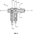
Die Infusionspumpe
Die Kolben
Erfindungsgemäß ist ein als 2-Weg-Hahn ausgebildetes Stellelement
Das Stellelement
In einer zweiten, beispielsweise um 180° gedrehten Position des 2-Wegehahns
Alternativ kann das Stellelement aber auch anstelle des Hahns
Als weitere bevorzugte Ausgestaltung der Alternative ist es denkbar, dass das erste Ventil als Rückschlagventil und das zweite Ventil als durch einen Aktuator betätigtes Ventil ausgebildet ist. Wiederum als besonders bevorzugte Alternative zu dieser Ausgestaltung kann das erste Ventil als Rückschlagventil und das zweite Ventil als Siphon ausgestaltet sein, dass bevorzugt erst bei einem Differenzdruck von > 100 hPa öffnet.As a further preferred embodiment of the alternative, it is conceivable that the first valve is designed as a check valve and the second valve is designed as actuated by an actuator valve. Again, as a particularly preferred alternative to this embodiment, the first valve may be designed as a check valve and the second valve as a siphon that preferably opens only at a differential pressure of> 100 hPa.
Dabei sind die Bewegungen der beiden Kolben
Im Ausführungsbeispiel ist die verbundene Einheit zum Anschluss zur Druckmessung als Kolben
Schließlich ist auch ein Bereich
Zusammenfassend wird noch einmal der Ablauf der Verfahrensablauf der von der Steuerung gesteuerten Infusionspumpe beschrieben:
Das Küken
The
Darauf wird der Förderkolben
Nachdem die Förderkammer
Jetzt wird das Küken
Durch die Eigenschaft der erfindungsgemäßen kontinuierlich fördernde Infusionspumpe
Jederzeit ist es möglich, die Ausfließgeschwindigkeit der Flüssigkeit zwischen der minimalen und maximalen vorgesehenen Grenze durch entsprechende Ansteuerung der Aktoren zu ändern. Diese Grenzen sind von der Ausführung der Pumpe
Schließlich ermöglicht die Erfindung auch eine Ausgestaltung der Infusionspumpe
Die Pumpe erfüllt unter anderem auch die Anforderung zum Einsatz der Arzneimittelgabe direkt in das Hirngewebe nach der „Convection Enhanced Delivery” (CED) Methode, die gegenüber der nicht kontinuierlichen Arzneimittelgabe große Vorteile aufweist.Among other things, the pump fulfills the requirement for the use of drug delivery directly into the brain tissue according to the Convection Enhanced Delivery (CED) method, which has great advantages over non-continuous drug administration.
Claims (6)
Translated fromGermanPriority Applications (5)
| Application Number | Priority Date | Filing Date | Title |
|---|---|---|---|
| DE102009057792.0ADE102009057792B4 (en) | 2009-12-11 | 2009-12-11 | Continuously pumping infusion pump |
| US13/512,720US9267498B2 (en) | 2009-12-11 | 2010-12-10 | Continuously conveying infusion pump |
| PCT/DE2010/001438WO2011069494A2 (en) | 2009-12-11 | 2010-12-10 | Continuously conveying infusion pump |
| EP10805582.3AEP2510234B1 (en) | 2009-12-11 | 2010-12-10 | Continuously conveying infusion pump |
| ES10805582TES2718298T3 (en) | 2009-12-11 | 2010-12-10 | Continuous pumping infusion pump |
Applications Claiming Priority (1)
| Application Number | Priority Date | Filing Date | Title |
|---|---|---|---|
| DE102009057792.0ADE102009057792B4 (en) | 2009-12-11 | 2009-12-11 | Continuously pumping infusion pump |
Publications (2)
| Publication Number | Publication Date |
|---|---|
| DE102009057792A1 DE102009057792A1 (en) | 2011-06-16 |
| DE102009057792B4true DE102009057792B4 (en) | 2016-08-18 |
Family
ID=43754889
Family Applications (1)
| Application Number | Title | Priority Date | Filing Date |
|---|---|---|---|
| DE102009057792.0AExpired - Fee RelatedDE102009057792B4 (en) | 2009-12-11 | 2009-12-11 | Continuously pumping infusion pump |
Country Status (5)
| Country | Link |
|---|---|
| US (1) | US9267498B2 (en) |
| EP (1) | EP2510234B1 (en) |
| DE (1) | DE102009057792B4 (en) |
| ES (1) | ES2718298T3 (en) |
| WO (1) | WO2011069494A2 (en) |
Cited By (6)
| Publication number | Priority date | Publication date | Assignee | Title |
|---|---|---|---|---|
| US11890452B2 (en) | 2012-10-11 | 2024-02-06 | Magnolia Medical Technologies, Inc. | Systems and methods for delivering a fluid to a patient with reduced contamination |
| US11903709B2 (en) | 2017-09-12 | 2024-02-20 | Magnolia Medical Technologies, Inc. | Fluid control devices and methods of using the same |
| US11998332B2 (en) | 2012-05-30 | 2024-06-04 | Magnolia Medical Technologies, Inc. | Fluid diversion mechanism for bodily-fluid sampling |
| US12083234B2 (en) | 2015-09-03 | 2024-09-10 | Magnolia Medical Technologies, Inc. | Apparatus and methods for maintaining sterility of a specimen container |
| US12150763B2 (en) | 2012-12-04 | 2024-11-26 | Magnolia Medical Technologies, Inc. | Sterile bodily-fluid collection device and methods |
| US12186080B2 (en) | 2012-05-30 | 2025-01-07 | Magnolia Medical Technologies, Inc. | Fluid diversion mechanism for bodily-fluid sampling |
Families Citing this family (13)
| Publication number | Priority date | Publication date | Assignee | Title |
|---|---|---|---|---|
| AU2013264969A1 (en)* | 2012-05-23 | 2014-12-11 | Swissinnov Product Sarl | Pulsation-free positive displacement rotary pump |
| CN109171766A (en) | 2012-11-30 | 2019-01-11 | 木兰医药技术股份有限公司 | Body fluid barrier means and the method for completely cutting off body fluid using body fluid barrier means |
| CA3183294A1 (en) | 2012-12-04 | 2014-06-12 | Magnolia Medical Technologies, Inc. | Sterile bodily-fluid collection device and methods |
| WO2015132645A1 (en)* | 2014-03-02 | 2015-09-11 | Swissinnov Product Sarl | Volumetric pump with bleed mechanism |
| ES2716964T3 (en)* | 2014-10-13 | 2019-06-18 | Alfa Srl | Volumetric pump and pumping group for fluid products and their method of use |
| EP3261694B1 (en) | 2015-02-24 | 2021-03-24 | 410 Medical, Inc. | Apparatus and kits for fluid infusion |
| WO2016201406A1 (en) | 2015-06-12 | 2016-12-15 | Bullington Gregory J | Devices and methods for syringe-based fluid transfer for bodily-fluid sampling |
| JP7229267B2 (en) | 2017-12-07 | 2023-02-27 | マグノリア メディカル テクノロジーズ,インコーポレイテッド | Fluid control device and method of use |
| WO2020163744A1 (en) | 2019-02-08 | 2020-08-13 | Magnolia Medical Technologies, Inc. | Devices and methods for bodily fluid collection and distribution |
| CN113784793B (en) | 2019-03-11 | 2023-09-19 | 木兰医药技术股份有限公司 | Fluid control device and method of using the same |
| CN111053958A (en)* | 2019-12-27 | 2020-04-24 | 南微医学科技股份有限公司 | Receptacles, pump heads and pressure pumps |
| US11229750B2 (en) | 2020-04-06 | 2022-01-25 | Veloject, Llc | Injection device |
| US12138433B2 (en) | 2021-10-05 | 2024-11-12 | Veloject, Llc | Aspiration and injection devices |
Citations (4)
| Publication number | Priority date | Publication date | Assignee | Title |
|---|---|---|---|---|
| DE3032475A1 (en)* | 1980-08-28 | 1982-02-25 | Hans Dr.med. Dr.med.dent. 8000 München Scheicher | Sterilised liquid continuous preparation method - mixes liquid and disinfectant in first vessel before transfer to second |
| US4808077A (en)* | 1987-01-09 | 1989-02-28 | Hitachi, Ltd. | Pulsationless duplex plunger pump and control method thereof |
| US20070261553A1 (en)* | 2006-05-09 | 2007-11-15 | Yuri Gerner | Capillary flow restrictor apparatus |
| WO2008141337A1 (en)* | 2007-05-16 | 2008-11-20 | Smiths Medical Asd, Inc. | Pump module for use in a medical fluid dispensing system |
Family Cites Families (7)
| Publication number | Priority date | Publication date | Assignee | Title |
|---|---|---|---|---|
| US4627419A (en)* | 1984-08-29 | 1986-12-09 | The Board Of Regents, The University Of Texas | Blood pump apparatus and method |
| DE4016306A1 (en) | 1990-05-21 | 1991-11-28 | Kitronic Mikrotech | RADIAL PISTON PUMP |
| US6203528B1 (en)* | 1995-03-06 | 2001-03-20 | Baxter International Inc. | Unitary molded elastomer conduit for use with a medical infusion pump |
| US6183211B1 (en)* | 1999-02-09 | 2001-02-06 | Devilbiss Air Power Company | Two stage oil free air compressor |
| ES2284943T3 (en)* | 2001-11-16 | 2007-11-16 | Medinnovation Ag | MEDICINAL PUMPING DEVICE. |
| US7270647B2 (en)* | 2004-03-04 | 2007-09-18 | Boehringer Technologies, L.P. | Apparatus for vacuum-assisted irrigation and drainage of a body cavity |
| US20070083160A1 (en)* | 2005-10-06 | 2007-04-12 | Hall W D | System and method for assessing measurements made by a body fluid analyzing device |
- 2009
- 2009-12-11DEDE102009057792.0Apatent/DE102009057792B4/ennot_activeExpired - Fee Related
- 2010
- 2010-12-10EPEP10805582.3Apatent/EP2510234B1/enactiveActive
- 2010-12-10USUS13/512,720patent/US9267498B2/enactiveActive
- 2010-12-10ESES10805582Tpatent/ES2718298T3/enactiveActive
- 2010-12-10WOPCT/DE2010/001438patent/WO2011069494A2/enactiveApplication Filing
Patent Citations (4)
| Publication number | Priority date | Publication date | Assignee | Title |
|---|---|---|---|---|
| DE3032475A1 (en)* | 1980-08-28 | 1982-02-25 | Hans Dr.med. Dr.med.dent. 8000 München Scheicher | Sterilised liquid continuous preparation method - mixes liquid and disinfectant in first vessel before transfer to second |
| US4808077A (en)* | 1987-01-09 | 1989-02-28 | Hitachi, Ltd. | Pulsationless duplex plunger pump and control method thereof |
| US20070261553A1 (en)* | 2006-05-09 | 2007-11-15 | Yuri Gerner | Capillary flow restrictor apparatus |
| WO2008141337A1 (en)* | 2007-05-16 | 2008-11-20 | Smiths Medical Asd, Inc. | Pump module for use in a medical fluid dispensing system |
Cited By (10)
| Publication number | Priority date | Publication date | Assignee | Title |
|---|---|---|---|---|
| US11998332B2 (en) | 2012-05-30 | 2024-06-04 | Magnolia Medical Technologies, Inc. | Fluid diversion mechanism for bodily-fluid sampling |
| US12186080B2 (en) | 2012-05-30 | 2025-01-07 | Magnolia Medical Technologies, Inc. | Fluid diversion mechanism for bodily-fluid sampling |
| US12193816B2 (en) | 2012-05-30 | 2025-01-14 | Magnolia Medical Technologies, Inc. | Fluid diversion mechanism for bodily-fluid sampling |
| US11890452B2 (en) | 2012-10-11 | 2024-02-06 | Magnolia Medical Technologies, Inc. | Systems and methods for delivering a fluid to a patient with reduced contamination |
| US12133968B2 (en) | 2012-10-11 | 2024-11-05 | Magnolia Medical Technologies, Inc. | Systems and methods for delivering a fluid to a patient with reduced contamination |
| US12150763B2 (en) | 2012-12-04 | 2024-11-26 | Magnolia Medical Technologies, Inc. | Sterile bodily-fluid collection device and methods |
| US12083234B2 (en) | 2015-09-03 | 2024-09-10 | Magnolia Medical Technologies, Inc. | Apparatus and methods for maintaining sterility of a specimen container |
| US11903709B2 (en) | 2017-09-12 | 2024-02-20 | Magnolia Medical Technologies, Inc. | Fluid control devices and methods of using the same |
| US11903710B2 (en) | 2017-09-12 | 2024-02-20 | Magnolia Medical Technologies, Inc. | Fluid control devices and methods of using the same |
| US12290363B2 (en) | 2017-09-12 | 2025-05-06 | Magnolia Medical Technologies, Inc. | Fluid control devices and methods of using the same |
Also Published As
| Publication number | Publication date |
|---|---|
| WO2011069494A3 (en) | 2011-09-15 |
| EP2510234B1 (en) | 2019-03-06 |
| US20120265128A1 (en) | 2012-10-18 |
| DE102009057792A1 (en) | 2011-06-16 |
| US9267498B2 (en) | 2016-02-23 |
| ES2718298T3 (en) | 2019-07-01 |
| EP2510234A2 (en) | 2012-10-17 |
| WO2011069494A2 (en) | 2011-06-16 |
Similar Documents
| Publication | Publication Date | Title |
|---|---|---|
| DE102009057792B4 (en) | Continuously pumping infusion pump | |
| DE102012209314B4 (en) | Device and method for dispensing or receiving a liquid volume | |
| EP3012600B1 (en) | Dosing device for an infusion system | |
| DE3685508T2 (en) | INFUSION PUMP WITH AVAILABLE CASSETTE. | |
| DE69328271T2 (en) | Liquid control device with automatic valve | |
| EP2788046B1 (en) | Pump for medical purposes | |
| EP1944084B1 (en) | Valve device for a micro fluid system | |
| DE102010030504A1 (en) | Quellstoffaktor with electrically driven fluidic transport device | |
| EP2535071B1 (en) | Medication device for metered discharge of a liquid media | |
| EP1745812B1 (en) | Valve for a fluid, in particular for being used in a mechanically actuated liquid pump | |
| EP4204038A1 (en) | Infusion or transfusion set and system comprising an infusion or transfusion set | |
| EP1941947A1 (en) | valve assenbly for a microfluidic system | |
| DE102015224622A1 (en) | FREISTRAHLDOSIERSYSTEM | |
| EP3096818B1 (en) | Method and apparatus for flow control through a medical infusion line | |
| DE4219664C2 (en) | Delivery unit for a positive displacement metering pump | |
| EP2446910A1 (en) | Pump and method for conveying a fluid and cavity for a pump | |
| EP3140242B1 (en) | Filling device | |
| WO2008098947A1 (en) | Apparatus and method for dosing liquids into gas-filled chambers | |
| CH705428A2 (en) | Infusion adapter for fluid product administering apparatus used for administering e.g. liquid form medicament, has diaphragm valve arranged at the center of valve seat or in periphery of valve membrane, to simplify assembly of adapter | |
| EP2964294B1 (en) | Device for regulating a volumetric flow rate | |
| DE102010038225B4 (en) | Tubular diaphragm process pump | |
| EP3890804A1 (en) | Infusion arrangement for administering a medical fluid | |
| EP3628345B1 (en) | Kit for modular assembly of a medical pumping device and medical pumping device | |
| WO2022002947A1 (en) | Method and device for metering solutions | |
| EP4279116A1 (en) | Implantable pump device for pumping a body fluid |
Legal Events
| Date | Code | Title | Description |
|---|---|---|---|
| OP8 | Request for examination as to paragraph 44 patent law | ||
| R016 | Response to examination communication | ||
| R016 | Response to examination communication | ||
| R016 | Response to examination communication | ||
| R018 | Grant decision by examination section/examining division | ||
| R020 | Patent grant now final | ||
| R081 | Change of applicant/patentee | Owner name:LENUS INFUSIONSTECHNIK GMBH & CO. KG, DE Free format text:FORMER OWNER: KOELLN, HARM, 24159 KIEL, DE | |
| R082 | Change of representative | Representative=s name:BOEHMERT & BOEHMERT ANWALTSPARTNERSCHAFT MBB -, DE Representative=s name:LOBEMEIER, MARTIN LANDOLF, DR., DE | |
| R082 | Change of representative | Representative=s name:LOBEMEIER, MARTIN LANDOLF, DR., DE | |
| R119 | Application deemed withdrawn, or ip right lapsed, due to non-payment of renewal fee |